


700 Series
Managed Industrial
Ethernet Switch
User Manual &
Installation
Guide
|
|
(Revised 2013-06-21) |
Page 1 of 154 |
708TX, 708FX2, 708FXE2, 716TX, 716FX2, and 716FXE2 Industrial Ethernet Switch Installation Guide............. |
4 |
|
Installation.................................................................................................................................................................... |
|
7 |
Connecting the Unit ................................................................................................................................................... |
|
14 |
Overview of Advanced Features................................................................................................................................ |
|
18 |
Mode of Operation .................................................................................................................................................................. |
|
18 |
Port Mirroring ......................................................................................................................................................................... |
|
18 |
Port Trunking .......................................................................................................................................................................... |
|
18 |
Quality of Service (QoS)......................................................................................................................................................... |
|
18 |
Virtual LAN ............................................................................................................................................................................ |
|
19 |
Rapid Spanning Tree Protocol ................................................................................................................................................ |
|
20 |
SNMP Traps............................................................................................................................................................................ |
|
20 |
IGMP Snooping ...................................................................................................................................................................... |
|
20 |
N-Ring..................................................................................................................................................................................... |
|
20 |
N-Link..................................................................................................................................................................................... |
|
21 |
CIP .......................................................................................................................................................................................... |
|
21 |
DHCP...................................................................................................................................................................................... |
|
21 |
DHCP Client ........................................................................................................................................................................... |
|
21 |
DHCP Relay Agent ................................................................................................................................................................. |
|
22 |
DHCP Server........................................................................................................................................................................... |
|
22 |
LLDP....................................................................................................................................................................................... |
|
22 |
Port Security—MAC Address Based ...................................................................................................................................... |
|
22 |
Web Software Configuration ..................................................................................................................................... |
|
24 |
Web Management ................................................................................................................................................................... |
|
24 |
Web Management - Home ...................................................................................................................................................... |
|
25 |
Administration – System......................................................................................................................................................... |
|
27 |
Administration – SNMP.......................................................................................................................................................... |
|
30 |
Administration – Fault ............................................................................................................................................................ |
|
32 |
DHCP – Server – Setup Profiles ............................................................................................................................................. |
|
34 |
DHCP – Server – Setup IP Maps ............................................................................................................................................ |
|
36 |
DHCP – Server – View Bindings............................................................................................................................................ |
|
41 |
DHCP – Relay & Local IP - Setup.......................................................................................................................................... |
|
42 |
LLDP - Configuration ............................................................................................................................................................. |
|
44 |
LLDP - Ports ........................................................................................................................................................................... |
|
45 |
LLDP - Status.......................................................................................................................................................................... |
|
46 |
LLDP - Statistics ..................................................................................................................................................................... |
|
47 |
Ports – Configuration .............................................................................................................................................................. |
|
48 |
Ports – MAC Security – Learning........................................................................................................................................... |
|
51 |
Ports – MAC Security – Authorization List ............................................................................................................................ |
|
52 |
Ports – MAC Security – Intruder Log ..................................................................................................................................... |
|
53 |
Ports – Mirroring..................................................................................................................................................................... |
|
54 |
Ports – Trunking...................................................................................................................................................................... |
|
56 |
Ports – QOS ............................................................................................................................................................................ |
|
57 |
Statistics – Port Statistics ........................................................................................................................................................ |
|
59 |
Statistics – Port Utilization...................................................................................................................................................... |
|
60 |
VLAN – Configuration ........................................................................................................................................................... |
|
61 |
Bridging – Aging Time ........................................................................................................................................................... |
|
64 |
Bridging – Unicast Addresses ................................................................................................................................................. |
|
65 |
Bridging – Multicast Addresses .............................................................................................................................................. |
|
67 |
Bridging – Show MAC by Port............................................................................................................................................... |
|
69 |
RSTP – Configuration............................................................................................................................................................. |
|
71 |
IGMP – Configuration ............................................................................................................................................................ |
|
74 |
IGMP – Show Group and Show Router.................................................................................................................................. |
|
77 |
IGMP – RFilter ....................................................................................................................................................................... |
|
78 |
N-View – Configuration.......................................................................................................................................................... |
|
80 |
N-View – Ports........................................................................................................................................................................ |
|
81 |
N-Ring – Configuration .......................................................................................................................................................... |
|
82 |
N-Ring – Advanced Configuration ......................................................................................................................................... |
|
85 |
N-Ring – Status ....................................................................................................................................................................... |
|
87 |
N-Link – Configuration........................................................................................................................................................... |
|
91 |
(Revised 2013-06-21) |
Page 2 of 154 |
|
N-Link – Status ....................................................................................................................................................................... |
95 |
CIP – Configuration .............................................................................................................................................................. |
100 |
CIP – Status........................................................................................................................................................................... |
101 |
Firmware/Config – TFTP...................................................................................................................................................... |
102 |
Support – Web Site and E-mail............................................................................................................................................. |
103 |
BPCL – Broadcast Packet Count Limit Configuration ......................................................................................................... |
104 |
User Management – Adding Users ....................................................................................................................................... |
105 |
User Management – Removing Users................................................................................................................................... |
106 |
LogicalView.......................................................................................................................................................................... |
107 |
Configuration – Save or Reset............................................................................................................................................... |
108 |
Help – Overview ................................................................................................................................................................... |
109 |
Help – Administration........................................................................................................................................................... |
110 |
Help – DHCP ........................................................................................................................................................................ |
111 |
Help – LLDP......................................................................................................................................................................... |
112 |
Help – Ports........................................................................................................................................................................... |
113 |
Help – Statistics..................................................................................................................................................................... |
114 |
Help – VLAN........................................................................................................................................................................ |
115 |
Help – Bridging..................................................................................................................................................................... |
116 |
Help – RSTP ......................................................................................................................................................................... |
117 |
Help – IGMP......................................................................................................................................................................... |
118 |
Help – N-View ...................................................................................................................................................................... |
119 |
Help – N-Ring ....................................................................................................................................................................... |
120 |
Help – N-Link ....................................................................................................................................................................... |
121 |
Help – CIP............................................................................................................................................................................. |
122 |
Help – BPCL......................................................................................................................................................................... |
124 |
Help – User Management...................................................................................................................................................... |
125 |
CLI Commands ........................................................................................................................................................ |
127 |
“?” (Help).............................................................................................................................................................................. |
127 |
Logout ................................................................................................................................................................................... |
127 |
Show, Add, or Delete ARL Entries....................................................................................................................................... |
128 |
Show or Set CIP Configuration............................................................................................................................................. |
129 |
Save or Reset the Configuration Settings.............................................................................................................................. |
130 |
Show or Set IGMP Configuration ......................................................................................................................................... |
130 |
Show or Set Mirror Configuration ........................................................................................................................................ |
131 |
Show or Set N-Ring Configuration ....................................................................................................................................... |
132 |
Show or Set N-View Configuration ...................................................................................................................................... |
132 |
Ping a Host ............................................................................................................................................................................ |
133 |
Show or Set Port Configuration ............................................................................................................................................ |
134 |
Reset the Switch.................................................................................................................................................................... |
135 |
Show or Set SNMP Configuration ........................................................................................................................................ |
135 |
Show or Clear the Last System Error.................................................................................................................................... |
136 |
Show System Information..................................................................................................................................................... |
136 |
Set or Show the System IP Configuration............................................................................................................................. |
137 |
Show or Set System Configuration ....................................................................................................................................... |
138 |
VLAN Addition and Deletion Example................................................................................................................... |
139 |
VLAN Configuration Examples .............................................................................................................................. |
145 |
Example 1 – Basic understanding of port-based VLANs...................................................................................................... |
145 |
Example 2 – Basic understanding of tagged VLANs (Admit – Tagged Only) ..................................................................... |
146 |
Example 3 – Basic understanding of tagged VLANs (Admit – All) ..................................................................................... |
147 |
Example 4 – Basic understanding of Hybrid VLANs ........................................................................................................... |
148 |
Example 5 – Basic understanding of Overlapping VLANs................................................................................................... |
149 |
Example 6 – Basic understanding of VLANs with Multicast Filtering................................................................................. |
150 |
KEY SPECIFICATION – 708TX, 708FX2, 708FXE2 ........................................................................................... |
151 |
KEY SPECIFICATION – 716TX, 716FX2, 716FXE2 ........................................................................................... |
152 |
N-TRON Limited Warranty..................................................................................................................................... |
154 |
(Revised 2013-06-21) |
Page 3 of 154 |
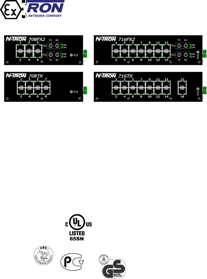
708TX, 708FX2, 708FXE2, 716TX, 716FX2, and 716FXE2 Industrial Ethernet Switch Installation Guide
The N-TRON 700 Series Industrial Ethernet Switch offers outstanding performance and ease of use. It is ideally suited for connecting Ethernet enabled industrial and or security equipment and is a fully managed switch.
PRODUCT FEATURES
•Full IEEE 802.3 Compliance
•Eight 10/100 BaseTX RJ-45 Ports (708TX)
•Six 10/100 BaseTX RJ-45 Ports and two 100BaseFX(E) Ports (708FX2 and 708FXE2 models only)
•Extended Environmental Specifications
•Autosensing 10/100BaseTX, Duplex, and MDIX
•Offers Rapid Spanning Tree Protocol
•Trunk with other N-Tron trunking capable switches over two ports
•Store & Forward Technology
•Plug and Play IGMP Support
•Rugged Din-Rail Enclosure
•Redundant Power Inputs (10-30 VDC)
o–HV High Voltage Option (40-160VDC)
•SNMP v1, v2 and v3.
•Web Browser Management with detailed ring map and fault location charting.
•Web Browsing and N-View Switch Monitoring
REGULATORY CERTIFICATIONS
II 3 G
708 Series only |
708 Series only |
|
|
PRODUCT CONFIGURATIONS
• 708TX – Eight 10/100 Base-TX RJ45 Copper Ports
•708FX2-XX – Six 10/100 Base-TX RJ45 Copper Ports, two multimode 100BaseFX Ports
•708FXE2-XX-YY – Six 10/100 Base-TX RJ45 Copper Ports, two
singlemode 100BaseFX Ports
• 716TX-VV – Sixteen 10/100 Base-TX RJ45 Copper Ports
•716FX2-XX-VV – Fourteen 10/100 Base-TX RJ45 Copper Ports, two multimode 100BaseFX Ports
•716FXE2-XX-YY-VV – Fourteen 10/100 Base-TX RJ45 Copper Ports, two singlemode 100BaseFX Ports
Where: XX = ST or SC; YY = 10, 40 or 80 for Singlemode, Blank for Multimode; E = Singlemode, Blank Otherwise; VV = HV for High voltage, Blank for Standard voltage
MANAGEMENT FEATURES
•IGMP Snooping
•VLAN
•QoS
•Trunking
•Mirroring
•LLDP
•CIP
•802.1D-2004 Rapid Spanning Tree
•N-RING™ (N-Tron proprietary Ring Management)
•N-LINK™ (N-Tron proprietary Coupling Management)
•DHCP Server, Option 82 relay
•Port Security—MAC Address Based
716-HV Models Only
(Revised 2013-06-21) |
Page 4 of 154 |
Copyright, © N-Tron Corp., 2008-2009
820 S. University Blvd., Suite 4E
Mobile, AL 36609 USA
All rights reserved. Reproduction, adaptation, or translation without prior written permission from N-Tron Corp. is prohibited, except as allowed under copyright laws.
Ethernet is a registered trademark of Xerox Corporation. All other product names, company names, logos or other designations mentioned herein are trademarks of their respective owners.
The information contained in this document is subject to change without notice. N-Tron Corp. makes no warranty of any kind with regard to this material, including, but not limited to, the implied warranties of merchantability or fitness for a particular purpose. In no event shall N-Tron Corp. be liable for any incidental, special, indirect or consequential damages whatsoever included but not limited to lost profits arising out of errors or omissions in this manual or the information contained herein.
Warning
Do not perform any services on the unit unless qualified to do so. Do not substitute unauthorized parts or make unauthorized modifications to the unit.
Do not operate the unit with the top cover removed, as this could create a shock or fire hazard.
Do not block the air vents on the sides or the top of the unit.
Do not operate the equipment in the presence of flammable gasses or fumes. Operating electrical equipment in such an environment constitutes a definite safety hazard.
Do not operate the equipment in a manner not specified by this manual.
Do not service the equipment without first disconnecting the power connector.
(Revised 2013-06-21) |
Page 5 of 154 |

SAFETY WARNINGS
GENERAL SAFETY WARNINGS
WARNING: If the equipment is used in the manner not specified by N-Tron Corp., the protection provided by the equipment may be impaired.
WARNING: Do not service the equipment without first disconnecting the power connector.
LASER SAFETY (708FXE2 Models -40, -80, 716FXE2 Models -40, -80)
CAUTION: CLASS 1 LASER PRODUCT. Do not stare into the laser!
Contact Information
N-Tron Corporation
3101 International Drive, Building 6 Mobile, AL 36606
TEL: (251) 342-2164
FAX: (251) 342-6353 WEBSITE: www.n-tron.com
E-MAIL: N-TRON_Support@n-tron.com
ENVIRONMENTAL SAFETY
WARNING: Disconnect the power and allow to cool 5 minutes before touching.
ELECTRICAL SAFETY
Power must be supplied by an isolating source and a UL-rated in-line 2.5A fuse must be installed immediately before the unit.
Must be used with listed UL Industrial Power Supply.
WARNING: Disconnect the power cable before removing the top cover.
WARNING: Do not operate the unit with the any cover removed.
WARNING: Properly ground the unit before connecting anything else to the unit. Units not properly grounded may result in a safety risk and could be hazardous and may void the warranty. See the grounding technique section of this user manual for proper ways to ground the unit.
(Revised 2013-06-21) |
Page 6 of 154 |

WARNING: Do not work on equipment or cables during periods of lightning activity.
WARNING: Do not perform any services on the unit unless qualified to do so and then only after disconnecting the power connection.
WARNING: Do not block the air vents.
WARNING: Observe proper DC Voltage polarity when installing power input cables. Reversing voltage polarity can cause permanent damage to the unit and void the warranty.
Hazardous Location Installation Requirements (Standard Voltage Models)
1.This equipment is suitable for use in Class I, Div. 2, Groups A, B, C, D or non-hazardous locations only.
2.WARNING: Explosion Hazard – Substitution of components may impair suitability for Class I, Div. 2.
3.WARNING: Explosion Hazard - do not disconnect while circuit is live, unless area is known to be non-hazardous.
4.WARNING: Explosion Hazard – do not replace the device unless power has been switched off or the area is known to be non-hazardous.
5.Use 60/75°C rated Copper wire for 708 and 90°C or higher for 716, (0.22Nm) 2lb/in Tightening torque for field installed conductors.
Please make sure the 700 Series Ethernet Switch package contains the following items:
1.700 Series Switch
2.Product CD
Contact your carrier if any items are damaged.
Installation
Read the following warning before beginning the installation:
WARNING
Never install or work on electrical equipment or cabling during periods of lightning activity. Never connect or disconnect power when hazardous gasses are present.
Disconnect the power cable before removing any enclosure panel.
(Revised 2013-06-21) |
Page 7 of 154 |
UNPACKING
Remove all the equipment from the packaging, and store the packaging in a safe place. File any damage claims with the carrier.
CLEANING - Clean only with a damp cloth.
(Revised 2013-06-21) |
Page 8 of 154 |
ATEX Installation Requirements (708 Series Only)
1.The conductor size of the phase conductor must be in the range of 16-28AWG (0.08mm²-1.31mm²).
2.Field wiring must be suitable for a minimum of 110°C.
3.Ethernet Switches are intended for mounting in an ATEX-Certified IP54 enclosure in a pollution degree 2 environments as defined by IEC 60664-1.
 II 3 G
4.Temperature testing of the Ethernet Switches was conducted on the switch itself in an 85°C aircirculating oven and resulted in a Temperature Code of T4. However, end-product temperature testing shall be considered.
5.The end user shall provide bonding means as necessary. All bonding equipment (components) shall be evaluated according to EN 60079-15:2010 and covered by a component certificate for the actual use. When installing bonding components that will pass through an enclosure wall, they must have a minimum of IP54 rating equal to the enclosure. All electrical clearances must be maintained per the manufacturer’s instructions of the bonding component or per EN 6007915:2010.
6.Ethernet Switch requires protection against transients. The end-product shall provide a suitable form of protection that removes the risk of or limits transients to no more than 42V.
7.Products are evaluated to EN 60079-0:2012 and EN 60079-15:2010.
(Revised 2013-06-21) |
Page 9 of 154 |
DIN RAIL MOUNTING FOR 708TX AND 708FX2 SERIES
Install the unit on a standard 35mm Din-Rail. Recess the 708TX unit to allow at least 3” of horizontal clearance for copper cable bend radius. Recess the 708FX2 unit to allow at least 5” of horizontal clearance for fiber cable bend radius.
Vertical Mounting |
Horizontal Mounting |
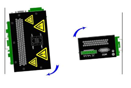
To mount the unit vertically to the 35mm DINRail, place the top edge of the bracket on the back of the unit against the DIN-Rail's top edge at an upward angle. Then, rotate the unit downward and back against the DIN-Rail until it snaps into place.
To remove the vertically mounted unit from 35mm DIN-Rail, carefully apply downward pressure on the unit. Then, rotate the unit upward and away from the 35mm DIN-Rail and lift up for removal.
To mount the unit horizontally to the 35mm DIN-Rail, place the bottom edge of the bracket on the back of the unit against the DIN-Rail's bottom edge at a downward angle. Then, rotate the unit upward and back against the DIN-Rail until it snaps into place.
To remove the horizontally mounted unit from 35mm DIN-Rail, carefully apply upward pressure on the unit. Then, rotate the unit downward and away from the 35mm DIN-Rail and lower it for removal.
(Revised 2013-06-21) |
Page 10 of 154 |
DIN RAIL MOUNTING FOR 716TX AND 716FX2 SERIES
Install the unit on a standard 35mm Din-Rail. Recess the 716TX unit to allow at least 3” of horizontal clearance for copper cable bend radius. Recess the 716FX2 unit to allow at least 5” of horizontal clearance for fiber cable bend radius. There should be at least 4” of clearance on both the top and bottom of the unit to allow proper ventilation.
To mount the unit to the 35mm din-rail, place top edge of the bracket on the back of the unit against the dinrail at an upward angle. Lower the bottom of the unit until it snaps into place.
Note: When mounting the switch in the vertical position, you must orientate the power connector to the top as shown above for proper ventilation.
OPTIONAL MOUNTING:
Most N-Tron™ products are designed to be mounted on industry standard 35mm DINRail. However, DIN-Rail mounting may not be suitable for all applications.
Our Universal Rack Mount Kit (P/N:
URMK) may be used to mount the 700
Series to standard 19" racks as an option.
Our Panel Mount Assembly (P/N: 700-PM) may be used to securely mount the 700 Series to flat surfaces or panels as an option.
(Revised 2013-06-21) |
Page 11 of 154 |
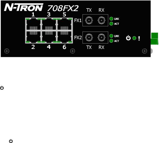
FRONT PANEL
From Top to Left: |
|
RJ45 Ports |
Auto Sensing 10/100 Base-TX Connections |
Fiber Ports |
100 Base-FX Connections (only on 708FX2 model) |
|
LED lights when Power is supplied to the unit |
NOTE: The RJ45 data port has two LEDs located on each connector. The left LED indicates LINK status, and the right LED indicates ACTIVITY.
LEDs: The table below describes the operating modes:
LED |
Color |
Description |
|
|
GREEN |
Power is ON |
|
|
|
|
|
|
RED |
Power is ON and a fault condition exists |
|
|
|
|
|
|
OFF |
Power is OFF |
|
|
|
|
|
LNK |
GREEN |
10/100Mb Link between ports |
|
|
|
||
OFF |
No Link between ports |
||
|
|||
|
|
|
|
ACT |
GREEN |
Data is active between ports |
|
|
|
||
OFF |
Data is inactive between ports |
||
|
|||
|
|
|
(Revised 2013-06-21) |
Page 12 of 154 |
APPLYING POWER (Side View)
Unscrew & Remove the DC Voltage Input Plug from the Power Input Header
Install the DC Power Cables into the Plug (observing polarity).
Plug the Voltage Input Plug back into the Power Input Header. This is the power disconnect device that must be removed before performing any kind of service or maintenance on the device.
Tightening torque for the terminal block power plug is 0.5 Nm/0.368 Pound Foot.
Verify the Power LED stays ON (GREEN).
Notes:
Only 1 power supply must be connected to power for minimal operation. For redundant power
operation, V1 and V2 inputs must be connected to separate DC Voltage sources. This device will draw current from both sources simultaneously. Use 16-28AWG (0.08mm²-1.31mm²) wire when connecting to the power supply.
The Fault pins on the power connector can be used for an alarm contact. The current carrying capacity is 1A at 24VDC. It is normally open and the relay closes when a fault condition occurs. These pins can be used to connect an external warning device such as a light in order to provide an external alarm. The conditions for generating a fault condition (closing the relay) can be configured through software.
Recommended 24V DC Power Supplies (Standard Voltage Models), similar to:
N-Tron’s P/N NTPS-24-1.3:
|
Input AC 115/230V |
|
Power 30W |
|
Output DC 24-28V |
35 mm DIN-Rail Mountable |
|
Output Current 1.3A @ 24V |
|
Dimensions: 45X75X91 mm |
|
|
1.0A @ 28V |
|
|
(Revised 2013-06-21) |
Page 13 of 154 |
Connecting the Unit
For FX/FXE units, remove the dust cap from the fiber optic connectors and connect the fiber optic cables. The TX port on the FX/FXE models should be connected to the RX port of the far end station. The RX port on the FX/FXE versions should be connected to the TX port of the far end station.
For 10/100 Base-TX ports, plug a Category 5E twisted pair cable into the RJ45 connector. Connect the other end to the far end station. Verify that the LNK LEDs are ON once the connection has been completed. To connect any port to another device (end node, Switch or Repeater), use a standard Category 5E straight through or crossover cable with a
minimum length of one meter and a maximum length of 100 meters.
N-Tron recommends the use of premanufactured Cat5E cables to ensure the best performance. If this is not an option and users must terminate their own ends on the Cat5E cables; one of the two color coded standards shown to the right should be utilized. If a user does not follow one of these two color code standards then the performance and maximum cable distance will be reduced significantly, and may prevent the switch from establishing a link.
Warning: Creating a port to port connection on the same switch (i.e. loop) is an illegal operation and will create a broadcast storm which will crash the network!
(Revised 2013-06-21) |
Page 14 of 154 |
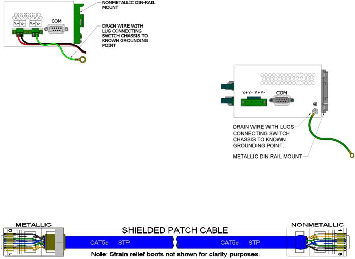
N-TRON SWITCH GROUNDING TECHNIQUES
The grounding philosophy of any control system is an integral part of the design. N-Tron switches are designed to be grounded, but the user has been given the flexibility to float the switch when required. The best noise immunity and emissions (i.e. CE) are obtained when the N-Tron switch chassis is connected to earth ground via a drain wire (20 gauge minimum size wire). Some N-Tron switches have metal din-rail brackets that can ground the switch if the din-rail is grounded. In some cases, N-Tron switches with metal brackets can be supplied with optional plastic brackets if isolation is required.
Both V- legs of the power input connector are connected to chassis internally on the PCB. Connecting a drain wire to earth ground from one of the V- terminal plugs as shown here will ground the switch and the chassis. The power leads from the power source should be limited to 3 meters or less in length.
As an alternate, users can run a drain wire & lug from any of the Din-Rail screws or empty PEM nuts on the enclosure. When using an unused PEM nut to connect a ground lug via a machine screw, care should be taken to limit the penetration of the outer skin by less than 1/4 in (NOTE: Recommend #6 32X1/4" Phillips pan head zinc screw). Failure to do so may cause irreversible damage to the internal components of the switch.
Note: Before applying power to the grounded switch, you must use a volt meter to verify there is no voltage difference between the power supply’s negative output terminal and the switch chassis grounding point.
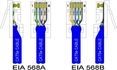
If the use of shielded cables is required, it is generally recommended to only connect the shield at one end to prevent ground loops and interfere with low level signals (i.e. thermocouples, RTD, etc.). Cat5e cables manufactured to EIA-568A or 568B specifications are required for use with N-Tron Switches.
In the event all Cat5e patch cable distances are small (i.e. All Ethernet devices are located in the same local cabinet and/or referenced to the same earth ground), it is permissible to use fully shielded cables terminated to chassis ground at both ends in systems void of low level analog signals.
(Revised 2013-06-21) |
Page 15 of 154 |
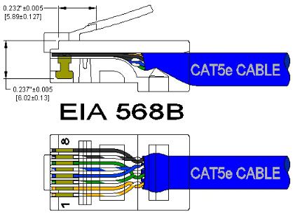
RJ45 CONNECTOR CRIMP SPECIFICATIONS
Please reference the illustration below for your Cat5 cable specifications:
(Revised 2013-06-21) |
Page 16 of 154 |
SERIAL INTERFACE
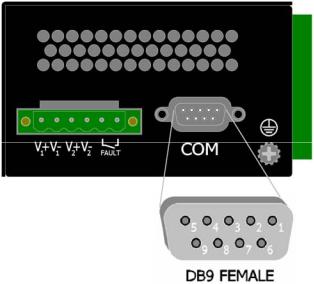
The 700 Series switches provide an EIA-232 interface accessed via a 9-pin female connector (labeled ‘COM’ on the unit). This is used to access the Command Line Interpreter (CLI). The pin-outs are shown below:
Serial Cable
Connect the serial COM port of your PC and the 700 Series Switch using a standard straight through serial cable. You will require a cable with a 9-pin or 25-pin sub-D female connector for the PC end, and a 9-pin male sub-D connector for the 708 Series end.
The following table shows the pin-out and the connections for both types of cable:
PC Port |
25-Pin |
9-Pin |
|
700 Series |
|
|
Female |
Female |
|
9-Pin Male |
|
Signal Name |
Pin # |
Pin # |
Pin # |
|
Signal Name |
TXD |
2 |
3 |
3 |
|
RXD |
RXD |
3 |
2 |
2 |
|
TXD |
GND |
7 |
5 |
5 |
|
GND |
Standard straight through serial cables are readily available from Radio Shack or a variety of computer stores.
HyperTerminal
The following configuration should be used in HyperTerminal:
Port Settings: |
115200 |
Data Bits: |
8 |
Parity: |
NONE |
Stop bits: |
1 |
Flow Control: |
NONE |
(Revised 2013-06-21) |
Page 17 of 154 |
Overview of Advanced Features
Mode of Operation
Each port on the switch can be configured into different modes of operation as shown below:
Copper Ports: |
100Base Fiber Ports: |
- Half Duplex |
- Full Duplex |
-Full Duplex
-Auto Negotiation
Half Duplex
In half duplex mode, the CSMA/CD media access method is the means by which two or more stations share a common transmission medium. To transmit, a station waits (defers) for a quiet period on the medium (that is, no other station is transmitting) and then sends the intended message in bit-serial form. If, after initiating a transmission, the message collides with that of another station, then each transmitting station intentionally transmits for an additional predefined period to ensure propagation of the collision throughout the system. The station remains silent for a random amount of time (back-off) before attempting to transmit again.
Full Duplex
Full duplex operation allows simultaneous communication between a pair of stations using point-to-point media (dedicated channel). Full duplex operation does not require that transmitters defer, nor do they monitor or react to receive activity, as there is no contention for a shared medium in this mode.
Auto Negotiation
In Auto Negotiation mode, the port / hardware detects the mode of operation of the station that is connected to this port and sets its mode to match the mode of the station.
Port Mirroring
A Mirroring Port is a dedicated port that is configured to receive the copies of Ethernet frames that are being transmitted out and also being received in from any other port that is being monitored.
Port Trunking
Port Trunking is the ability to group two network ports to increase the bandwidth between two machines (switch or any work station). This feature allows grouping of high-speed connectivity and provides redundant connection between switches, so that a trunk can act as a single link between the switches.
Quality of Service (QoS)
Quality of service (QoS) refers to resource reservation control mechanisms. Quality of service is the ability to provide different priority to different applications, users, or data flows. Quality of service guarantees are important if the network capacity is insufficient, especially for real-time streaming multimedia applications such as voice over IP, online games and IP-TV, since these often require fixed bit rate and are delay sensitive, and in networks where the capacity is a limited resource, for example in cellular data communication. In the absence of network congestion, QoS mechanisms are not required.
(Revised 2013-06-21) |
Page 18 of 154 |
Each of these three QOS methods below is included or not based on the settings on the relevant browser page:
1)Force High Priority (Port Based),
2)IEEE802.1p (Tagged QOS), or
3)DSCP (differentiated services code points) (RFC 2474).
When Force High Priority is enabled, the port based priority is included in the decision for all ports and all frames received on a port will use the default QOS priority for that port in the decision. For example, if it is desired to have ingress frames on a port egress to the highest priority transmit queue regardless of other factors, then enable Force High Priority and set the port's Default Port Priority to 7.
Virtual LAN
The switch provides support for setting up tagged Virtual LANs (Local Area Networks). A port may belong to any number of Virtual LANs. The VLAN membership of a device is determined by the VLAN(s) that have been defined for the port to which the device is connected. If a device should move from one port to another, it loses its current VLAN membership and inherits that of the new port it is connected to.
VLANs facilitate easy administration of logical groups of devices that can communicate as if they
were on the same LAN. Traffic between VLANs is restricted, unless the ports are explicitly configured as overlapping VLANs. Switches forward unicast, multicast, and broadcast traffic only on LAN segments that serve the VLAN to which the traffic belongs.
A Default Virtual LAN (VID=1) exists to which a port, which is not a member of any other Virtual LAN, will belong. This allows the switch to operate as a ‘normal’ switch when it is used in a network. A port is automatically removed from the Default VLAN when it is reconfigured to belong to another Virtual LAN, because that is the most common operation. But, if desired, the port can be included in VLAN 1 by configuring VLAN 1 last.
If switch ports are configured to transmit and receive untagged frames, end devices are able to communicate throughout the LAN. Using Tagged VLANs, the switch has the ability to take non-tagged packets in some ports, add a VLAN tag to the packet and send it out tagged ports on the switch. The VLANs can also be configured to accept tagged packets in tagged ports, strip the tags off the packets, and send the packets back out other untagged ports. This allows a network administrator to set up the switch to support devices on the network that do not support VLAN Tagged packets. The administrator can also set up the ports to discard any packets that are tagged or to discard any packets that are untagged based on a hybrid VLAN of both tagged and untagged ports, and using the VLAN Ingress Filter on the switch.
For each switch port there is one and only one PVID (port VLAN ID) setting. If an incoming frame is untagged and untagged frames are being accepted, then that frame will inherit the tag of the PVID value for that port. Subsequent switch routing and treatment will be in accordance with that VLAN switch map. By configuring PVIDs properly and configuring for all frames to exit untagged, the switch can achieve a ‘port VLAN’ configuration in which all frames in and out can be untagged, thus not requiring external devices to be VLAN cognizant.
To understand how a VLAN configuration will perform, first look at the port on which the frame enters the switch, then the VLAN ID (if the frame is tagged) or the PVID (if the frame is untagged). The VLAN defined by the VID or PVID defines a VLAN group with a membership of ports. This membership determines whether a port is included or excluded as to frame egress from the switch.
The 700 Series switch also has the ability to allow overlapping VLANs. Overlapping VLANs give the user
(Revised 2013-06-21) |
Page 19 of 154 |
the ability to have one or more ports share two or more VLAN groups. For more information and examples on how this could be implemented, please see the ‘VLAN Configuration Examples’ in this document, and/or our website’s technical documents. Note that RSTP on overlapping VLANs is not supported and the system will automatically disable RSTP on all but the lowest VID VLANs that have overlapping ports.
Rapid Spanning Tree Protocol
The Rapid Spanning Tree Protocol as specified in IEEE 802.1D-2004 is supported. One Spanning Tree per non-overlapping VLAN is supported. The Rapid Spanning Tree Protocol (RSTP) supersedes the Spanning Tree Protocol (STP) which was described in IEEE 802.1D-1998. The RSTP is used to configure a simply connected active network topology from the arbitrarily connected bridges of a bridged network. Bridges effectively connect just the LANs to which their forwarding ports are attached. Ports that are in a blocking state do not forward frames. The bridges in the network exchange sufficient information to automatically derive a spanning tree.
RSTP allows for much quicker learning of network topology changes than the older STP. RSTP supports new and improved features such as rapid transition to forwarding state. RSTP also sends out new BPDUs every hello time instead of just relaying them. RSTP interoperates with older STP switches by falling back to the older STP when the older BPDUs are detected on bridge ports. The user can also manually configure bridge ports to use the older STP when desired.
SNMP Traps
The 700 Series switch supports up to 5 SNMP Trap Stations to which SNMP Traps will be sent. The switch supports four standard traps; Link Up, Link Down, Cold Start and Warm Start. SNMP Traps will be sent to all the stations configured on the switch if a port Link goes up or down, when the switch first powers up and when the switch is reset.
IGMP Snooping
IGMP Snooping is enabled by default, and the switch is Plug and Play for IGMP. IGMP snooping provides intelligent network support for multicast applications. In particular, unneeded traffic is reduced. IGMP Snooping is configured via the web console and if enabled, operates dynamically upon each power up. Also, there can be manual only or manual and dynamic operation. Note that “static multicast group address” can be used whether IGMP Snooping is enabled or not.
IGMP Snooping will function dynamically without user intervention. If some of the devices in the LAN do not understand IGMP, then manual settings are provided to accommodate them. The Internet Group Management Protocol (IGMP) is a protocol that provides a way for a computer to report its multicast group membership to adjacent ‘routers’. In this case N-Tron 700 Series switches provide router-like functionality. Multicasting allows one computer to send content to multiple other computers that have identified themselves as interested in receiving the originating computer's content. Multicasting can be used to transmit only to an audience that has joined (and not left) a multicast group membership. IGMP version 2 is formally described in the Internet Engineering Task Force (IETF) Request for Comments (RFC) 2236. IGMP version 1 is formally described in the Internet Engineering Task Force (IETF) Request for Comments (RFC) 1112. The 700 Series supports v1 and v2.
N-Ring
N-Ring is enabled by default, and the switch is Plug and Play for N-Ring except that initially one must enable an N-Ring enabled device to be the N-Ring Manager for a given N-Ring. Subsequently, N-Ring
(Revised 2013-06-21) |
Page 20 of 154 |
operates dynamically upon each power up. Using N-Tron's proprietary N-Ring technology offers expanded ring size capacity, detailed fault diagnostics, and a standard healing time of 30ms. The N-Ring Manager periodically checks the health of the N-Ring via health check packets. If the N-Ring Manager stops receiving the health check packets, it times out and converts the N-Ring to a backbone within 30ms. When using all N-Ring enabled switches in the ring, a detailed ring map and fault location chart is also provided on the N-Ring Manager’s web browser. N-Ring status is also sent from the N-Ring Manager to the N-View OPC Server to identify the health status of the ring. Up to 250 N-Ring enabled switches can participate in one N-Ring topology. Switches that do not have N-Ring capability may be used in an N-Ring, however the ring map and fault location chart cannot be as detailed at these locations.
N-Link
The purpose of N-Link is to provide a way to redundantly couple an N-Ring topology to one or more other topologies, usually other N-Ring topologies. Each N-Link configuration requires 4 switches: N-Link Master, N-Link Slave, N-Link Primary Coupler, and N-Link Standby Coupler. N-Link will monitor the link status of the Primary and Standby Coupler links. While the Primary Coupler link is healthy, it will forward network traffic and the Standby Coupler link will block network traffic. When a problem is detected on the Primary Coupler link, the Primary Coupler link will block network traffic and the Standby Coupler link will forward network traffic. While the N-Link Master and Slave are in communication via the Control link, only one Coupler link (Primary or Standby) will forward network traffic while the other Coupler link will block network traffic.
CIP
The CIP (Common Industrial Protocol) feature allows N-Tron switches to directly provide switch information and configuration access to Programmable Logic Controller (PLC) and Human Machine Interface (HMI) applications via a standardized communication protocol. For example, a PLC may be programmed to monitor port links or N-Ring status and cause a status indicator to turn red on an HMI if a port goes link down or if N-Ring has a fault. CIP is formally described in ODVA Publication Number PUB00001 (Volume 1: Common Industrial Protocol (CIP™)), and Publication Number: PUB00002 (Volume 2: Ethernet/IP Adaptation of CIP). N-Tron provides EDS and ICO files. N-TRON_CIP_Tags.pdf is for a particular environment, but reveals the tags available.
DHCP
The Dynamic Host Configuration Protocol (DHCP) provides configuration parameters to Internet hosts. DHCP is built on a client-server model, where designated DHCP server hosts allocate network addresses and deliver configuration parameters to dynamically configured hosts. DHCP is controlled by RFC 2131. The N-Tron DHCP Switch can be configured to be a DHCP Client. Alternately the N-Tron DHCP switch can be configured to be a DHCP Server, a DHCP Relay Agent, or both.
For more detailed information on N-Tron DHCP features, reference: http://www.n-tron.com/tech_docs.php. Under ‘White papers’, see. “Using DHCP to Minimize Equipment Setup Time”. Under ‘Installation Guides and User Manuals’ see “DHCP Technical Instructions for 708 / 716/ 7018 / 7506 Series”.
DHCP Client
The switch will automatically obtain an IP assignment from a DHCP Server, or optionally Fallback to a configured IP assignment if unable to get an IP assignment from a DHCP server. Communication between the client and server can optionally go through a DHCP Relay Agent.
(Revised 2013-06-21) |
Page 21 of 154 |
DHCP Relay Agent
DHCP Relay Agent (Option 82) allows communication between the client and server to cross subnet and VLAN boundries. It also allows for a device on a specific port to receive a specific IP address and if the device is replaced, the replacement receives the same IP address as the original device.
DHCP Server
DHCP Server allows DHCP Client devices to automatically obtain an IP assignment. IP assignments can be set up as a dynamic range of IP addresses available to any client device; or specific IP addresses based on the clients MAC address, Client ID (Option 61), or Relay Agent connection (Option 82).
LLDP
Link Layer Discovery Protocol (LLDP) is a Layer 2 discovery protocol that allows devices attached to an IEEE802 LAN to advertise to other devices the major capabilities they have and to store information they discover in a MIB that can be accessed through SNMP. LLDP is formally described in IEEE Standard - 802.1AB.
Port Security—MAC Address Based
The Port Security feature restricts access to the switch by only accepting dynamically learned MAC addresses and manually entered MAC addresses as authorized. Dynamically learned MAC addresses are those that the switch detects on any port while in ‘Learning’ mode. A manually entered MAC address must designate the ports that the address is authorized on. A non-authorized MAC address will be discarded and will be shown on the intruder log.
(Revised 2013-06-21) |
Page 22 of 154 |
TROUBLESHOOTING
1.Make sure the  (Power LED) is ON.
2.Make sure you are supplying sufficient current for the version chosen. Note: The Inrush current will exceed the steady state current by ~ 2X.
3.Verify that Link LEDs are ON for connected ports.
4.Verify cabling used between stations.
5.Verify that cabling is Category 5E or greater for 100Mbit operation.
SUPPORT
Contact N-Tron Corp. at:
TEL: 251-342-2164
FAX: 251-342-6353
E-MAIL: N-TRON_Support@n-tron.com
WEB: www.n-tron.com
FCC STATEMENT
This product complies with Part 15 of the FCC-A Rules.
Operation is subject to the following conditions:
(1)This device may not cause harmful Interference
(2)This device must accept any interference received, including interference that may cause undesired operation.
NOTE: This equipment has been tested and found to comply with the limits for a Class A digital device, pursuant to Part 15 of the FCC Rules. These limits are designed to provide reasonable protection against harmful interference in a residential installation. This equipment generates, uses, and can radiate radio frequency energy and, if not installed and used in accordance with the instructions, may cause harmful interference to radio communications. Operation of this device in a residential area is likely to cause harmful interference in which case the user will be required to correct the interference at his/her own expense.
INDUSTRY CANADA
This Class A digital apparatus meets all requirements of the Canadian Interference Causing Equipment Regulations. Operation is subject to the following two conditions; (1) this device digital apparatus meets all requirements of the Canadian Interference Causing Equipment Regulations. Operation is subject to the following two conditions; (1) this device may not cause harmful interference, and (2) this device must accept any interference received, including interference that may cause undesired operation.
Cet appareillage numérique de la classe A répond à toutes les exigences de l'interférence canadienne causant des règlements d'équipement. L'opération est sujette aux deux conditions suivantes: (1) ce dispositif peut ne pas causer l'interférence nocive, et (2) ce dispositif doit accepter n'importe quelle interférence reçue, y compris l'interférence qui peut causer l'opération peu désirée.
(Revised 2013-06-21) |
Page 23 of 154 |
Web Software Configuration
Web Management
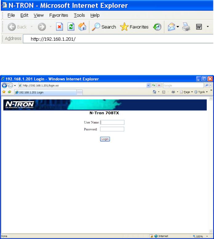
Enter the switch’s IP address in any web browser and login to the web management feature of the 700 Series.
Default:
User Name: admin
Password: admin
(Revised 2013-06-21) |
Page 24 of 154 |

Web Management - Home
When the administrator first logs onto a 700 Series switch the default home page will be displayed. On the left hand side of the screen there is a list of configurable settings that the 700 Series switch will support. This section of the manual will go through each and every choice listed on the left hand side of the screen and explain how to configure those settings. In the center of the main home page the administrator can see some basic information like what firmware revision the switch is running. The firmware can be upgraded at a later time in the field using TFTP.
(Revised 2013-06-21) |
Page 25 of 154 |
Web Management – Menu Structure
To the left, there is a menu which is shown fully opened below. The pages opened by each of the individual selections are described in the rest of this section. The use of each of these pages is also described in this section. In most of the descriptions, only the right side of the page is shown.
(Revised 2013-06-21) |
Page 26 of 154 |
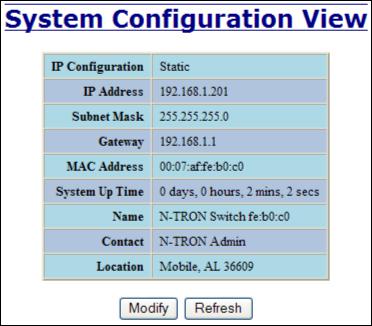
Administration – System
The System tab under the Administration category, lists various information about the switch:
When the IP Configuration is in either DHCP or Static Mode:
IP Configuration
Method used to obtain an IP Address, Subnet Mask and Gateway Address
IP Address
Contains the current IP Address of the device.
Subnet Mask
Contains the current Subnet Mask of the device.
Gateway
Contains the current Gateway of the device.
MAC Address
MAC Address of the device.
System Up Time
This parameter represents the total time count. This time has elapsed since the switch was turned ON or RESET.
Name
It shows the name of the product, which allows alphanumeric and special characters (#, _, -) only.
Contact
The person to contact for system issues, which should be someone within your organization.
Location
The physical location of the switch.
(Revised 2013-06-21) |
Page 27 of 154 |
Administration – System, Continued…
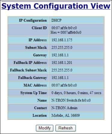
When the IP Configuration is in DHCP Mode the following information is added:
Client ID
Option used by DHCP clients to specify their unique identifier. The identifier may be the MAC address, switch name, or entered as a text string or hex characters.
Fallback IP Address
Contains the configured Fallback IP Address of the device.
Fallback Subnet Mask
Contains the configured Fallback Subnet Mask of the device.
Fallback Gateway
Contains the configured Fallback Gateway of the device.
(Revised 2013-06-21) |
Page 28 of 154 |
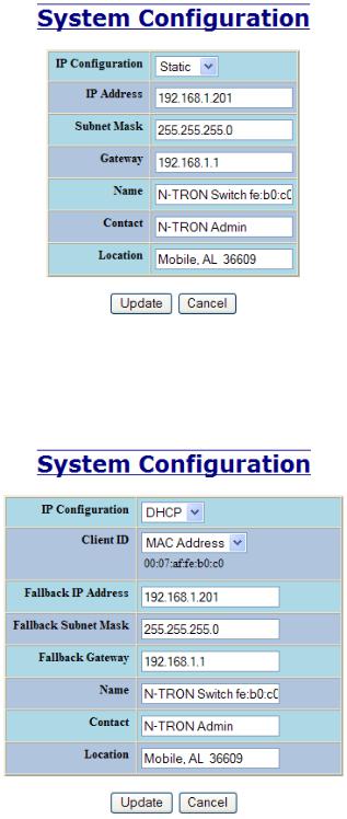
Administration – System, Continued…
By selecting the Modify button, you will be able to change the switch’s IP Configuration, Client ID, IP Address, Subnet Mask, Gateway, Name, Contact information, and the Location of the switch through the web management features, depending on the IP Configuration. It is recommended to change the TCP/IP information through the Command Line Interface (CLI) initially, but it defaults to the following:
IP Configuration |
– Static |
|
IP Address |
– 192.168.1.201 |
|
Subnet Mask |
– 255.255.255.0 |
|
Gateway |
– 192.168.1.1 |
|
|
|
|
|
|
|
If the IP Configuration mode is set to DHCP and the Fallback IP address is changed from the default IP address, then the switch will use the Fallback addresses if the IP configuration isn’t received from a DHCP server in 2 minutes after initial boot. If Fallback address is used, DHCP Client will stop sending requests. If the IP Configuration is received from a DHCP server, it will never fallback, even if the lease is lost.
(Revised 2013-06-21) |
|
Page 29 of 154 |
|
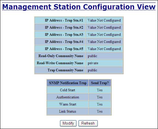
Administration – SNMP
The SNMP tab under the Administration category shows a list of IP Addresses that act as SNMP Traps. The Read-Only, Read-Write, and Trap Community Names are also shown here.
By selecting the Modify button, you will be able to change any of the fields listed. This allows the user to set an IP address for a Trap station or change the Community Names. If the SNMP Notification Trap is enabled, systems that are listed as a Trap station will be sent the corresponding notification trap. To restore a Trap to “Value Not Configured”, enter ‘0.0.0.0’.
(Revised 2013-06-21) |
Page 30 of 154 |
 Loading...