

Page 1

708, 709FX, 710FX2, 711FX3, 712FX4, 714FX6,
716, 7010TX, 7012FX2, 7018, & 7506GX2 Series
Managed Industrial
Ethernet Switch
DHCP Technical Instructions
Revision 2010-11-15 Page 1 of 33
Page 2

Contents
Contents .................................................................................................................................................................. 2
Overview ................................................................................................................................................................. 3
Configuring DHCP Server and Relay Agent .......................................................................................................... 4
Examples ................................................................................................................................................................. 4
N-Tron DHCP Setup Process – Basic Setup Flow ................................................................................................. 5
Getting connected with N-Tron DHCP Server ....................................................................................................... 6
DHCP Menu............................................................................................................................................................ 6
Figure: Menu_1 ................................................................................................................................................... 6
Enabling the DHCP Server ................................................................................................................................. 7
Setting up the DHCP Server Profiles .................................................................................................................. 7
Figure: Profile_1 .............................................................................................................................................. 7
Setting up the DHCP Server Mappings .............................................................................................................. 8
Figure: Mapping_1 .......................................................................................................................................... 8
Setting up a Dynamic Range ............................................................................................................................... 8
Topology:......................................................................................................................................................... 8
Setting up a Static Range .................................................................................................................................. 10
Basic configuration using Option 82 Relay Agent ........................................................................................ 10
Topology:....................................................................................................................................................... 10
N-Tron Relay Agent Setup Process – Basic Setup Flow .................................................................................. 12
Setup Option 82: Relay Agent Switch ........................................................................................................... 13
N-Tron DHCP Server Static Range Setup Process – Basic Setup Flow ........................................................... 14
Setup Option 82: DHCP Server Switch ......................................................................................................... 15
Setting up a Single IP ........................................................................................................................................ 17
Basic configuration using Option 61 or MAC Address ................................................................................ 17
Topology:....................................................................................................................................................... 17
Setting up an N-Tron Switch as a Client Device .................................................................................................. 19
Topology ........................................................................................................................................................... 19
Example ............................................................................................................................................................. 19
Relay Agent - Stand Alone ................................................................................................................................... 21
Setting up the Relay Agent to obtain a Local IP Address ................................................................................. 21
Topology:....................................................................................................................................................... 21
Advanced DHCP Server Topologies .................................................................................................................... 22
Setting up a redundant DHCP Server using 2 N-Rings across N-Link ............................................................. 22
Topology 1:.................................................................................................................................................... 22
Firmware/Config – TFTP ..................................................................................................................................... 29
SUPPORT ............................................................................................................................................................. 31
N-TRON Limited Warranty .................................................................................................................................. 32
Revision 2010-11-15 Page 2 of 33
Page 3

Overview
The Dynamic Host Configuration Protocol (DHCP) provides configuration parameters to Internet hosts.
DHCP consists of two components: a protocol for delivering host-specific configuration parameters from a
DHCP server to a host and a mechanism for allocation of network addresses to hosts. DHCP is built on a
client-server model, where designated DHCP server hosts allocate network addresses and deliver
configuration parameters to dynamically configured hosts. (DHCP is explained in RFC 2131).
The N-Tron DHCP Switch can be configured to be a DHCP Server, a DHCP Relay Agent, or both.
DHCP Server - manages and allocates IP address from a pool of address, defined by Profiles, to
requesting Clients.
Relay Agent – receives DHCP requests messages and directs them to a specific DHCP server.
Before sending the DHCP request, the Relay Agent appends identifying information into the
message (Circuit ID + Remote ID).
o Circuit ID – contains information that identifies the port location that the DHCP request
comes from. For example (TX1-0001) defines request came from Port 1 – VLAN 1.
o Remote ID – contains information that identifies the Relay Agent device. (For example: the
IP address or MAC address of the Relay Agent.)
It can also Assign a Local IP address when a client is connected to a specific port. Relay Agent is
explained in RFC 3046.
The N-Tron DHCP Server supports several methods of allocating IP address in a managed manner.
Dynamic Range – IP address allocation is Dynamic and is based on the first free IP address in the
defined range. The IP address could be different each time the Client makes a request.
Static Range: Option 82 Relay Agent- IP address allocation is Static and is based on matching
Option 82 information received from a Relay Agent. The same IP address will be given each time to
a specific Client.
Single IP: Option 61 or MAC - IP address allocation is Static and is based on matching Option 61
information received from a Client. The same IP address will be given each time to a specific
Client.
Revision 2010-11-15 Page 3 of 33
Page 4

Configuring DHCP Server and Relay Agent
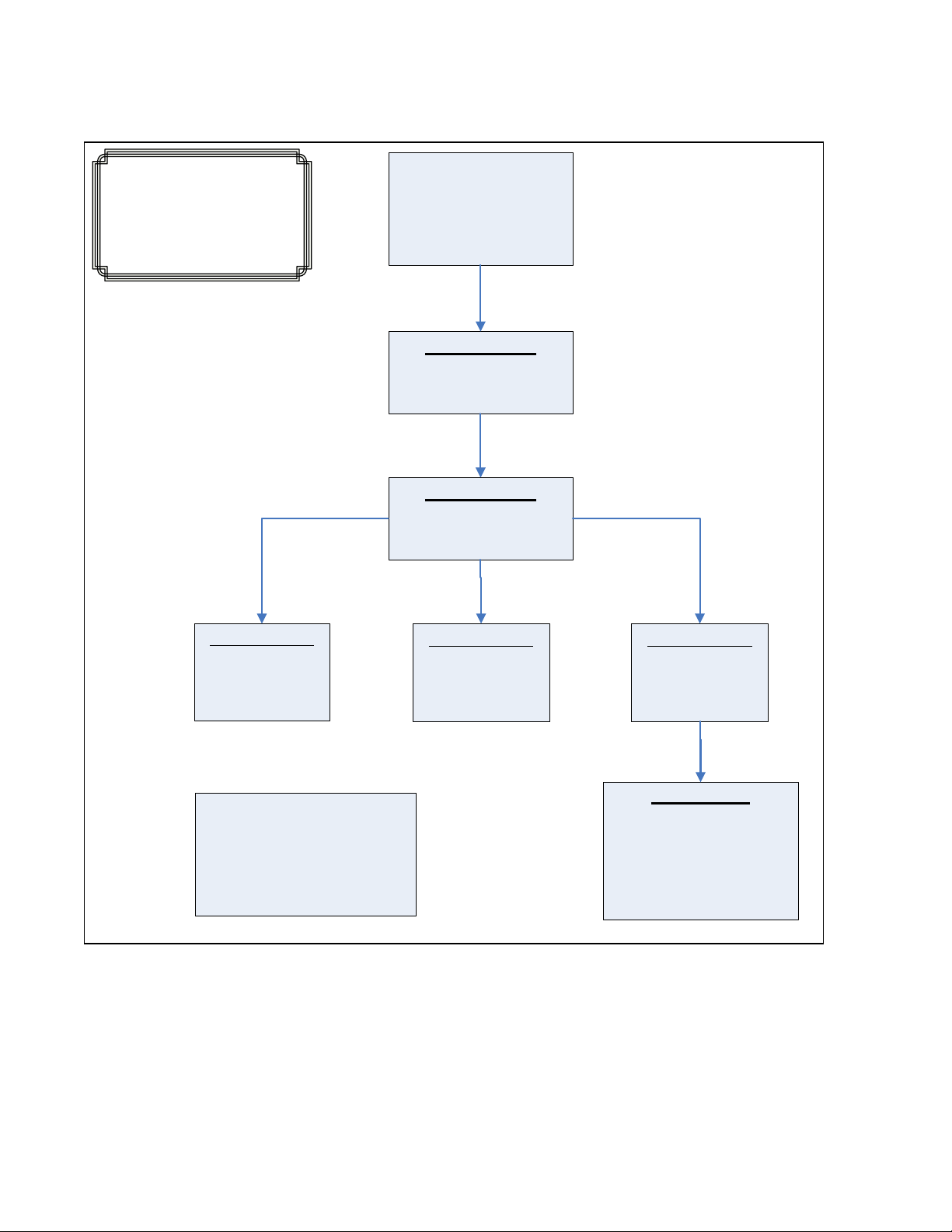
The following information will be helpful as you configure the N-Tron DHCP Server. A high level flow of
the basic configuration is provided by Figure: Flow_DHCP_1.
In order to use the DHCP server in offering IP addresses, several configuration steps are essential. N-Tron
uses Profiles and Mappings to organize how the IP’s will be offered to Clients. You must have at least one
Profile defined in order to add mappings.
The menu Setup Profiles shows DEFAULT as a Profile. The DEFAULT Profile allows you to define some
changeable parameters that are automatically included within the Profile you define. The changeable
Profile entries can be seen by pressing the, Advanced, button when adding a Profile. You do not have to
make use of this DEFAULT Profile. The DEFAULT Profile information is used by the DHCP Server when
communicating with the DHCP Client. The use of the DEFAULT Profile simplifies the changing of
information of already defined Profiles by automatically inserting data found in the DEFAULT profile into
the Profile used when allocating an IP addresses to a Client.
The Profile Setup has entries to define an Address Pool range. It is important to decide what this range
should be, since your IP address mappings will be a subset of this range. Profiles cannot overlap their
Address Pool ranges with other Profiles.
The Profile Setup Lease Time: designates the amount of time an IP will be honored by a Server that has
made an offer to a Client. The Lease Time insures that the IP address offered by the Server will not be
offered to any other Client device until the Lease expires. The Client will use a renewal process to maintain
the IP for longer periods of time by requesting an extension for the address from the server.
Saving DHCP Settings and Data: The DHCP Profiles, Mappings and Bindings are stored in the N-Tron
switch file system when you click on the screen Update button. These changes are automatically saved for
you. Parameters such as Enabling and Disabling the DHCP Server are part of the switch Settings
configuration and you will be prompted by a message to save your changes.
Examples
Examples are provided for the following settings:
Setting up a Dynamic Range
Setting up a Static Range
Setting up a Single IP
Setting up an N-Tron Switch as a Client Device
Setting up the Relay Agent to obtain a Local IP Address
Setting up a redundant DHCP Server using 2 N-Rings across N-Link
Revision 2010-11-15 Page 4 of 33
Page 5
DHCP Server
Enable DHCP
Server
DHCP Server
Setup Profiles
DHCP Server
Setup IP Maps
Relay Agent
Relay & Local IP
Setup
N-Tron Client
Switch
Setup DHCP Client
DHCP Server
Create
Dynamic Range
DHCP Server
Create
Static Range
DHCP Server
Create
Single IP
N-Tron
DHCP Setup
Process
N-Tron DHCP Setup Process – Basic Setup Flow
Figure: Flow_DHCP_1
Revision 2010-11-15 Page 5 of 33
Page 6
Getting connected with N-Tron DHCP Server
N-Tron Switches provide a Web Interface for all your DHCP configurations.
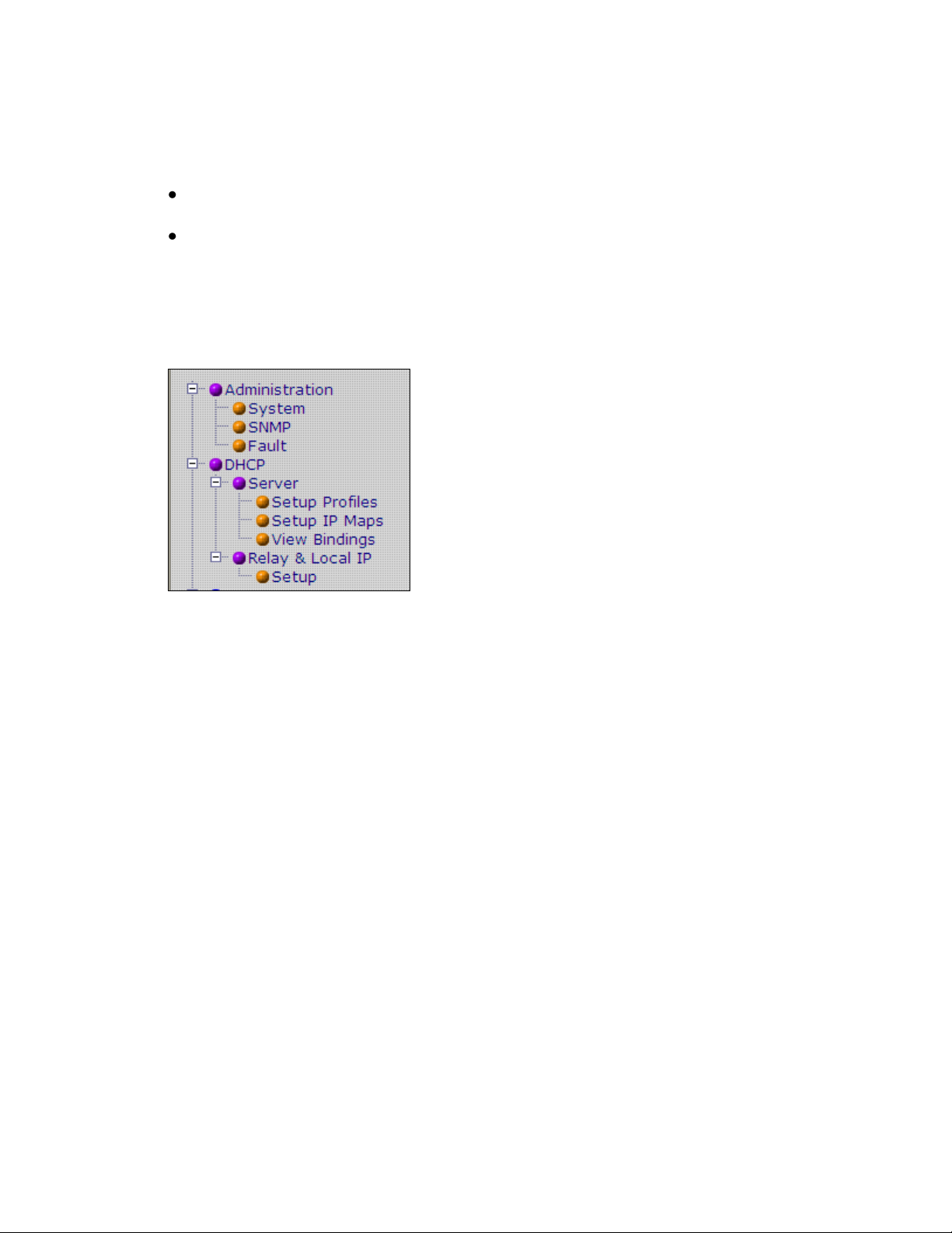
The two main menus for DHCP configuration are:
DHCP – contains the configuration for both the DHCP Server and Relay Agent.
Administration – clicking on Administration / System / IP Configuration menu, allows you to
configure the DHCP Client to be either Static or DHCP. In order to receive an IP address
from a DHCP Server the switch must be configured for DHCP.
DHCP Menu
Figure: Menu_1
Revision 2010-11-15 Page 6 of 33
Page 7
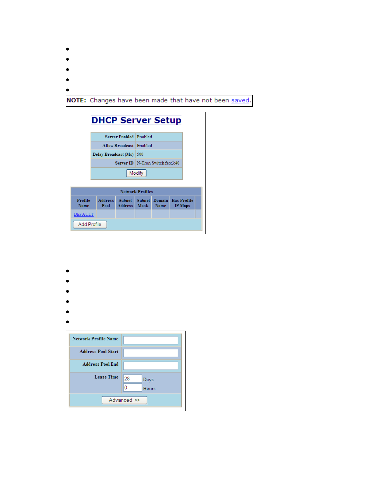
Enabling the DHCP Server
Click on: DHCP / Server / Setup Profiles. See Figure: Menu_1
Click on: Modify Button. See Figure: Setup_1
Click on Server Enabled Box and select Enabled.
Click on Update Button.
Click on Saved.
Figure: Setup_1
Setting up the DHCP Server Profiles
Click on: DHCP / Server / Setup Profiles. See Figure: Menu_1
Click on: Add Profile button. See Figure: Setup_1
Enter a Network Profile Name: Ex. One
Enter an Address Pool Start: Ex. 192.168.2.1
Enter an Address Pool End: Ex. 192.168.2.254
Click on Update when finished.
Figure: Profile_1
Revision 2010-11-15 Page 7 of 33
Page 8
Setting up the DHCP Server Mappings
DHCP
Client
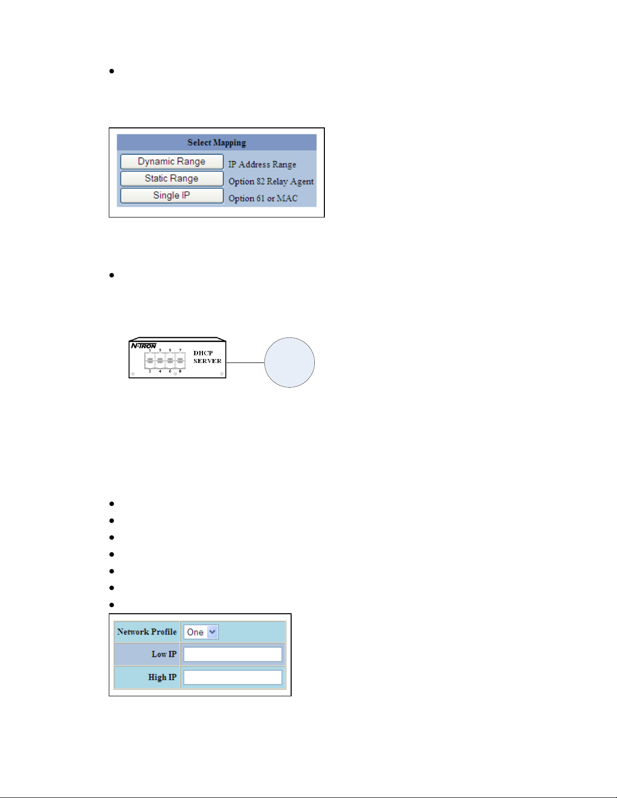
Mappings are used to define rules that are used in determining what IP address will be
offered to the client.
N-Tron provides the following Mapping Types:
Figure: Mapping_1
Setting up a Dynamic Range
IP address allocation is Dynamic and is based on the first free IP address in the defined
range. The IP address could be different each time the Client makes a request.
Topology:
Example:
In this example connections can be made to any port on the server or on a switch connected to the
server. The IP address given will be the next available address in the range defined.
Setup:
Click on: DHCP / Server / Setup IP Maps. See Figure: Menu_1
Click on: Dynamic Range. See Figure: Mapping_1
Reference Figure: Dynamic_1 below.
Select the Profile you wish to add this mapping too.
Enter Low IP: Ex. 192.168.2.25
Enter High IP: Ex. 192.168.2.35
Click Update when finished.
Figure: Dynamic_1
Revision 2010-11-15 Page 8 of 33
Page 9
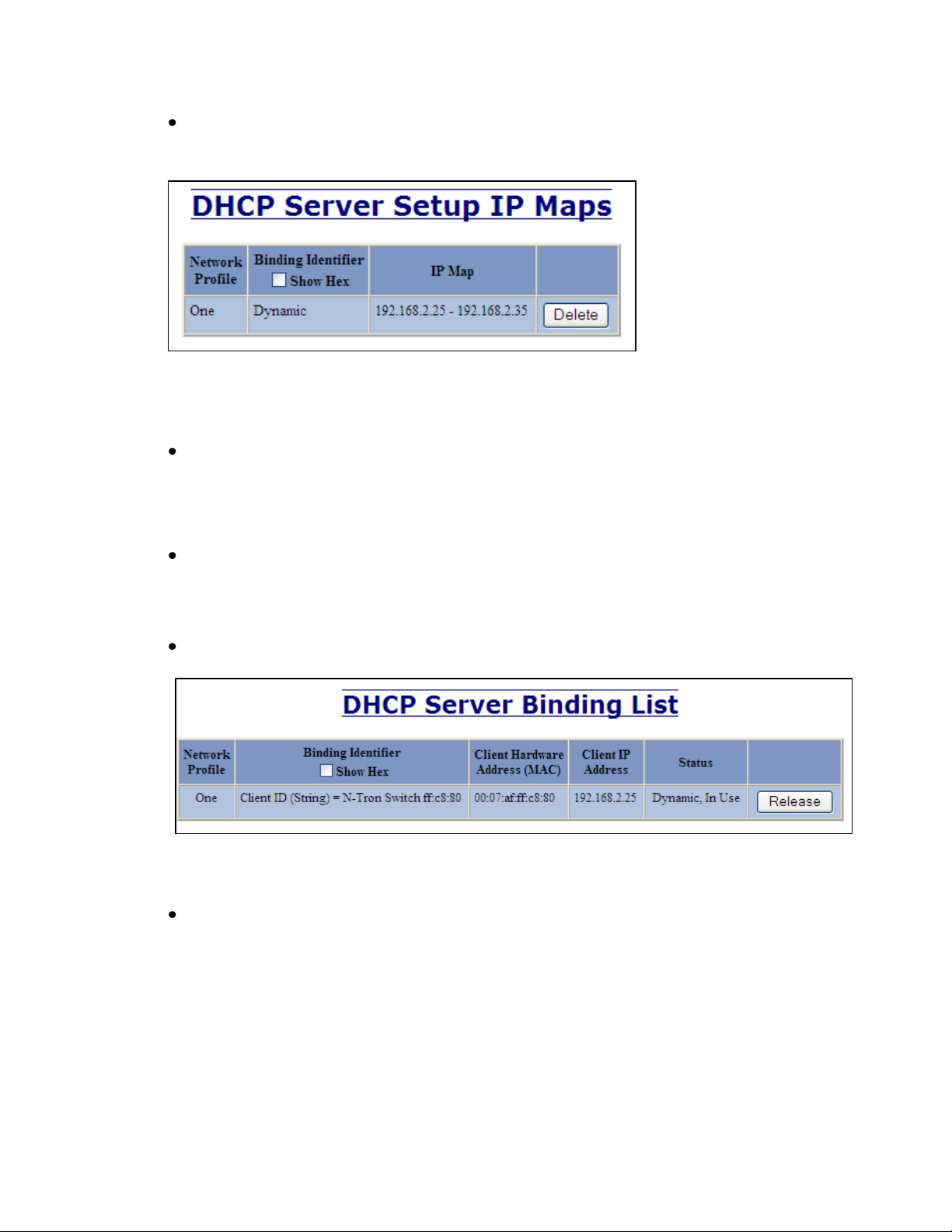
Mapping:
The resulting mapping from the setup can be viewed by clicking on DHCP / Server / Setup
IP Maps. See Figure: Dynamic_2 below.
Figure: Dynamic_2
Connection:
Connect the Ethernet cable to the device and to a port on the Server.
Powering On and Status Display:
Power on the client device. The device will request an IP address from the Server. The
Server will offer the client an IP address from the dynamic range. Allow 20 - 30seconds for
the DHCP transactions to finalize.
To view status: Click on DHCP / Server / View Bindings
Figure: Dynamic_3
The Web browser can now be used to view and configure the client device.
Revision 2010-11-15 Page 9 of 33
Page 10
Setting up a Static Range
TX1
192.168.2.100
Using a static IP address enables the DHCP Server to assign a DHCP Client the same IP
address each time the device is connected to a designated port on a Relay Agent.
Basic configuration using Option 82 Relay Agent
The setup for this method is a 2 step process and will be described below.
The first step is to setup the Relay Agent. See Setup Option 82: DHCP Server Switch.
The second step is to setup the DHCP Server. See Setup Option 82: DHCP Server Switch.
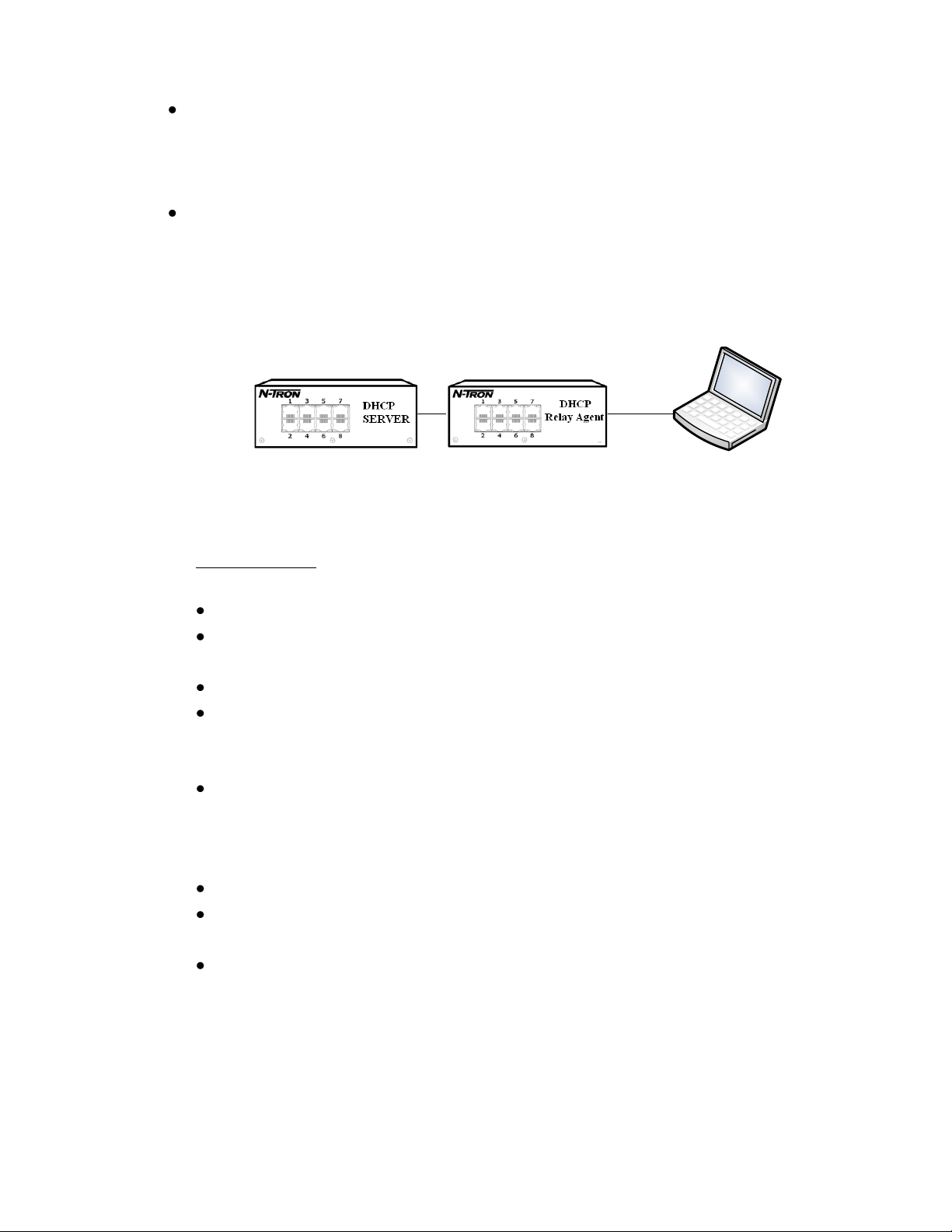
Topology:
Example : A connection is made from the Client to a designated port (TX1) on the Relay
Agent.
In this example:
Make configuration on the Relay Agent. See Figure: Option82_1
The Relay Agent has been enabled.
The address of the DHCP server has been specified in the DHCP Server 1 IP as
192.168.2.213.
The Remote ID selected is the IP address of the Relay Agent.
The Relay Status has been enabled. This specifies that the relay agent should send a
request for an IP on behalf of the Client when the Client is connected to port TX1 and
that the VLAN the request will be using is 1.
The default string information provided in the field Other Data will be used (TX1-0001).
Configuration on the Server side should match the configuration on the Relay Agent: See
Figure: Option82_2
The Remote ID’s and Circuit ID’s are the same for the Port selected.
When a request for an IP arrives to the DHCP Server from the Relay Agent, the DHCP
Server will compare the Remote and Circuit ID’s and if they match, an IP will be offered.
In this case the Client will receive the IP address 192.168.2.100.
Revision 2010-11-15 Page 10 of 33
Page 11

Notes:
Other Data : Circuit ID
There are four formats you can use to enter Circuit ID data.
Hex, MAC, IP and String
The default string has particular meaning to an N-Tron Server switch:
(Port-VLAN). For example TX1-0001.
Entering string data in any other format will require you to use the Relay
Agent Type : Generic when configuring the DHCP Server. See Figure:
Option82_2.
Revision 2010-11-15 Page 11 of 33
Page 12

Select Port:
Select:
Relay Status
Enable
Relay
Status
Disabled Assign Local IP
Enabled
Create
Circuit ID
Input Formts:
Hex String
MAC Address
IP Address
Text String
Update
Create
Remote ID
Input Formts:
IP Address
MAC Address
Client ID
Other String
Other Hex
N-Tron DHCP
Relay Agent & Local IP
Setup
N-Tron Relay Agent Setup Process – Basic Setup Flow
Figure: Flow_Relay_Static_Range
Revision 2010-11-15 Page 12 of 33
Page 13

Setup Option 82: Relay Agent Switch
Click on: DHCP / Relay & Local IP / Setup. See Figure: Menu_1
Reference Figure: Option82_1 below.
Set Relay Status to Enabled.
Select the Port the Client will be connected to on the Relay Agent.
Set Relay Status on the Port selected to Enabled.
Set the Circuit ID. The N-Tron default is provided in the text box.
Click Update when finished.
Figure: Option82_1
Revision 2010-11-15 Page 13 of 33
Page 14

N-Tron DHCP Server Static Range Setup Process – Basic Setup Flow
Select Relay
Agent Type
Select
Network
profile
N-Tron Generic
Create
Remote ID
(Use same Port as on
Relay Agent)
Input Formats:
Hex String
MAC Address
IP Address
Text String
Update
Enter IP Address
(Address to be offered to Client)
N-Tron
DHCP Server
Static Range Setup
Select
N-Tron Switch
Type
Add Port
(Port to be Mapped)
Enter VLAN
Create
Remote ID
Input Formats:
Hex String
MAC Address
IP Address
Text String
Select
Port Count
Add Port
(Port to be Mapped)
Apply
Create
Circuit ID
Input Formats:
Hex String
MAC Address
IP Address
Text String
Enter IP Address
(Address to be offered to Client)
Figure: Flow_Server_Static_Range
Revision 2010-11-15 Page 14 of 33
Page 15

Setup Option 82: DHCP Server Switch
Click on: DHCP / Server / Setup IP Maps. See Figure: Menu_1
Click on: Static Range.
Reference Figure: Option82_2 below.
Select the Profile you wish to add this mapping too.
Enter Remote ID: Ex. 192.168.2.1
Click the Add check box corresponding to the port on which the Client is connected.
Fill in the IP Address you would like the relay agent port to receive.
Click Update when finished.
Figure: Option82_2
Mapping:
The resulting mapping from the setup can be viewed by clicking on DHCP / Server /
Setup IP Maps. See Figure: Option82_3 below.
Figure: Option82_3
Revision 2010-11-15 Page 15 of 33
Page 16

Connection:
Connect the Ethernet cable to the port on the Relay Agent you defined in the
mapping.
Powering On and Status Display:
Power on the client device. The device will request an IP address from the Server
through the Relay Agent. The Server will offer the client an IP address based on the
Option 82 Static Mapping. Allow 20 – 30 seconds for the DHCP transactions to
finalize.
To view status: Click on DHCP / Server / View Bindings
Figure: Option82_4
The Web browser can now be used to view and configure the client device.
Revision 2010-11-15 Page 16 of 33
Page 17

Setting up a Single IP
DHCP
Client
IP address allocation is Static and is based on matching Option 61 information received from
a Client. The same IP address will be given each time to a specific Client.
Basic configuration using Option 61 or MAC Address
Topology:
Example:
In this example connections can be made to any port on the server or on a switch
connected to the server.
A mapping is created that associates an IP address with the MAC address of the client.
The mapping IP address 192.168.2.110 will be given to the client with the MAC address
00:07:AF:FF:C8:80, that is requesting an IP.
Setup:
Click on: DHCP / Server / Setup IP Maps. See Figure: Menu_1
Click on: Single IP.
Reference Figure: Option61_1
Enter the IP address to be offered to the Client.
Enter the MAC address of the Client.
Click Update when finished.
Figure: Option61_1
Revision 2010-11-15 Page 17 of 33
Page 18

Mapping:
Connection:
Connect the Ethernet cable to a port on the DHCP Server or switch connected to the
Server.
Powering On and Status Display:
Power on the client device. The device will request an IP address from the Server.
The Server will offer the client an IP address based on the Option 61 Static Mapping.
Allow 20 – 30 seconds for the DHCP transactions to finalize.
To view status: Click on DHCP / Server / View Bindings
The Web browser can now be used to view and configure the client device.
Revision 2010-11-15 Page 18 of 33
Page 19

Setting up an N-Tron Switch as a Client Device
The N-Tron switch can be configured as a DHCP Client switch or as a Static switch. By
default (Factory Settings) a switch is configured to be Static with a default IP address of
192.168.1.201.
When the N-Tron switch is configured as a DHCP Client, it can be set to change to the
Fallback values if a DHCP server doesn’t give the switch an IP address in approximately 2
minutes by changing the Fallback IP from the Default IP address of 192.168.1.201.
Once the DHCP Client has fallen back to the Fallback values, the DHCP Client will stop
attempting to get a value from the DHCP Server.
Change to the Fallback values will only occur after the initial boot if a DHCP value is
unavailable. If the switch ever obtains a DHCP value during the initial boot, the fall back will
not occur even if the lease is subsequently lost.
The following directions explain how a switch can be configured to be a DHCP Client.
Topology:
Example:
A switch will be configured to power up in DHCP mode ready to receive an IP address when
connected to a server.
Setup:
Click on: Administration / System. See Figure: Menu_1
Click on Modify
Reference Figure: Client_1 below.
Select the IP Configuration: DHCP
Modify Client ID, Fallback IP, Fallback Subnet Mask and Fallback Gateway if Desired
Click on Update when finished.
Click on the Save & Reset Button shown.
The switch will reset and request an IP address. It will receive an address when connected to
a DHCP server.
If the Fallback IP is changed from the default IP of 192.168.1.201 and the DHCP client
doesn’t obtain an IP during the first 2 minutes, fallback will occur to the Fallback values.
Revision 2010-11-15 Page 19 of 33
Page 20

Figure: Client_1
Revision 2010-11-15 Page 20 of 33
Page 21

Relay Agent - Stand Alone
DHCP
Client
Setting up the Relay Agent to obtain a Local IP Address
Topology:
Example:
This method of obtaining an IP address is quick and easy to setup.
In this example connecting a Client to Port TX1 of the Relay Agent will cause the Relay
Agent to give an IP address of 192.168.2.25 to the Client.
Setup:
Click on: DHCP / Relay & Local IP / Setup. See Figure: Menu_1.
Click on Modify button at the bottom of the page.
Select the Port your device will be connected to on the Relay Agent.
Click on the Relay Status dropdown box for the port you have selected.
Click on Assign Local IP.
Complete the Address in the Other Data column. Ex. 192.168.2.25.
Click on Update when finished.
Figure: RA_1
Connection:
Connect the Ethernet cable to the device and to the Port selected in the Setup section.
Powering On and Display:
Power on the client device. The device will request an IP address from the Relay Agent.
The Relay Agent will offer the client the IP that was setup for the particular port. Allow 20
seconds for the DHCP transactions to finalize.
The Web browser can now be used to view the client device.
Revision 2010-11-15 Page 21 of 33
Page 22

Advanced DHCP Server Topologies
N-Rng Manager
DHCP Server
1
N-Link Slave
N-Ring Member
(2.25)
N-Link Master
N-Ring Member
(2.24)
DHCP Relay Agent
Partner Link
(N-Ring Segment)
Control
Link
N-Rng Manager
DHCP Server
2
N-Link Coupler
N-Ring Member
(2.27)
N-Link Couper
N-Ring Member
(2.26)
Primary
Coupler
Link
Standby
Coupler
Link
Coupler Port
(Default: TX4)
Control Port
(Auto-Detected)
Coupler Port
(Default: TX4)
Control Port
Default: TX3
Partner Port
(Auto-Detcted)
Partner Port
(Auto-Detcted)
N-Ring #1
N-Ring #2
Coupler Port
(Auto-Detected)
Coupler Port
(Auto-Detected)
Setting up a redundant DHCP Server using 2 N-Rings across N-Link
Topology 1:
Figure: Advanced_Redundancy_T1
Revision 2010-11-15 Page 22 of 33
Page 23

Topology 2:
DHCP
Client-B
DHCP
Client-A
DHCP
Client-C
Server 1
Server 2
(2.24)
Figure: Advanced_Redundancy_T2
Example:
This example shows how to setup Server redundancy within an N-Ring and N-Link network.
Topology 1 shows the Network architecture without the clients.
Topology 2 is a subset of Topology 1 and shows the Redundant Servers, a Relay Agent with
attached Clients. The Relay Agent will be configured to forward broadcast request to both
servers and will define Option82 mappings to support the Clients.
Setup:
First Step: Configure N-Link to redundantly couple 2 N-Ring networks
Reference Figure: Advanced_Redundancy_T1 and the User Manual & Installation Guide for
the switch.
Ensure the Coupler and Control cables are disconnected at this point.
Get Both N-Rings working with Status OK.
Configure N-Link Slave: Ensure that the N-Link Slave is set to Auto Configure. Save
Configuration.
Configure N-Link Master: Select the Control and Coupler ports. Save the Configuration.
Connect the Control Link cable.
Connect the Coupler Link cables.
Check N-Link status by selecting the N-Link Status View page.
NOTE: There must be an N-Link aware switch on either side of the Master.
NOTE: There must be a direct link between the Master and Slave Control ports and between the
Master and Slave Partner ports. Use of media converters or other switches in these locations is
not supported.
Second Step: Configure the DHCP Servers for Redundancy
The Servers will be configured identically with Option61 Static Mappings.
Revision 2010-11-15 Page 23 of 33
Page 24

Warning: If a Dynamic Range is created, it can only reside on one switch.
Only one DHCP Server will be configured. The other DHCP Server will receive the DHCP
configuration by Uploading from the configured DHCP Server.
Reference the Basic DHCP setup information above and Figure: Advanced_Redundancy_T1
Revision 2010-11-15 Page 24 of 33
Page 25

Configuring one of the DHCP Servers (1)
Enable the DHCP Server, Add a Profile. See: Enabling the DHCP Server and Setting up the
DHCP Server Profiles.
Add an Option61 Static entry for each N-Link switch. See: Setting up a Single IP.
Figure: Advanced_Redundancy_T1 references these switches as (2.24, 2.25, 2.26, 2.27). An
example is shown in Figure: Advanced_Redundancy_2
Figure: Advanced_Redundancy_2
Add Option 82 entries for the Clients A,B,C.
Revision 2010-11-15 Page 25 of 33
Page 26

The resulting mappings are shown below
Convert your N-Link switches from Static to DHCP in order to use the Mapping created.
See section: Setting up an N-Tron Switch as a Client Device.
You should see the following in the DHCP Server Binding list for the N-Link switches.
Revision 2010-11-15 Page 26 of 33
Page 27

Configuring DHCP Servers (2)
Download the DHCP configuration from DHCP Server (1) using TFTP. See section
Firmware/Config – TFTP.
Disable DHCP Server on the second server.
Upload this file to the second DHCP Server. See section Firmware/Config – TFTP.
If TFTP is not available repeat the process from section: Configuring one of the DHCP
Servers (1), on the second Server.
Enable the DHCP Server on the second server.
Verify that the Profiles and Mappings on both servers are the same.
Third Step: Configure the DHCP Relay Agent
Enable the Relay Agent.
Define the Option 82 data for the Clients.
Revision 2010-11-15 Page 27 of 33
Page 28

Connection:
Connect the Ethernet cable to the device and to the Port selected in the Setup section.
Powering On and Display:
Power on the client device. The device will request an IP address from the Relay Agent.
The Relay Agent will offer the client the IP that was setup for the particular port. Allow 20
seconds for the DHCP transactions to finalize.
The Web browser can now be used to view the client device.
Revision 2010-11-15 Page 28 of 33
Page 29

Firmware/Config – TFTP
The TFTP tab under the Firmware/Config category gives the administrator the ability to upload or download
a config file for an N-Tron switch. This allows administrators to backup their configurations to a server
offsite in case they need to reload their custom configurations at a later time. It is important not to cycle
power on the switch or interrupt the data connection between the TFTP server and the switch while you are
uploading/downloading a config file. The switch will not stop working if this does occur, but the
administrator will have to retransfer the file. This dialog allows for selection of configuration items to save,
and of configurations items to download, if available in the configuration file.
Revision 2010-11-15 Page 29 of 33
Page 30

Firmware/Config – TFTP, Continued…
In order to Download and Upload information from the PC to the switch you will need to download
and install a TFTP Server application on the PC.
We recommend using SolarWinds TFTP Server. You may download if for free from here:
http://www.solarwinds.com/products/freetools/free_tftp_server.aspx
You must also make sure that Pings are enabled on the Firewall. See Note below.
Install and setup the TFTP Server.
The status bar along the bottom of the TFTP Server window shows the TFTP Server root directory and IP
address.
The Configuration allows you to enter a directory into which your downloaded file from the switch will be
stored. The Upload Configuration on the switch will also access this directory when uploading a new
configuration. Security should also be set to both receive and Transmit files.
Revision 2010-11-15 Page 30 of 33
Page 31

Notes:
To enable ping in Windows Firewall:
1. Open the Control Panel (from the Start menu. Choose Control Panel; or Settings and then
Control Panel).
2. Open Windows Firewall (click Network and Internet Connections then Windows Firewall; or
double-click Windows Firewall.
3. Click the Advanced tab.
4. In the ICMP box click the Settings... button.
5. Tick the Allow incoming echo request box.
6. Click on OK and then OK again.
7. Close the Control Panel.
SUPPORT:
Contact Information
N-Tron Corp.
820 South University Blvd. Suite 4E
Mobile, AL 36609
TEL: (251) 342-2164
FAX: (251) 342-6353
WEBSITE: www.n-tron.com
E-MAIL: N-TRON_Support@n-tron.com
Revision 2010-11-15 Page 31 of 33
Page 32

N-TRON Limited Warranty
N-TRON, Corp. warrants to the end user that this hardware product will be free from defects in workmanship and materials, under normal
use and service, for the applicable warranty period from the date of purchase from N-TRON or its authorized reseller. If a product does not
operate as warranted during the applicable warranty period, N-TRON shall, at its option and expense, repair the defective product or part,
deliver to customer an equivalent product or part to replace the defective item, or refund to customer the purchase price paid for the
defective product. All products that are replaced will become the property of N-TRON. Replacement products may be new or
reconditioned. Any replaced or repaired product or part has a ninety (90) day warranty or the remainder of the initial warranty period,
whichever is longer. N-TRON shall not be responsible for any custom software or firmware, configuration information, or memory data of
customer contained in, stored on, or integrated with any products returned to N-TRON pursuant to any warranty.
OBTAINING WARRANTY SERVICE: Customer must contact N-TRON within the applicable warranty period to obtain warranty service
authorization. Dated proof of purchase from N-TRON or its authorized reseller may be required. Products returned to N-TRON must be
pre-authorized by N-TRON with a Return Material Authorization (RMA) number marked on the outside of the package, and sent prepaid
and packaged appropriately for safe shipment. Responsibility for loss or damage does not transfer to N-TRON until the returned item is
received by N-TRON. The repaired or replaced item will be shipped to the customer, at N-TRON’s expense, not later than thirty (30) days
after N-TRON receives the product. N-TRON shall not be responsible for any software, firmware, information, or memory data of
customer contained in, stored on, or integrated with any products returned to N-TRON for repair, whether under warranty or not.
ADVANCE REPLACEMENT OPTION: Upon registration, this product qualifies for advance replacement. A replacement product will
be shipped within three (3) days after verification by N-TRON that the product is considered defective. The shipment of advance
replacement products is subject to local legal requirements and may not be available in all locations. When an advance replacement is
provided and customer fails to return the original product to N-TRON within fifteen (15) days after shipment of the replacement, N-TRON
will charge customer for the replacement product, at list price.
WARRANTIES EXCLUSIVE: IF AN N-TRON PRODUCT DOES NOT OPERATE AS WARRANTED ABOVE, CUSTOMER'S SOLE
REMEDY FOR BREACH OF THAT WARRANTY SHALL BE REPAIR, REPLACEMENT, OR REFUND OF THE PURCHASE
PRICE PAID, AT N-TRON'S OPTION. TO THE FULL EXTENT ALLOWED BY LAW, THE FOREGOING WARRANTIES AND
REMEDIES ARE EXCLUSIVE AND ARE IN LIEU OF ALL OTHER WARRANTIES, TERMS, OR CONDITIONS, EXPRESS OR
IMPLIED, EITHER IN FACT OR BY OPERATION OF LAW, STATUTORY OR OTHERWISE, INCLUDING WARRANTIES,
TERMS, OR CONDITIONS OF MERCHANTABILITY, FITNESS FOR A PARTICULAR PURPOSE, SATISFACTORY QUALITY,
CORRESPONDENCE WITH DESCRIPTION, AND NON-INFRINGEMENT, ALL OF WHICH ARE EXPRESSLY DISCLAIMED. NTRON NEITHER ASSUMES NOR AUTHORIZES ANY OTHER PERSON TO ASSUME FOR IT ANY OTHER LIABILITY IN
CONNECTION WITH THE SALE, INSTALLATION, MAINTENANCE OR USE OF ITS PRODUCTS. N-TRON SHALL NOT BE
LIABLE UNDER THIS WARRANTY IF ITS TESTING AND EXAMINATION DISCLOSE THAT THE ALLEGED DEFECT OR
MALFUNCTION IN THE PRODUCT DOES NOT EXIST OR WAS CAUSED BY CUSTOMER'S OR ANY THIRD PERSON'S
MISUSE, NEGLECT, IMPROPER INSTALLATION OR TESTING, UNAUTHORIZED ATTEMPTS TO OPEN, REPAIR OR MODIFY
THE PRODUCT, OR ANY OTHER CAUSE BEYOND THE RANGE OF THE INTENDED USE, OR BY ACCIDENT, FIRE,
LIGHTNING, POWER CUTS OR OUTAGES, OTHER HAZARDS, OR ACTS OF GOD.
LIMITATION OF LIABILITY: TO THE FULL EXTENT ALLOWED BY LAW, N-TRON ALSO EXCLUDES FOR ITSELF AND ITS
SUPPLIERS ANY LIABILITY, WHETHER BASED IN CONTRACT OR TORT (INCLUDING NEGLIGENCE), FOR INCIDENTAL,
CONSEQUENTIAL, INDIRECT, SPECIAL, OR PUNITIVE DAMAGES OF ANY KIND, OR FOR LOSS OF REVENUE OR
PROFITS, LOSS OF BUSINESS, LOSS OF INFORMATION OR DATA, OR OTHER FINANCIAL LOSS ARISING OUT OF OR IN
CONNECTION WITH THE SALE, INSTALLATION, MAINTENANCE, USE, PERFORMANCE, FAILURE, OR INTERRUPTION OF
ITS PRODUCTS, EVEN IF N-TRON OR ITS AUTHORIZED RESELLER HAS BEEN ADVISED OF THE POSSIBILITY OF SUCH
DAMAGES, AND LIMITS ITS LIABILITY TO REPAIR, REPLACEMENT, OR REFUND OF THE PURCHASE PRICE PAID, AT NTRON'S OPTION. THIS DISCLAIMER OF LIABILITY FOR DAMAGES WILL NOT BE AFFECTED IF ANY REMEDY PROVIDED
HEREIN SHALL FAIL OF ITS ESSENTIAL PURPOSE.
DISCLAIMER: Some countries, states, or provinces do not allow the exclusion or limitation of implied warranties or the limitation of
incidental or consequential damages for certain products supplied to consumers, or the limitation of liability for personal injury, so the
above limitations and exclusions may be limited in their application to you. When the implied warranties are not allowed to be excluded in
their entirety, they will be limited to the duration of the applicable written warranty. This warranty gives you specific legal rights which
may vary depending on local law.
Revision 2010-11-15 Page 32 of 33
Page 33

GOVERNING LAW: This Limited Warranty shall be governed by the laws of the State of Delaware,
U.S.A
Revision 2010-11-15 Page 33 of 33
 Loading...