


100 Series
Media Converter &
Industrial Ethernet Switches
User Manual &
Installation
Guide
|
|
(Revised 2011-04-15) |
1 |
Industrial Media Converter and Ethernet Switch Installation Guide
102MC-XX 102MCE-XX-YY 104TX
105TX |
106FX2 |
110FX2-XX-YY |
105TX-SL |
108TX |
111FX3-XX-YY |
105FX-XX |
108TX-HV |
112FX4-XX-YY |
105FXE-XX-YY |
|
114FX6-XX-YY |
|
|
116TX |
Where: XX=ST or SC and YY= 15, 40 or 80
(Revised 2011-04-15) |
2 |
Copyright, © N-TRON Corp., 2011
820 S. University Blvd., Suite 4E
Mobile, AL USA 36609
All rights reserved. Reproduction, adaptation, or translation without prior written permission from N-TRON Corp. is prohibited, except as allowed under copyright laws.
Ethernet is a registered trademark of Xerox Corporation. All other product names, company names, logos or other designations mentioned herein are trademarks of their respective owners.
The information contained in this document is subject to change without notice. N-TRON Corp. makes no warranty of any kind with regard to this material, including, but not limited to, the implied warranties of merchantability or fitness for a particular purpose. In no event shall N-TRON Corp. be liable for any incidental, special, indirect or consequential damages whatsoever included but not limited to lost profits arising out of errors or omissions in this manual or the information contained herein.
Contact Information
N-TRON Corp.
820 South University Blvd. Suite 4E
Mobile, AL 36609 TEL: (251) 342-2164 FAX: (251) 342-6353
Website: www.n-tron.com
Email: N-TRON_Support@n-tron.com
(Revised 2011-04-15) |
3 |
GENERAL SAFETY WARNINGS
WARNING: Do not operate the equipment in the presence of flammable gasses or fumes. Operating electrical equipment in such an environment constitutes a definite safety hazard.
WARNING: If the equipment is used in the manner not specified by N-TRON Corp., the protection provided by the equipment may be impaired.
WARNING: Do not perform any services on the unit unless qualified to do so. Do not substitute unauthorized parts or make unauthorized modifications to the unit.
WARNING: Do not operate the unit with the end plates removed, as this could create a shock or fire hazard.
WARNING: Properly ground the unit before connecting anything else to the unit. Units not properly grounded may result in a safety risk and could be hazardous and may void the warranty. See the grounding technique section of this user manual for proper ways to ground the unit.
WARNING: Do not operate the equipment in a manner not specified by this manual.
ENVIRONMENTAL SAFETY WARNINGS
WARNING: Disconnect the power and allow to cool 5 minutes before touching.
ELECTRICAL SAFETY WARNINGS
WARNING: Disconnect the power cable before removing the end plates.
WARNING: Do not operate the unit with the end plates removed.
WARNING: Do not work on equipment or cables during periods of lightning activity.
WARNING: Do not perform any services on the unit unless qualified to do so.
WARNING: Observe proper DC Voltage polarity when installing power input cables. Reversing voltage polarity can cause permanent damage to the unit and void the warranty.
(Revised 2011-04-15) |
4 |
HAZARDOUS LOCATION INSTALLATION REQUIREMENTS
1.This equipment is suitable for use in Class I, Div 2, Groups A, B, C, and D hazardous locations, or unclassified or non-hazardous locations only.
2.WARNING: Explosion Hazard - Substitution of any component may impair suitability for Class I, Division 2.
3.WARNING: Explosion hazard, do not disconnect while the circuit is live or unless the area is known to be non-hazardous and to be free of ignitable concentrations.
4.WARNING: Explosion Hazard - Do not remove or replace the device unless power has been switched off or the area is known to be non-hazardous.
5.For 102MC, 105FX, 106FX and 108TX: Use 60/75ºC rated copper wire, (0.22Nm) 2 inch-lbs. tightening torque for field installed connectors. For 104TX, 105TX and 105TX-SL: Use 95°C rated copper wire, (0.22Nm) 2 inch-lbs. tightening torque for field installed conductors. For the 116TX: Use 105°C rated copper wire (0.22Nm) 2 inch-lbs. tightening torque for field installed conductors.
6.WARNING: Install only in accordance with Local & National Codes of Authorities Having Jurisdiction.
7.Class I, Div 2 Installations require that power connections must be current-limited at the power source with an in-line fuse rated at 0.5A.
8.Class I, Div 2 installations require that all devices connected to this product must be UL listed for the area in which it is installed.
9.All circuits must have a common disconnect and be connected to the same pole of the disconnect.
10.Limited Operating Voltage: 12-30V for Class I, Div 2 installations.
11.WARNING: For Sealed Relay Device
a.Exposure to some chemicals may degrade the sealing properties of materials used in the sealed relay device.
b.Recommendation: It is recommended to inspect the sealed relay device periodically and to check for any degradation of the materials and to replace the complete product, not the sealed device, if any degradation is found.
(Revised 2011-04-15) |
5 |
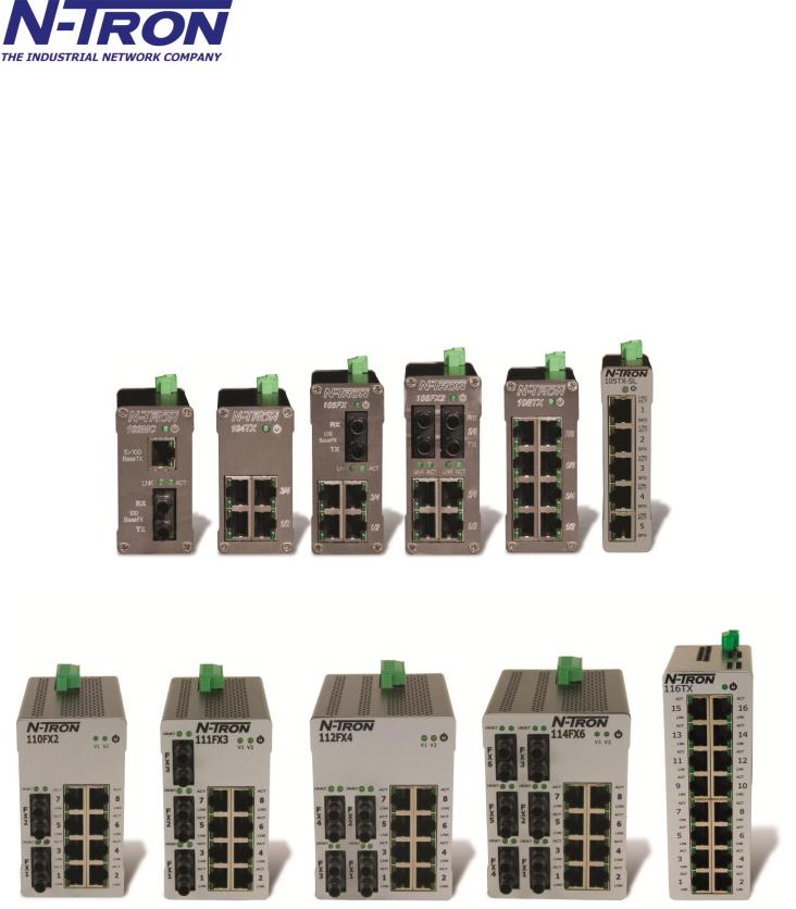
100 Series Industrial Ethernet Switches
The 100 Series Unmanaged Industrial Ethernet Switches support high speed layer 2 switching between ports. This series of switches are housed in a ruggedized aluminum enclosure, and provide Category-5 compliant 10/100-BaseT connections for high performance network design, and hub/repeater upgrades.
All fiber products utilize the IEEE compliant SC or ST duplex connectors for fiber optic communications. All 10/100Base-TX ports utilize the RJ45 shielded connectors.
The 102MC/MCE is a two-port unmanaged media converter that converts 10/100BaseTX copper to 100BaseFX full duplex fiber.
The 104TX, 105TX and 108TX are affordable and share a small footprint. Each switch is capable of auto negotiating 10/100 Mb and half/full duplex communications. The five-port 105TX-SL offers the same functionality and is distinguished by its ultra-slim enclosure.
The 105FX/FXE has 4 ports similar to the 104TX, plus additional multimode fiber optic up-link port(s), capable of 2 Kilometers of 100 Mb communications for the FX models, and up to 80 Kilometers for the FXE models without the use of repeaters.
The 106FX2/FXE2 has 4 10/100BaseTX RJ-45 auto sensing ports and 2 100BaseFX ports with ST or SC connectors, capable of 2 Kilometers of 100 Mb communications for the FX models, and up to 80 Kilometers for the FXE models without the use of repeaters.
The 110FX2/FXE2 has 8 10/100BaseTX RJ-45 auto sensing ports and 2 100BaseFX ports with ST or SC connectors, capable of 2 Kilometers of 100 Mb communications for the FX models, and up to 80 Kilometers for the FXE models without the use of repeaters.
The 111FX3/FXE3 has 8 10/100BaseTX RJ-45 auto sensing ports and 3 100BaseFX ports with ST or SC connectors, capable of 2 Kilometers of 100 Mb communications for the FX models, and up to 80 Kilometers for the FXE models without the use of repeaters.
The 112FX4/FXE4 has 8 10/100BaseTX RJ-45 auto sensing ports and 4 100BaseFX ports with ST or SC connectors, capable of 2 Kilometers of 100 Mb communications for the FX models, and up to 80 Kilometers for the FXE models without the use of repeaters.
The 114FX6/FXE6 has 8 10/100BaseTX RJ-45 auto sensing ports and 6 100BaseFX ports with ST or SC connectors, capable of 2 Kilometers of 100 Mb communications for the FX models, and up to 80 Kilometers for the FXE models without the use of repeaters.
The 116TX has 16 10/100BaseTX RJ-45 auto sensing. Each port is capable of auto negotiating 10/100 Mb and half/full duplex communications.
Key Features
Full IEEE 802.3 & 100Base-FX Compliance
Extended Environmental Specifications
Support for Full/Half Duplex Operation
LED Link/Activity Status Indication
Autonegotiation, Autosensing Speed, Duplex, and Flow Control
Up to 3.2 Gb/s Maximum Throughput
Industry Standard 35mm DIN Rail Mounted Enclosure
(Revised 2011-04-15) |
6 |

PACKAGE CONTENTS
Please make sure the package contains the following items:
1.100 Series Media Converter or Ethernet Switch
2.Instruction Sheet
Contact your carrier if any items are damaged.
UNPACKING
Remove all the equipment from the packaging, and store the packaging in a safe place. File any damage claims with the carrier.
CLEANING
Clean only with a damp cloth.
INSTALLATION
Read the following warning before beginning the installation:
WARNING
Never install or work on electrical equipment or cabling during periods of lightning activity. Never connect or disconnect power when hazardous gasses are present.
LASER SAFETY (MCE and FXE models only -40 and -80)
CAUTION: CLASS 1 LASER PRODUCT. Do not stare into the laser!
(Revised 2011-04-15) |
7 |
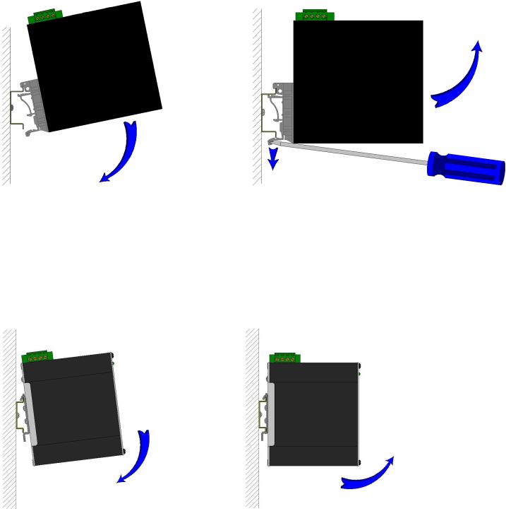
DIN-Rail Mounting
Install the unit in a standard DIN rail. Recess the unit to allow at least 2” of horizontal clearance for CAT5e cable bend radius.
To install the plastic clip units to 35mm industrial DIN rail, place the top edge of the included mounting bracket on the back of the unit against the DIN rail at a 15° angle as shown. Rotate the bottom of the unit to the back (away from you) until it snaps into place.
To remove the plastic clip units from the 35mm industrial DIN rail, place a flat head screwdriver into the release clip found at the bottom of the unit, and apply downward force on the clip until it disengages from the bottom of the unit from the DIN rail. Rotate the bottom of the unit towards you and up at an approximate 15° upward angle to completely remove the unit.
To install the metal clip units to 35mm industrial DIN rail, place the top edge of the included mounting bracket on the back of the unit against the DIN rail at a 15° angle as shown. Rotate the bottom of the unit to the back (away from you) until it snaps into place.
To remove the metal clip units from the 35mm industrial DIN rail, pull forward on the unit until it disengages from the bottom of the DIN rail. Rotate the bottom of the unit towards you and up at an approximate 15° upward angle to completely remove the unit.
(Revised 2011-04-15) |
8 |
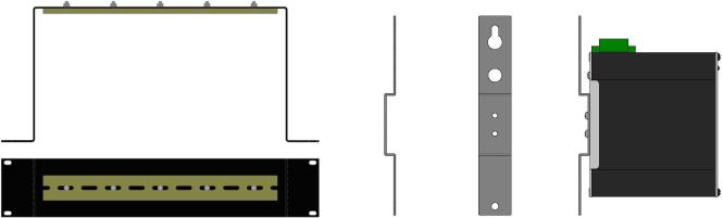
URMK |
1000-PM |
Most N-Tron™ products are designed to be mounted on industry standard 35mm DIN rail. However, DIN rail mounting may not be suitable for all applications. Our Universal Rack Mount Kit (P/N: URMK) may be used to mount the 100 Series enclosures to standard 19" racks, and our Panel Mount Assembly (P/N: 1000-PM) may be used to mount the metal clip versions of the 100 Series enclosures to a panel or any other flat surface. NOTE: the 1000-PM will only work with the factory installed –MDR metal clip options and it is not acceptable for the 116TX units.
(Revised 2011-04-15) |
9 |

FRONT PANEL
From Top to Bottom: |
|
SPD |
Speed LED |
LNK/ACT |
Link/Activity LED |
RJ45 Ports |
Auto sensing 10/100BaseT Connection |
|
Green LED lights when Power is connected |
NOTE: The top LED indicates Link/Activity (LNK/ACT), and the lower LED indicates Speed (SPD) status.
(Revised 2011-03-14) |
10 |
LED’s: The table below describes the operating modes:
LED |
Color |
Description |
|
ON |
Power is Applied. |
|
|
|
|
OFF |
Power is OFF. |
|
|
|
|
ON |
Link established, no Activity on cable. |
|
|
|
LNK/ACT |
BLINKING |
Link established, Activity on cable |
|
|
|
|
|
|
|
OFF |
No link activity on cable. |
|
|
|
|
ON |
LINK is 100Mbps. |
SPD |
|
|
|
OFF |
Link is 10Mbs. |
|
|
|
APPLYING POWER
• 102MC, 104TX, 105TX, 105FX, 106FX2, 108TX, and 116TX Power Connector (Top View)
(Revised 2011-03-14) |
11 |
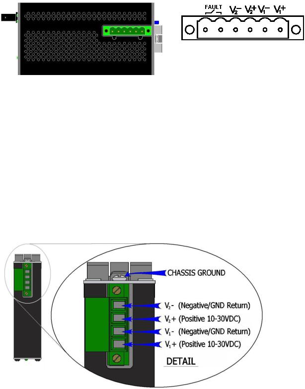
•110FX2, 111FX3, 112FX4, and 114FX6 Power Connector (Top View) (must be powered by Class 2 source only)
Unscrew & Remove the DC Voltage Input Plug from the top header. Install the DC Power Cables into the Plug (observing polarity on unit). Plug the Voltage Input Plug back into the top header. Tightening torque for the terminal block power plug is 0.22 Nm/0.162 Pound Foot.
All LED’s will flash ON Momentarily. Verify the Power LED stays ON (GREEN).
Note: Either V1 or V2 can be connected to power for minimal operation. For redundant power operation, V1 and V2 plugs must be connected to separate DC Voltage sources. Use wire sizes of 16-28 gauge. The power cord should be limited to less than 10 meters in order to ensure optimum performance.
Recommended 24V DC Power Supplies, similar to:
100-240VAC: N-Tron NTPS-24-1.3, DC 24V/1.3
• 105TX-SL (Top View)
Unscrew & Remove the DC Voltage Input Plug from the top header. Install the DC Power Cables into the Plug (observing polarity on unit). Plug the Voltage Input Plug back into the top header. Tightening torque for the terminal block power plug is 0.5 Nm/0.368 Pound Foot.
(Revised 2011-03-14) |
12 |
 Loading...