

NTE NTE5457, NTE5455, NTE5452, NTE5458, NTE5454 Datasheet
...
NTE5452 thru NTE5458
Silicon Controlled Rectifier (SCR)
4 Amp Sensitive Gate
Description:
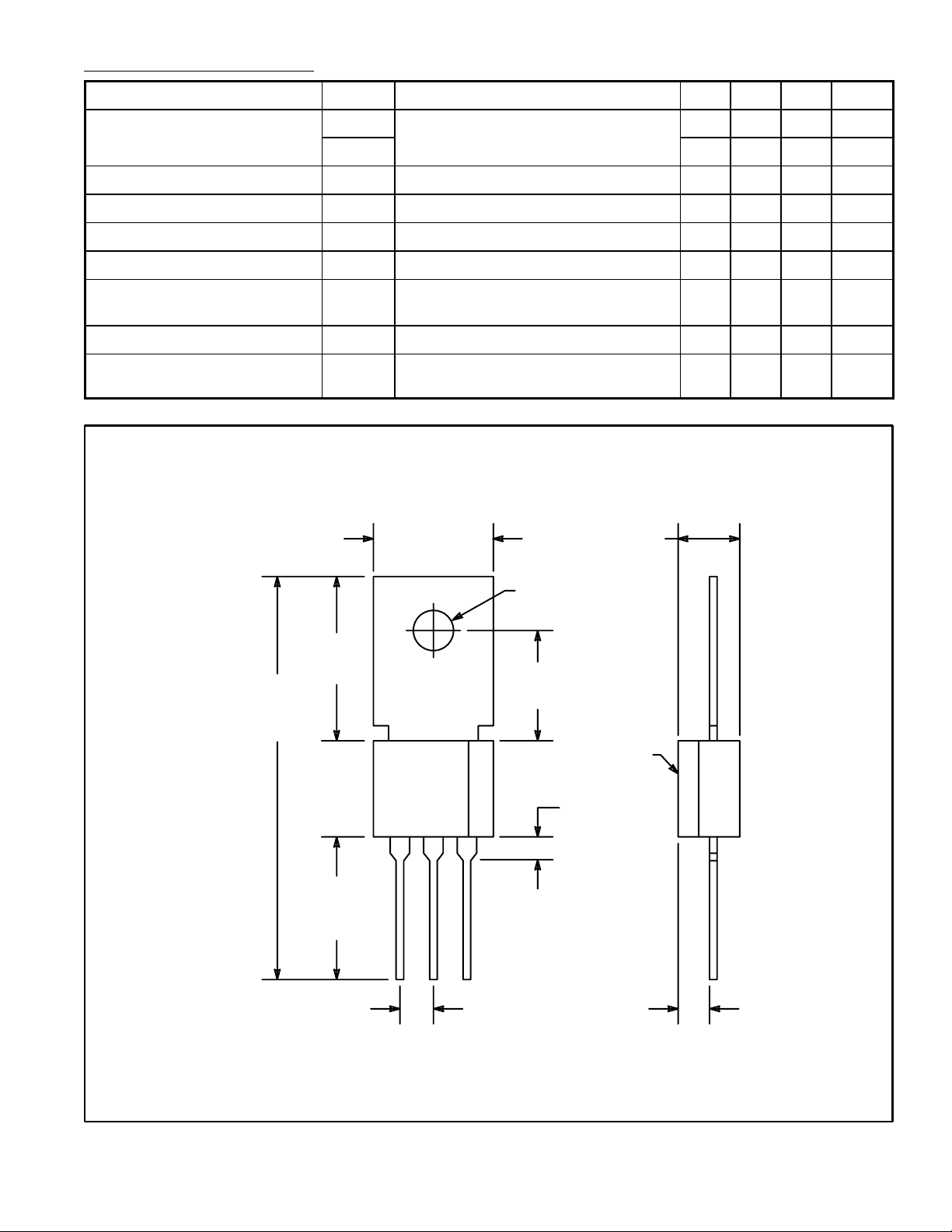
The NTE5452 through NTE5458 are sensitive gate 4 Amp SCR’s in a TO202 type package designed
to be driven directly with IC and MOS devices. These reverse–blocking triode thyristors may be
switched from off–state to conduction by a current pulse applied to the gate terminal. They are designed for control applications in lighting, heating, cooling, and static switching relays.
Absolute Maximum Ratings:
Repetitive Peak Reverse Voltage (TC = +100°C), V
NTE5452 30V. . . . . . . . . . . . . . . . . . . . . . . . . . . . . . . . . . . . . . . . . . . . . . . . . . . . . . . . . . . . . . . . . . . .
NTE5453 50V. . . . . . . . . . . . . . . . . . . . . . . . . . . . . . . . . . . . . . . . . . . . . . . . . . . . . . . . . . . . . . . . . . . .
NTE5454 100V. . . . . . . . . . . . . . . . . . . . . . . . . . . . . . . . . . . . . . . . . . . . . . . . . . . . . . . . . . . . . . . . . . .
NTE5455 200V. . . . . . . . . . . . . . . . . . . . . . . . . . . . . . . . . . . . . . . . . . . . . . . . . . . . . . . . . . . . . . . . . . .
NTE5456 300V. . . . . . . . . . . . . . . . . . . . . . . . . . . . . . . . . . . . . . . . . . . . . . . . . . . . . . . . . . . . . . . . . . .
NTE5457 400V. . . . . . . . . . . . . . . . . . . . . . . . . . . . . . . . . . . . . . . . . . . . . . . . . . . . . . . . . . . . . . . . . . .
NTE5458 600V. . . . . . . . . . . . . . . . . . . . . . . . . . . . . . . . . . . . . . . . . . . . . . . . . . . . . . . . . . . . . . . . . . .
Repetitive Peak Off–State Voltage (T
= +100°C), V
C
NTE5452 30V. . . . . . . . . . . . . . . . . . . . . . . . . . . . . . . . . . . . . . . . . . . . . . . . . . . . . . . . . . . . . . . . . . . .
NTE5453 50V. . . . . . . . . . . . . . . . . . . . . . . . . . . . . . . . . . . . . . . . . . . . . . . . . . . . . . . . . . . . . . . . . . . .
NTE5454 100V. . . . . . . . . . . . . . . . . . . . . . . . . . . . . . . . . . . . . . . . . . . . . . . . . . . . . . . . . . . . . . . . . . .
NTE5455 200V. . . . . . . . . . . . . . . . . . . . . . . . . . . . . . . . . . . . . . . . . . . . . . . . . . . . . . . . . . . . . . . . . . .
NTE5456 300V. . . . . . . . . . . . . . . . . . . . . . . . . . . . . . . . . . . . . . . . . . . . . . . . . . . . . . . . . . . . . . . . . . .
NTE5457 400V. . . . . . . . . . . . . . . . . . . . . . . . . . . . . . . . . . . . . . . . . . . . . . . . . . . . . . . . . . . . . . . . . . .
NTE5458 600V. . . . . . . . . . . . . . . . . . . . . . . . . . . . . . . . . . . . . . . . . . . . . . . . . . . . . . . . . . . . . . . . . . .
RMS On–State Current, I
T(RMS)
Peak Surge (Non–Repetitive) On–State Current (One Cycle at 50 or 60Hz), I
Peak Gate–Trigger Current (3µs Max), I
Peak Gate–Power Dissipation (I
GT
Average Gate Power Dissipation, P
Operating Temperature Range, T
Storage Temperature Range, T
opr
stg
≤ I
G(AV)
GTM
for 3µs Max), P
GTM
Typical Thermal Resistance, Junction–to–Case, R
RRM
DRXM
thJC
GM
TSM
4A. . . . . . . . . . . . . . . . . . . . . . . . . . . . . . . . . . . . . . . . . . . . . . . . . . . . . . .
20A. . . . . . . . . . .
1A. . . . . . . . . . . . . . . . . . . . . . . . . . . . . . . . . . . . . . . . . . . .
20W. . . . . . . . . . . . . . . . . . . . . . . . . . .
200mW. . . . . . . . . . . . . . . . . . . . . . . . . . . . . . . . . . . . . . . . . .
–40° to +100°C. . . . . . . . . . . . . . . . . . . . . . . . . . . . . . . . . . . . . . . .
–40° to +150°C. . . . . . . . . . . . . . . . . . . . . . . . . . . . . . . . . . . . . . . . . .
+5°C/W. . . . . . . . . . . . . . . . . . . . . . . . . . . . . .
Electrical Characteristics:
Parameter Symbol Test Conditions Min Typ Max Unit
Peak Off–State Current
I
I
DRXM
Maximum On–State Voltage V
DC Holding Current I
HOLD
DC Gate–Trigger Current I
DC Gate–Trigger Voltage V
Total Gate Controlled
RRM
TM
GT
GT
t
gt
V
= Max, V
RRM
TC = +100°C, R
DRXM
G–K
= Max,
= 1kΩ
TC = +25°C, IT = 4A (Peak) – – 2.2 V
TC = +25°C – – 3 mA
VD = 6VDC, RL = 100Ω, TC = +25°C – 50 200 µA
VD = 6VDC, RL = 100Ω, TC = +25°C – – 0.8 V
TC = +25°C – 1.2 – µs
– – 100 µA
– – 100 µA
Turn–On Time
I2t for Fusing Reference I2t > 1.5msoc – – 0.5 A2sec
Critical rate of Applied
Forward Voltage
dv/dt
(critical)
R
= 1kΩ, TC = +100°C – 8 – V/µs
G–K
.380 (9.56) .180 (4.57)
A
.500
(12.7)
1.200
(30.48)
Ref
.300
(7.62)
.380
(9.65)
Min
KAG
.100 (2.54) .100 (2.54)
.132 (3.35) Dia
.325
(9.52)
.070 (1.78) x 45°
Chamf
.050 (1.27)
 Loading...