

NTE NTE5404, NTE5403, NTE5401, NTE5400, NTE5406 Datasheet
...
NTE5400 thru NTE5406
Silicon Controlled Rectifier (SCR)
0.8 Amp Sensitive Gate
Description:
The NTE5400 through NTE5406 sensitive gate SCR semiconductors are halfwave unidirectional
gate controlled rectifiers (SCR–thyristor) rated at 0.8 amps RMS maximum on–state current, with
rated voltages up to 600 volts.
These devices feature 200 microamp gate sensitivity, 5 millamp holding current and 8 amp surge capabilities.
Available in a TO–92 plastic package, these devices feature excellent environmental stress and temperature cycling characteristics and, coupled with their small size and electrical performance, lend
themselves to various types of control functions encountered with sensors, motors, lamps, relays,
counters, triggers, etc.
Absolute Maximum Ratings:
Repetitive Peak Reverse Voltage (TC = +100°C), V
NTE5400 30V. . . . . . . . . . . . . . . . . . . . . . . . . . . . . . . . . . . . . . . . . . . . . . . . . . . . . . . . . . . . . . . . . . . .
NTE5401 60V. . . . . . . . . . . . . . . . . . . . . . . . . . . . . . . . . . . . . . . . . . . . . . . . . . . . . . . . . . . . . . . . . . . .
NTE5402 100V. . . . . . . . . . . . . . . . . . . . . . . . . . . . . . . . . . . . . . . . . . . . . . . . . . . . . . . . . . . . . . . . . . .
NTE5403 150V. . . . . . . . . . . . . . . . . . . . . . . . . . . . . . . . . . . . . . . . . . . . . . . . . . . . . . . . . . . . . . . . . . .
NTE5404 200V. . . . . . . . . . . . . . . . . . . . . . . . . . . . . . . . . . . . . . . . . . . . . . . . . . . . . . . . . . . . . . . . . . .
NTE5405 400V. . . . . . . . . . . . . . . . . . . . . . . . . . . . . . . . . . . . . . . . . . . . . . . . . . . . . . . . . . . . . . . . . . .
NTE5406 600V. . . . . . . . . . . . . . . . . . . . . . . . . . . . . . . . . . . . . . . . . . . . . . . . . . . . . . . . . . . . . . . . . . .
Repetitive Peak Off–State Voltage (TC = +100°C), V
NTE5400 30V. . . . . . . . . . . . . . . . . . . . . . . . . . . . . . . . . . . . . . . . . . . . . . . . . . . . . . . . . . . . . . . . . . . .
NTE5401 60V. . . . . . . . . . . . . . . . . . . . . . . . . . . . . . . . . . . . . . . . . . . . . . . . . . . . . . . . . . . . . . . . . . . .
NTE5402 100V. . . . . . . . . . . . . . . . . . . . . . . . . . . . . . . . . . . . . . . . . . . . . . . . . . . . . . . . . . . . . . . . . . .
NTE5403 150V. . . . . . . . . . . . . . . . . . . . . . . . . . . . . . . . . . . . . . . . . . . . . . . . . . . . . . . . . . . . . . . . . . .
NTE5404 200V. . . . . . . . . . . . . . . . . . . . . . . . . . . . . . . . . . . . . . . . . . . . . . . . . . . . . . . . . . . . . . . . . . .
NTE5405 400V. . . . . . . . . . . . . . . . . . . . . . . . . . . . . . . . . . . . . . . . . . . . . . . . . . . . . . . . . . . . . . . . . . .
NTE5406 600V. . . . . . . . . . . . . . . . . . . . . . . . . . . . . . . . . . . . . . . . . . . . . . . . . . . . . . . . . . . . . . . . . . .
RMS On–State Current, I
T(RMS)
Peak Surge (Non–Repetitive) On–State Current (One Cycle at 50 or 60Hz), I
Peak Gate–Trigger Current (3µs Max), I
Peak Gate–Power Dissipation (IGT ≤ I
Average Gate Power Dissipation, P
Operating Temperature Range, T
Storage Temperature Range, T
opr
stg
GTM
G(AV)
GTM
for 3µs Max), P
Typical Thermal Resistance, Junction–to–Case, R
Typical Thermal Resistance, Junction–to–Ambient, R
RRM
DRXM
thJC
thJA
GM
TSM
0.8A. . . . . . . . . . . . . . . . . . . . . . . . . . . . . . . . . . . . . . . . . . . . . . . . . . . . .
8A. . . . . . . . . . . .
500mA. . . . . . . . . . . . . . . . . . . . . . . . . . . . . . . . . . . . . . . .
20W. . . . . . . . . . . . . . . . . . . . . . . . . . .
200mW. . . . . . . . . . . . . . . . . . . . . . . . . . . . . . . . . . . . . . . . . . .
–40° to +100°C. . . . . . . . . . . . . . . . . . . . . . . . . . . . . . . . . . . . . . . .
–40° to +150°C. . . . . . . . . . . . . . . . . . . . . . . . . . . . . . . . . . . . . . . . . .
+5°C/W. . . . . . . . . . . . . . . . . . . . . . . . . . . . . .
+200°C/W. . . . . . . . . . . . . . . . . . . . . . . . . .
Electrical Characteristics:
Parameter Symbol Test Conditions Min Typ Max Unit
Peak Off–State Current
I
I
DRXM
Maximum On–State Voltage V
DC Holding Current I
HOLD
DC Gate–Trigger Current I
DC Gate–Trigger Voltage V
RRM
TM
GT
GT
V
= Max, V
RRM
TC = +100°C, R
DRXM
G–K
= Max,
= 1kΩ
TC = +25°C, IT = 1.2A (Peak) – – 1.7 V
TC = +25°C – – 5 mA
VD = 6VDC, RL = 100Ω, TC = +25°C – 50 200 µA
VD = 6VDC, RL = 100Ω, TC = +25°C – – 0.8 V
– – 50 µA
– – 50 µA
I2t for Fusing Reference I2t > 1.5msoc – – 0.15 A2sec
Critical Rate of Applied
Forward Voltage
dv/dt
(critical)
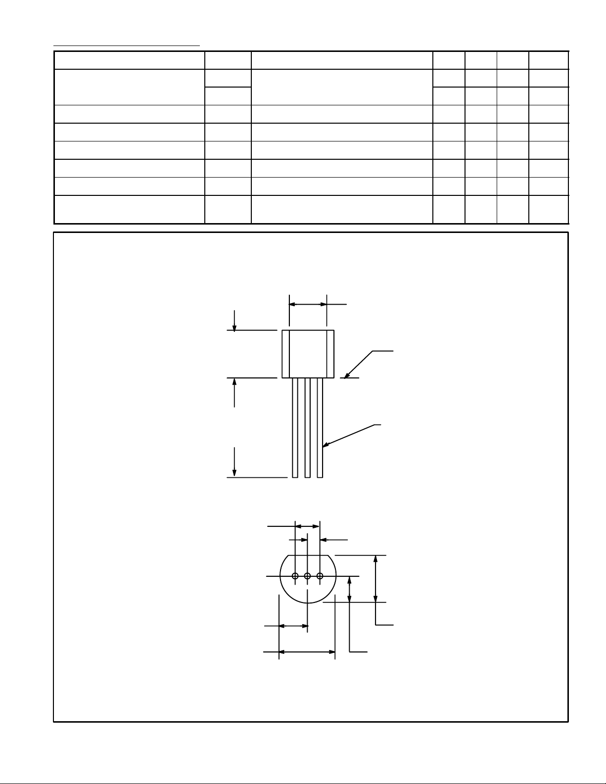
.210
(5.33)
Max
TC = +100°C – 5 – V/µs
.135 (3.45) Min
Seating
Plane
.500
(12.7)
Min
.100 (2.54)
.105 (2.67) Max
.205 (5.2) Max
.021 (.445) Dia Max
KG A
.050 (1.27)
.165 (4.2) Max
.105 (2.67) Max
 Loading...