

NSC DS8673N Datasheet
DS8673/DS8674 Low Power VHF/UHF Prescalers
General Description
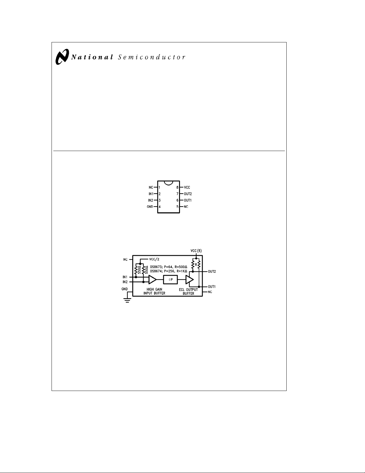
The DS8673 and DS8674 products are low power prescalers which divide by 64 and 256 respectively. The devices
are used in frequency synthesis applications such as TV/
CATV, cellular phone, and instrumentation to divide a very
high frequency down to a frequency usable by low power
MOS PLL’s.
The devices have differential buffered inputs and complementary ECL outputs. The inputs provide high input sensitivity and good isolation. The DS8673 is pin compatible with
Plessey’s SP4531, SP4632, and Motorola’s MC12073 prod-
Block and Connection Diagrams
Dual-In-Line Package
ucts. The DS8674 is pin compatible with Plessey’s SP4653
and Motorola’s MC12074 products.
Features
Y
1.0 GHz operating frequency
Y
25 mA typical supply current
Y
20 mV rms input sensitivity
Y
0.8V complementary ECL outputs
Y
Low output radiation
DS8673/DS8674 Low Power VHF/UHF Prescalers
April 1988
Top View
TL/F/9340– 1
Order Number DS8673N or DS8674N
See NS Package Number N08E
TL/F/9340– 2
C
1995 National Semiconductor Corporation RRD-B30M105/Printed in U. S. A.
TL/F/9340
Absolute Maximum Ratings (Note 1)
If Military/Aerospace specified devices are required,
please contact the National Semiconductor Sales
Office/Distributors for availability and specifications.
Supply Voltage 7V
Input Voltage 7V
Output Voltage V
Operating Free Air Temperature Rangeb40§Ctoa85§C
Storage Temperature Range
ESD rating is to be determined.
b
a
0.5V
CC
65§Ctoa150§C
Recommended Operating Conditions
Symbol Parameter Conditions Min Typ Max Units
V
CC
F
IN
V
IN
Power Supply Voltage Range 4.5 5.5 V
Input Frequency Range VINMin 80 1,000 MHz
Input Sensitivity into 50X 80 MHz 20 200
300 MHz 20 200
500 MHz 20 200 mV rms
700 MHz 20 200
1 GHz 20 200
DC Electrical Characteristics
Symbol Parameter Conditions Min Typ Max Units
I
CC
V
OUT
Note 1: ‘‘Absolute Maximum Ratings’’ are those values beyond which the safety of the device cannot be guaranteed. Except for ‘‘Operating Temperature Range’’
they are not meant to imply that the devices should be operated at these limits. The table of ‘‘Electrical Characteristics’’ provides conditions for actual device
operation.
Power Supply Current V
Output Voltage Swing Peak-to-Peak
e
5.5V 25 35 mA
CC
(no load)
0.8 1.2 1.6 V
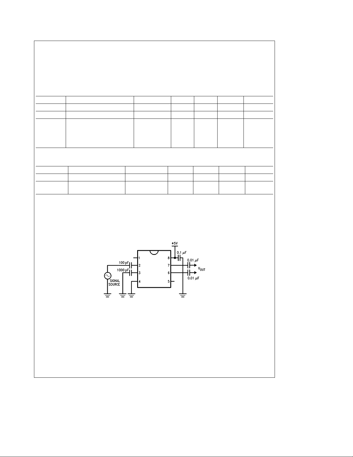
Typical Applications
Typical Wiring Configuration
TL/F/9340– 3
2
 Loading...