

RUA ÁLVARO CHAVES, 155
PORTO ALEGRE – RS – BRAZIL
90220-040
my
myPCProbe
mymy
INSTRUCTION MANUAL
INSTRUCTION MANUAL
INSTRUCTION MANUALINSTRUCTION MANUAL
PCProbe
PCProbePCProbe
TEL: +55 (51) 3323 3600
info@novus.com.br
INTRODUCTION
myPCProbe is either a temperature sensor (TEMP model) or a temperature and humidity sensor (RHT model) that
features an USB interface for communication with your PC. It is the ideal instrument for monitoring and recording lab
data from teaching, research and industry settings. It is supplied with an Windows application that enables the instant
visualization of logged data in display, bar, gauge or chart formats. The application provides history data logging of
myPCProbe readings, offering resources to visualize data graphically and to export them in different formats. The PC
USB port is accessed as a virtual serial port, which enables compliance with SCADA software that support Modbus RTU
serial communication, or any other application that supports ASCII serial communication.
Multiple modules can be installed, one at each USB port, thus making it easier to increase the number of inputs.
myPCLab application can communicate simultaneously with all installed sensors.
This guide brings the installation and module connection instructions. For information on myPCLab use instructions,
refer to the online Help.
SPECIFICATIONS
TEMP Model (temperature)
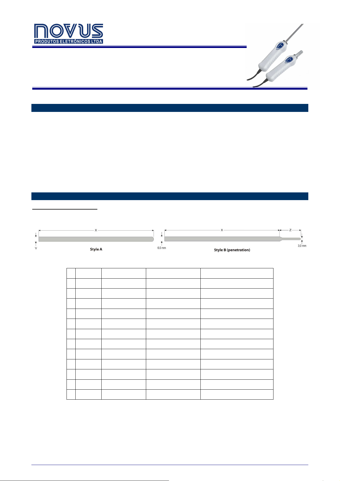
● Sensors: The required sensor model must be defined at purchase. Available models are listed below, with their
respective measurement ranges.
Figure 01 – Available probe styles
Style Dimensions (mm) Sensor Measurement Range
1 A X = 150,0; Y = 3,0 Pt100 -200 to 200 ºC (-328 to 392 ºF)
2 A X = 150,0; Y = 3,0 Mineral thermocouple K -100 to 500 ºC (-148 to 932 ºF)
3 A X = 300,0; Y = 3,0 Pt100 -200 to 200 ºC (-328 to 392 ºF)
4 A X = 300,0; Y = 3,0 Mineral thermocouple K -100 to 500 ºC (-148 to 932 ºF)
5 A X = 300,0; Y = 6,0 Pt100 -200 to 300 ºC (-328 to 572 ºF)
6 A X = 300,0; Y = 6,0 Mineral thermocouple K -100 to 1000 ºC (-148 to 1932 ºF)
7 A X = 500,0; Y = 6,0 Pt100 -200 to 300 ºC (-328 to 572 ºF)
8 A X = 500,0; Y = 6,0 Mineral thermocouple K -100 to 1200 ºC (-148 to 2192 ºF)
9 B X = 120,0; Z = 30,0 Pt100 -200 to 200 ºC (-328 to 392 ºF)
10
11
12
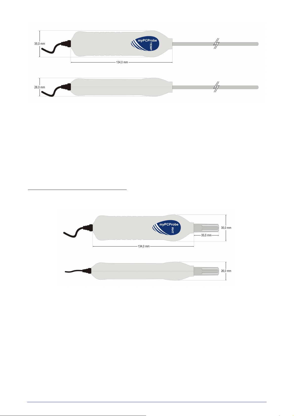
● Dimensions: Refer to Figure 02, Table 01 and Figure 01.
NOVUS PRODUTOS ELETRÔNICOS LTDA www.novus.com.br 1/11
B X = 120,0; Z = 30,0 Mineral thermocouple K -100 to 300 ºC (-148 to 572 ºF)
B X = 75,0; Z = 25,0 Pt100 -200 to 200 ºC (-328 to 392 ºF)
B X = 75,0; Z = 25,0 Mineral thermocouple K -100 to 300 ºC (-148 to 572 ºF)
Table 01 - myPCProbe-TEMP available models, defined at purchase
myPCProbe
Figure 02 – TEMP model dimensions
●
Ambient temperature channel: Internal thermistor.
● Built-in cold junction compensation for thermocouples and wire resistance for Pt100.
● Total accuracy:
Thermocouple K: ± 4.5°C (when maximum resolution is selected);
Pt100: ± 1.5°C (when maximum resolution is selected);
Ambient Temperature Channel: ± 1.5°C (20 minutes after connection to the USB port)
Note: It is possible to reduce (and even cut out) errors if after calibration the calibration points are
transferred to the device using the custom calibration screen (via software).
● A/D resolution: Configurable from 15 to 11 bits.
● Sampling rate: 8 to 128 samples per second, depending on resolution and number of channels enabled.
RHT Model (temperature and relative humidity)
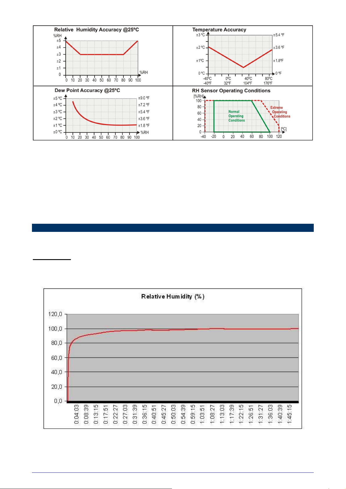
● Maximum measurement range: -20 to 100ºC and 0 to 100% RH (available also as dew point). See Figure 04
“Humidity sensor operating conditions”.
● Dimensions: See Figure 03.
Figure 03 - RHT model dimensions
● Accuracy: See Figure 04.
Note: It is possible to reduce (and even cut out) errors if after calibration the calibration points are
transferred to the device using the custom calibration screen (via software).
NOVUS PRODUTOS ELETRONICOS LTDA www.novusautomation.com 2/11
myPCProbe
Figure 04 – Operating accuracy and conditions of RHT model
● Sampling rate: one sample at every 1 or 3 seconds, depending on the resolution selected.
PC interface: Plug and Play USB (compatible with V1.1 and V2.0), virtual serial port interface, 1.5 m long cable.
Power supply: From the USB bus. Typical current: 30 mA
Supports custom multipoint calibration, which allows for an increase of system accuracy.
Handle operating environment: 0 to 60°C and 0 to 95% RH non-condensing.
Electromagnetic compatibility: EN 50081-2, EN 50082-2.
ABS case.
TESTS
This section shows the step response of some myPCProbe models to humidity (RHT model) and temperature (TEMP
model).
RHT MODEL
The myPCProbe-RHT was taken from an extremely dry environment and placed in an extremely wet environment.
Response time (0 to 90%) = 07 min 45 s
Figure 05 - RHT model humidity step response
NOVUS PRODUTOS ELETRONICOS LTDA www.novusautomation.com 3/11
myPCProbe
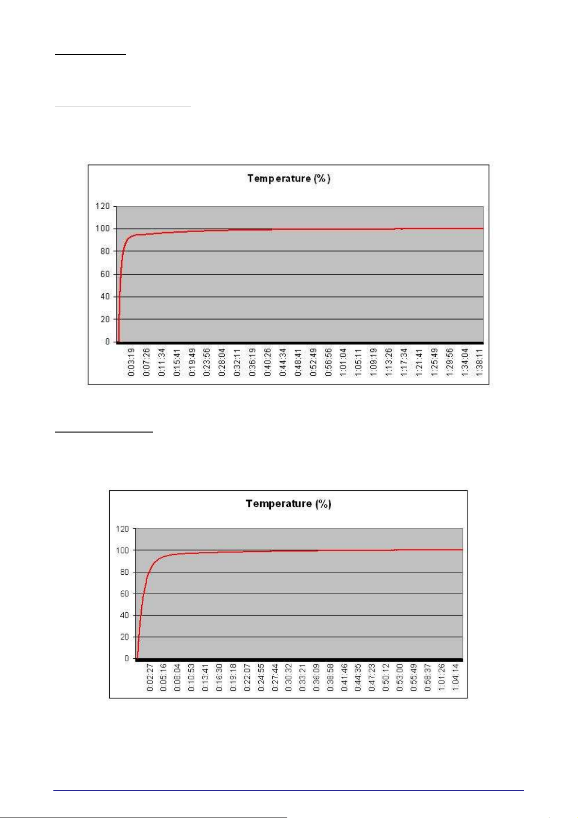
TEMP MODEL
In these tests, a calibration furnace was used to provide the required final temperature. Basal temperature was room
temperature (around 25ºC; 77 ºF).
150 x 3 mm probe, thermocouple K
Features: See model number 2 in Table 01.
Probe inserted 130 mm in the furnace.
Response time (0 to 90%) = 2 min 12 s
Figure 06 – TEMP model temperature step response with 150 x 3 mm, thermocouple K probe
300 x 6 mm probe, Pt100
Features: See probe number 5 in Table 01.
Probe inserted 150 mm in the furnace.
Response time (0 to 90%) = 3 min 46 s
Figure 07 – TEMP model temperature step response with 300 x 6 mm, Pt100 probe
NOVUS PRODUTOS ELETRONICOS LTDA www.novusautomation.com 4/11

300 x 6 mm probe, thermocouple K
Features: See model number 6 in Table 01.
Probe inserted 150 mm in the furnace.
Response time (0 to 90%) = 1 min 21 s
myPCProbe
Figure 08 – TEMP model temperature step response with 300 x 6 mm, thermocouple K probe
500 x 6 mm probe, Pt100
Features: See model number 7 in Table 01.
Probe inserted 150 mm in the furnace.
Response time (0 to 90%) = 3 min 36 s
Figure 09 – TEMP model temperature step response with 500 x 6 mm, Pt100 probe
NOVUS PRODUTOS ELETRONICOS LTDA www.novusautomation.com 5/11

100 mm penetration probe, Pt100
Features: See model number 12 in Table 01.
Probe inserted 80 mm in the furnace.
Response time (0 to 90%) = 2 min 29 s
myPCProbe
Figure 10 – TEMP model temperature step response with thermocouple K 100 mm penetration probe
NOVUS PRODUTOS ELETRONICOS LTDA www.novusautomation.com 6/11

myPCProbe
USB DRIVER INSTALLATION
The following installation steps may be slightly different depending on your PC configuration and Windows version.
Follow the Wizard instructions and use the following steps and figures to select the correct installation options.
1. Insert the myPCProbe CD in the CD-ROM drive.
2. Connect the module to a PC USB port. Windows® will detect the new hardware and after a few seconds the new
hardware wizard will start.
3. The Found New Hardware Wizard will show-up and ask if you want to connect to Windows Update to get the driver.
Select the “No, not this time” and select “Next”.
4. Select “Install from a list or specific location (advanced)” and select “Next”.
5. Select “Search for the best driver in these locations” and check option “Search removable media”. Select “Next”. If
the installation files are not in a CD, select option “Include this location in the search” and type the path for the
required files.
6. If a warning message regarding Windows® XP compatibility appears, select “Continue Anyway”.
7. The myPCProbe driver files will be copied to your computer and, when concluded, a window will show up informing
that the wizard has finished installing the software. Select “Finish”.
8. It is possible that the previous steps repeat a second time for the completion of installation.
After driver installation, proceed to the next chapter to install the myPCLab software that provides configuration,
visualization, recording and data export.
In future connection of myPCProbe modules, it is possible that Windows® prompt again for the USB driver installation.
In this case, the same wizard will be presented. Follow the above steps, but select option “Install the software
automatically (recommended)”, since the driver files are already installed.
The following figures are examples of Windows XP® New Hardware Wizard. For Windows 2000® they look different, but
the information is the same.
NOVUS PRODUTOS ELETRONICOS LTDA www.novusautomation.com 7/11

myPCProbe
SOFTWARE INSTALLATION
The myPCLab software is a Windows program intended to:
• Configuration of myPCProbe and myPCLab modules.
• Plot and record data, show gauges, bargraphs and digital
readouts with data from multiple modules.
• Export acquired data in multiple file formats (xls, pdf, rtf, xml, html,
dbf, txt, csv).
To install, execute file myPCLabSetup.exe from the installation CD, and
follow the instructions to proceed with installation.
The myPCLab software has a complete help system, with all the
necessary information for its use. Start the software and press F1 or
select the Help menu to show the help content.
The myPCLab software can simultaneously communicate with multiple modules, making easy to expand the number of
inputs of a measurement system.
SERIAL PORT (COM PORT) ASSIGNMENT
A few seconds after connection of a myPCProbe, Windows operating system assigns a COM port number for
communication. The assigned COM port number will not change in future connections to the same USB port. Users can
easily identify and modify the assigned COM port in:
Control Panel / System / Hardware / Device Manager / Ports (COM & LPT)
Select the desired myPCProbe device, click with the right mouse button and select “Properties”. Select “Port Settings”
and click on the “Advanced...” button. In “COM Port Number” list, select the serial port to be assigned. Some serial port
can be marked as “in use”. Only select one of these ports if you are sure it is not being used by any other peripheral in
your computer.
In some cases, serial port can be marked as “in use” even when the associated device is not in the computer. In this
case, it is safe to assign this port to myPCProbe.
The following figures illustrate the most important steps for this procedure.
NOVUS PRODUTOS ELETRONICOS LTDA www.novusautomation.com 8/11

myPCProbe
NOVUS PRODUTOS ELETRONICOS LTDA www.novusautomation.com 9/11

myPCProbe
APPENDIX 1 – SERIAL COMMUNICATION PROTOCOLS
Each myPCProbe module installed in a PC is accessible as a distinct serial COM port. A module can communicate in
one of two protocols: ASCII (delimited text) or Modbus RTU. Any program with serial communication capability using one
of these protocols may be used to gather measurement data from the modules.
The used communication protocol depends on the “auto-send” module configuration. See the software help for
information on how the change the “auto-send” configuration.
• Auto-send disabled: Communicates using Modbus RTU protocol. The module is a slave that responds to read
requests issued by a Modbus master (for example a SCADA software).
• Auto-send enabled: Communicates using ASCII (delimited text) protocol. The module transmits continuously the
values measured in its channels, in text format.
The module can only be configured using the myPCLab software.
The serial COM port assigned to a device will only be available a few seconds after connection of the
myPCProbe module to a USB port, since Windows operating systems needs to load the appropriate
drivers. To check the COM port assigned to each module, use the myPCLab software or go to the
Windows Control Panel in:
Control Panel/System/Hardware/Device Manager/Ports (COM & LPT)
MODBUS RTU (AUTO-SEND MODE DISABLED)
myPCProbe is a Modbus RTU slave that can answer to “Read Holding Register” requisitions, Modbus command number
3. The module doesn’t have a specific Modbus address, since it’s the only device in its serial port. It will answer to read
request to any valid slave address.
When configuring the serial communication parameters of the Modbus master, set the COM port number assigned to the
device. The USB port ignores all other serial communication parameters.
• Communication Port: Select the COM port number assigned to the myPCProbe.
• Baud rate: any
• Number of data bits: any
• Stop bits: any
• Parity: any
The following table shows the Modbus registers available for reading. Three different address formats are presented.
Use the address format according to your Modbus master.
Modbus Address (in 3 different formats)
Protocol, 0 based Protocol, 1 based PLC Content
4 5 40005 Channel 1 value
5 6 40006 Channel 2 value (RHT model)
6 7 40007 Ambient temperature value (TEMP model)
Holding Registers Table (reference 4X)
• Channel 1 and 2 values
Current value of the input channel, in engineering units. For values with decimal places, the decimal point
separator will be omitted. Example: A channel with value 13.9 will be read as 139.
Measured values above or below its specified limits will be replaced by the corresponding overflow or underflow
values, according to the module configuration.
A disabled channel will return 0 (zero) as its measured value.
• Ambient Temperature Value
Current measurement from the internal ambient temperature sensor, in degrees Celsius or Fahrenheit, according
to module configuration. The decimal point separator is omitted. Example: 23.8°C is read as 238.
Never send a Modbus write command to a module. Configuration or calibration registers may get corrupted
and the module may get unusable.
ASCII – DELIMITED TEXT (AUTO-SEND MODE ENABLED)
When configured to the auto-send mode, the myPCProbe module transmits to its USB port a line of text containing the
current value of all measurement channels. A new line of text is transmitted after each measurement interval, according
to the module configuration.
Any software with serial communication capabilities can receive these data. When configuring the serial communication
parameters of the software, set the COM port number assigned to the device. The USB port ignores all other serial
communication parameters.
• Communication Port: Select the COM port number assigned to the myPCProbe.
• Baud rate: any
• Number of data bits: any
• Stop bits: any
• Parity: any
NOVUS PRODUTOS ELETRONICOS LTDA www.novusautomation.com 10/11

myPCProbe
The simplest way to receive and display data is using a simple communication terminal software, like Windows®
HyperTerminal. This software display on the screen all data received in the specified COM port. Other softwares like
Matlab, Simulink, HPVee, Testpoint, can also be configured to receive and parse measured data.
When operating in the auto-send mode, myPCProbe doesn’t expect to receive any information from the USB port. It
transmits data continuously, with no control from the receiver. If, during a transmission, the module receives a Modbus
RTU command, it will suspend the auto-send mode for 3 seconds and answer the Modbus request. After 3 seconds the
auto-send mode will resume.
The line of text sent after each measurement interval has the following format:
#AAA;BBB;CCC;DDD;EEE\r\n
Where:
• “#” is the start of line delimiter.
• “;” is the separator of measurement values.
• “
AAA
” is always 0 (zero).
• “
BBB
” is the value of channel 1 (TEMP model) or humidity (RHT model).
• “
CCC
” is the value of temperature (RHT model).
• “
DDD
” is the value of the ambient temperature (TEMP model).
• “
EEE
” is the time in milliseconds since the transmission of the first line.
• “
\r\n
” are ASCII values 13 (Carriage Return) and 10 (Line Feed), end of line delimiters (these
characters are not visible).
Measurements containing values with decimal separators will be transmitted with the character ‘.’ (ASCII 46). Examples:
#0;258.1;-5.7;24.6;16772
#0;74.0;50.3;0;4900
#0;-10.9;0;19.4;338105
NOVUS PRODUTOS ELETRONICOS LTDA www.novusautomation.com 11/11
 Loading...