

Page 1
Controller N480
TEMPE RAT URE CONTROLLER – OPERATION MANUAL – V2.6x
1. ASSEMBLY
The control ler should be inst alled in a panel cut out as speci fied in
item 2. 1. First rem ove the mounting clam p and insert the c ontroller
into the panel c ut out . P lace t he unit into t he panel c ut-out and sl ide
the mounting clamp from the rear to a fi rm grip at the panel.
The internal circ uitry can be f ully remov ed from t he housing without
disconnect ing any wiring. By us ing the thumb just press the tab in
the lower part of the f ront panel, grab firm ly the f ront panel and pull
out the circuitry from the housing.
1.1. ELECTRICAL CONNECTIONS
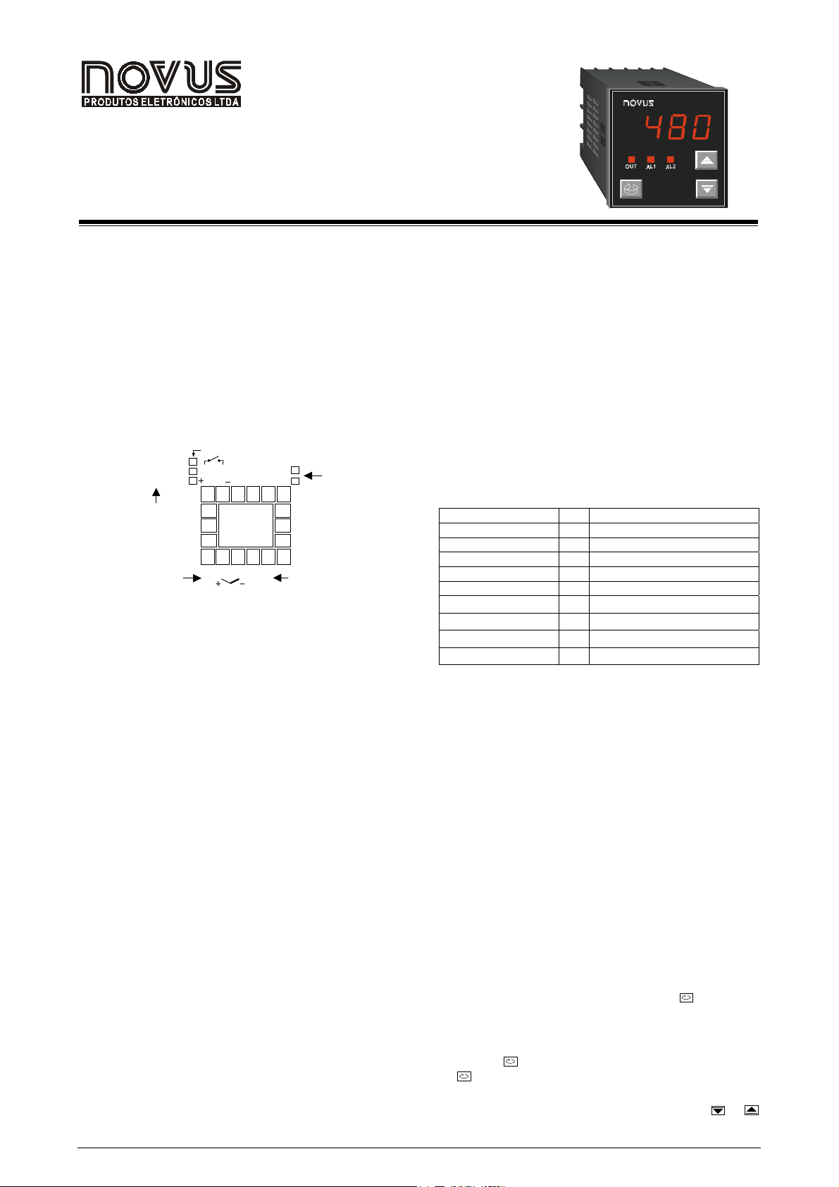
Figure 1 shows the electrical te rm i nal s of the cont rol ler.
RELAY OUTPUT
4-20m A O UTPUT
PULSE OUTPUT
CONTROL
OUTPUT
OR ALARME 1
SENSOR INPUT
2. SPECIFICATIONS
2.1. GENERAL
• Dimensions : 48x48x106mm (1/ 16 DIN).
• Panel cut-out : 45,5x45,5mm
• Weight: 140g (1 relay), 160g (3 relays)
• Power: 85 to 264Vdc/ac, 50/60Hz, 3VA max . Optional: 15
to 30Vdc/ac
• Operation: 0 to 55°C, hum i d i ty 20 to 85%
OUT-A
OUT-B
4-20mA
PULSE
1 2 3 4 5
13
14
15
7 8 9 10 11 12
Figure 1 - Electr ic al connections
AL2
POWER
AC/DC
85-264V
15-30V
6
16
17
18
ALARM 2
POWER
N480
2.5. TEMPERATURE SENSOR INPUT
• Pt100: 3-wire connection. E xcitation current: 170µA
• Thermocouple input i m pedance: 10MΩ
• A/D conv erter resolution: 15000 steps
• Sampling rate: 10 measurements per second
• Accuracy: 0.2% of full scale for Pt100 and 0.25% of full
scale ±1°C for T/C
Thermocouples are connec ted to term inals 8 and 9 with pos itive in
terminal 8.
Pt100 sensors are c onnect ed to t erminal s 7, 8 and 9, as indicated in
figure 1. For full c ompensation of cable resist ance only c ables with
equal wire electri cal resistance should be used.
Table 1 shows the sensor types accepted and their respective
codes. v i a keyboard.
TYPE CODE RANGE
J
K
S
Pt100 (Resolution 0,1°C)
Pt100 (Resolution 1°C)
T
E
N
R
Table 1 - Sensor types, codes and ranges
-50 to 760°C (-58 to 1400°F)
0000
-90 to 1370°C (-130 to 2498°F)
1111
0 to 1760°C (32 to 3200°F)
2222
-199.9 to 530.0°C (-199.9 to 986.0°F)
3333
-200 to 530°C (-328 to 986°F)
4444
5555
-100 to 400 °C (-148 to 752°F)
6666
-30 to 720°C (-22 to 1328°F)
7777
-90 to 1300°C (-130 to 2372°F)
8888
0 to 1760°C (32 to 3200°F)
3. CONFIGURATION AND OPERATION
Prior to firs t operation the c ontroller should be f ully conf igured. The
user mus t set bas ic parameters as temperature t ype (“TYPE
desired c ontrol s et poi nt (“ SP
“SPA2
SPA2”), etc.
SPA2SPA2
SP “), the alarm s s et poi nts (“ SPA1
SPSP
TYPE”), the
TYPETYPE
SPA1” and
SPA1SPA1
2.2. CONTROL OUTPUT
• Relay output: SPST (U type) relay. Maximum current
3A/250Vac.
• Voltage pulse output: 5Vdc/20m A
Both outputs are available in the basic model and the desired
main control output is user selected via keyboard (refer to “
Cntr
Cntr “ prompt ). The remaining output can then be us ed as an
CntrCntr
alarm output.
In case of sensor break or failure an error "Erro
Erro" message is
ErroErro
displayed and t he control output i s turned off.
2.3. ALARM OUTPUTS
• Alarm Output 1: SPST relay 3A/250Vac or 5Vdc/20mA
pulse
• Alarm Output 2: SPST relay 3A/250Vca (optional)
2.4. POWER
Mains power is connected to terminals 5 and 6. Chec k the upper
side of the housing for proper power indicati on.
3.1. PARAMETERS FLOW CHART
The programming parameters are organized in 4 different sets or
levels:
• Operation level
• Alarms and tuning level
• Configuration level
• Calibration level
At power up the c ontroller di splays a prompt at t he Operation Lev el
and remains in this level whil e under normal operation.
The other lev els are only acc ess ed when a c hange of parameters is
necessary (except for Set Point change). To reach these other
parameters the us er must keep the INDEX Key (
) pressed for
about three sec onds. Af ter this time t he control ler will show the first
parameter of the nex t level. By keeping the INDEX key pressed for
another 3 seconds the next level w ill be accessed.
Release the
to go to the next prom pt in the same level.
the
key when t he desi red lev el is reached. Pres s onc e
When a parameter is shown the displ ay will alternate its name and
value. The v alue can then be changed by pressing the
or
key.
Novus Produtos Elet rônic os Lt da. / T el: +55-51-3323-3600 / www.novus.com.br 1/3
Page 2
Controller N480
After the l ast paramet er in one lev el is reac hed the control ler returns
to operation level and the display will indicate the measured
temperature.
The display will also go back to the measured temperature whenever
the display is inacti ve for 20 seconds or m ore.
When a paramet er val ue is c hanged via key board the control ler will
only ac cept the new value af ter the us er presses the INDEX key t o
go to next prompt or if the keyboard is left inac tive for 20 seconds.
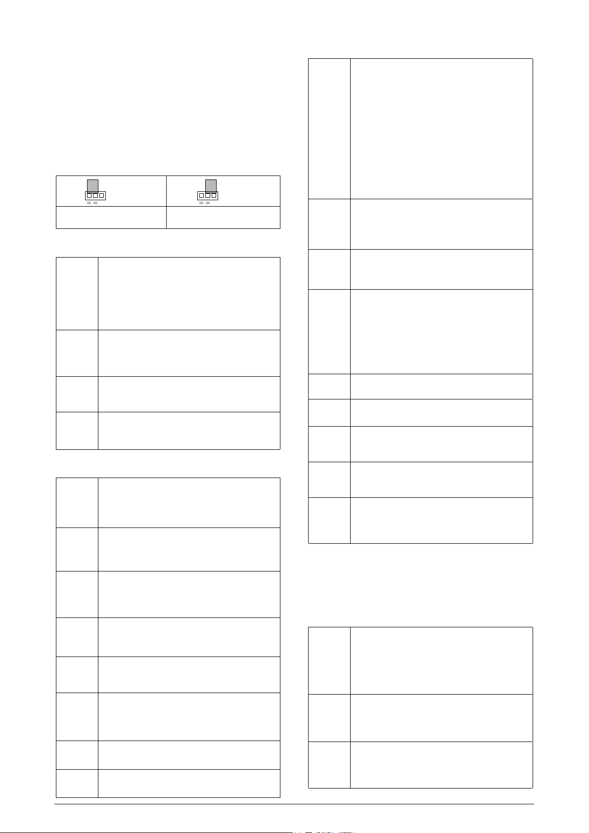
For disabl ing the keyboard, move the internal strap to the posit ion
KEY DISABLE. All parameters will be protected, accept the SP
parameter.
KEY
DISABLE
Figure 2 – St r ap in nor m al operating
position (enabled)
3.2. OPERATION LEVEL
TEMPERATURE
INDICATION
END
SP
Set Point
rAte
rAtE
T Sp
time for soak
Rvn
run
3.3. TUNING AND ALARMS LEVEL
Atvn
Auto tune
Pb
Proportional
band
Ir
integral rate
Dt
derivative
time
(t
Cycle time
KySt
HYSterisis
A1SP
SP Alarm 1
A2SP
SP Alarm 2
TEMPERATURE measured by the sensor.
At power up, the upper di splay shows the process
temperature value. It also shows the messages
described in c hapter 5 of this m anual .
The lower di splay s s hows the s et point v alue which
is the tem perature value desired f or the process.
TEMPE RATURE RATE OF RIS E: The us er defines
the rate of temperature rise from the starting
temperature to t he value set in “ SP
Rate is defi ned i n °C / minute.
TIME FOR SOAK: Time in minutes which the
temperature will remain at the selected “ SP
Refer to item 4.
RUN: At thi s prompt the user sets the c ontrol output
and alarms to ac tive or to inac tive.
0
0 - inactive outputs; 1111 - active outputs;
00
AUTO-TUNE: Activates the auto-tuning of PID
parameters.
0000 - Auto-tune is off;
1111 - Auto-tune is on;
PROPORTI ONAL BAND: percentage of maxim um
input span.
When set ot z ero (0), control acti on is ON/OFF.
INTEGRAL RATE: Integral time constant in
repetitions per minute (Res et). This const ant is not
used when controller is set to ON/OFF action
(Pb=0).
DERIVATIVE TIME: Derivative time constant in
seconds. This c onstant i s not used when controller
is set to ON/OFF action (Pb=0).
CYCLE TIME: Pulse Width Modulation (PWM)
period in seconds. This term is not used when
controller is set to ON/OFF action (Pb=0).
CONTROL HYSTERESIS: Is the hysteresis for
ON/OFF cont rol (set in temperat ure uni ts).
This param eter is only us ed when the controll er is
in ON/OFF mode (Pb=0).
SETPOINT for Alarm 1: Triping point for alarm 1
SETPOINT for Alarm 2: Triping point for alarm 2
Figura 3 – St r ap pos it ion for inhibiting the
KEY
DISABLE
keyboard
SP ”.
SPSP
SP “.
SPSP
3.4. CONFIGURATION LEVEL
INPUT TYPE: Selects the input sensor type t o be
Type
tYPE
Vnit
unit
A(t
ACtion
(ntr
Control
spll
SP Low Limit
spKl
SP High Limit
A1fv
Alarm 1 Function
A2fv
Alarm 2 Function
Aiky
A2ky
Alarm HYsteresis
3.5. CALIBRATION LEVEL
These parameters are used to calibrate the temperature
measurement and s hould only be dealt with by experienc ed and well
equipped personnel.
Inl(
Input Low
Calibration
InK(
Input High
Calibration
(j L
Cold Junction Low
Calibration
connected to the controller. This is the first
parameter to be set.
0
0 - Thermocouple type J;
00
1
1 - Thermocouple type K;
11
2
2 - Thermocouple type S;
22
3
3 - Pt100 with 0,1° resolution;
33
4
4 - Pt100 with 1° resolution;
44
5
5 - Thermocouple type T;
55
6
6 - Thermocouple type E;
66
7
7 - Termopar tipo N;
77
8
8 - Termopar tipo R;
88
TEMPERATURE UNIT: Selects display indication
for degrees Celsius or F arenhei t.
0
0 - degrees Celsius ( °C );
00
1
1 - degrees Farenheit ( °F );
11
CONTROL ACTIO N:
0
0 - reverse action. Generally used for heating.
00
1
1 - direct ac tion. Generally used for cooling.
11
CONTROL OUTP UT :
0
0 - Sets c ontrol output to terminals OUT A.
00
1
1 - Sets c ontrol output to terminals OUT B.
11
As control output is defined to terminals OUT A,
alarm output is automatic al l y set to OUT B.
If cont rol output is defined to OUT B alarm 1 will
then be automati cally set to OUT A.
SET POINT LOW LIMIT: sets t he lower range for
SV
SET POINT HIGH LIMIT
FUNCTION OF ALARM 1: Refer to table 2 for
function des cription and res pective codes to set at
this prompt.
FUNCTION OF ALARM 2: Refer to table 2 for
function des cription and res pective codes to set at
this prompt.
ALARM 1 AND ALARM 2 HYSTERESIS: Defines
the differential range between the PV value at
which t he alarm is turned on and the value at which
it is t urned off (in engineering units).
A T E N T I O N
SENSOR OFFSET CALIBRATION. Sets the
temperature sensor low calibration (offset). The
display shows only the correc ted temperature and
not the offset added. A signal simulat or should be
used to injec t a low value signal to properly adjust
the offset.
INPUT HI GH CALI BRATI ON. S ets the s ensor input
circuit gain or high cal i bration.
A signal simul ator should be used to inject a high
value signal to properl y adjust the offset.
COLD JUNCTION OFFSET CALIBRATION: Sets
the cold junction offset calibration. A good
thermometer or a temperature sim ulator should be
used to properly adj ust this param eter.
: Sets the upper range for SV.
Novus Produtos Elet rônic os Lt da.
Tel.:+55-51-3323-3600
2/3
Page 3
Controller N480
t
4. RAMP TO SOAK FUNCTION CHARACTERISTICS
This func tion m akes the proc ess t emperature ri se gradually from the
starting point (present PV) to the temperature value set in “ SP
(Ramp). The user def ines the rate of ri se in degrees per minute at
the “rAtE
rAtE” prompt.
rAtErAtE
When SP is reac hed the temperat ure is lev eled at this point for 1 to
9999 minutes as programmed at the “ t SP
(zero) at “ t SP
t SP ” defines an i nfinite length soak profile.
t SPt SP
To disable the ramp function Set 0.0 at the “rAtE
disable the s oak f unct ion s et 1 at t he “ t SP
t SP ” prompt. Setting 0
t SPt SP
rAtE” prompt. To
rAtErAtE
t SP ” prompt (thus mak ing
t SPt SP
a 1 minute soak ) and the control output will go off in 1 minute. To
restart c ontrol set 1 at the “ rvn
rvn ” prompt.
rvnrvn
After a power failure the controller will resume ramp to soak
execution at the equivalent previous ramp point. If the proces
temperature is the same as the SP (no temperature drop) the
controller will repeat the soak segment.
SoakTemperature
SP
Ramp
PV
Figure 2 - Ramp to Soak Function
Time
5. PROBLEMS WITH THE CONTROLLER
Connection and configuration errors state for most of the problems in
using the controller. A final revision of parameters will save time and
further losses.
Error messages are dis played to help the user to identify possible
problems.
: Process temperature is below the selected sensor
range.
: Process temperature is above the selected sensor
range
: Controller or sensor error. Ex am pl e:
• Broken thermocouple or Pt100.
• Pt100 badly connec ted, short-c ircuited or hi gh cable
resistance.
5.1. ELECTRONIC SERIAL NUMBER VISUALIZATION
To read the 8-digit serial number go to the Operation Level and
press the
digits. Keep t he
key for 3 s econds. The display will show the first 4
key press ed for 3 seconds and t he display will
show the last 4 digits.
SERIAL NUMBER
LAST 4 DIGITS
FIRST 4 DIGITS
When powering the unit the display will show the software version
for a few sec onds.
6. ALARM FUNCTIONS
Low and high alarms are used to signal minimum and maximum
temperature values as programmed in the “SPA1
prompts.
Differenti al alarms are used to indi cate deviations from the desired
setpoint (SP) t emperature. T hese deviat ions are programmed at the
“SPA1
SPA1” and “ SPA2
SPA1SPA1
SPA2” prompts.
SPA2SPA2
Error alarm shows sensor defect s or not properly connected.
Alarm hys teresis is fixed and factory set as described below:
• Pt100: 1.1ºC
• Thermocouples: type J: 1.3ºC; types K and S: 2.3ºC
6.1. ALARM INITIAL BLOCKING
The initial bl ocking option i nhibits the alarm from being recognized if
an alarm condition i s present when the controller i s first energized.
Novus Produtos Elet rônic os Lt da.
Tel.:+55-51-3323-3600
SPA1” ande “SPA2
SPA1SPA1
3/3
The alarm will actuate only after the occurrence of a non alarm
condition f ol lowed by a new occurrenc e for the alarm.
SP “
SPSP
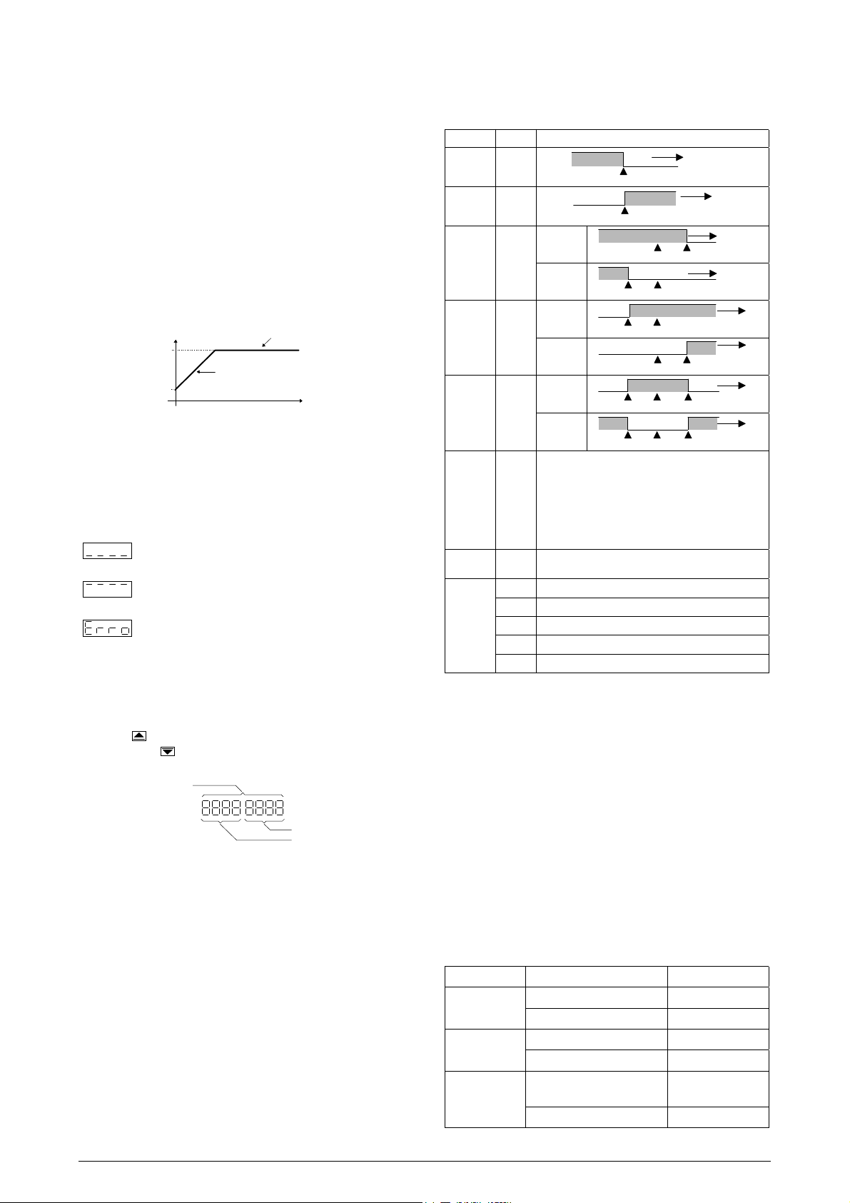
Table 2 shows eac h alarm function operation wit h their respective
code. Alarm 1 is used as an ex am pl e.
TYPE CODE ACTION
LOW
HIGH
LOW
differential
HIGH
differential
differential
or
deviation
Input
sensor
error or
heater
break
detection
End of
Program
Alarm
Functions
With alarm
inhibition a
power-up
0000
1111
2222
3333
4444
5555
6666
7777
8888
9999
10
10
1010
11
11
1111
Table 2 - Alarm functions and their identific at ion c odes
Alarm ON
SPA1
Alarm ON
SPA1
SPA1
Negative
SPA1
Positive
SPA1
Negative
SPA1
Positive
SPA1
Negative
SPA1
Positive
Alarm is ON whenever:
• Temperature is below/above selected range;
• Termocouple or Pt100 is broken;
• Pt100 is shorted;
• Pt100 is badly connected or wire im pedance is
too high;
• The heater resistence is broken
Activated when the programmed s oak time is run
out. Refer to item 4 of this manual.
Low limit alarm disabled at power-up
High limit alarm disabled at power-up
Differential low limit alarm disabled at power-up
Differential high limit alarm disabled at power-up
Differential alarm disabled at power-up
Alarm ON TEMPERATURE
Alarm
ON
SP + SPA1 SP
SP + SPA1 SP
Alarm
ON
Alarm ON
TEMPERATURE
SP + SPA1SP
Alarm ON
SP + SPA1SP
SP + SPA1SP - SPA1 SP
SP + SPA1SP - SPA1 SP
TEMPERATURE
TEMPERATURE
TEMPERATURE
Alarm
ON
TEMPERATURE
TEMPERATURE
Alarm
ON
TEMPERATURE
7. PID AUTO TUNE
During auto tune the temperat ure is controlled in ON/OFF mode at
the programmed Set Point (SV). Depending on the process
characteristics large oscillations above and below SV may occur and
auto tuning may take several minutes to be conc l uded.
The recommended procedure i s as follows:
SPA2”
SPA2SPA2
• Program a new SP close to the desi red final temperature
other than the present measured temperat ure.
• Enable the auto t une at the “Atvn
• Set 1 at the “rvn
rvn” prompt.
rvnrvn
Atvn” prompt by selecting 1.
AtvnAtvn
During auto tune large oscillations will be induced around the
setpoint. Make sure the process can accept these oscillations.
If aut o tuni ng results are not s atisf actory refer to t able 3 for manual
fine tuning procedure.
PARAMETER RESPONSE SOLUTION
Proportional Slow Response Decrease
Band Large Oscillation Increase
Integral Slow Response Increase
Rate Large Oscillation Decrease
Derivative Slow Response or
Decrease
Instability
Time Large Oscillation Increase
Table 3 - Suggestions for manual tuning of P ID param et er s
 Loading...