


N480D
Table of contents
 Loading...
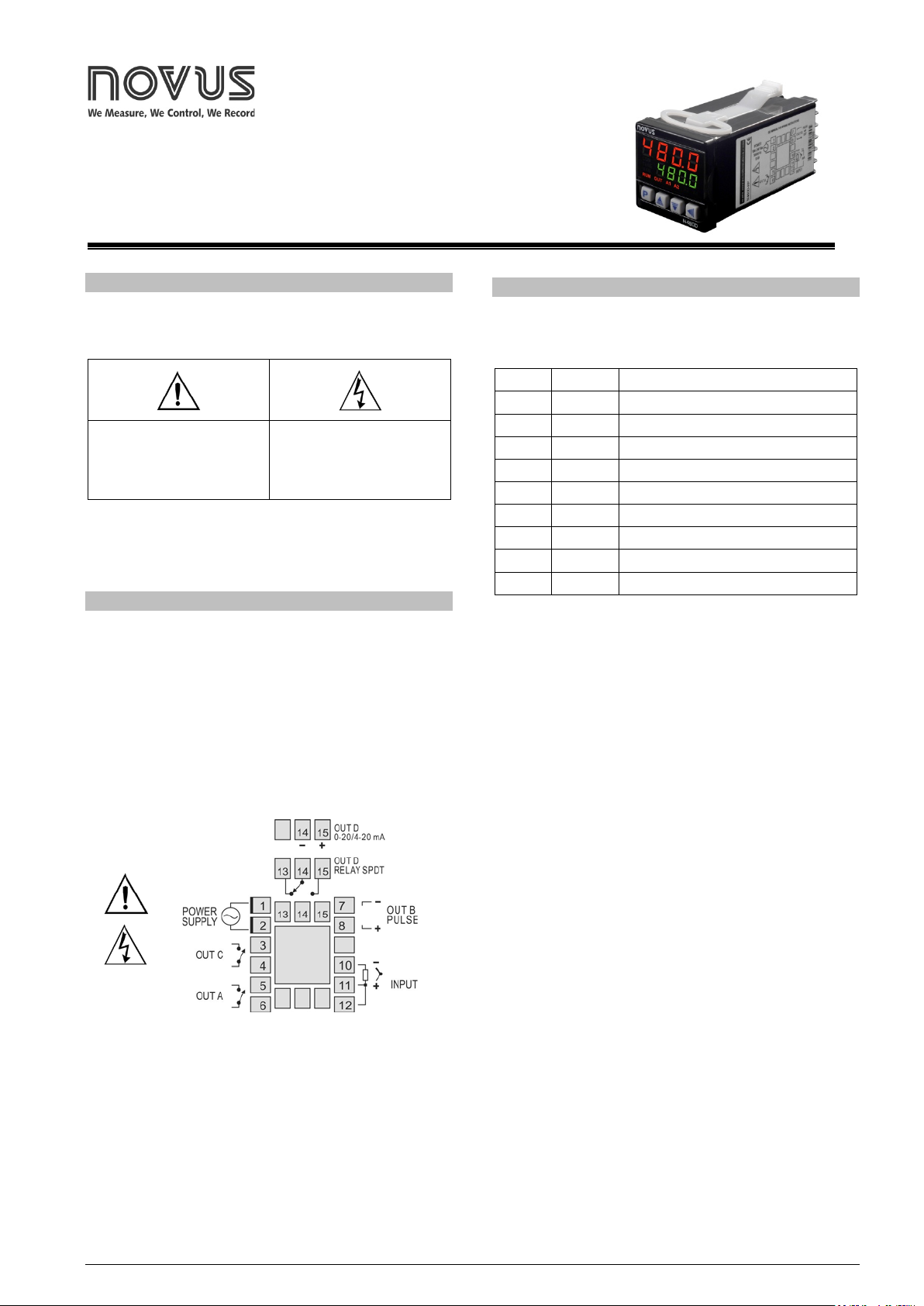
NOVUS AUTOMATION 1/6
Controller
N480D
UNIVERS
AL CONTROLLER – INSTRUCTIONS MANUAL – V5.0x
SAFETY SUMMARY
The symbols below are used on the equipment and throughout this
document to draw the user’s attention to important operational and
safety information.
CAUTION:
Read complete instructions prior
to installation and operation of
the unit.
CAUTION or WARNING:
Electrical Shock Hazard
All safety related instructions that appear in the manual must be observed
to ensure personal saf et y an d to p revent damage to eit he r t he instrument
or the system. If the inst rument is us ed in a manner n ot specified by the
manufacturer, the protection provided by the equipment may be impaired.
INSTALLATION
The controller must be installed on a panel with a square opening wi th
the specified di mensions. In order to fasten to the panel, remove the
clamps from the controller, introduce the controller in the panel’s
opening through the front and put the clamps back on the body of the
controller through the rear s ide of t he panel. Firmly press the clamps i n
order to fasten the controller to the panel.
The entire internal part of the controller can be removed from its
housing from the front of the panel, without needing to remove the
housing or clamps, or undo the con nections. To extract the controller
from its housing, hold it from the front and pull.
Fig. 1 shows the electrical terminals of the controller.
Fig. 1 - Elect rical connections of the cont roller
Thermocouples must be connected between pins 10 and 11. The
extension cable positive must be connected to terminal number 11.
Pt100 type sensors must be co nnected in 3 wires to termi nals 10, 11
and 12. For Pt100 in 2 wires, terminals 11 and 12 must be
interconnected. For adequate compensation of the cable length, the
conductors of this cable must have the same section (gauge).
RESOURCES
INPUT
Table 1 shows the types of temperature sensors accepted by the
controller and the respective code used to configure the controller.
TYPE CODE RANGE
J
Tc J
Range: -110 to 950 ºC (-166 to 1742 ºF)
K
Tc H
Range: -150 to 1370 ºC (-238 to 2498 ºF)
T
Tc T
Range: -160 to 400 ºC (-256 to 752 ºF)
N
Tc N
Range: -270 to 1300 ºC (-454 to 2372 ºF)
R
Tc R
Range: -50 to 1760 ºC (-58 to 3200 ºF)
S
Tc S
Range: -50 to 1760 ºC (-58 to 3200 ºF)
B
Tc B
Range: 400 to 1800 ºC (752 to 3272 ºF)
E
Tc e
Range: -90 to 730 ºC (-130 to 1346 ºF )
Pt100
Pt
Range: -199.9 to 850 ºC (-328 to 1562 ºF)
Table 1 - Types of sensors ac cepted by the controller
CONTROL OUTPUTS AND ALARM (OUTA, OUTB, OUTC AND
OUTD)
The controller can have 2, 3 or 4 outputs, which can be c onfigured as
control outputs or alarm outputs. These outputs are identified on t he
rear panel of the controller as OUTA, OUTB, OUTC and OUTD.
The output type (control or alarm) is defined in the controller’s
configuration. The output configurati on is individual and defined in the
ovt.A
,
ovt.B
,
ovt.(
, and
ovt.d
parameters respectively.
Output control is the output intended to control the process
temperature. It is possi ble to configure different out puts as the control
output, however, when the OUTD output i s configured as the Analog
Output Control, the other control outputs are disabled.
The output control is always off when the “
Erro
” message is shown
on the controller’s display, signaling a process failure, defect in the
sensor or connection error.
Alarm outputs are us ed for signaling and/or safety of the process. For
outputs defined as al arm output, it is also necessary to d efine the alar m
function (see the Alarm Function Description item of this manual).
USB INTERFACE
The USB interface is used f or CONFIGURING or MONITORING the
controller. The NConfig software must be used for the confi guration. It
makes it possible to create, view, save and open c onfigurations from
the equipment or files in your computer. The tool for saving and
opening configurations in files makes it possible to transfer
configurations between pieces of equipment and to make backup
copies. For specific models, the NConfig software also makes it
possible to update the firmware (internal software) of the controller
through the USB.
For MONITORING purposes you can use any supervisory software
(SCADA) or laboratory software that supports the MODBUS RTU
communication on a serial communi cations port. When connected to
the USB of a computer, the controller is recognized as a conventional
serial port (COM x). Use the NConfig software or co nsult the DEVICE
MANAGER in the Windows CONTROL PANEL to identify the COM port
that was assigned to the controller. Consult the mapping of the
MODBUS memory in the controller’s communications manual and the

N480D Controller
NOVUS AUTOMATION 2/6
documentation of your supervisory software to conduct the
MONITORING process.
Follow the procedure below to use the USB communication of the
equipment:
1. Download the NConfig softwa re from our website and ins tall it on
your computer. The USB drivers necessary for operating the
communication will be installed together with the software.
2. Connect the US B cable between the equipment and the com puter.
The controller does not have to be connected to a power suppl y.
The USB will provide enough power to operate the commu nication
(other equipment functions cannot operate).
3. Open the NConfig software, configure the communi cation and s tart
recognition of the device.
4. Consult the NConfig help desk fo r detailed instructions about how
to use it and solve problems.
The USB interface IS NO T SEPARAT E from the s ignal
input (PV) or the controller’s digital inputs and output s.
It is intended for temporary use during
CONFIGURATION and MONITORING periods. For the
safety of people and equipment, it must onl y be used
when the piece of equipment is completely
disconnected from the input/output signals. Using the
USB in any other type of connection is possible but
requires a careful analysis by the person responsible
for installing it. When MONITORING for long periods of
time and with connected inputs and outputs, we
recommend using the RS485 interface, which is
available or optional in most of our products.
CONFIGURATION AND OPERATION
Prior to first operation t he controlle r should be fully confi gured. The use r
must set basic parameters as temperature type (
TYPE
), the desired
control set point (
SP
), the alarms set points (
A1SP
and
A2SP
), etc.
The configuration ca n be performed directl y on the controll er or through
the USB interface. The NConfig software (free) is the configuration
management tool. Connected to the USB of a Windows comp uter, the
controller is recogni zed as a serial communi cations port (COM) runni ng
with a Modbus RTU protocol.
Through the USB interf ace, even if di sconnected f rom the power supply,
the configuration per fo rme d i n a piece of equipment can be c an be s ave d
in a file and repeated i n other piec es of equi pment that require t he same
configuration.
PARAMETERS FLOW CHART
The programming parameters are organized in 5 different levels
(parameter groups):
- Operation level
- Tuning level
- Program level
- Input level
- Calibration level
When Turned On, the controller displays the first screen of the
Operation Cycle. This screen shows on the red display (top), the
measured temperature value (PV ) and also the Set Point value of the
process (desired temperature for the process) on the green display
(bottom). During operation, the controller continues showing this
screen. In order to access other screens of this cycle, just press
.
All other Cycles are accessed when changes are required to the
controller’s configuration. In order to access these cycles just hold
down the
key for approximately three seconds. Af ter this ti me, the
controller displays the first paramete r of the next cycle (Tuning Cycle).
Holding the key down for three seconds, the nex t cycle (Input Cycle) is
also accessed.
Release the key in the des ired cycle. Press t he
key again to
access all other parameters of this c ycle. The key allows to return
parameters within the cycle.
The upper display shows the parameter and the lower dis play shows
the value of this parameter. T he and keys al low the operato r
to change the value of the shown parameter.
After accessing the last paramet er of the c ycle, the c ontroller returns to
the Operation cycle, indi cating the temperature proces s and SP. With
the keyboard inactive for more than 20 seconds, the controller also
returns to the Operation cycle.
The value of the changed parameter is s aved to permanent memory
and used by the controller when goi ng to the next parameter, or if no
key is pressed within 20 seconds.
PROTECTION OF CONFIGURATION
The controller allows to protect the configuration elaborated by the
user, avoiding unauthorized changes. The parameter Protection
(
PROt
), in the Calibration level, determines the protection strategy,
limiting the access to particular levels, as shown by the table below.
Protection
Level
Protected Cycles
1 Only the Calibration level is protected.
2 Input and Calibration level.
3 Program, Input and Calibration level.
4 Tuning, Program, Input and Calibration level.
5 All levels are protected.
Table 2 – Levels of Protection for the Configuration
Access Password
The protected levels, when acces sed, request the user to provide the
Access Password for granting permission to c hange the configur ation
of the parameters on these levels.
The prompt
PASS
precedes the parameters on the protected levels.
If no password is entered, the parameters of the protected levels can
only be visualized.
The Access Password is defined by the user in the parameter
Password Change (
PAS.(
), present in the Calibration level.
The new controllers leave the factory with the access password defined
as 1111.
Protection of the access password
The controller provides a security s ystem that helps prevent input of
numerous passwords trying to get the correct password. When 5 invalid
passwords in a row are identified, the controller stops accepting
passwords for 10 minutes.
Master Password
The Master Password is intended f or allowing the us er to define a new
password in the event of it being forgotten. The Master Password
doesn’t grant access to al l parameters, only to the Pas sword Change
parameter (
PAS(
). After defining the new password, the protected
parameters may be accessed (and modified) using this new password.
The master password is made up b y the last three digits of the serial
number of the controller added to the number 9000.
As an example, for the eq uipment with serial number 07154321, th e
master password is 9 3 2 1.
Loading...