

Page 1

Introduction........................................................... 2
In the Package.................................................................2
Product Registration.........................................................2
Using This Manual........................................................ 2
MIDI Controller Section Main Features......................... 2
Audio Section Main Features........................................ 2
Synthesizer Features.......................................................2
Quick Start Guide.................................................. 3
Conventions used in this Manual.................................... 3
Connecting Up To equipment......................................... 3
Stand Alone Operation.................................................... 3
Playing the Synthesizer.................................................... 3
Windows XP USB Driver Installation............................. 4
MAC OS X USB Driver Installation................................. 4
About ASIO on Windows XP........................................... 4
About Core Audio on MAC OS X..................................... 4
Selecting The X-Station as the Audio Device................. 5
Selecting The X-Station as the Audio Device in Cubase. ........ 5
The X-Station Control Panel........................................... 5
About Latency.................................................................. 5
Selecting The X-Station as the MIDI Device in Cubase.......... 6
Selecting The X-Station as the Audio Device in LOGIC.. ........ 6
Selecting The X-Station as the Audio Device in Reason.. ........ 7
Selecting The X-Station as the MIDI Device in Reason.. ........ 7
Controlling a VST Plug-In or Reason Instrument........................ 7
Factory Supplied Templates........................................... 7
Using The Programmable Template Controls................ 8
Sending A Snapshot Of The Controls............................10
Selecting A Sound On External MIDI Devices.............. 10
Changing The Action Of The Pitch / Mod Joystick.........10
Audio Connection And Setup.........................................10
Setting Up The Microphone Or Instrument Inputs.........10
Monitoring......................................................................10
Recording And Listening................................................10
Recording And Listening With Effects............................11
MIDI Tutorial......................................................... 12
Introduction................................................................... 12
How MIDI Ports Are Used............................................ 12
MIDI Messages............................................................. 12
Detailed Operation.............................................. 15
Front Panel Layout....................................................... 15
Modes And Menus....................................................... 16
Using Menus................................................................ 16
Entering Text................................................................ 16
The Template Common Menu...................................... 17
Template Edit Mode (Editing A Template).................... 18
The Template Edit ‘CC’ Pages..................................... 18
The Template Edit ‘NRPN’ & ‘RPN’ Pages.................. 19
The Template Edit ‘MMC’ Pages.................................. 19
The Template Edit ‘Note On/Off’ Pages....................... 20
The Template Edit ‘SYSEX MESSAGE’ Pages............ 20
The Template Edit ‘Program Change’ Pages............... 21
Using The X / Y Touchpad........................................... 21
Using The Footswitch Or Pedal................................... 22
Saving A Template To Memory..................................... 22
The Dual Multi Effects Processor................................. 23
The Delay Effect........................................................... 23
The Reverb Effect......................................................... 24
The Chorus Effect......................................................... 24
The Compressor........................................................... 25
The Distortion Effect..................................................... 26
The EQ Processor........................................................ 26
Advanced Features............................................. 27
Using The Transport Buttons....................................... 27
The Global Mode Menu.............................................. 27
Saving The Global Settings To Memory....................... 29
Upgrading The Operating System From MIDI............. 29
Synthesis Tutorial............................................... 30
Elements Of A Sound.................................................. 30
The Oscillators And Mixer............................................ 31
The Filter....................................................................... 32
Envelopes And Amplifier.............................................. 33
LFOs............................................................................. 35
Memories...................................................................... 35
Summary...................................................................... 35
The KS Synthesizer............................................. 36
Introduction................................................................... 36
Selecting KS Synth Patches........................................ 36
Editing A Synth Patch (Sound)..................................... 37
Saving A Synth Patch................................................... 37
Using Menus................................................................ 38
The Oscillator / Mixer Section..................................... 38
The Filter Section......................................................... 40
The LFOs Section........................................................ 41
The Envelopes Section................................................ 42
The Arpeggiator Section............................................... 43
The Effects Section...................................................... 44
The Oscillator Menu..................................................... 44
The Mixer Menu........................................................... 45
The Filter Menu............................................................ 47
The LFO Menu............................................................. 47
The Arpeggiator Menu.................................................. 49
The Sync Menu............................................................ 50
The Wheels Menu........................................................ 51
The Aftertouch And Breath Menu................................. 52
The Pan Menu.............................................................. 53
The KS Synth Mode Global Menu................................ 54
Routing MIDI To And From The KS Synthesizer.......... 54
The KS Synth General Settings................................... 55
Saving The KS Synth General Settings....................... 55
Appendix.............................................................. 56
Troubleshooting............................................................ 56
Using The X-Station With Reason............................... 57
Known Anomalies With Reason.................................. 57
Preset Template Listings...........................................58-61
The KS Synth Patch Preset Listings............................ 62
MIDI Implementation Chart........................................... 64
Safety CE Notices And Approvals................................ 65
CONTENTS
Contents
• 1 •
Page 2

Thank you for purchasing the X-Station controller keyboard and synthesizer. The X-Station is a state of the art product, it turns any com-
puter into a complete, professional music & audio production
workstation with hardware synthesizer, audio & MIDI interface,
control surface and effects processor – all in one package with
USB, PSU or battery power!
When used with a computer running a MIDI / Audio sequencer package
it will provide a superb, compact recording setup.
It may be used to control sequencers, popular software virtual instruments on a computer or traditional hardware instruments via either a
USB connection or a standard MIDI interface. In addition to the control
features it contains two audio pre-amplifiers together with a twin multieffects processor that allows the recording and replay of mono or
stereo audio signals to and from a computer.
The front panel provides a wealth of programmable controls arranged in
the format of a traditional synthesizer, each of which can be configured
to suit the needs of the instrument to be controlled. Each control can be
stored within a Template memory for instant recall at a later time.
The X-Station is equally at home in a live performance or studio situation where it can be used as a stand-alone synthesizer, MIDI controller
keyboard and recording device. Its comprehensive range of controls
may be used to dynamically alter any sound parameters precisely and
in real time whilst simultaneously recording and replaying stereo audio
data.
In the package
The X-Station package contains the following list of items.
• Main Keyboard X-Station Unit
• Power Supply
• User Manual
• USB Cable
• Set of Template Overlays
• X-Station Driver and Resources CD-ROM
When opening the package, please make sure all of the items above
are present, if not then please contact your local dealer.
www.novationmusic.com - Product Registration
Please take the time to register your new Novation X-Station. Point
your browser to www.novationmusic.com and complete the registration form. We advise that you visit www.novationmusic.com from time
to time to check for feature upgrades along with the appropriate documentation.
Using This Manual
This manual consists of seven sections; Introduction, Quick Start
Guide, MIDI Tutorial, Detailed Operation, Advanced Features,
Synthesis Tutorial and The KS Synthesizer. For easy reference, the
section name is printed at the top of each page. An Appendix is also
provided containing reference data.
It is assumed that the reader already has a basic knowledge of MIDI in
order to configure user Templates. Those with limited MIDI experience
may find the MIDI Tutorial useful. Although very little MIDI knowledge is
required to use the the X-Station with the factory programmed
Templates.
It is recommended that this manual is read in sequence chapter by
chapter.
The main features of both its MIDI controller capability and Audio operation are listed below.
MIDI Controller Section Main Features
X-Station features a superb two, four or five octave semi-weighted
velocity-sensitive keyboard with combined Pitch bend and Modulation
joystick. The keyboard is transposable up or down across the entire
MIDI note range and can transmit Channel Aftertouch.
A programmable X/Y touch pad surface for simultaneous control of multiple parameters is provided.
MIDI or USB operation. USB and MIDI may be used simultaneously. A
MIDI OUT port, a MIDI IN Port, a Foot pedal input socket and a
Footswitch input socket are available.
Power can be supplied by the USB port, Batteries or a 9V DC adapter.
A virtual synthesizer control panel layout comprising 28 buttons, 16
pots, 3 encoders and 9 sliders are assignable to each template. There
is no need for template labels for control of most synthesizers
Any front panel control may be configured to transmit on any MIDI
channel, to any destination utilising the comprehensive MIDI specification. Available options include Controller numbers, NRPNs, RPNS,
Bank Change, Program Change and definable System Exclusive
Strings. System Exclusive strings may be up to 20 bytes long. Control
data may be inserted anywhere within the System Exclusive message.
40 Template editable memories are available. Each Template contains
definitions for all front panel controls. Templates may be individually
named for easy reference and saved to/from an external sequencer via
MIDI Sysex bulk dumps
Audio Section Main Features
Two Novation high precision, low noise high bandwidth audio pre-amplifiers with phantom power and over 70 dB headroom deliver a warm,
clear signal typical of Novation's commitment to sonic excellence.
Complete multi-effects processors are available per input channel featuring simultaneous Reverb / Chorus-Phaser / Delay / Compressor /
Distortion and EQ.
Integrated USB low latency Audio and MIDI - Requires just a single
USB connection a computer.
High power independent headphone output with separate stereo converter for zero latency monitoring of input signal with or without effects
44.1 / 48 Khz 24 bit simultaneous 2 channel Audio input and output
operation
Driver software included to run on Windows XP or MAC OSX.
Synthesizer Features
The X-Station includes a 3-oscillator virtual analog synthesizer model
based on the renowned Novation KS-series and is 8-voice polyphonic.
The extensive control interface provides instant access to most parameters, making sound creation fast and intuitive. The synthesizer is totally integrated with computer recording setups: The stereo audio output is
sent straight through the USB cable onto the track into any ASIO-compatible sequencer.
There are 200 excellent factory sound programs which have been carefully crafted to cover most styles of music and programs can be easily
imported and exported into a sysex librarian.
INTRODUCTION
Using This Manual - Main Features - Conventions Used
• 2 •
Page 3
Conventions Used In This Manual
The word ‘Template’ refers to a collection of knobs, encoders and button settings and the function of the footswitch, pedal and X-Y touchpad.
Each Template is numbered from 1 to 40 and can be saved in the XStation’s non-volatile memory.
The word ‘Template Label’ refers to a coloured or blank ‘overlay’ which
sits neatly in the synthesizer control panel area.
The word ‘Preset’ refers to a Template configured at the factory to
showcase some of the powerful control possibilities. Preset Templates
may be over-written by new settings.
The word ‘Control’ refers to any of the front panel knobs, assignable
buttons, encoders, footswitch, foot pedal, joystick or the X-Y touchpad.
Within a single Template. Each control may be individually configured
to transmit various types of MIDI information addressed on any combination of the MIDI OUT / USB ports.
The word ‘Setting’ refers to any parameter which is edited from within a
menu.
The word ‘Synth Patch’ refers to a synthesizer memory which is
accessed while the X-Station is operating in the synthesizer mode.
Text in CAPITALS refers to a front panel Control or legend (even
though the name of the Control may actually be in lower case on the
front panel). It could be a knob, button, slider or rotary encoder.
Connecting Up To Equipment
In order to record or replay Audio or MIDI data it will be necessary to
connect the X-Station to a desktop or laptop computer with the appropriate MIDI and Audio recoding software installed.
When connected to a computer, power will be supplied directly from the
USB cable connection and it will not usually be necessary to fit batteries or plug into an external PSU.
Laptop Operation
When using a USB connection to power the X-Station from a Laptop
computer, the X-Station may not power up successfully
. This is due to
the X-Station not being able to draw enough power from the Laptop
computer.
The X-station requires approx 350mA of power to operate dependent
on various conditions. Switching on the phantom power, turning up the
monitor volume in the headphones and charging the batteries will add
to the power consumption. Although the USB specification dictates that
all computers should be able to supply 500mA of current which is
ample, some Laptops are not able to supply as much as this.
The solution is to either :
1) Power the X-Station from the supplied AC:DC power adapter.
2) Insert Dry or rechargeable batteries (recommended) .
3) Connect the X-Station to a powered USB Hub.
The X-Station will run on all types of ‘C’ size dry or re-chargeable cells.
Nicad batteries are rechargeable and will last approx 6 hours.
Alkaline batteries are normal high power dry cells. They are not
rechargeable and will last approx 12 hours.
Duracell batteries are extra high power, long life dry cells. They are not
rechargeable and will last approx 24 hours.
The X-Station will automatically sense the battery type and calculate
charging rate depending on the condition of the battery.
Fitting Batteries
Turn the X-Station upside down and unclip the battery compartment
using two fingers to push on the clips. Observe the connection diagram
imprinted on the plastic casing for 6 x ‘C’ cells to the right of the battery
cover. Fit the cells as shown in the diagram.
Power Operation
The X-Station may be configured to charge or not charge the batteries
(if rechargeable's have been fitted) from either the USB port, the external power supply or both. - See page 26 in the Global Menu Section for
details.
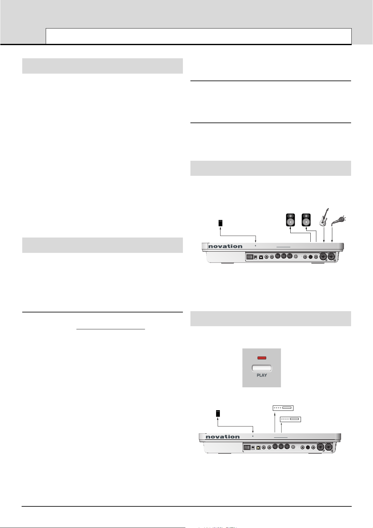
Stand Alone Operation
The X-Station may be used as a stand alone synthesizer, MIDI controller and/or a stand alone 2 channel Audio Mixer / Pre-amp with
effects processors. In this case it is not necessary to connect to a computer system.
STAND ALONE AUDIO SETUP
If powered loudspeakers are not available then the outputs must be
connected to an amplifier which in turn will power non active loudspeakers. If batteries are fitted - See previous page, then it is not necessary
to use the external power supply.
Playing the Synthesizer
In stand alone operation the synthesizer may be used for live performance. To activate the synthesizer, press the PLAY / SYNTH button
STAND ALONE MIDI SETUP
External sound modules may be directly connected to the MIDI output
sockets. If batteries are fitted, then it is not necessary to use the external power supply.
QUICK START GUIDE
Connecting Equipment - Stand Alone Operation - Playing the Synthesizer
• 3 •
Novation PSU 6
Power Supply
Powered Monitor Loudspeakers
Guitar Microphone
+
-
Power in
9V DC
MIDI
Expression
Sustain
pedal
pedalUSB
inout 2 SPDiff out Output 2 Output 1Headphones Input 2 Input 1out 1
-
X STATION 2525
SYNTH
Power Supply
+
-
Power in
Sustain
pedalUSB
9V DC
Sound ModulesNovation PSU 6
-
MIDI
Expression
pedal
inout 2 SPDiff out Output 2 Output 1Headphones Input 2 Input 1out 1
X STATION 2525
Page 4
QUICK START GUIDE
Driver Installation - Windows XP and MAC OS X
• 4 •
USB Driver Software Installation
In order to use all of the features of the X-Station it must be connected
to a computer system using the supplied USB cable. The USB connector is located on the rear panel. Before it can communicate with the
computer’s USB connection port, a special piece of software known as
a ‘USB driver’ must be installed.
The USB driver software converts information arriving at the computer’s
USB port into the correct format for use by the software Audio and MIDI
interface used by the computers operating system. Most music application software (Cubase, Logic, Cakewalk, Sonar, Digital Performer etc)
use this software Audio and MIDI interface to communicate with external hardware devices such as the X-Station or other keyboards and
sound modules.
The USB driver software is located on the supplied driver and resource
CD ROM and must be used with the Windows XP Operating System. If
using a PC with a different operating systems such as Linux, Windows
95, 98SE or 2000 USB support will not be available.
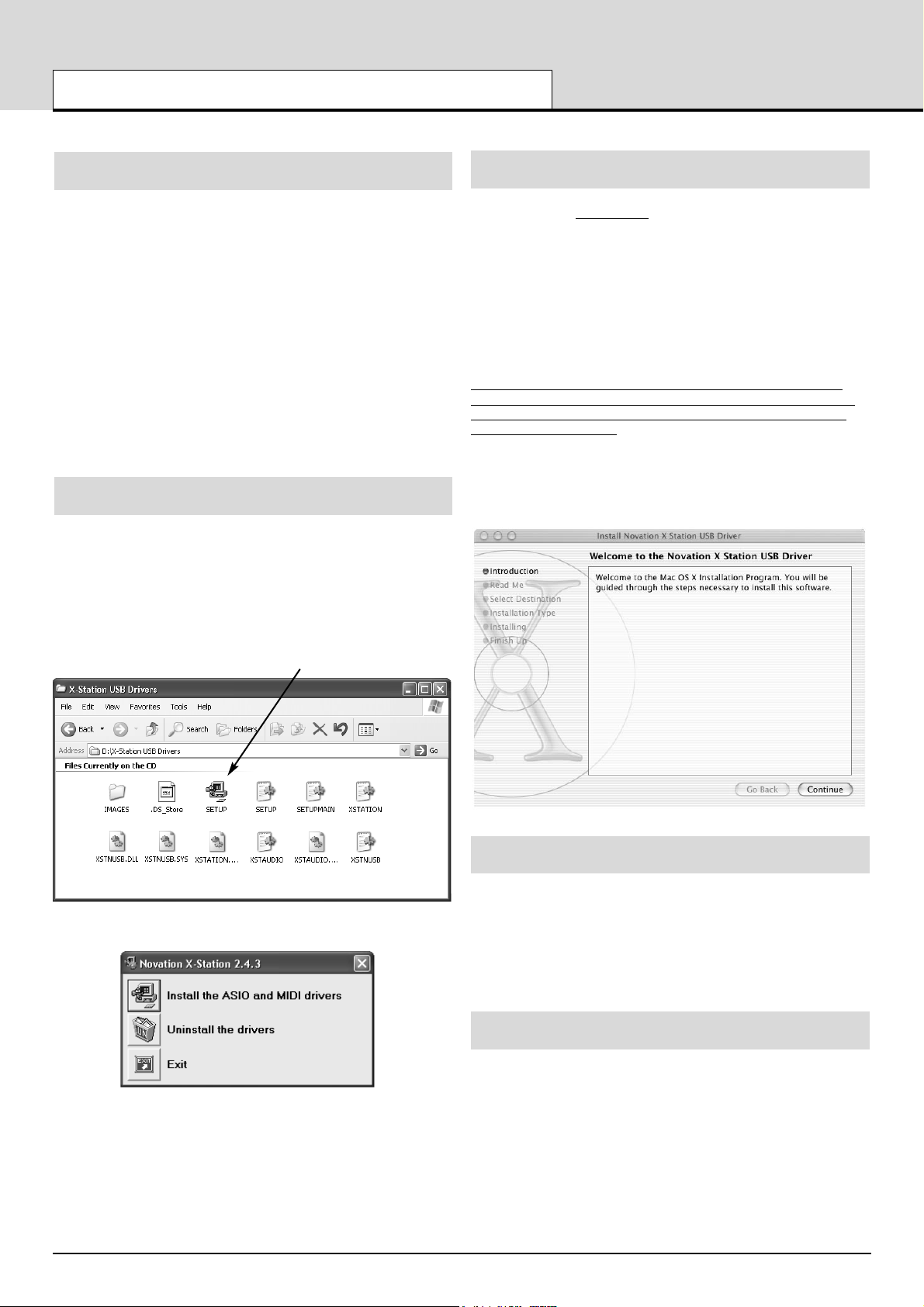
Windows XP USB Driver Software Installation
With the X-Station disconnected from the computer insert the X-Station
driver and resource disc. If the computer does not automatically show
an icon on the desktop for the CD, double click the 'my computer' icon.
The X-Station driver disc is labeled as 'X-Station'. Double click this icon
to show the contents of the disc.
Find and double click the directory 'X-Station USB Drivers'. Double click
the icon 'Setup' for the setup application. Depending on the views set in
Windows this icon may appear as ‘setup.exe’ in a list format.
The ASIO driver installation will begin.
Click the icon 'install the ASIO and MIDI drivers' Follow the on screen
prompts to install the X-Station drivers.
(if the X-Station or computer behaves erratically it may be neces-
sary to power it from an external PSU or batteries - See page 3)
MAC OS X Driver Software Installation
With the X-Station disconnected
from the computer, insert the CD
labeled ‘X-Station USB Drivers Resources’ into the CD Rom drive.
Drag the X-Station.hqx file to the desktop and double click this icon to
expand this. A file will appear on the desktop called 'X Station'. Open
this folder to reveal the X-Station installer. Double click the 'X-Station
Installer' icon and follow the instructions that appear.
It will be necessary to enter the administrator password to complete the
installation. At the end of the installation the computer will prompt to be
rebooted. Accept this prompt.
Important Notice
The X-Station core audio driver cannot be loaded if the X-Station is
turned on and connected to the computer when the computer is booting. Only connect the X-Station to the computer or turn on when the
computer has booted fully.
The X-Station core audio driver is called 'Novation X-Station'. This
should be selected as the core audio driver to be used from the appropriate Audio application, system preferences / sound or the application
'Audio MIDI setup'
About ASIO on Windows XP
Once the drivers are installed a special piece of software known as an
‘ASIO’ driver is available for use. This ASIO (Audio Stream Input
Output) driver allows for very fast direct communication between the XStation and the music sequencer/audio recorder (such as Cubase,
LOGIC, Sonar, etc.) and keeps audio delays down to a minimum.
If using a Windows system, for optimum performance this ASIO driver
must now be selected.
About Core Audio on MAC OS X
Similar to Windows systems, once the drivers are installed a special
piece of software known as a ‘Core Audio driver’ is available for use.
This also allows for fast direct communication between the X-Station
and the music sequencer/audio recorder (such as Cubase, LOGIC,
Sonar, etc.) and keeps audio delays down to a minimum.
If using a MAC system, for optimum performance the Core Audio driver
must now be selected.
Page 5
QUICK START GUIDE
Selecting the X-Station as the Audio Device
• 5 •
Selecting The X-Station as the Audio Device
Open the music application such as Steinberg Cubase, Emagic Logic,
Cakewalk Sonar, MOTU Digital Performer or Propellerhead Reason and
select the X-Station as the Audio and MIDI Device.
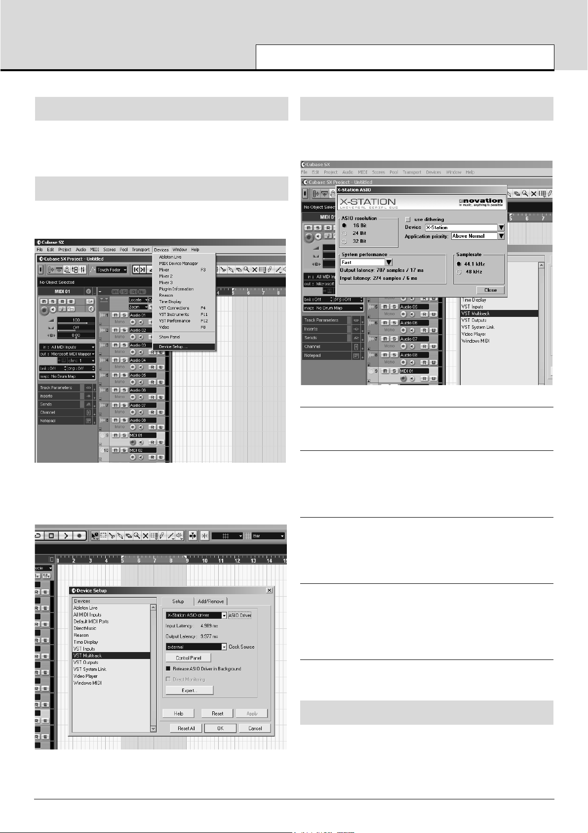
Selecting the X-Station as the Audio Device in Cubase SX or SX2
In Cubase SX or Cubase SX2 open the ‘Device setup’ window from the
pull down menu under ‘Devices’
In the ‘Device setup’ window, click on ‘VST Multitrack’ A display similar
to the following illustration will appear. There are drop down selection
boxes titled ‘ASIO Driver’ and ‘Clock Source’ Click on the ‘ASIO Driver’
selection box and select ‘X-Station’.
The X-Station Control Panel
Certain audio settings may be changed by clicking on ‘Control Panel’ in
the Device setup window. A panel will appear as illustrated below.
Devices
The X-Station will be selected as the default device. No other device
will be selectable.
Sample Rate
This will be set to 48kHz and cannot be altered. It confirms that the
speed of data flowing backwards and forwards through the USB cable
is 48kHz. This is not to be confused with Audio recording rates of 44.1
kHz and 48kHz.
Resolution
This will be set to 24bits and cannot be altered. It confirms that the size
of data flowing backwards and forwards through the USB cable is up to
24bits. This is not to be confused with the Audio recording bit depth settings of 16bit or 24 bits.
Application Priority
This will be set to ‘High’. It will tell the Audio system to take priority over
any other processes active in the PC. At ‘High’ priority it will allow an
uninterrupted stream of audio to flow from the sequencer. Setting this to
a lower priority will speed up other applications running on the computer but may cause clicks and glitches to occur in the audio stream
Use Dithering
Sound quality can be improved by adding a amount of ‘dither’. Leave
this set to ‘checked’
About Latency
Latency is the amount of time it takes for the Audio Input Analogue signal to be converted to a digital signal, sent along the USB system,
processed by the sequencer, then sent back along the USB system and
converted back to a Analogue output signal. A latency time of anything
more than approx 10mS will start to be noticeable.
Page 6
The amount of latency can be set by changing ‘System Performance’
drop down box options. The higher the specification (speed of CPU and
RAM memory) of the computer being used, the lower the latency may
be set. The choices are : Highspeed, Rapid, Fast, Normal and Relaxed.
The default setting is ‘Medium’ however for the best performance the
‘Highspeed ‘ option should be selected.
After setting this option experiment with recording and replaying audio see next few pages. If there are click and ‘pops’ appearing in the audio
signal then try setting the performance to the next lowest setting.
Selecting the X-Station as the MIDI device Cubase SX or SX2
In order to receive MIDI information from the X-Station into Cubase, the
X-Station must be selected as a MIDI device.
In the project window click on the ‘In’ drop down box and select ‘XStation’ (Emulated).
Now that the X-Station has been setup for Audio and MIDI turn to page
9 ‘Audio Connection and Setup’ for more information on using the
Audio features. Refer to page 7 ‘Controlling a VST insturment’ for more
information on using the MIDI control features.
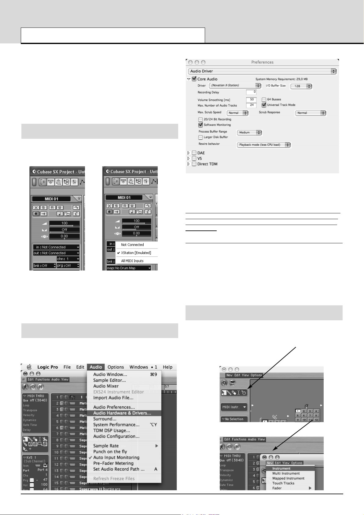
Selecting the X-Station as the Audio device in LOGIC
In LOGIC open the ‘Audio Hardware & Drivers’ window from the pull
down menu under ‘Audio as illustrated
In the ‘Audio Driver’ preferences window click on the small blue square
box labeled ‘Core Audio’ and the window will open up similar to the
illustration above. From the drop down box titled ‘Driver’ select
‘Novation X-Station’
NOTE
:
If just ‘X-Station’ is listed, turn the power off and then on again
to the X-Station. The computer will then recognise that the unit is con
nected and will make available as a selection the correct ‘Novation XStation’ driver.
Buffer Size Adjustment
The Core Audio driver temporarily stores input and output audio samples in buffers. Click on ‘I/O buffer size’ to adjust the buffer size. Larger
buffer sizes provide ‘padding’ against system activities that may interrupt the audio stream causing click and pops. Setting a smaller buffer
size will reduce audio latency. Experiment with this setting to optimise
audio performance for the system.
Click on OK and the X-Station will now be selected as the default
Audio device.
Selecting the X-Station as the MIDI device in LOGIC
In order to receive MIDI information from the X-Station into LOGIC, the
X-Station must be selected as a MIDI device. From the Main arrange
page click on the ‘Windows’ drop down menu and select ‘Environment’.
A page similar to the illustration will appear. Click on the drop down
arrow to select ‘MIDI Instrument’
Click on ‘New’ and select ‘Instrument’ from the drop down menu.
Selecting the X-Station in Cubase and LOGIC
• 6 •
QUICK START GUIDE
Page 7
The screen will display a new MIDI instrument Icon. Click the text at the
top of the selection and enter ‘ X-Station’. An X-Station Icon appears.
Close the environment window. The X-Station may now be selected
from the arrange page. Now that the X-Station has been setup for
Audio and MIDI turn to page 9 for more information on using the Audio
features. Refer to ‘Controlling a VST insturment’ on this page for more
information on using the MIDI control features.
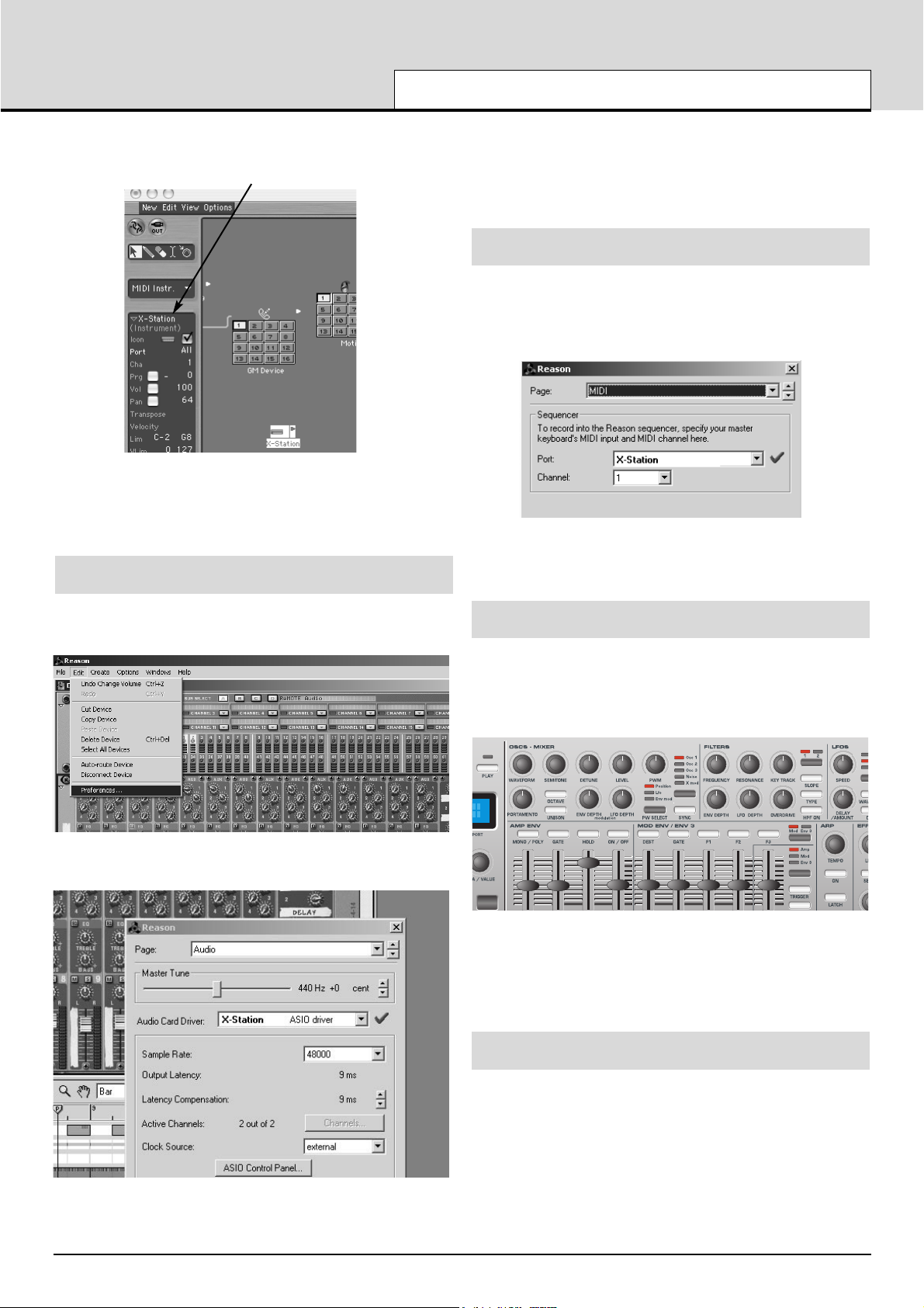
Selecting the X-Station as the Audio device in REASON
From the Main Reason screen, open ‘Preferences’ window from the pull
down menu under ‘Edit’
In the ‘Preferences’ window, click on the ‘Audio Card Driver’
drop down selection box and select ‘X-Station’ ASIO driver.
If precise Audio settings such as latency need to be adjusted, the XStation control panel may be selected and edited in a similar way to the
example shown for Cubase by clicking on the ’ASIO control Panel’ button. Click the ‘X’ in the top right hand corner of the window to close the
selection. The X-Station will now be selected as the default Audio
device.
Selecting the X-Station as the MIDI device in Reason
In order to receive MIDI information from the X-Station into Reason,
the X-Station must be selected as a MIDI device. Open the
‘Preferences’ window as shown previously. In the ‘Page’ drop down
selection click on the down arrow and select ‘MIDI’
Click the ‘X’ in the top right hand corner of the window to close the
selection. The X-Station will now be selected as the default MIDI
device.
Controlling a VST Plug-In Instrument or a Reason Instrument
The X-Station control panel is arranged in the format of a typical analogue subtractive synth design and Templates in the form of electronic
memories that contain the specific control information for each instrument are preset in the X-Station.
Numerous software or hardware synthesizers may be played directly
from the X-Station without the need for fitting a physical template
overlay. For clarity, a few software synthesizers or real instrument
emulations will benefit by placing one of the supplied labels over the
front panel synthesizer area.
Factory Supplied Templates
Manufacturer Insturment Template Name
Propellerheads Reason - Malstrom Malstrom
Propellerheads Reason - ReDRUM Drum
Propellerheads Reason - Mixer Mixer
Native Instruments FM7 FM7
Native Instruments B4 B4
• 7 •
Selecting the X-Station in LOGIC and Reason
QUICK START GUIDE
Page 8
QUICK START GUIDE
Using The programmable Template Controls
• 8 •
In addition to the 5 preprinted labels there are a further 3 blanks which
may be customised for any specific instrument. To fit a template label,
simply place over the synthesizer control panel area.
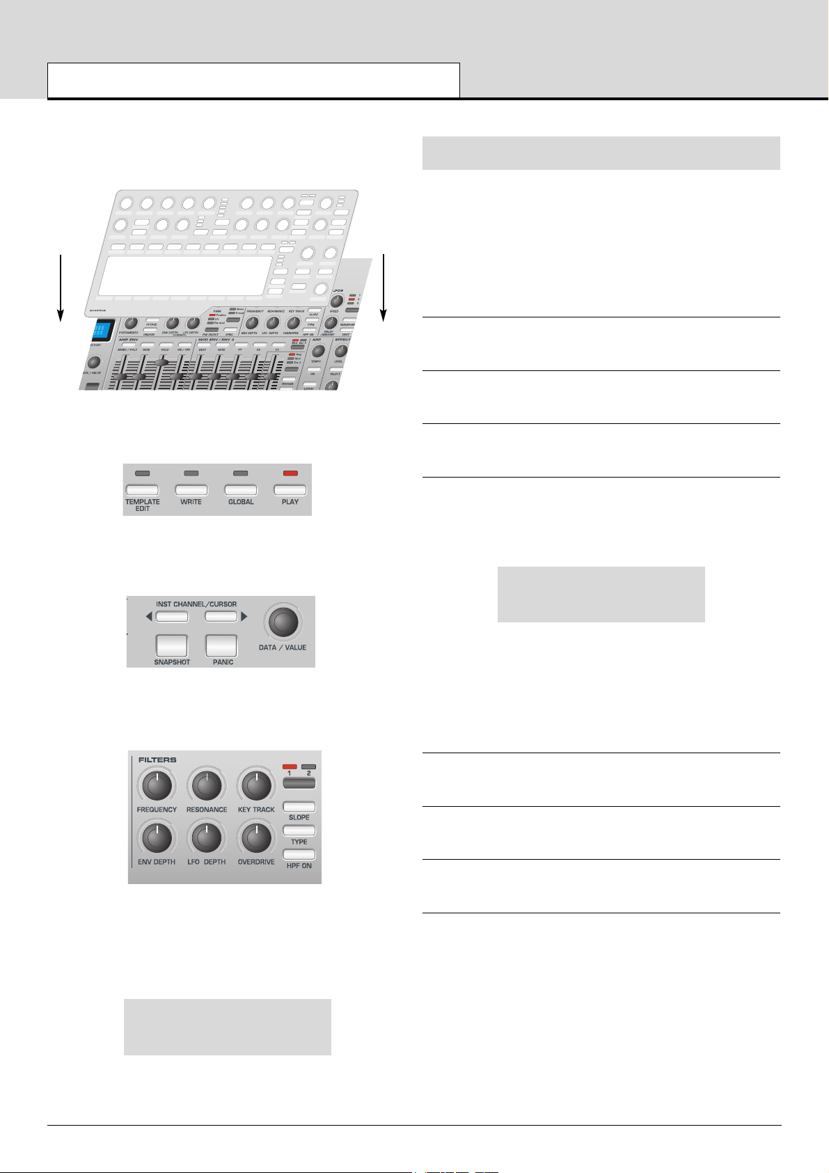
Check the front panel display area to see that PLAY mode is selected
(the LED above the button will be lit when in PLAY mode).
Rotate the encoder knob below the display to see the list of the electronic templates available. With each ‘click’ a new instrument electronic
template will be selected. Continue to rotate until the desired instrument
is selected.
Rotate the filter frequency control as shown in the illustration below
notice how the real-time values of the controls are displayed.
The display will appear similar to illustration below and the filter frequency knob of the software instrument will rotate on the computers
creen along with the corresponding change in sound.
Filter Frequency
87 CC74 1 U12
Using The Programmable Template Controls
Every Template contains definitions of the type of MIDI information to
be transmitted when any of the assignable encoders, knobs, sliders,
buttons or X-Y touchpad are used. It is not mandatory that every control
has to transmit MIDI information, so it is possible that controls in a
Template may be defined as ‘No Control’.
Data transmitted by a control is indicated on the bottom line of the display. When a control is moved, it will be one of the following :
Continuous Controller
This is indicated by CC followed by the controller number.
Non-Registered Parameter (NRPN)
This is indicated by NRPN. There is no controller number displayed.
Registered Parameter (RPN)
This is indicated by RPN. There is no controller number displayed.
MIDI Machine Control
The screen shows MMC. There is no controller number displayed.
The screen display when a control moved is slightly different for buttons
using MMC :
Stop
1 MMC 1 U12
This is similar to the normal display shown when other types of MIDI
information are transmitted, except that the top line displays the type of
MMC command defined, while the bottom line at the left is the MMC
number of the command defined for the button.
Only buttons can be assigned to send MMC. When MMC is used, there
is no Control name used or displayed.
Note ON / Note OFF
The screen shows NOTE. There is no controller number displayed.
System Exclusive
The screen shows SYSEX. There is no controller number displayed.
Program Change
The screen shows PROGC. There is no controller number displayed.
Pitch Bend
The screen shows PBEND. There is no controller number displayed.
.
ReMOTE
audio template: blank
Page 9
QUICK START GUIDE
Sending Snapshots - Selecting External Sounds - Joystick - Audio Connection
• 9 •
Sending A Snapshot Of The Controls
It is possible to send a snapshot of current values to a connected MIDI
device by pressing the SNAPSHOT button while in Play Mode.
The data values sent are the ones stored for each control in the
Template data, (except for where a control has been moved) since the
Template has been loaded. If a control has been moved, the new value
represented by the position of the altered control is sent instead of the
stored value.
Be aware that, when a snapshot is sent, the current position of a
control might not bear any relation to the data value sent in the
snapshot if that control has not been touched since the Template
was selected.
For each control, the snapshot data is sent to the USB / MIDI port as
assigned to the control in the within the template data. Any MMC functions assigned to buttons are not sent in a snapshot. It is possible for
any Template to be set to automatically send a snapshot as soon as the
X-Station is placed into Play Mode. See page 15 for details.
Selecting A Sound On External MIDI Devices
In Play Mode, it is possible to select sounds on external MIDI devices
directly by using the PROGRAM UP / DOWN buttons. When a
PROGRAM UP / DOWN button is pressed, the display shows :
MIDI Prog Chang:
104
and a Program Change message is immediately sent. If either PROGRAM UP / DOWN button is held down for about one second, the
action auto-repeats, automatically incrementing or decrementing the
value sent. Once the button is released, the display reverts back to
showing the current Template’s name after about half a second.
Use the BANK UP / DOWN buttons to transmit a MIDI Bank Select
message to a MIDI device. When pressed, the display shows :
MIDI Prog Bank:
05
and a Bank Select message is immediately sent. After about half a second the display reverts back to showing the current Template’s name.
Note that the X-Station always sends Bank Select messages using
CC32. This is used by most MIDI equipment, but some equipment may
use CC0 messages. If this option appears not to change the Program
bank on the MIDI device, it may be necessary to define another template control to transmit CC0 values. See pages 16-17 for details on
assigning controller numbers to controls.
Changing The Action Of The Pitch / Modulation Joystick
To suit different playing styles, the travel of the front to back movement
of the modulation Joystick may be set to ‘Sprung’ or ‘Static’.
When shipped form the factory it is set to ‘Sprung’. Moving the joystick
forward will always result in the stick returning to the forward position,
therefore setting any data assigned to it back to an original value.
For example, if it is set to control the vibrato depth on a voice or oscillator, then letting go of the stick will remove any of the vibrato effect.
To set the stick to ‘Static’, turn the X-Station upside down. Push down
on the plastic slider below the joystick assembly, and move the plastic
switch to the opposite end of the cavity. To return to ‘Sprung’ mode,
repeat the procedure in the opposite direction.
Setting to static allows the stick to be left in a position where modulation is applied without having to keep a finger pressed on the stick. This
can be useful when the mod wheel is assigned to control the speed
switch of an organ rotary speaker.
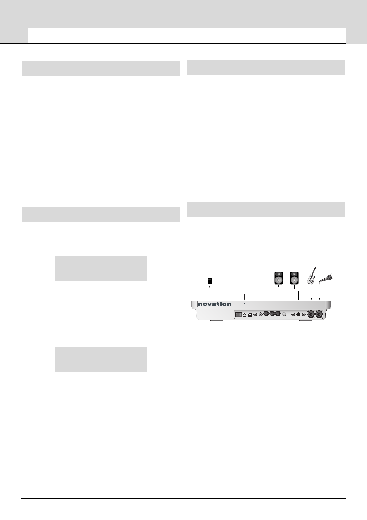
Audio Connection And Setup
At this stage it is assumed that the X-Station is connected to a computer and both the computer and the X-Station are switched on.
Now that the software drivers have been installed, connect the XStation to the other system devices. These could be as shown in the
illustration.
This is a basic Audio connection. It will allow the recording of external
signal sources such a those from a microphone or guitar and also allow
the replay of Audio data from a sequencer to a pair of loudspeakers
and headphones. (MIDI notes played from the keyboard and knob
movements will also be sent to the sequencer).
If batteries are not fitted then an external power supply (Novation
PSU6) may need to be connected - See page 5. If this is the case, shut
down the computer, turn off the X-Station and fit the batteries. Ensure
the X-Station is still connected to the computer via the USB cable and
switch both the X-Station and the computer on at the same time.
Connect any other devices such as sustain and expression pedals (if
required) to the rear panel jacks. Finally, switch on the power to any
other powered devices such as the loudspeakers.
Each of the two Audio Inputs provided can except a wide range of
audio signals - from a low output level condenser microphone all the
way up to a line level CD player. The line output jacks deliver an unbalanced audio signal which will directly drive an audio mixer, an audio
power amplifier or powered loudspeakers.
Novation PSU 6
Power Supply
Powered Monitor Loudspeakers
Guitar Microphone
+
-
Power in
9V DC
MIDI
Expression
Sustain
pedal
pedalUSB
inout 2 SPDiff out Output 2 Output 1Headphones Input 2 Input 1out 1
-
X STATION 2525
Page 10
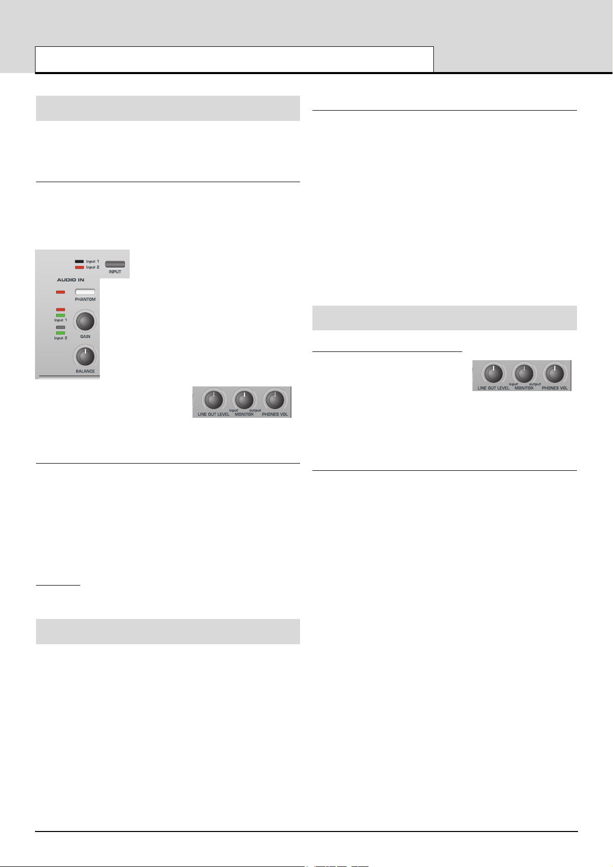
Setting Up The Microphone Or Instrument Inputs
Both of the audio inputs allow either 1/4” jack plugs or XLR type connectors to be plugged in and the input sensitivity of the high quality preamplifiers can be adjusted to accommodate different signal levels.
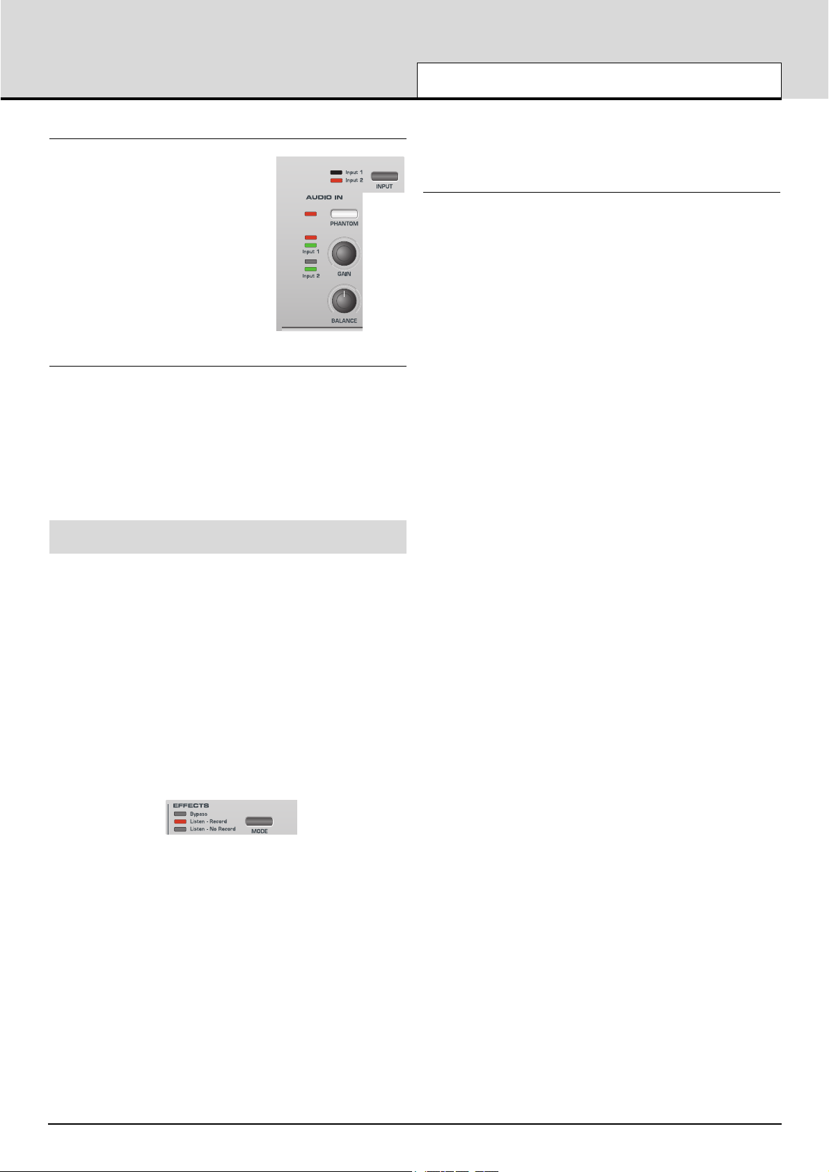
Adjusting the Input Gain
Select Input Channel 1 by pressing the INPUT button. With a microphone plugged into Channel 1, turn the GAIN knob until the GREEN
LED next to the GAIN knob is fully lit when speaking or singing into the
Microphone and the RED LED occasionally flashes.
This will set the gain of the preamplifier to
the correct level for the Microphone such
that it will not distort or be too quiet when
recording.
Check that the Audio level that is being
sent from the X-Station to the recording
software is not too low or too high. To do
this, look at the input meters within the
recording software.
Adjust the LINE OUT LEVEL knob to
ensure that the level on the input
meters does not go too high (consult
the recording software documentation
for more information on this).
Using Phantom Power
If the Microphone being used is a ‘condenser’ type it will need to have a
DC voltage (normally 48V) sent to it before if will generate any audio
output signal. Some microphones have their own power supply to do
this but if not, the X-Station can supply the necessary voltage.
With the appropriate input channel selected (LED lit) press the
PHANTOM button and the LED to the left of the button will light
indicating that phantom power is being sent to the microphone on the
selected channel.
WARNING : Some Ribbon, Dynamic and Electret type Microphones
should NOT
have phantom power delivered to them and if so may be
damaged! - Check with the documentation supplied with the
Microphone so see if it requires phantom power.
Monitoring
The process whereby audio material already recorded into the audio
sequencer is listened to by the artist or recording engineer while blended with any new material such as a voice or an instrument is known as
Monitoring.
In order that a Microphone used for recording a vocal does not pick up
any of the already recorded sound tracks of, for example drums and
bass back into the vocal track, headphones are usually used by the
vocalist. A ‘mix’ is sent to the Headphones of the live Microphone
sound with the previously recorded material.
In a typical setup a separate audio mixer would be required to mix the
signal from the live Microphone with the one already recorded. Since
the X-Station provides independent headphone level and monitor knobs
an external audio mixer is not required.
Zero latency monitoring
The input signal from either microphone or instrument is converted to a
digital signal and is sent to the computer via a USB connection. It then
goes into the music software application and is sent back for listening.
Using the ASIO driver software installed earlier, the time delays this
process causes are kept to a minimum. It may however be annoying to
the artist when making a new recording since this slight delay is perceived as an ‘out of time’ feel, or as an echo if this delay time is long.
The X-Station has a zero latency monitoring feature whereby a knob is
provided to balance the previously recorded material with the live sound
to be recorded.
There is also a knob ‘LINE OUT LEVEL’ to control the level of the signal going to powered Loudspeakers. With control over the output level
to the Loudspeakers, it is very quick to switch between listening back to
a new recording (for example a new vocal take has been added) to
reverting to a Headphones only monitoring situation for recording a further vocal.
Recording And Listening
Listening
Check that the Microphone(s),
Headphones and Loudspeakers are
plugged in and setup as described on
the previous page. If the session is
purely for listening then turn up the LINEOUT knob and press the PLAY
button on the software music sequencer. Any audio information that has
been previously recorded should be heard in the loudspeakers. Notice
that the headphones level may also be individually controlled by the
PHONES VOL knob.
Mono Recording
If the Microphone and Loudspeakers are in the same room turn the
LINEOUT knob fully anti-clockwise to ensure no previously recorded
audio information is being sent to the loudspeakers.
Rotate the MONITOR knob fully anti-clockwise to listen to the
Microphone input signal only. Put on the Headphones and talk into the
Microphone. It should now be possible to hear the microphone in the
Headphones.
If not, check that the monitor button is pressed on the software music
sequencers track (consult the music software documentation on how to
do this) When recording a new track, in this example a vocal, press the
record and play button (consult the music software documentation on
how to do this) on the sequencer and begin to talk or sing into the
microphone.
The balance between the previously recorded tracks and the new live
vocal may be adjusted to suit by rotating the MONITOR input to output
knob.
Using Channel 1 and with the BALANCE knob set fully anti-clockwise,
the live vocal will be sent to the left output of the Headphones or
Loudspeakers. Rotate the BALANCE knob to position it anywhere in the
stereo field. Once the recording is complete, the finished, updated
recording can be played back and listened in either the Headphones or
Loudspeakers or both by adjusting the LINE OUT LEVEL and
PHONES VOL knobs.
QUICK START GUIDE
Setting Up Inputs - Monitoring - Recording And Listening
• 10 •
Page 11
Dual Mono Recording
If it is desired to record two different inputs
simultaneously - for example a guitar and
a vocal, repeat the setup process and set
the input gain for both the microphone and
the guitar independently. Use the INPUT
button to switch between each input to set
the signal level using the LED’s Begin
recording and use the BALANCE knob to
move the left to right position of either of
the two inputs. Within the sequencer set
one track to Input Channel 1 and the other
track to Input Channel 2.
Stereo Recording
Plug in a Stereo source (such as a CD player) and press the STEREO
button. Both input LED’s will light. Use the GAIN knob as previously
described to set the appropriate input level.
The BALANCE knob behaves in a different way when recording a
Stereo device. Rotating it fully anti-clockwise will result in the signal
being summed into a MONO signal. Rotating it fully clockwise will result
in a WIDE Stereo signal As in the previous examples the balance
between the previously recorded tracks and the new live stereo input
may be adjusted to suit by rotating the MONITOR input to output knob.
Recording And Listening With Effects
Most modern software audio sequencers allow the input signal to be
monitored with low latency but this is only a copy of whatever is
plugged into the audio input(s).
An outstanding feature of the X-Station is the ability to record and / or
monitor complete with effects, such as Reverb, without the need for an
external hardware effects box or without the need to engage additional
effects processors within the recording software.
This is particularly useful when recording vocals since the artist will normally prefer some amount of reverb in the headphones during a performance. It usually will help him/her to envisage a live situation with
some ambience in the room.
There are three options with regard to monitoring and recording the
effects:
1. Bypass
This option will disable the effects section and the computer system will
record any audio data 'dry' - that is, an amplified version of the signal
appearing at the audio inputs. Any monitoring of the signal by headphones or on the main left and right outputs will also be 'dry'
2. Listen - Record
This option will enable the effects section and the computer system will
record any audio data 'wet' - that is, an amplified version of the signal
appearing at the audio inputs together with any of the audio effects
(such as reverb). Any monitoring of the signal by headphones or on the
main left and right outputs will also be 'wet'
3. Listen - No Record (Listen wet and Record Dry)
This option will enable the effects section BUT the computer will record
any audio data 'dry' - that is, an amplified version of the signal appearing at the audio inputs. Any monitoring of the signal by headphones or
on the main left and right outputs will be 'wet'. This would be consid-
ered as a very useful option when, for example, recording a voice the
signal can be recorded 'dry' but the artist will be able to listen (monitor)
his or her performance with effects applied.
Adding Reverb
In the effects section press the UP/DOWN buttons to select the Reverb
effect - the corresponding LED will light. Adjust the LEVEL knob for the
desired amount of Reverb effect. The effects processors are powerful
multi effects type whereby one of each different effect may be applied
simultaneously if desired
See section ‘ Detailed Operation - The Dual Effects Processor’ on page
21 for more information on audio control and using the effects processor on recordings.
QUICK START GUIDE
Recording And Listening With Effects
• 11 •
Page 12

Introduction
MIDI is an acronym for Musical Instrument Digital Interface. The MIDI
standard was devised in the early 80’s as a means for allowing musical
instruments to communicate with each other as well as with other
devices such as sequencers and computers. Before the advent of MIDI,
it was often very difficult (if not impossible) for instruments to effectively
communicate with each other, especially if they had been made by different manufacturers. Nowadays, most types of electronic musical
equipment are equipped with a MIDI interface fitted as standard, including synthesizers, drum machines, samplers, sequencers, computers
and even some effects units.
The MIDI standard allows many different instruments to be controlled at
once (say from a sequencer or a controller keyboard such as the XStation) using the same network of MIDI cables. Each instrument in the
MIDI chain is usually assigned its own unique MIDI channel and will
only respond to information that it may receive on that particular channel. The MIDI standard allows for sixteen different channels to be
assigned to the various instruments in a MIDI network. This means that
it is normally possible to have up to sixteen instruments playing simultaneously within a MIDI system.
Some people may feel that being restricted to just sixteen MIDI channels might be a little limiting, especially if they are composing very complex pieces of music. However, most current sequencers, MIDI ports for
computers and master keyboards offer a neat way around this problem.
They can offer several different MIDI outputs, each of which is treated
as a separate MIDI system in its own right with its own set of sixteen
MIDI channels. The X-Station may use any combination of its MIDI
OUT & USB ports for this purpose.
How MIDI Ports Are Used
The X-Station has three MIDI ports, one labeled ‘In’ and two ‘Outs’.
Additionally, there is a USB port which acts in a manner similar to a
combined MIDI IN / MIDI OUT. Each type of MIDI port has a specific
purpose :
MIDI IN ports
These are used by the X-Station to receive incoming MIDI information.
It is possible to configure the X-Station to immediately re-transmit this
MIDI information to any of the X-Station MIDI Out ports or to the USB
port. This is detailed on page 25. The X-Station can process incoming
MIDI from the MIDI IN port or the USB port simultaneously.
MIDI OUT Ports
These can transmit any MIDI information which might be generated by
the X-Station. For example, if a note was played on the X-Station keyboard or one of the controls were moved on the front panel. This MIDI
information is intelligently merged with any MIDI being re-transmitted
after arriving at the MIDI IN / USB ports.
USB Port
This port is used to connect the X-Station to a computer that features a
USB port. It can be regarded as a special port that can send and
receive MIDI information simultaneously. It is the most convenient way
of connecting to a computer, avoiding the need to connect two sets of
standard MIDI cables between the X-Station and a separate MIDI interface. The information which flows through the USB connection conforms to the same Message format as standard MIDI.
Since MIDI information flows in one direction only along a standard
MIDI cable, it is not possible to have a MIDI In socket connected to
another MIDI In socket. If this were done the MIDI network would simply not work! In fact, the only two routings allowed are MIDI Out to MIDI
In or MIDI Thru to MIDI In.
Keyboard Controllers such as the X-Station are used to generate MIDI
data for controlling other instruments. Examples of other common MIDI
controllers are drum percussion pads or footswitch controllers. Of
course, the X-Station is capable of much more than just controller keyboard duties!
MIDI Messages
The X-Station is capable of transmitting various types of MIDI events.
These are as follows :
Note Messages
A note message is transmitted every time a key on the X-Station keyboard is pressed down or released. When a keyboard note is pressed
down, the MIDI message also includes velocity information. This represents how hard the key was pressed down. This velocity value can be
used to add dynamics to the sound, depending on how hard the note
was played.
It is also possible to configure buttons on the front panel to transmit
Note messages such that a Note On message is sent when the button
is pressed and the corresponding Note Off message sent when the button is released. This is detailed on page 18.
Control Change Messages
These messages are commonly used to alter synthesizer parameters
by MIDI. In many of the Preset Templates, it is actually Control Change
messages which are sent when the front panel controls are moved.
The MIDI specification allows for 128 different types of controller message. These are often referred to as Continuous Controllers (CC0 to
CC127).
Some controllers are rigidly defined by the MIDI standard for specific
functions. For example, CC1 is always used for the modulation wheel.
Therefore, whenever the X-Stations modulation joystick is moved, it will
transmit MIDI control change information using CC1. All makes of synthesizers will also use CC1 for modulation wheel data.
The Continuous Controller numbers rigidly defined include 0, 6, 32, 38,
96. 97, 98, 99, 100, 101 & 120 - 127. These are used for specialised
specific purposes.
Many Control Change numbers have no set purpose within the MIDI
specification. For example, whenever a Novation KS series Filter FREQUENCY knob is moved, it will transmit using CC105. There is no
guarantee however that other makes of synthesizer will use this control
change number for the same purpose.
A CC MIDI message can contain a data value anywhere in the range 0
to 127.
Use of Control Change messages is detailed on page 16 .
Non-Registered Parameter Messages
Some synthesizers (such as the Novation KS series) actually have
many more than 128 different parameters that can be transmitted by
MIDI, but because the number of different types of control change message is limited to just 128, a more complicated arrangement for transmitting additional parameters is used. This arrangement is known as
Non-Registered Parameter Numbers (NRPNs for short).
NRPNs actually consist of three MIDI control change messages
grouped together, rather than a single MIDI control change message
which is normally used. The first two CC messages define the NRPN
number of the message. CC98 is used to specify the least significant
byte (LSB) of the NRPN number and CC99 is used to specify the most
significant byte (MSB) of the NRPN number.
MIDI TUTORIAL
Introduction - MIDI Ports - MIDI Messages
• 12 •
Page 13

To calculate the MSB, divide the full NRPN number by 128. The
remainder is the LSB value.
Once the LSB & MSB of the NRPN number have been sent, CC6
(known as Data Entry) immediately follows. This contains the actual
data value to be sent in the NRPN.
As an example of how this works, consider sending a data value of 10
on NRPN number 260. The three grouped Continuous Controller messages would be :
CC98 (NRPN LSB) 4 (260 modulus 128 = 4)
CC99 (NRPN MSB) 2 (260 / 128 = 2)
CC6 (Data Entry) 10 (data value)
Many synthesizers do not use NRPNs. Consult your synthesizer manual for details of which NRPNs are recognised.
The use of NRPNs is detailed on page 17.
Registered Parameter Messages
These are known as RPNs and are similar in format to NRPN messages. CC100 is used to define the RPN LSB and CC101, the RPN
MSB (usually zero). As for NRPNs, CC6 contains the actual data value.
RPN numbers assigned by the MIDI specification are :
0 Pitch Bend sensitivity
1 Fine Tuning
2 Coarse Tuning
3 Tuning Program Select
4 Tuning Bank Select
Many synthesizers do not use RPNs. Consult your synthesizer manual
for details of which RPNs are recognised.
The use of RPNs is detailed on page 17.
Pitch Bend Messages
These messages are transmitted whenever the X-Station’s joystick is
moved along the X axis. It is also possible to define the X - Y touchpad
to transmit Pitch Bend.
As the name implies, pitch bend messages are used to move sounding
notes up or down in pitch.
Aftertouch Messages
These messages are transmitted by some keyboards whenever
already-held down keyboard notes are pushed further or wiggled.
Aftertouch messages can be used to add extra expressiveness to a
sound, for example introducing an extra vibrato effect.
The MIDI specification actually defines two different types of aftertouch
message; Mono and Poly. The type transmitted by the X-Station is the
Mono type. This affects all sounding notes simultaneously.
Poly aftertouch includes information in the MIDI message about which
keyboard note was used to trigger the aftertouch effect, allowing individual sounding notes to be affected. Poly aftertouch is actually very rarely
found nowadays as only a very few synthesizers ever used it.
Program Change & Bank Select Messages
These messages are used to remotely select sounds on a synthesizer.
The MIDI Specification only allows a MIDI program change message to
select one of 128 different sounds. When the MIDI specification was
originally designed, this was rarely a problem since synthesizers seldom had more than 128 memories. Modern synthesizers such as the
Novation K-Station offer many more memories than this (the K-Station
for example, actually has 400 memories divided into four ‘banks’ of 100
memories each), so it is often convenient to send a MIDI program
change preceded by an additional MIDI message which specifies which
‘bank’ of sounds the following Program Change message will select
from.
The Bank Select MIDI message used for this purpose is actually a MIDI
Control Change message. CC32 is the control change number used by
Novation and most manufacturers, but a few manufacturers may use
CC0 instead. Consult the synthesizer manual for details on the Bank
Select Continuous Controller number used.
For example to select Program A100 on the Novation Supernova, the
following MIDI messages would be needed :
CC32 5 (5 selects Program Bank A on the Supernova)
Prog Change 100
Synthesizers which implement Bank Select usually require that the
appropriate Bank Select message is sent before a following Program
Change message. Synthesizers not implementing Bank Select need
only receive a Program Change message.
Warning : Many synthesizers will only accept a Program Change
message if a Bank Select message has been received first !
Bank Select Messages may be sent from the X-Station by either using
the DATA / VALUE encoder from from within Play Mode (CC32 is
always sent) or by defining a control within a Template to transmit CC0
or CC32 as appropriate.
Program Change messages may be sent from the X-Station by either
using the PROG / PAGE UP / DOWN buttons from within Play Mode or
by defining a control within a Template to transmit Program Change.
Channel Messages
All of the different types of MIDI messages outlined so far include information detailing which MIDI channel was used when the message was
transmitted. MIDI channel messages will only affect receiving devices
using the same MIDI channel. For example, a Pitch Bend message
sent using MIDI channel 1 would have no effect at all if it were received
on a synthesizer set to respond on MIDI channel 2.
Some MIDI messages do not include any MIDI channel information
defined in them. Some examples of these are :
System Exclusive Messages
This is special type of MIDI message, often referred to as ‘Sysex’.
System Exclusive messages can actually contain any type of data,
depending what the synthesizer manufacturer decides to put in it! The
only constraint with system exclusive messages is that they always
contain certain header information which is exclusively used by the
manufacturer (and usually the relevant synth model as well). What this
effectively means is that a MIDI device will only accept a system exclusive message designed especially for it. For example, If the Novation
K-Station should receive a system exclusive message transmitted by a
different make of synthesizer, the message would simply be ignored.
Similarly, other makes of synthesizer will ignore any system exclusive
messages originally sent by a Novation K-Station.
Unlike other types of MIDI message, System Exclusive messages do
not have a fixed length. The MIDI specification allows any number of
data bytes (each with a value between 0 to 127) between a Sysex
Start byte and a Sysex End byte. The first data bytes in a Sysex mes-
sage always contain the manufacturer ID. This is unique to each
Synthesizer manufacturer.
Some manufacturers (such as Yamaha) employ short Sysex messages
for sound editing purposes rather than using Control Change messages. The X-Station can send short System Exclusive messages containing up to 20 bytes (including the manufacturer ID). See page 18 for
details.
The X-Station employs system exclusive messages for two distinct purposes. Firstly, they can be used to back up all of the X-Station memories and global data. This feature is extremely useful in building up a
Template library or a Synth program library on a computer or for making
a safety copy of data in case the worst should happen. Data backup is
discussed in detail on Page 25 in the Advanced Features chapter.
MIDI TUTORIAL
MIDI Messages
• 13 •
Page 14

Secondly, Novation also use system exclusive messages to enable an
X-Station to update its entire operating system via MIDI. The latest
operating system for the X-Station is always available at the Novation
web site. From there, it can be downloaded and installed with a proprietary installation utility. See page 27 for details.
MIDI Machine Control (MMC) Messages
These are are a range of messages designed to communicate with
sequencers and recording devices. In reality, MMC commands are actually specialised forms of System Exclusive messages (termed
‘Universal’) which are designed to be recognised by any manufacturer
supporting MMC.
When MMC commands are assigned to X-Station controls, only the
MMC command need be specified. The remainder of the MMC
Universal System Exclusive message is automatically constructed by
the X-Station. See page 17 for details on assigning MMC.
A MIDI Implementation Chart provides a concise way of telling at a
glance which MIDI messages an instrument will transmit and respond
to. A MIDI Implementation Chart for the X-Station can be found on page
57.
MIDI TUTORIAL
MIDI Messages
• 14 •
Page 15
DETAILED OPERATION
Front Panel Layout
• 15 •
PITCH
MOD
X STATION 2525
Noise
X mod
Position
Lfo
Env mod
Compress
Distortion
EQ
Chorus
Reverb
Delay
Listen - Record
Listen - No Record
Bypass
outputinput
Input 2
Input 1
Input 1
Input 2
1
2
3
Osc 1
Osc 2
Osc 3
Amp
Mod Env 3
Mod
Env 3
21
LFOS
EFFECTS
FILTERSOSCS - MIXER
EFFECTS
AUDIO IN
MOD ENV / ENV 3
AMP ENV
ARP
GLOBAL PLAY
TOP LINE
PROGRAM
OCTAVE
SNAPSHOT PANIC
INST CHANNEL/CURSOR
TEMPLATE
COMMON
BANK/PAGE
TEMPLATE
EDIT
WRITE
ON
LATCH
TEMPO
SPEED
DELAY
WAVEFORM
LEVEL
SELECT
CONTROL
SLOPE
TYPE
HPF ON DEST
RESONANCE
ENV DEPTH LFO DEPTH OVERDRIVE
FREQUENCY
PORTAMENTO ENV DEPTH
SEMITONE DETUNE PWM
UNISON
LFO DEPTH
WAVEFORM
PW SELECT
OCTAVE
SYNC
LEVEL
TRIGGER
REPEAT
MONO / POLY GATEGATE HOLD ON / OFF DEST F1 F2 F3
GAIN
PHANTOM
MONITORLINE OUT LEVEL PHONES VOL
LEVEL
INPUT STEREO
MODE
MENU BOTTOM LINE
VALUE CC# MIDI CHAN MIDI PORT
DATA / VALUE
KEY TRACK
/AMOUNT
ATTACK RELEASESUSTAINDECAY RELEASE VELOCITYSUSTAINDECAYATTACK
BALANCE
modulation
1
8
9
7
10
12
13
2 3 4 5 6
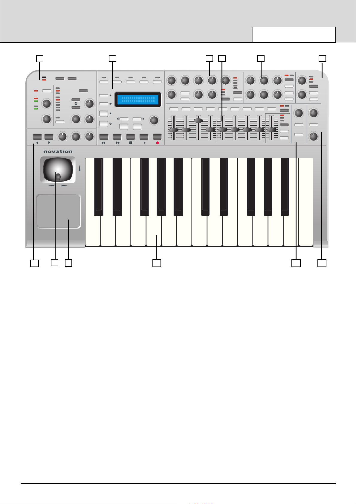
1. Audio Input and Effects Section
Audio input channel and gain selection. Effects
control editing and selection.
2. Main control and Display Section
Mode control, template selection and transport controls.
Menu selections and display cursor control.
3. Synth control - Oscillator Section
Osc selection, Osc waveform, Osc Pitch and Modulation
controls. Voice Portamento and Unison controls.
4. Synth control - Envelopes Section
Sliders assignable to Amplifier, Filter and Modulation
envelopes. Assignable envelope control buttons.
5. Synth control - Filter Section
Filter Cutoff,Resonance, Key tracking, Env and LFO
modulation, type and mode selection
6. Synth control - Lfo Section
LFO selection, Waveform, Speed and delay controls
7. Octave select and Monitor Section
Keyboard Octave transpose buttons. Output Level volume, Headphone monitor volume and Input / 0output mix
control.
8. Combined Modulation / Pitch Bend Joystick
Selectable sprung / non sprung modulation
9. Programmable X / Y Touchpad
Up to 4 programmable parameters 2 for the X axis (horizontal) and 2 for the Y axis (vertical).
10. Aftertouch Sensitive Semi-Weighted Keyboard
X-Station 25 has a 25 note keyboard (2 octaves),
X-Station 49 has a 49 note keyboard (4 octaves),
X-Station 61 has a 61 note keyboard (5 octaves).
12. Synth control - Arpeggiator Section
Arp speed and mode controls
13. Synth control - Effects control Section
Effects send level and additional control.
Page 16
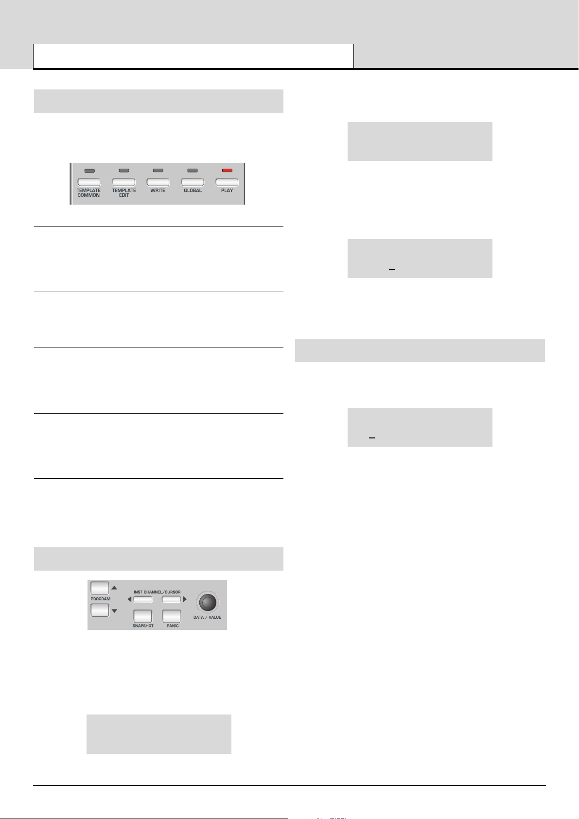
Modes And Menus
The X-Station has five modes of operation. Each mode is selected by
pressing a button in the Main display of the front panel. The LED above
each button indicates which mode is currently active.
Template Common Mode
Template common mode is used when editing settings which apply to
the Template as a whole such as the Keyboard MIDI channel. This
mode is selected by pressing the TEMPLATE COMMON button. See
page 15 for details.
Template Edit Mode
Template Edit Mode is used to edit / change how each individual programmable control functions within a Template. This mode is selected
by pressing the TEMPLATE EDIT button. See page 16 for details.
Global Mode
Global mode is used to edit the various settings which apply across all
Templates. This mode is selected by pressing the GLOBAL button. A
second press of the global button will display the KS synth specific
global features. See pages 26 -27 and page 52 for details.
Play Mode
Play mode is used for used for normal performance. All control values
will be seen when any controls are moved in Play Mode. This mode is
selected by pressing the PLAY button. Play Mode is also automatically
selected when the X-Station is switched on.
KS Synth Mode
In this mode, the X-Station can be used as a Novation KS Synthesizer.
This mode is selected by pressing the PLAY button once more while
already in Play Mode. Pressing the PLAY button once more toggles
back to Template Play Mode. KS Synth Mode is discussed in detail in
The KS Synthesizer chapter on pages 34 to 53.
Using Menus
All operational modes except Play Mode allow various settings to be
altered from within menus. There is only one menu available in each
mode and they are all accessed in the same way using the controls
shown above.
When Play Mode is initially accessed, the standard Template display
shows the Template’s name and location. For example :
Novation 1
V-Station
In all modes, the first menu page is automatically selected when the
mode is activated. In Template Edit Mode for example, the first menu
page would be :
Control Type:
CC
In menus, the current value of a setting is always shown on the bottom
line of the display, justified to the right. The value of a setting is always
edited by turning the DATA / VALUE encoder.
Sometimes, a menu page will have several settings shown together on
the bottom display line. For example, in the sysex editing menu :
SYSEX MESSAGE:
F0 30 2A 20 4D
Here there are five settings shown simultaneously. A cursor indicates
which one is currently selected for editing with the DATA / VALUE
encoder. The CURSOR LEFT / RIGHT buttons are used to move the
cursor and select a different setting for editing.
Entering Text
When entering text, a cursor indicates the character in a name currently
selected for editing. For example, when naming a control :
Control Name:
Filter Cutoff
The DATA / VALUE encoder alters the character at the current cursor
position. The CURSOR LEFT / RIGHT buttons select a different character in the name for editing.
While editing text, the five TRANSPORT buttons provide the following
useful functions :
REWIND button : Upper Case Alphas
FAST FORWARD button : Lower Case Alphas
STOP button : 0 - 9 Numbers
START button : Special Chars
RECORD button : Replaces current character
with a space character
A further press of the BANK / PAGE UP button allows the next menu
page to be selected. In the Template Select & Global menus, once the
last menu page has been reached, the BANK / PAGE UP button will
have no further action. Similarly, the BANK / PAGE DOWN button reselects the previous menu page.
In the Template Edit menu, once the last menu page has been reached,
pressing BANK / PAGE UP loops the menu around to the first page
again.
Note : The content of some menu pages will vary according to a setting’s value elsewhere. This particularly applies to the Template Edit
Mode menu where the types of pages available will vary according to
the current value of the Control Type setting found on the first menu
page.
Each of the menu pages for the various operational modes will now be
described in detail.
DETAILED OPERATION
Modes And Menus - Using Menus - Entering Text
• 16 •
Page 17
The Template Common Menu
The menu in Template Common Mode is used to alter settings which
apply to the Template as a whole and are not specific to a single programmable control.
The menu pages available are :
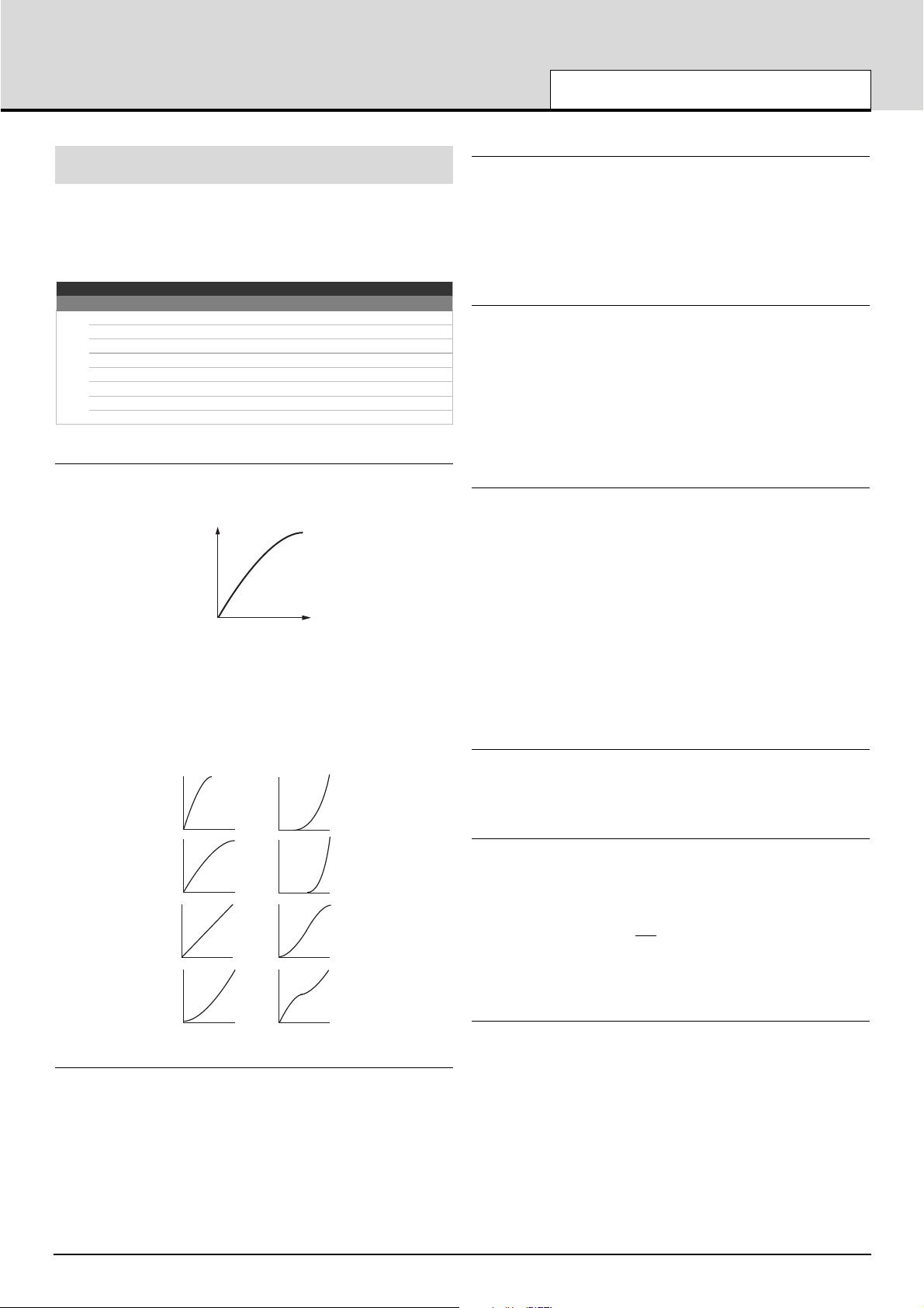
Keyboard Velocity Curve (Menu Page 1)
Selects one of eight velocity tables governing the velocity response
when playing the keyboard. The velocity curves available are :
Curve selection No. 3 is the default setting for the factory pre-programmed templates and should be acceptable for most playing styles. If
a softer touch is required (lighter key strokes give the same velocity
output) then curve No.2 or even No.1 would be suitable. If a harder
response if required, then selecting No. 4, 5 or 6 would give the desired
result.
Keyboard MIDI Channel (Menu Page 2)
Sets the MIDI channel used for transmission when the keyboard is
played. Note: The MIDI channel used for the Pitch and Modulation joystick is programmable within the template.
This channel value is over-ridden if the Override MIDI Channel setting
on page 4 of this menu or in Play Mode is used.
Keyboard MIDI Port (Menu Page 3)
Determines which MIDI / USB port is used to send the MIDI information
generated by playing the keyboard.
Eight different combinations of output ports can be selected, with any
multiple combination possible. A ‘U’ shown on the display indicates the
MIDI will be sent to the USB port, a ‘1’ that the MIDI OUT (1) port will
be used and a ‘2’ indicates that the MIDI OUT (2) port will be used.
Override MIDI Channel (Menu Page 4)
This setting provides an override MIDI channel that is used instead of
the channel defined for each of the programmable front controls. The
override channel also affects the X-Station keyboard and Modulation /
Pitch Bend joystick.
When this is set to Off, the channel override feature is disabled and
each control will transmit using its own MIDI channel settings.
Note that the MIDI Inst Chan setting in Play Mode always has a higher
priority than the value of this setting as defined here.
Touchpad X Type (Menu Page 5)
Sets how the touchpad behaves when a finger is placed on the pad.
The X type defines the horizontal plain.The data / value encoder scrolls
through three types of 'Spring' modes.
No Spring - As soon as a finger is released from the touchpad, the
value of the touchpad will remain. A subsequent touch to the pad will
result in a slew to the new touch value.
Spring Left - As soon as a finger is released from the touchpad, the
value of the touchpad will slew back to the Start position ie to the ‘Low
Value’ (see page 16 for details).
Spring Center - As soon as a finger is released from the touchpad, the
value of the touchpad will slew back to the center position. ie the mean
value of the low and high values. (this can be found by adding the low
and high values together and then dividing by two).
Touchpad Y Type (Menu Page 6)
This display is identical to touchpad X type above except that the Y
type defines the behavior in the vertical plain with the appropriate display messages.
Auto Snapshot Send (Menu Page 7)
Specifies whether a snapshot of all control data values are transmitted
as soon as Play Mode is activated.
For each control, the snapshot data is sent to whatever USB or MIDI
port that is defined for the control in the Template data. Any MMC functions assigned to buttons are not
sent in a snapshot.
Note that when the X-Station is turned on, it always automatically starts
up in Play Mode. However, at this time, an auto snapshot is not trans-
mitted, even if this setting is On.
Not Synth Type Template (Menu Page 8)
With certain templates such as a Mixer and Drum machine type it is
more convenient to have a configuration where the four buttons above
the AMP ENV sliders and the five buttons above the MOD ENV sliders
are all switched to a second function by pressing the MOD / ENV button.
For example, with any Drum type templates, pressing this button
(Renamed SOLO/MUTE) re-assigns all nine buttons to SOLO’s or
MUTE’s for each channel. When creating a ‘Not synthesizer’ type template, set this to ‘On’ for this alternative function to be active.
DETAILED OPERATION
The Template Common Menu
• 17 •
Template Common Menu
Page Function Display V alue
1 Keyboard Ve locity Curve Velocity Curve: 1…8
2 Keyboard MIDI channel Keyb MIDI Chan: 1…16
3 Ke yboar d MI DI Por t Keyb MIDI Port: ---…U12
4 Overide M IDI Channel Over ide MIDI Ch : Off, 1 …16
5 Touc hpad X Type Touchpad X Type No Spring..Spring Centre
6 Touc hpad Y Type Touchpad Y Type No Spring..Spring Bottom
7 Auto Snapshot Send Auto Snapshot On, Off
8 Not Synth Type Template Not Synth: On , Off
Velocity
Force
1
5
7
8
6
2
3
4
Page 18

Template Edit Mode (Editing A Template)
The menu in Template Edit Mode is used to define the settings of
each of the programmable front panel controls which comprise a
Template. The pages which make up the menu are dif
ferent according
to the type of MIDI information to be transmitted by the control. For
example if a CC type of control is chosen, the menu path will be different for that of a SYSEX type control
It is always the last touched control which is edited. If no control has
been touched since the X-Station was turned on, the default control
selected for editing will be Pot one (the knob at the top left corner). The
controls which can be edited are any of the programmable knobs, buttons or sliders to the right of the display, the pedals, the joystick, the X /
Y touchpad or any of the Transport buttons.
Because the displayed menu pages are always in context according to
the type of MIDI message used by the currently selected control (and in
some cases, the type of control itself), the information shown on the
display may change if a new control is touched during the editing
process.
The first page of the Template Edit Menu is always displays / prompts
for the type of control. In the example below it is a ‘CC’ type.
Control Type:
CC
The type of MIDI information that will be transmitted for the control is
specified in this page. The options available depend upon the type of
control selected for editing. These are :
CC
Continuous Controller. Any controller number can be used, however
the MIDI standard defines controller numbers 0, 6, 32, 38, 96, 97, 98,
99, 100, 101 & 120-127 for specific specialised purposes. These values
should not be used unless the consequences upon the connected MIDI
device are appreciated.
NRPN
Non-registered Parameter Number.
RPN
Registered Parameter Number.
MMC
MIDI Machine Control. This can only be selected for buttons.
Note On/Off
Note On / Note Off message. This can only be selected for buttons.
SYSEX MESSAGE
System Exclusive string. This can contain a value altered by the control. A string of up to 20 bytes can be defined for each control.
Program Change
Program Change message. This can only be selected for buttons.
Pitch Bend
Pitch Bend. This can only be selected for the X / Y Touchpad.
No Control
The control will transmit no MIDI when touched. There are no further
menu pages available if this option is selected.
The Template Edit ‘CC’ Pages
The following Menu pages are available if Control Type on menu page
1 is set to ‘CC’ :
Controller Number (Menu Page 2)
Sets the MIDI continuous controller number assigned to the control.
Any controller number from 0 to 127 can be assigned, however the
MIDI standard defines controller numbers 0, 6, 32, 38, 96, 97, 98, 99,
100, 101 & 120-127 for specific specialised purposes. These values
should not be used unless the consequences upon the connected
MIDI device are appreciated.
Value Display Type (Menu Page 3)
Determines whether values for the control are displayed in a signed (64 to +63) or unsigned (0 to 127) format. Internally, values are always
stored within the Template data as 0 - 127. This setting only determines
how the values are displayed on-screen.
A value of 0 unsigned is exactly the same as -64 signed, 60 unsigned is
the same as -4 signed, 68 unsigned is the same as +4 signed and so
on.
For example a display type of 0 - 127 would be used for a control that
is altering a volume setting and a type -64 to +63 would be used for a
pan left and right control.
Low Value (Menu Page 4)
Sets the lowest data value which can be transmitted by the control. This
would normally be 0 however it might be desirable to set a range
between 20 and 30 for the whole range of a slider. In this case the
lower value would be set to 20. It may be desired to reverse the action
of a particular control. This can be done by swapping high and low values, eg a normal control could have a low value of 0 and a high value
of 127. To reverse the action of this control, set the low value to 127
and the high value to 0.
High Value (Menu Page 5)
Sets the highest data value which can be transmitted by the
control.This would normally be 127 (or +63) however it might be desirable to set a range between 20 and 30 for the whole range of a slider.
In this case the higher value would be set to 30.
Button Action Type (Menu Page 6)
This menu page is only accessible if a button has been selected as the
control for editing. Otherwise, pressing PAGE UP from menu page 5 will
bypass this page.
This setting determines how the button will behave. There are four
available options :
Normal
The High data (as on Menu page 5) value will be transmitted when the
button is pressed. Data is only sent when the button is pressed, not
when it is released.
DETAILED OPERATION
Template Edit Mode - The Template Edit ‘CC’ Pages
• 18 •
Template Edit 'CC' Pages
Page Function Display Value
2 Controller Number Controller Num: 0…127
3 Value Display Type Display Type: 0 - 127, -64 to +63
4 Low V alue Low Value: 0 - 127 or -64 to +63
5 High Value High Value: 0 - 127 or -64 to +63
6 Button Action Type Button Type: Norm al…Step
7 Pot / Slide r Control Type Pot/Slider Ctrl: Jum p, Pickup
8 MIDI Chan nel MIDI Channel: 1…16
9 MIDI Ports MIDI Ports: ---…U12
10 Control Name Control Name: Text string
Page 19
Momentary
The High data (as on Menu page 5) value will be transmitted when the
button is pressed. The Low data value will be transmitted when the button is released.
Toggle
Pressing the button alternates between transmitting the High data value
and the Low data value. The high value is sent on the first button press.
Data is only sent when the button is pressed, not when it is released.
Step
On the first button press, the Low data value is transmitted. Each subsequent button press increments the data value until the High data
value is transmitted. The next button press after this results in the Low
data value being sent and so on. Data is only sent when the button is
pressed, not when it is released.
These button options allow a range of applications to be easily controlled. For example if there is a button on a software synthesizer that
has three options, then it may respond to a MIDI continuous controller
number with a range of 0 - 2 (This gives 3 states, 0,1 & 2). When programming a button to control the software, the low value would be set
to 0 (Menu page 4 - detailed above) and the high value would be set to
2 (Menu page 5 - detailed above). The step option would then be
selected.
Pot / Slider Control Type (Menu Page 7)
This menu page is only accessible if a knob or slider has been selected
as the control for editing. Otherwise, pressing PAGE UP from menu
page 6 will bypass this page.
This setting determines how the knob or slider behaves. There are two
possible options :
Jump
The knob or slider will immediately transmit MIDI when moved.
Pickup
The knob or slider will only transmit MIDI once it has passed through
the position represented by the control’s data value as stored in the
Template.
Note: All the controls in the factory preset templates are set to ‘Jump’
mode.
MIDI Channel (Menu Page 8)
Sets the MIDI channel which the control will use for transmission.
MIDI Port (Menu Page 9)
Determines which MIDI / USB port is used to send the MIDI information
generated by touching the control.
Eight different combinations of output ports can be selected, with any
multiple combination possible. A ‘U’ shown on the display indicates the
MIDI will be sent from the USB port, a ‘1’ that the MIDI OUT (1) port will
be used and a ‘2’ indicates that the MIDI OUT (2) port will be used.
Control Name (Menu Page 10)
Here, a name is given to the control for easy reference. This is the
name displayed on the screen when a Template control is moved (see
page 5).
Control Name :
Amp Env Attack
A cursor indicates which character in the name can be altered. Use the
CURSOR buttons to select a different character position and the DATA /
VALUE encoder to alter the character in the name.
While a name is being edited, the five TRANSPORT provide the following useful functions :
REWIND button Upper Case Alphas
FAST FORWARD button Lower Case Alphas
STOP button 0 - 9 Numbers
START button Special Chars
RECORD button Replaces current character with a space
character
The Template Edit ‘NRPN’ & ‘RPN’ Pages
The following Menu pages are available if Control Type on menu page
1 is set to ‘NRPN’ or ‘RPN’
LSB Number (Menu Page 2)
Sets the LSB (Least significant byte) of the NRPN / RPN number.
MSB Number (Menu Page 3)
Sets the MSB (Most significant byte) of the NRPN / RPN number. For
NRPN numbers less than 128 (such as those used by the Novation
Supernova 1 Rack and Nova Laptop), ensure that this setting is zero.
The remaining menu pages are exactly the same in operation as those
already described for the Template Edit ‘CC’ menu pages. These are
described in detail on pages 16 & 17.
The Template Edit ‘MMC’ Pages
The following Menu pages are available if Control Type on menu page
1 is set to ‘MMC’. These are only available if the control being edited is
a button and would typically be used to control a sequencer or recording device :
Device ID (Menu Page 2)
Sets the Device ID number for the MMC message.
MMC Command (Menu Page 3)
Defines the type of MMC message transmitted. The available types are
Stop, Play, F Fwd, Rewind & Record (Record Strobe).
When a TRANSPORT button sends a MMC message, the following display is shown on-screen while the button is held down :
Stop
1 MMC 1 U12
DETAILED OPERATION
The Template EDit ‘NRPN’ Pages - The Template Edit ‘MMC’ Pages
• 19 •
Template Edit 'NRPN' Pages
Page Function Display Value
2 NRPN LS B Numbe r
NRPN LSBank Num:
0…127
3 NRPN M SB Num ber
NRPN MSBank Num
0…127
4 Value Display Type Display Type: 0 - 127, -64 to +63
5 Low V alue Low Value: 0 - 127 or -64 to +63
6 High Value High Value: 0 - 127 or -64 to +63
7 Button Action Type Button Type: Norm al…Step
8 Pot / Slide r Control Type Pot/Slider Ctrl: Jum p, Pickup
9 MIDI Chan nel MIDI Channel: 1…16
10 MIDI Ports MIDI Ports: ---…U12
11 Control Name Control Name: Text string
Template Edit 'MMC' Pages
Page Function Display Value
2 Device ID D evice ID: 0 …12 7
3 MMC Command MMC Command: Play…Stop
4 MIDI Ports MIDI Ports: ---…U12
Page 20

This is similar to the display shown when other types of MIDI information are transmitted by a control (see page 5). Shown on the top line is
the type of MMC command defined, while on the bottom line at the left
is the MMC number of the command, followed by the usual MIDI message type, MIDI channel and port routing displays.
MIDI Ports (Menu Page 4)
Determines which MIDI / USB port is used to send the MIDI information
generated by touching the control.
Eight different combinations of output ports can be selected, with any
multiple combination possible. A ‘U’ shown on the display indicates the
MIDI will be sent from the USB port, a ‘1’ that the MIDI OUT (1) port will
be used and a ‘2’ indicates that the MIDI OUT (2) port will be used.
Note : MMC commands are not transmitted when a ‘snapshot’ is activated.
The Template Edit ‘Note On/Off’ Pages
The following Menu pages are available if Control Type on menu page
1 is set to ‘Note On/Off’. These are only available if the control being
edited is a button :
Note Value (Menu Page 2)
Sets the note to be played when the button is pressed. Any note value
in the MIDI note range can be defined.
Button Action Type (Menu Page 3)
This setting determines how the button will behave. For flexibility, there
are three available options :
Normal - The velocity value (See below) will be transmitted when the
button is pressed. Data is only sent when the button is pressed, not
when released.
NOTE: Caution is required when using this option since a ‘permanent’
Note On message would be received by a device and there would be
no corresponding Note Off command to silence an increasing number
of Notes!
Momentary - The velocity value will be transmitted when the button is
pressed and a Note Off command (Note On with zero velocity value)
will be transmitted when the button is released. This would be the most
commonly used option.
Toggle - Pressing the button alternates between transmitting the velocity value data value and a Note off message. The velocity value is sent
on the first button press. Data is only sent when the button is pressed
and not when it is released.
It is clear to see that when a button is defined as a Momentary type, it
can become a reasonable trigger device for Drum type sounds or a
‘one shot’ sample, although the note velocity is fixed (see below) not
dynamic.
Note Velocity Value (Menu Page 3)
Defines the fixed velocity value used in the MIDI Note On message,
transmitted when the button is pressed.
The remaining menu pages are exactly the same in operation as those
settings already described for the Template Edit ‘CC’ menu pages.
These are described in detail on pages 16 & 17.
The Template Edit ‘SYSEX MESSAGE’ Pages
The following Menu pages are available if Control Type on menu page
1 is set to ‘SYSEX MESSAGE’ :
Value Display Type (Menu Page 2)
Low Value (Menu Page 3)
High Value (Menu Page 4)
Button Action Type (Menu Page 5)
Pot / Slider Control Type (Menu Page 6)
MIDI Channel (Menu Page 7)
MIDI Ports (Menu Page 8)
These menu pages are exactly the same in operation as those settings
already described for the Template Edit ‘CC’ menu pages. These are
described in detail on pages 16 to 17.
Sysex Byte Edit (Menu Page 9)
Here the individual bytes of the System Exclusive message are defined.
Up to 20 data bytes can be defined on this menu page
SYSEX MESSAGE:
F0
2B 3C 4D 5E
All data bytes are displayed in hexadecimal format. A cursor indicates
the byte currently being edited. Use the DATA / VALUE encoder to
define the byte’s value.
Any value in the range 0 to 7F, DV or F7 can be selected. DV ( Data
Value ) indicates where the value that is going to altered by the control
will be inserted. F7 is an ‘End of Message’ marker representing the last
byte of the message. This indicates where the End Of Exclusive MIDI
byte will be placed. All bytes following the 7F will not be transmitted. If
all 18 bytes of the System Exclusive message are used the F7 end of
message value will be automatically inserted.
Use the CURSOR LEFT / RIGHT buttons to select a different System
Exclusive byte for editing. Once the last data byte has been selected,
the lower line of the display will scroll two characters and a space to the
left such that the next set of data values are in view.
Control Name (Menu Page 10)
Here, a name is given to the control for easy reference. This is the
name displayed on the screen when a Template control is moved (see
page 5).
Control Name :
Amp Env Attack
A cursor indicates which character in the name can be altered. Use the
CURSOR buttons to select a different character position and the DATA /
VALUE encoder to alter the character in the name.
DETAILED OPERATION
The Template Edit ‘Note On/Off’ Pages - The Template Edit ‘SYSEX’ Pages
• 20 •
Template Edit 'Note On/ Off' Pages
Page Function Display Value
2 Note Value Note Value: C -2…G8
3 Button Action Type Button Type: Norm al…Toggle
4 Note Velocity Value Velocity Value: 1…127
5 MIDI Channel MIDI Channel: 1…16
6 MIDI Ports MIDI Ports: ---…U12
7 Control Name Control Name: Text string
Template Edit 'SYSEX MESSAGE' Pages
Page Function Display Value
2 Value Display Type Display Type: 0 - 127, -64 to + 63
3 Low Value Low Value: 0 - 127 or -64 to + 63
4 High Value High Value: 0 - 127 or -64 to +63
5 Button Action Type Button Type: Norm al…Step
6 Pot / Slider Control T ype Pot/Slider Ctrl: Jump, Pic kup
7 MIDI Channel MIDI Channel: 1…16
8 MIDI Ports MIDI Ports: ---…U12
9 Sysex B yte Edit SYSEX MESSAGE: 0..7F, EM, DV
10 Contr ol Name Control Name: Text string
Page 21

The Template Edit ‘Program Change’ Pages
The following Menu pages are available if Control Type on menu page
1 is set to ‘Program Change’. These are only available if the control
being edited is a button :
Program Change Value (Menu Page 2)
Sets the Program Change data value.
Be aware that some MIDI devices number Programs from 0 to 127,
while others number them from 1 to 128 (always, the actual MIDI data
value sent is in the range 0 to 127). In these cases, it may be necessary to reduce this setting by one in order to select the required
Program.
Buttons assigned as Program Change always have a momentary
action. The MIDI Program Change message is transmitted when the
button is pressed down.
MIDI Channel (Menu Page 3)
Sets the MIDI channel which the control will use for transmission.
MIDI Ports (Menu Page 4)
Determines which MIDI / USB port is used to send the MIDI information
generated by touching the control.
Eight different combinations of output ports can be selected, with any
multiple combination possible. A ‘U’ shown on the display indicates the
MIDI will be sent from the USB port, a ‘1’ that the MIDI OUT (1) port will
be used and a ‘2’ indicates that the MIDI OUT (2) port will be used.
Control Name (Menu Page 5)
Here, a name is given to the control for easy reference. This is the
name displayed on the screen when a Template control is moved (see
page 5).
Control Name :
Amp Env Attack
A cursor indicates which character in the name can be altered. Use the
CURSOR buttons to select a different character position and the DATA /
VALUE encoder to alter the character in the name.
While a name is being edited, the Five TRANSPORT buttons provide
the following useful functions :
REWIND button Upper Case Alphas
FAST FORWARD button Lower Case Alphas
STOP button 0 - 9 Numbers
START button Special Chars
RECORD button Replaces current character with a space
character.
Using The X / Y Touchpad
The touchpad allows transmission of up to four MIDI data values. The
values depend on how a finger moves along the touchpad’s X axis
(across) and Y axis (up / down). By moving a finger in a diagonal direction, both X & Y axis data are generated simultaneously.
Play Mode
In play mode the display will show the values being sent out to whatever MIDI or USB port has been selected, for example
X1 = 3 Y1 = 10
X2 = 127 Y2 = Off
If any of the X or Y controls have been set to ‘No Control’, then the display will show ‘Off’ for that control.
In the example above the Y2 pad has been set to ‘No control’
This display makes it easy to see exactly what each of the touchpad
controls are doing and what is being sent to MIDI. It is not possible
however to see what type of controller and the controller number that is
being sent out. In order to do this Template Edit Mode must be selected.
Template edit Mode
In this mode touching any one of four quadrants selects the one of the
X1,X2,Y1 or Y2 touchpad controls for edit and review.
This provides a quick and easy method to see what each of the four
controls of the touchpad is programmed to control.
If the pad is pressed and kept pressed the display will show the name
(if already programmed in the Template) of the control and its type of
control and additional MIDI information in the same format than for any
other control.
DETAILED OPERATION
The Template Edit ‘Program Change’ Pages - The X / Y Touchpad
• 21 •
Template Edit 'Program Change ' Page s
Page Function Display Value
2 Progr am Change Value Prog Chg Value: 0…127
3 MIDI Chan nel MIDI Channel: 1…16
4 MIDI Ports MIDI Ports: ---…U12
5 Control Name Control Name: Text string
X1
X2
Y1 Y2
Y1
Y2
X1
X2
Press the touchpad in any of the
four labeled quadrants to select
the control for edit
Page 22

If the X1 area is pressed and kept pressed, the display could show the
following :
Filter Freq
55 CC74 1 U12
When releasing a finger from the touchpad the display could show :
Control Type:
CC
The control would now be edited in the normal way (as in the case of a
rotary or slider control) where the type, high and low values, display
type and MIDI options can be altered.
In the two displays above the X1 pad is given a name of filter frequency
and is set to a Continuous Controller type (‘CC’) . The continuous controller is number 74 and the current value is 55.
In Play Mode, moving a finger across the touchpad would cause an
incrementing value from 0 - 127 to be output as the finger is moved
from left to right.
In Template Edit Mode, to edit the next value, say the Y1 value, the
top left quadrant has to be pressed and so on for the remaining X2 and
Y2 controls.
Note: Not all of the four controls have to be programmed for the touchpad. It is perfectly OK to have just one value (say the X1 axis) programmed for the touchpad.
Using The Footswitch Or Pedal
Normally, MIDI Continuous Controller Numbers (CCs) 11 and 64 are
used for the Expression Pedal and Sustain On/Off Pedal. These CC
numbers are defined in all Factory Preset Templates, but of course may
be edited within a Template to transmit any other type of Controller data
instead.
Sustain Footswitch
In Play Mode, the following display will appear if a footswitch is activat-
ed :
Sustain Pedal
127 CC64 1 U12
The value to the bottom left of the display will indicate if the switch is
On or Off (On = 127, Off = 0). The name of the pedal may be edited in
Template edit mode if required.
The Footswitch normally transmits using CC64.
Expression Pedal
In Play Mode the following display will appear if the Expression pedal is
moved.
Expression Pedal
32 CC11 1 U12
The value to the bottom left of the display (32 is this example) will indicate show the current position of the pedal. The name of the pedal may
be edited in Template edit mode if required.
The Expression Pedal normally transmits using CC11.
The socket on the rear panel excepts a ‘Tip Ring Sleeve’ type of 1/4”
Jack. The X-Station sends power to the Tip and Sleeve and the potentiometer in the pedal returns a voltage ( 0 - 5 Volts ) on the Ring connection.
Saving A Template To Memory
Once a Template has been configured in Template Edit Mode, it may
be written to any of the X-Station’s 40 Template memories. Note that it
is possible to overwrite any of the Template presets loaded into the XStation at the factory.
The Template write procedure is invoked by pressing the TEMPLATE
WRITE button while in Template Edit Mode or Template Select Mode.
If the Memory Protect switch is set On, the following screen is displayed :
MEMORY PROTECTED
And the write procedure is halted. After about half a second, the XStation resumes in Play Mode. It will be necessary to set the Memory
Protect switch to Off before any X-Station memories can be over-written. This is described on page 25.
Otherwise, pressing the TEMPLATE WRITE button brings up the first
screen in the write process :
V Station
To Template 10
Shown on the top line is the existing name of the Template (this can be
changed later in the write procedure - see below). On the bottom line is
the Template memory location where the Template data is to be written
(this defaults to the current location). A different destination memory
can be selected by using the DATA / VALUE encoder.
A second press of the TEMPLATE WRITE button will show :
Template Name ?
V Station
Here it is possible to edit the instrument name for the Template. The
name is limited to 16 characters long. A cursor indicates the current
character in the name selected for editing. Use the CURSOR LEFT /
RIGHT buttons to select a different character to edit.
The currently selected character in the name can be altered by using
the DATA / VALUE encoder. On this display, the five TRANSPORT buttons provide useful functions :
REWIND button Upper Case Alphas
FAST FORWARD button Lower Case Alphas
STOP button 0 - 9 Numbers
START button Special Chars
RECORD button Replaces current character with a space
character
DETAILED OPERATION
Footswitch / Pedal - Saving Templates To Memory
• 22 •
Page 23

A further press of the TEMPLATE WRITE button brings up the display :
Manufact Name ?
Novation
Here the Manufacturer name is edited in a similar manner to the
Template Instrument name. The Manufacturer name is limited to 13
characters long and is shown above the Instrument name when a new
Template is selected in Template Select Mode.
A further press of the TEMPLATE WRITE button completes the write
procedure and confirmation is shown on the display :
TEMPLATE SAVED
After about half a second, the X-Station returns to Template Edit Mode
or Template Select Mode where it was before the write procedure was
invoked.
Note : It is possible to abandon the Template saving procedure at any
point by pressing any of the TEMPLATE Mode buttons.
The Dual Multi Effects Processor
This section describes how to apply one or more effects to either or
both of the audio input signals appearing on Channels 1 and 2.
Three knobs labeled LEVEL, TOP LINE and BOTTOM LINE and three
buttons labeled MENU, UP ARROW and DOWN ARROW are used to
select and control the various parameters of the effects.
There are two completely
independent multi effects
processors available, one
for Input Channel 1 and
one for Input channel 2. An
example is presented using
a Microphone plugged into
Channel 1 and a Guitar
plugged into Channel 2.
A Delay (Echo) effect with Reverb is required for the Microphone on
Channel 1 and a Distortion effect is required for the Guitar on Channel
2.
Check that the Input 1 LED to the left of the INPUT button is lit. If not
press the input button. When the LED is lit the input channel is selected
for effects editing.
Use the UP and DOWN ARROW buttons to select the Delay effect. The
corresponding LED next to the Delay label lights. Turn the LEVEL knob
until the Delay effect is present.
Press the DOWN arrow button once to select the Reverb effect. Notice
that the LED next to the Reverb label lights. Turn the LEVEL knob until
the Reverb effect is present.
The Delay and Reverb effects are now setup up for the Microphone on
Channel 1. To apply the other effects processor to Channel 2, press
the INPUT button. Notice that the Input 2 LED lights indicating that
Channel 2 is selected for editing. Press either the UP or DOWN buttons
until the corresponding LED next to the Distortion label lights. Turn the
LEVEL knob until the distortion effect is present.
The previous section describes the use of the effects MODE buttons for
recording the signal dry or with the effects.
The MENU button and TOP LINE and BOTTOM LINE knobs are used
to adjust additional parameters to taylor the effects to personal taste.
Once edited the settings may be saved in a template memory - See
page 20.
Note : In KS Synth Mode, Channel 2’s Effects are always reserved
for the Synth patches own use.
The Delay Effect
To adjust the additional parameters for the delay effect use the UP and
DOWN arrow until the Delay LED next the Delay label is selected. The
Level knob will set the amount of the delay effect. If either the TOP
LINE, or BOTTOM LINE knob is adjusted the display will alter to display
the Delay time and Feedback as shown below.
Delay Time : 56
Feedback : 30
Delay Time
Controls the amount of time it takes for the delayed signal to be heard
after the original signal. Use the TOP LINE knob to alter this setting
(titled as ‘top line’ since it always adjusts the value in the top line of the
display).
Feedback
Controls how much of the delayed signal is fed back into the delay
input. No feedback produces a slapback echo effect, just one delayed
sound with no repeats. Small amounts of feedback produce repeated
sounds resulting in a multiple echo effect. Large amounts of feedback
produces infinite echoes. Use the BOTTOM LINE knob to alter this setting.
To access the remaining controls of the Delay effect processor, press
the MENU button.
Once in a display Menu (the LED above the MENU button will be lit) the
BANK PAGE UP/DOWN buttons may be used to scroll forwards and
backwards through any additional Menu screens. In the case of the
Delay processor there is only the single page Menu as shown below.
Stereo Width: 54
L/R Ratio: 3/1
Stereo Width
This sets the Stereo spread between the long and short Delay times.
With a width setting of zero, both delays appear in the middle of the
stereo field (Mono). At maximum width setting, the longer delay will
appear on one output and the shorter on the other, producing a dramatic stereo effect.Use the TOP LINE knob to alter this setting.
Left / Right Time Ratio
This automatically adjusts the ratio of the longest delay time and the
shorter delay time into timings that are musically useful.
DETAILED OPERATION
The Effects Processors - The Delay Effect
• 23 •
Page 24

Use the BOTTOM LINE knob to select the most
suitable ratio. A Simple, equal 1 to 1 ratio is the
first entry in the table. This setting sends a delay
of equal time to the left and right output channels. The number in the left column of the table
indicates the ratio of the delay time that will be in
the left channel versus the number in the right
column.
For example, if a delay of twice the time is
required in the left channel compared to the
right, select the 2/1 option. The final 1/OFF and
OFF/1 options will result in no delay being heard
in the channel indicated by the ‘OFF’.
Note: Selecting a 1/1 ratio will produce a mono
effect regardless of the Stereo width setting
since the timing of the echos are equal.
NOTE: The left / Right delay ratio will only be heard if using a Stereo
signal source.
The Reverb Effect
The Reverb Effect is an electronic simulation of a room or building that
is acoustically reflective. When a sound is made in a room or large
building, there are sound reflections from all directions. When a Reverb
effect is applied, it is these reflections of the sound that are being
added.
To adjust the controls for the Reverb effect use the UP and DOWN
arrow until the Reverb LED next the Reverb label is selected. Turn the
LEVEL knob until the Reverb effect is present.
If either the TOP LINE, or BOTTOM LINE knob is adjusted the display
will alter to display the Reverb Type and Reverb Decay as shown
below.
Rev Type: L-Hall
Rev Decay: 59
Reverb Type
Different types of rooms and halls have different acoustics, therefore
different Reverb characteristics. The Reverb processor features six different Reverb types. These range from a small room to a large hall.
The type are : Chamber, Small Room (S-Room), Large Room (LRoom), Small Hall (S-Hall), Large Hall (L-Hall) and Grand Hall (G-Hall).
Turn the TOP LINE knob to experiment with different types of Reverb,
noting how different ‘rooms’ affect the acoustic properties of the sound.
Reverb Decay Time
This is the time it takes for the Reverb to die away after the original
sound has decayed. Very acoustically reflective rooms (like those with
metal or glass surfaces) tend to have long decay times and non reflective rooms have short ones. Turn the BOTTOM LINE knob to experiment, lower value settings will introduce short decays and higher value
settings will create long decays.
The MENU button is non active when the Reverb option is selected
since there are no additional Reverb parameters.
The Chorus Effect
This effect was originally designed to simulate the sound of many people singing together in unison (hence the name Chorus) in contrast to a
single voice. Instrumentally, consider the sound of a 12 string guitar
compared to a 6 string guitar. The very slight detuning of the individual
strings gives a richer quality to the sound.
Chorus is an effect produced by mixing a continuously delayed version
of the audio signal back with the original. The timing of the delayed version is very small and is controlled by the Chorus’s own internal LFO
(not to be confused with the two LFOs available on the front panel).
The characteristic swirling Chorus effect is the result.
The Chorus is also capable of behaving as a Phaser. The way a
Phaser works is entirely different to the Chorus. A portion of the audio
signal is split off and phase shifted at certain frequencies. It is then
mixed back with the original signal to generate the characteristic swishing effect.
To adjust the controls for the Chorus or Phaser effect use the UP and
DOWN arrow until the Chorus LED next the Chorus label is selected.
Turn the LEVEL knob until the Chorus effect is present.
If either the TOP LINE, or BOTTOM LINE knob is adjusted the display
will alter to display the Chorus Type and Chorus Rate as shown below.
ChorType: Chorus
Chor Rate: 25
Type
The type determines whether the Chorus is behaving as a standard
Chorus or as a Phaser unit. Turn the TOP LINE knob to switch between
Chorus and Phaser types.
Rate
The Rate controls how fast the dedicated Chorus LFO is oscillating. A
fairly slow speed is recommended. Higher speeds tend to introduce a
vibrato like quality to the sound. Turn the BOTTOM LINE knob to experiment.
To access the remaining controls of the Chorus / Phaser effect processor, press the MENU button. The BANK PAGE UP/DOWN buttons may
now be used to scroll forwards and backwards through any additional
Menu screens.
Mod Depth : 95
Mod Centre : -10
Mod Depth
The Chorus has it own LFO which is continuously changing the delay
time. Mod Depth sets how much of the fixed delay time is being modu-
lated. Large amounts of modulation will produce a more noticeable
effect. Moderate amounts are recommended. Turn the TOP LINE knob
adjust the Mod Depth.
Mod Centre
The Stereo Chorus can be thought of as two continuously variable
delays. The delay variations are being controlled by the Chorus dedicated LFO. The LFO is constantly moving the two delay amounts from
minimum to maximum. When one delay is at max, the other is at min
(hence the stereo effect).
DETAILED OPERATION
The Reverb Effect - The Chorus Effect
• 24 •
Delay Ratios
Left/Right
1/1
4/3
3/4
3/2
2/3
2/1
1/2
3/1
1/3
4/1
1/4
1/OFF
OFF/1
Page 25

The Mod Centre function moves the middle point between the Min and
Max values. Turn the BOTTOM LINE knob to experiment with this control for the desired effect.
Press the BANK PAGE Up button and a final Menu display page
appears as below :
Feedback : -64
Feedback
This function controls how much of the delayed signal is fed back to the
input of the Chorus generator. The Chorus effect benefits from low levels of feedback. When acting as a Phaser (see the Chorus Type setting
on Page 22), the effect often requires higher levels of feedback. Turn
the TOP LINE knob to experiment with this control for the desired
effect.
The Compressor
In music, it is the dynamic performance that will captivate the audience.
Although this is good for the listener it is often difficult for the recording
engineer and the associated recording equipment the keep the wide
range of signal levels resulting for the dynamic performance ‘under control’.
‘Under control’ means that the peak levels must reduced to prevent
overload and subsequent distortion.
The Compressor provides this control, it simply reduces the difference
between the loudest and quietest parts of the input signal by automatically turning down the gain when the signal gets past a predetermined
level.
In order get the compressor to behave in the correct manner for different input signal conditions (the settings when recording a vocalist may
be quite different from those required for a Guitar solo), various controls
are provided.
These are: Compression Ratio, Threshold, Attack, Release, Auto gain
and Hold controls. To adjust the controls for the Compressor use the
UP and DOWN arrow until the Compressor LED next the Compressor
label is selected.
Compression Ratio
When the input signal exceeds a ‘Threshold’ (see next page for setting
of the Threshold level) the compressor reduces the level of the input
signal. The actual amount of this level reduction depends on the
'Compression Ratio' setting.
The LEVEL knob adjusts the ‘Compression Ratio’ and this is displayed
as shown in the illustration below.
Compress Ratio dB:
2.0
Turning the knob will set ratios from 1.0 to 13.7 in steps of 0.1 dB. For
example, if this is set to Ratio 2.0, any part of the input signal that
exceeds the ‘Threshold Level’ will be attenuated by a factor of 2 to 1.
This naturally has the effect of making any peaks in the incoming signal
sound less loud.
The effect of ‘taming down’ the loudest parts of the signal will be
increased as the Ratio is increased. A setting of 1.0 will have no effect
on the input signal.
Threshold
Adjusting the TOP LINE knob will set the ‘Threshold’ signal level where
the compression takes effect. If the whole of the input signal is to be
compressed then setting this to -60dB will result in all signal levels from
the quietest (-60dB or less) to the loudest ( 0dB) to be compressed by
the ratio set by the level control.
If compression is not required, then setting a maximum threshold of
0dB will have the effect of raising the threshold so high that even the
loudest signal will not trigger the compression effect. A typical useful
setting would be -20dB since the compression effect would only be triggered by fairly loud signals.
If either the TOP LINE, or BOTTOM LINE knob is adjusted the display
will alter to display the Threshold and Auto Gain settings below.
Threshold dB: -20
Auto Gain dB: 64
Auto Gain
To ensure that the audio signal remains at a reasonably high level and
does not become noisy an Auto Gain setting is provided.
Supposing that all signals above -20dB are being compressed at the
rate of 2 : 0. If much of the input signal is above this threshold then the
resultant signal level output would naturally become quieter overall.
The Auto Gain control is used to get the overall sound level back to a
reasonable level.
A setting of 0 would result in no Auto Gain control. The effect would be
as described above whereby the overall signal would get quieter as a
lower threshold level is set or if a higher compression ratio is set.
Higher settings will restore the signal to a reasonable level. A maximum
setting of 127 will cause the Auto Gain control to return the signal to the
same loudness even with high compression ratios and low thresholds.
To access the remaining controls of the Compressor, press the MENU
button. The BANK PAGE UP/DOWN buttons may now be used to scroll
forwards and backwards through any additional Menu screens.
Attack Time
The compressor needs to know how quickly to apply the compression
ratio once the threshold level has been exceeded.
Attack : 20
Release : 65
Turning the TOP LINE knob adjusts the Attack time from 0.1mS to
200mS. If the Attack time is set to a low value (Fastest Attack time)
then the compression effect will be instantaneous.
Setting to a longer time will result in the input signal passing through
unchanged for a longer time before being compressed.
Very often when recording percussive instruments such as Drums and
Guitars, setting the attack time to a medium setting (say 20-40) will
enhance the characteristics of the instrument since the transient portion
at the start of the Drum beat or Guitar pluck will remain unchanged.
This has the effect of making the sound more ‘punchy’.
DETAILED OPERATION
The Compressor
• 25 •
Page 26

Release Time
The compressor needs to know how quickly to turn off the compression
effect once the signal level drops to below the threshold level.
Turning the BOTTOM LINE knob adjusts the Release time from 50mS
to 5 Seconds. If the Release time is set to a low value then the compression effect will be turned off very quickly once the signal drops
below the threshold level. Setting to a longer time will result in the compression effect gradually disappearing over a period. Start by using a
setting of about 64.
Hold Time
If the Attack and Release times are set to fast (low) values then it is
useful to be able to ‘Hold’ the compression effect for a time. The ‘Hold
Time’ control allows a slight delay to set before the compressor initiates
the release time phase. Turning the TOP LINE knob adjusts the Hold
time from 0.1mS to 200mS Seconds. A setting of about 64 will give
good results.
Hold Time : 64
The Distortion Effect
Distortion is an effect commonly used by Guitar players. However, it is
now increasingly used in the production of modern Dance music. The
Distortion effect gives the sound a hard edged, distorted and dirty kind
of quality.
To adjust the controls for the Distortion effect use the UP and DOWN
arrow until the Distortion LED next the Distortion label is selected. Turn
the LEVEL knob until the Distortion effect is present.
Distort Level :
75
Level Compensation
If distortion is added to a sound, it will tend to get louder. In order to
contain or compress the sound back to a reasonable level, compensation control is provided.
If either the TOP LINE, or BOTTOM LINE knob is adjusted the display
will alter to show the Compensation and Output level as illustrated
below.
Compensation: 64
Output Level: +05
Turn the TOP LINE knob to adjust the amount of level compensation.
Output Level
If a highly distorted effect is required and the level compensation is
turned up the overall sound level output will decrease even though the
sound is very distorted. Adjust the overall Output level using the
BOTTOM LINE knob.
The MENU button is non active when the Distortion option is selected
since there are no additional Distortion parameters.
The EQ Processor
Occasionally it may be desirable to adjust the Bass, Mid range or treble
content of the incoming signal before committing to recording it. For
example it may be required to remove an annoying mid range hard
edge present on a Brass sound prior to committing it to a recording.
The EQ processor can apply a boost or cut to the Bass, Mid and Treble
frequency ranges of the input signal. To adjust the controls for the EQ
processor use the UP and DOWN arrow until the EQ LED next the EQ
label is selected. Turn the LEVEL knob to adjust the Mid Range frequency content. The display will alter to show the Mid Range setting as
illustrated below.
Mid Level: +07
If either the TOP LINE, or BOTTOM LINE knob is adjusted the display
will alter to show the Treble and Bass settings as illustrated below.
Treble Level: +09
Bass Level: -10
DETAILED OPERATION
The Distortion Effect - The EQ Processor
• 26 •
Page 27

Using The Transport Buttons
The transport buttons may defined in the same manner as any of the
other programmable buttons in Template Edit Mode. However, they
are ideally suited to controlling sequencers or recording device.
Therefore, they can alternatively be assigned to transmit MIDI MMC
(MIDI Machine Control) commands.
Each one of the 40 Template memories can hold its own set of definitions for these five buttons.
The details of assigning MMC to these buttons and the range of MMC
commands available is described in detail on pages 17 & 18.
Some sequencers (such as Cubase) Use other types of MIDI message
for remote control purposes such as MIDI CC messages. The TRANSPORT buttons can of course be configured to transmit these instead of
MMC in the normal way. Consult your sequencer documentation for full
details of the MIDI messages used for remote control purposes.
The Global Mode Menu
The menu in Global Mode is used to alter settings which apply to globally across all Templates. Also found here are various utilities and information displays. When Global Mode is selected by pressing the GLOBAL button, page 1 of the Global menu is automatically selected. The
available menu pages are :
Memory Protect (Menu Page 1)
Sets the Memory Protect switch. This is a safety feature to prevent
Templates or Global settings being accidentally over-written. Setting
Memory Protect to On also prevents memories being over-written by
incoming System Exclusive Template dumps.
Memory Dump (Menu Page 2)
Selects either the currently selected Template, all Template data or KS
Synth Patch data to be saved in System Exclusive format. Use the
DATA / VALUE encode to select the type of dump to be sent. This feature is useful for creating libraries of X-StationTemplates / Synth
Patches or as a safety backup.
Transmission of the Sysex dump is initiated by pressing the WRITE button while this menu page is displayed.
Sysex editor / librarian programs can be downloaded from the internet
as shareware or freeware. Using such a program is recommended for
building a library of templates and synthesizer programs.
A System Exclusive dump can be replayed into the X-Station from a
sequencer or sysex librarian at any time. A single Template dump or
synth program will over-write the edit buffer of the currently selected
Template or synth program. The changes will not be permanent unless
the Template is then manually written to a memory following the procedure detailed on pages 20 & 21.
In contrast, ‘All’ Template Sysex dumps always write directly into the XStations memories. This can be prevented by setting Memory Protect
to On (see above).
Note that synthesizer programs will only be received when the XStation is in the synthesizer mode.
USB To MIDI Out (Menu Page 3)
Enables the X-Station to immediately re-transmit MIDI arriving from the
USB port to either or both of the MIDI OUT ports. This feature is useful
for some MIDI network configurations (see pages 8 & 9).
This setting applies across all Templates.
MIDI In To (Menu Page 4)
Enables the X-Station to immediately re-transmit MIDI arriving at the
MIDI IN port to the USB port or either of the MIDI OUT ports. This feature is useful for some MIDI network configurations (see page 10). Any
multiple combination of ports is possible. A ‘U’ shown on the display
indicates that MIDI data will be sent from the USB port, a ‘1’ that the
MIDI OUT (1) port will be used and a ‘2’ indicates that the MIDI OUT (2)
port will be used.
This setting applies across all Templates.
Global MIDI Channel (Menu Page 5)
In addition to selecting a new template using the DATA / VALUE knob,
Templates or Synth Patches may also be selected by sending a Bank
Select / Program Change command from another MIDI device to the XStation. See page 34 for full details on this.
In KS Synth Mode, The X-Station uses the Global MIDI Channel setting as the MIDI receive / transmit channel.
Pot / Slider Override (Menu Page 6)
Allows the individual Pot / Slider Control settings for each knob or slider (set in the Template Edit menu - see page 17) to be overridden.
Three options are available :
Off - Each knob or slider will behave according to its own settings as
stored in the Template.
Jump - Each knob or slider will immediately transmit MIDI when
moved.
This applies globally to all knobs and sliders in all Templates.
Pickup - Each knob and slider will only transmit MIDI once it has
passed through the position represented by the control’s data value as
stored in the Template.
This applies globally to all knobs and sliders in all Templates.
Display Timeout (Menu Page 7)
When many controls are adjusted (such as the LEVEL control in the
effects section) the display switches to show an updated value for period of time. The time period is set by this Timeout value option.
It has a default value of 64 which will give about 0.5 seconds of display
time before the display switches back to the previous screen. The
range of the control is 0 ( no timeout) to permanent whereby the display
does not switch back to a previous screen.
ADVANCED FEATURES
The Transport Buttons - The Global Mode Menu
• 27 •
Global Menu
Page Function Top Line Displa y Value
1 Memory Protect Mem Protect OFF…ON
2 Memory Dump Dump CURR…BANK 2
3 US B To MIDI Ou t USB to MIDI Out ----…-1 2
4 M IDI In To MIDI In to ---…U12
5 Global MIDI Channe l Glob MIDI Chan 1…16
6 P ot / Slider Overr ide Po t/Sli d Ovrid e OFF…PIC KUP
7 Dis play Time out Display Timeout 0…PERMANENT
8 Ca librat e Pitc h Bend / Modula tion Cal Pitch/Mod
9 Calibrate Aftertouch Cal Aftertouch
10 Batt ery Cha rge Batte ry Cha rge OFF… PSU/U SB
11 Power Status Pwr Status
12 New Operating System From USB N ew O/S from U SB
13 Retain Te mplat e Va lues R etai n Tem pla te ON …OFF
14 Default Sample Rate Def SampleRate 44.1K…48K
Page 28

Pitch Bend / Mod Calibration (Menu Page 8)
Here the Modulation / Pitch Bend joystick can be calibrated.
Cal Pitch/Mod:
--- ---
The joystick is moved from the extreme left to the extreme right. The
digits below the word ‘Pitch’ will show 0 to 255. The joystick is then
moved from the extreme top to the extreme bottom. The digits below
the word ‘Mod’ will show 0 to 128.
The joystick mechanism is now calibrated. The calibration is saved by
saving the global settings. See page 27 for details. Normally, it should
not become necessary to calibrate the joystick again.
Aftertouch Calibration (Menu Page 9)
Here the Aftertouch response of the keyboard can be calibrated.
Cal Aftertouch:
--- ---
The number on the right hand side is the sensitivity setting. This is
adjusted manually by using the DATA / VALUE encoder.
Maximum pressure is applied to a keyboard note and the DATA /
VALUE encoder rotated until the digits on the left register a value of
127. The right hand digits should show a value of approximately 100.
A few different keyboard notes should be tried to check that any key
can achieve an Aftertouch maximum value of 127 without pressing
excessively hard.
The keyboard Aftertouch response is now calibrated. The calibration is
saved by saving the global settings. See page 27 for details. Normally,
it should not become necessary to calibrate the joystick again.
Battery Charge (Menu Page 10)
This page is used to set the battery charging options. The available
options are :
Off
No charging. Recommended when dry cells are used (eg. Alkaline,
Duracell).
PSU Max Only
Maximum charge rate when external PSU is used. No charge when
powered by USB.
PSU Max/USB Min
Maximum charge rate when external PSU is used. Light charge when
powered by USB.
PSU Max/USB Med
Maximum charge rate when external PSU is used. Medium charge rate
when powered by USB.
Power Status (Menu Page 11)
Pwr Status: PSU
Chg: OFF 10.1v
This menu page is used to display (as a status only) the powering status of the X-Station. The DATA / VALUE encoder has no function here.
On the top line of the display can be seen the power source. This will
be PSU for the external PSU, USB for USB powering or BAT if the X-
Station is being powered by dry cells.
On the bottom line are shown at the left the charging rate (OFF, LOW,
MID or HI). To the right is shown the voltage level of any connected dry
cells.
Operating System Upgrade from USB (Menu Page 12)
New O/S From USB
Press Write...
This menu page is used to upgrade to a newer Operating System (O/S)
via the USB port that Novation may publish from time to time. The display will prompt to press the WRITE button. After pressing the WRITE
button the display will show :
Waiting New O/S
Press Write...
The new O/S should now be sent from the host computer. Operating
systems can be sent with the Novation OS installers that can be downloaded with the latest operating systems from www.novationmusic.com.
As the OS is received a percentage of receipt is displayed. When completed, a prompt is made to switch the X-Station Off and then back On
again.
Retain Template Values (Menu Page 13)
Determines whether the ‘current values’ for each control in the current
Template are remembered when a different Template is selected.
When set to ON, the ‘current values’ are remembered. If the original
Template is selected again at a later time, it is these remembered values which will be regarded as ‘current’.
Note : These remembered values are lost when the X-Station is powered off unless a Template is saved to memory.
When set to OFF, the values are not remembered and every time a
new Template is selected, it will be the values stored in the Template
memory data which are regarded as ‘current’.
The Retain Template Values setting should be used with the pot /
slider override control (Menu page 6) set to Pickup.
Default Sample Rate (Menu Page 14)
Defines the internal audio sampling rate when the X-Station is not connected to a computer via USB.
When a USB cable is connected, the computer specifies the sampling
rate and altering this setting has no effect.
ADVANCED FEATURES
The Global Mode Menu
• 28 •
Page 29

Saving The Global Settings To Memory
Once any of the Global settings have been altered in Global Mode,
they may be written to a special area of X-Station memory for instant
recall the next time the X-Station is switched on.
The Global write procedure is invoked by pressing the WRITE button
while in Global Mode. If the Memory Protect switch is set On, the following screen is displayed :
MEMORY PROTECTED
And the write procedure is halted. After about half a second, the XStation resumes in Play Mode. It will be necessary to set the Memory
Protect switch to Off before the X-Station’s memory can be over-written. This is described on page 25.
Otherwise, pressing the WRITE button will write all Global settings to
memory. The display will show :
GLOBALS SAVED
And around half a second later, the X-Station will return to the previously displayed page in Global Mode.
Note : When the Global settings are written to memory, the template
number of the currently selected Template is also stored. The next time
the X-Station is powered on, this Template will immediately be selected
in Play Mode.
Upgrading The Operating System From MIDI
As well as being undateable from USB (see page 26), the operating
system can be updated via the conventional MIDI in port. The latest
version of the operating system which Novation may publish from time
to time is available for download from the Novation web site :
http://www.novationmusic.com
To install the operating system via the conventional MIDI port, power up
the X-Station while simultaneously holding down the PHANTOM,
INPUT and STEREO buttons. Send the operating system file from the
Novation OS update utility.
It is also possible for an X-Station to transmit the currently installed
operating system (for example to directly update another connected XStation by powering up the X-Station while simultaneously holding
down the INPUT, STEREO and TEMPLATE COMMON BUTTONS buttons.
ADVANCED FEATURES
Saving The Global Settings - Upgrading The Operating System
• 29 •
Page 30

It is recommended that this chapter is read carefully if Analogue sound
synthesis is an unfamiliar subject. Users familiar with this subject can
skip this chapter and move on to the chapter - The KS Synthesizer on
Page 34.
Elements of a sound
To gain an understanding of how a Synthesizer generates sound it is
helpful to have an understanding of the components that make up a
sound, be it musical or non musical.
The only way that a sound may be detected is by air vibrating the
eardrum in a regular, periodic manner. The brain interprets these vibrations (very accurately) into one of an infinite number of different types of
sound.
Remarkably, any sound may be described by just three terms, and all
sounds always have them. They are :
* Volume
* Pitch
* Tone
What makes one sound different to another is the proportion of these
three qualities initially present in the sound and how these three terms
change throughout the duration of the sound.
With a musical synthesizer, we deliberately set out to have precise control over these three terms and, in particular, how they can be changed
throughout the duration of the sound. These terms are often given different names, Volume is referred to as Amplitude, Pitch as Frequency
and Tone as Timbre.
Pitch
Taking the example of air vibrating the ear drum, the pitch is determined
by how fast the vibrations are. For an adult human, the lowest vibration
perceived as sound is about twenty times a second, which the brain
interprets as a bass type sound, and the highest is many thousands of
times a second, which the brain interprets as an extreme treble type
sound.
If the number of peaks in the two waveforms (vibrations) are counted, it
will be seen that there are exactly twice as many peaks in Wave B as in
Wave A. (Wave B is actually an octave higher in pitch than Wave A). It
is the number of vibrations in a given period that determines the pitch of
a sound. This is the reason that pitch is sometimes referred to as frequency. It is the frequency of the waveform peaks which are counted
during a given period of time.
Tone
Musical sounds consist of several different related pitches occurring
simultaneously. The loudest is referred to as the ‘Fundamental’ pitch
and corresponds to the perceived note of the sound. Pitches related to
the fundamental are called harmonics. The relative loudness of these
harmonics compared to the loudness of all the other harmonics (including the fundamental) determines the tone or ‘Timbre’ of the sound.
Consider two instruments such as a harpsichord and a piano playing
the same note on the keyboard and at equal volume. Despite having
the same volume and pitch, the instruments would still sound distinctly
different. This is because the harmonics present in a piano sound are
different to those found in a harpsichord sound.
Volume
Volume, which is referred to as the amplitude or loudness of the sound
is determined by how large the vibrations are. Very simply, listening to a
piano from a metre away would sound louder than if it were fifty metres
away.
Having shown that just three elements make up any sound, these elements now have to be related to a Musical synthesizer. It is logical that
a different section of the Synthesizer ‘Synthesizes’ (or creates) these
different elements.
One section of the synthesizer, the Oscillators provide raw waveforms
which provide the pitch of the sound along with its raw harmonic content (tone). These signals are then mixed together into a section called
the Mixer and the mixed oscillator signal is then fed into a section
named the Filter which is responsible for further altering the tone of the
sound. It does this by removing (filtering) certain undesired harmonic
frequencies. Lastly, the filtered signal is fed into a final section, the
Amplifier which determines the final volume of the sound.
Additional synthesizer sections; LFOs and Envelopes provide ways of
altering the pitch, tone and volume of a sound by interacting with the
Oscillators, Filter and Amplifier, providing changes in the character of
the sound which can evolve over time. Because LFOs and Envelopes
only purpose is to control (modulate) the other synthesizer sections,
they are commonly known as ‘modulators’.
These various synthesizer sections will now be covered in more detail.
SYNTHESIS TUTORIAL
Elements Of A Sound
• 30 •
Wave B
Wave A
Wave B is twice the pitch of Wave A
Time
Wave BWave A
Volume
Wave A is louder than Wave B but is the same pitch
Oscillators
Mixer Filter
Amplifier
Audio path of the main Synthesizer blocks
Page 31

The Oscillators And Mixer
The Oscillator is really the heartbeat of the Synthesizer. It generates an
electronic wave (which creates the vibrations). This Waveform is produced at a controllable musical pitch, initially determined by the note
played on the keyboard or contained in a received MIDI note message.
The initial distinctive tone or timbre of the waveform is actually determined by the wave’s shape.
Many years ago, pioneers of musical synthesis discovered that just a
few distinctive waves contained many of the most useful harmonics for
musical synthesis. The names of these waves reflect their actual shape
when viewed on an instrument known as an Oscilloscope, and are
known as, Sine waves, Square waves, Sawtooth waves, Triangle
waves and Noise Waves.
Each one has a specific fixed amount of musically related harmonics
(except noise waves) which can be manipulated by further sections of
the Synthesizer.
The diagrams below show how these waveforms look on an
Oscilloscope and illustrate the relative levels of their harmonics.
Remember, it is the relative levels of the various harmonics present in a
waveform which determine the tone of the final sound.
Sine Waves
These have just a single frequency. This waveform produces the purest
sound because it only has this single pitch (frequency).
Triangle Waves
These contain only odd harmonics. The volume of each is the square of
its position in the harmonic series. For example, the 5th harmonic has a
volume of 1/25th of the fundamental.
Sawtooth Waves
These have a rich proportion of harmonics, containing all the harmonics
of the fundamental frequency. The volume of each harmonic is proportional to its position in the harmonic series.
Square Waves
These only have only the odd harmonics present. These are at the same
volume as the odd harmonics in a sawtooth wave.
It will be noticed that the square waveform spends an equal amount of
time in its ‘high’ state and its ‘low’ state. The way in which this defined
is known as the ‘duty cycle’. A square wave always has a duty cycle of
50% which means it is ‘high’ for 50% of the waveform cycle and ‘low’
for the remaining 50% of the waveform cycle.
With the KS Synth, it is possible to adjust the duty cycle of the basic
square waveform to produce a waveform which is more ‘rectangular’ in
shape. These are often known as Pulse waveforms. As the waveform
becomes more and more rectangular, more even harmonics are introduced and the waveform changes its character, becoming more ‘nasal’
sounding.
The width of the pulse waveform (often known as ‘Pulse Width’) can be
altered dynamically by a modulator which results in the harmonic content of the waveform constantly changing. This can result in the waveform having a very ‘fat’ quality when the pulse width is altered at a moderate speed.
When listening to a pulse wave, it does not make any difference to the
perceived sound whether the duty cycle is 40% or 60% since the waveform has just been inverted and the harmonic content between the two
is exactly the same.
SYNTHESIS TUTORIAL
The Oscillators And Mixer
• 31 •
Sine Wave
Harmonic
Volume
Volume
Harmonic
1357
Triaangle Wave
Triangle Wave
Harmonic
Volume
Square Wave
Harmonic
Volume
50%
40%
10%
60%
Various duty cycles of rectangular (pulse) waves
Sawtooth Wave
Harmonic
Volume
Volume
Sawtooth Wave
1234 5
Harmonic
Volume
Square Wave
1234 5
Harmonic
Volume
1
Sine Wave
Harmonic
Page 32

Noise Waves
These have no fundamental frequency (and therefore no pitched element). All frequencies are at the same volume. Because they have no
perceivable pitch, noise waves are often useful for creating sound effects
and percussion type sounds.
Digital Waveforms
In addition to the traditional types of Oscillator waveforms detailed
above, the KS Synth also offers carefully selected digitally sampled preset waveforms containing useful harmonic elements normally difficult to
produce using traditional Oscillator waveforms.
The Mixer
To extend the range of sounds that may be reproduced, a typical
Analogue synthesizer often has more than one Oscillator. By using
more than one Oscillator when creating a sound, it possible to achieve
very interesting harmonic mixes. It is also possible to slightly detune
individual Oscillators against each other which creates a very warm ‘fat’
sound. There are has three independent Oscillators and a separate
Noise Oscillator.
Some synths such as the Novation KS 5 often have a separate Mixer
section available on the front panel. On the X-Station’s KS Synth implementation, a single LEVEL knob within the OSC / MIXER section is
used to adjust the levels of the Oscillators and Noise generator. These
may be independently adjusted and mixed together to form a new,
more harmonically complex waveform.
Use the Oscillator SELECT button to select the signal controlled by the
LEVEL knob. A column of LEDs above the button indicate which signal
is currently selected.
The Filter
The X-Stations KS Synth is an Analogue subtractive type of music synthesizer. Subtractive implies that part of the sound is subtracted somewhere in the synthesis process.
The Oscillators provide the raw waveforms with plenty of harmonic content and it is the Filter that subtracts unwanted harmonics in a controllable manner.
Three types of Filter are available. The type of Filter most commonly
found on synthesizers is the Low Pass type. With a Low Pass Filter, a
cut-off point is chosen and any frequencies below that point are
passed. Any frequencies above are filtered out. The setting of the FREQUENCY knob on the front panel dictates the point below which frequencies are removed. This process of removing harmonics from the
waveforms has the effect of changing the sound’s character or timbre.
When the FREQUENCY knob is set fully clockwise, the filter is set completely open and no frequencies are removed from the raw Oscillator
waveforms.
In practice, there is a gradual reduction in the volume of the harmonics
above the cut-off point. How quickly these harmonics are reduced in
volume above the cut-off frequency is determined by the Filter’s slope.
This slope is measured in ‘volume units per octave’. Since Volume is
measured in decibels, this slope is quoted in number of decibels per
octave (dB). Typical values are 12dB or 24dB per Octave. The higher
the number, the faster the harmonics are cut and the more pronounced
the filtering effect.
The button on the section marked SLOPE allows either the 12dB or
24dB type filter slope to be selected.
A further important feature of the Filter is the RESONANCE control.
Frequencies at the cut-off point may be increased in volume by this
control. This is useful for emphasizing certain harmonics of the sound.
As the RESONANCE is increased, a whistling like quality will be introduced to the sound passing through the filter. When set to very high
levels, RESONANCE actually causes the filter to self - oscillate whenever a signal is being passed through it. The resulting whistling tone
being produced is actually a pure sine wave, the pitch of which
depends on the setting of the FREQUENCY knob (the filter’s cut-off
point). This resonance-produced sine wave can actually be used for
some sounds as an additional sound source if desired.
SYNTHESIS TUTORIAL
The Filter
• 32 •
Noise
Volume
Harmonic
1234 5
Noise Harmonic
Volume
OSC 1
OSC 2
OSC 3
OSC 1 VOLUME
OSC 2 VOLUME
OSC 3 VOLUME
MIXER
INPUT TO
FILTER
COMPLEX
WAVEFORM
MIX OF
OSC1, 2 & 3
OSC 1
OSC 1 VOLUME
MIXER
OSC 2
OSC 2 VOLUME
INPUT TO
FILTER
OSC 3
OSC 3 VOLUME
COMPLEX
WAVEFORM
MIX OF
OSC1, 2 AND 3
Page 33

The diagram below shows the response of a typical low pass filter.
Frequencies above the cut off point are reduced in volume.
When resonance is added, frequencies at the cut off point are boosted
in volume.
In addition to the traditional Low Pass Filter type, there is also a High
Pass and Band Pass Filter. The type of Filter used is selected by using
the front panel Filter TYPE button.
The High Pass Filter is similar to the Low Pass Filter except that frequencies below the cutoff frequency point are removed. Frequencies
above that point are passed. When the FREQUENCY knob is set fully
anti-clockwise, the filter is set completely open and no frequencies are
removed from the raw Oscillator waveforms.
When the Band Pass Filter is used, only a narrow band of frequencies
centered on the cutoff frequency point are let through. All frequencies
outside this band are removed. It is not possible to fully open this type
of Filter, allowing all frequencies to pass through.
Envelopes And Amplifier
In earlier paragraphs, it was determined how the pitch and timbre of a
sound are synthesized. This final part of the Synthesis Tutorial
describes how the volume of sound is controlled. The volume throughout the duration of a sound created by a musical instrument often varies
greatly according to the type of instrument.
An Organ sound quickly attains full volume when a key on the keyboard
is pressed. It stays at full volume until the key is released, at which point
the volume level falls instantly to zero.
A Piano
quickly attains
full volume when a key is pressed and gradually
falls back down to zero after several seconds, even if a key is held.
A String Section emulation
attains
full volume gradually when a key is
pressed. It remains at full volume while the key is held down, but once
the key is released, the volume level gradually falls to zero.
SYNTHESIS TUTORIAL
Envelopes And Amplifier
• 33 •
Volume
Frequency
Cut off
frequency
Volume
Frequency
Cut off
frequency
Key “On”
Key “Off”
Volume
Time
Key "On" Key "Off"
Volume
Key “On”
Key “Off”
Volume
Time
Key “On”
Key “Off”
Volume
Time
Cutoff
Frequency
Volume
Frequency
Cutoff
Volume
Frequency
Frequency
Volume
Key "On" Key "Off"
Key "On" Key "Off"
Cutoff
Frequency
Volume
Frequency
Cutoff
Frequency
Volume
Frequency
Volume
Page 34

On an Analogue synthesizer, changes which occur throughout the duration of a note are controlled by a section known as an Envelope
Generator. The KS Synth has two main Envelope Generators. The circuit of one of these is always connected to an Amplifier, which controls
the Volume of the sound when a note is played.
Note that there are no controls in a section on the front panel which
deal with the Amplifier directly. The only way to hear and control an
audio signal passing through the Amplifier is to modulate it by using
Amp Envelope controls.
Each envelope generator has four slider controls which are used to
adjust the shape of the envelope.
When controlling Volume, these controls adjust the following phases of
the Envelope as shown in the illustration.
Attack Time
Adjusts the time it takes when a key is pressed for the envelope to
climb from zero to full volume. It can be used to create a sound with a
slow fade in.
Decay Time
Adjusts the time it takes for the envelope to decay from full volume to
the level set by the Sustain control while a key is held down.
Sustain Level
This is unlike the other Envelope controls in that it sets a level rather
than a period of time. It sets the volume level that the envelope remains
at while the key is held down, after the Decay time has expired.
Release Time
Adjusts the time it takes when key is released from the Sustain level to
zero. It can be used to create sounds that slowly fade away in volume.
A typical synthesizer will have one or more envelopes. One envelope is
always applied to the amplifier to shape the volume of each note
played. Additional envelopes can be used to dynamically alter other
sections of the synthesizer during the lifetime of each note.
The KS Synth has a second main Envelope Generator called the Mod
Envelope which may be applied in various interesting ways. For example, it may typically be used to modify the filter cut off frequency or
change an oscillators pitch during the lifetime of a note.
A third Envelope Generator called Envelope 3 is also used by the KS
Synth for specialised purposes (such as FM control). Unlike the other
two main Envelope Generators, this Envelope only has Attack and
Decay phases.
When Envelope 3 is selected by using the Envelope
SELECT button, the same front panel section is used
as for the Mod Envelope (as shown above), but only
the ATTACK and DECAY sliders can be used.
It is possible to make the Envelope settings vary according to how hard
a note is played on the X-Station keyboard. Notes struck with a good
deal of force (velocity) will produce more dramatic changes than notes
played lightly.
The VELOCITY slider in the Envelopes
section controls how the envelopes
respond to note velocity.
Note that there is only one slider which
shared by all three Envelopes. Use the
Envelopes SELECT button first to select
which envelope this slider will control.
SYNTHESIS TUTORIAL
Envelopes And Amplifier
• 34 •
Key “On”
Key “Off”
Volume
Attack Decay
Release
Sustain
Level
Time
Key "On" Key "Off"
Volume
Sustain
Attack
Decay Release
Time
Page 35

LFOs
Like the Envelope Generators, the LFO section on a synthesizer is a
Modulator. That is to say, instead of forming a part of the sound synthesis process, it is used instead to change (modulate) other synthesizer sections. For example, altering the Oscillator pitch or Filter cutoff frequency.
Most musical instruments produce sounds that vary not just in volume
but also in pitch and timbre. Sometimes this variation can be quite subtle, but still contribute greatly towards shaping the final sound.
Where an Envelope is used to control a one-off modulation which
occurs during the lifetime of a single note, LFOs modulate by using a
cyclic repeating wave pattern. As discussed earlier, Oscillators produce
a constant waveform which can take the shape of a repeating sine
wave, triangle wave etc. LFOs produce waveforms in a similar way, but
at a frequency normally too low to produce an audible pitched vibration
that the human ear can perceive. In fact, LFO actually stands for Low
Frequency Oscillator.
As with an Envelope, the waveforms generated by the LFOs may be fed to other parts
of the synthesizer to create the desired
movements in the sound.
There are two independent LFOs available
which may be used to modulate different
synthesizer sections and run at different
speeds. Use the LFO SELECT button to
select LFO 1 or LFO 2 for editing.
A typical waveshape for an LFO would be a Triangle wave.
Imagine this slow moving wave being applied to an Oscillator’s pitch.
The result would be that the pitch of the Oscillator slowly rises and falls
above and below its original pitch.
This would simulate, for example, a violinist moving a finger up and
down the string of the instrument whilst it is being bowed. This subtle
up and down movement of pitch is referred to as the ‘Vibrato’ effect.
Similarly, if the same LFO were applied to the Filter Cutoff frequency
instead of the Oscillator pitch, a similar wobbling effect known as ‘wowwow’ would be heard.
As well as LFOs being available to modify (or more commonly known
as Modulate) different sections of the synthesizer, additional Envelopes
may also be used simultaneously.
Clearly, the more Oscillators, Filters, Envelopes and LFOs there are in
a Synthesizer, the more powerful it becomes.
Memories
The first generation of synthesizers, produced many years ago were
large modular machines where each part of the synthesizer was
housed in a separate unit (block). These blocks could only be physically
connected together by combinations of cables known as patch leads. A
typical sound produced by this method would often involve connecting
dozens of patch leads.
Every time a new sound was required, the leads would have to be
physically disconnected and reconnected. The positions and connections of the leads would have to be noted down on paper if there was to
be any hope of creating that particular sound ever again ! If not reconnected in exactly the same way, the sound would be lost forever.
Modern machines such as the Novation KS 4 / KS 5 have all the blocks
in one compact unit and the sound generating or modifying blocks are
arranged in a sensible fashion. Front panel switches and knobs determine how each block functions and where the sound modifying blocks
such as the LFOs and Envelopes are routed, instead of having to physically connect them externally with cables.
Additionally, The settings of these front panel controls (which of course
determine the current sound or ‘patch’) may then be stored in memory
locations in the machine which can be recalled at any time.
Summary
An Analogue synthesizer can be broken down into five main sound
generating or sound modifying (modulating) blocks.
1 Oscillators that generate Waveforms at a certain
pitches.
2 A Mixer that mixes the outputs from the Oscillators
together.
3 A Filter that removes certain harmonics, which changes
the characteristic or timbre of the sound.
4 An Amplifier that is controlled by an Envelope
generator. This alters the volume of a sound over
time when a note is played.
5 LFOs and Envelopes that can be used to modulate
any of the above.
Much of the enjoyment to be had with a Synthesizer is with experimenting with the factory preset sounds and creating new ones. There is no
substitute for ‘hands on‘ experience. Experiments with altering knobs
and switches will eventually lead to a fuller understanding of how the
various controls alter and help shape new sounds.
Armed with the knowledge in this chapter, and an understanding of
what is actually happening in the machine when tweaks to the knobs
and switches are made, the process of creating new and exciting
sounds will become easy - Have fun.
SYNTHESIS TUTORIAL
LFOs - Memories - Summary
• 35 •
Time
Pitch
Page 36

Introduction
The X-Station presents the exciting option of using the X-Station keyboard as a dedicated synthesizer.
The synthesizer is an implementation of Novation’s popular KS series
of synthesizers - the KS 4, KS 5 and KS Rack. The sound engine is
compatible with KS series Programs, but there are some limitations :
* The X-Station KS Synth is mono-timbral (ie it can only play one type
of sound at any one time). The KS Synth will always operate in
‘Program Mode’. Eight note polyphony is available.
* Drum Maps are not implemented. The Drum waveforms found on the
KS4, KS5 and KS Rack are not available for the X-Station KS synth
oscillators and the X-Station KS synth arpeggiator does not use drum
patterns.
* Two banks of 100 Programs are available (200 in total). No
Performances are used.
* No parameters can be synchronised to external MIDI clock.
* Audio signals cannot be fed through the Synthesis engine. Auto input
triggering and the vocoder are not available.
* Only one Effects channel is available for the Audio Inputs / Outputs.
When operating in KS Synth Mode, the X-Station uses channel 2
Effects for the KS Synthesizer’s Effects.
* Hypersync Templates are not used.
* It is not possible to use the X-Station as a MIDI controller and KS
Synth simultaneously. The X-Station can either be in the template mode
or the synth mode at any one time.
Selecting KS Synth Patches
The X-Station is supplied with two banks of 100 synth patches, all of
which are editable and may be overwritten or modified.
The PLAY button is used to toggle between the Template mode and the
KS Synth mode. While in KS Synth Mode, the text ‘Synth Prog’ is
always shown on the top line of the display above the Synth patches
name. For example :
SYNTH PROG 100
ArkBass
There are two ways of selecting KS Synth Patches.
1 - Using the BANK / PAGE Buttons & DATA / VALUE Encoder
Press the PLAY button so the X-Station enters KS Synth Mode (the
display will show the text ‘SYNTH PROG’ and the LED above the PLAY
button will be lit).
Use the DATA / VALUE Encoder or PROGRAM buttons to select the
desired Synth Patch. The BANK / PAGE buttons can be used to quickly
switch between the two banks of 100 Synth patches.
Any one of the 200 available Synth patches can be selected to automatically load whenever KS Synth Mode is initially selected. In the
above example, Synth patch 100 ‘ArkBass’ is the default selection.
To assign a different Synth patch as the default, simply save the Global
parameters while the Synth patch of your choice is selected. Global
parameter saving is described on page 27.
Whenever a new Template or Synth patch is selected from front panel,
both Bank Change and Program Change messages can be transmitted
via MIDI Out and/or USB. It is sometimes convenient to record these
messages into a sequencer in real-time.
2 - Using MIDI Bank Select & Program Change Messages
A MIDI Bank Select and Program change message sent from an external sequencer or controller keyboard can be used to select a Template
or Synth patch directly. These messages should always be sent on the
Global MIDI Channel. The Global MIDI channel is set from within the
Global Menu. See page 25 for details.
The MIDI Bank Change message (CC32) should always precede the
Program Change message. it is recommended that the Bank Change
message is always sent immediately before the Program Change message.
A Bank Change message with a data value of zero can be used to
select a Template. A Bank Change message with a data value of 33 is
always used to select Synth patches 100 - 199 and a Bank Change
message with a data value of 34 is always used to Synth patches 200 -
299.
Note that if the Bank Change message is omitted, a Program
change message will always select a Template rather than a Synth
patch.
The Program Change message specifies which actual Template or
Synth patch is to be selected. When selecting Templates, only data values in the range 0 - 39 are valid. Any other values are ignored. For
selecting a Synth patch, data values between 0 - 99 can be used. Any
other values are ignored.
For example, to select Template 30 from a sequencer, send :
Bank Select (CC32) 0
Program Change 29
or to select Synth patch 199 from a sequencer, send :
Bank Select (CC32) 33
Program Change 99
Whenever Synth patches are selected using this method, the X-Station
always automatically enters KS Synth Mode.
THE KS SYNTHESIZER
Introduction - Selecting Synth Patches
• 36 •
Page 37

Editing A Synth Patch (Sound)
Once familiar with the sounds that are available, use the PROGRAM
buttons to select Synth patch number 299 - ‘Init Program’. This is a very
basic synthesizer sound which can be used as a starting point to create
a new, more interesting sound for your own use.
When this sound is played from the keyboard, it will be noticed that the
volume of the sound instantly reaches its maximum level when a key is
pressed, and dies away instantaneously as soon as the key is released.
The most useful sound editing controls are found on the front panel and
some of these will be now be used to modify (edit) this basic sound.
While playing the keyboard, adjust the Amplifier Envelope SUSTAIN
control. Notice how that the sound level when holding a key down
changes. Set this control to just over half. Now adjust the RELEASE
control. Notice how, when a key on the keyboard is released the sound
will now gradually die away.
How quickly the sound dies away depends on the setting of this control.
The sound is still a little too bright. Adjust the FREQUENCY control in
the Filter area.
Notice how the sound becomes softer as the control is rotated anticlockwise. Continue to make adjustments until a desired sound is
heard. The first small edit is now complete!
Saving A Synth Patch
Edited sounds may be saved in any Synth patch memory location from
100 - 299. Note that once these factory presets are overwritten, they
may only be retrieved by loading in a Sysex dump. (See page 25 for
saving a sysex backup of the factory preset or user programs).
NOTE: When shipped from the factory, the global memory protect
switch is set to on. The memory protect switch is a safety feature
designed to prevent memories from being overwritten by accident. In
order to save a sound, the global memory protect must be switched off.
If an attempt is made to save to a memory while the global memory
protect is still switched on, a brief warning message will be displayed.
MEMORY PROTECTED
No data will have been written to memory. See page 25 for details on
how to turn off Memory Protect.
To Save A Synth Patch To A Memory Location
Press the WRITE button.
ArkBass
To Program 100
The display will now show the destination memory number where the
Synth patch is about to be saved to. In this example, To Program 100.
Notice that the destination memory is always initially set to the currently
selected Synth patches number.
It is possible to save a Synth patch to a different memory location. Use
the DATA / VALUE knob to select a different destination memory if
required. Any Synth patch location can be selected, even if it previously
contained a factory preset.
Press the WRITE button again.
Program ReName ?
A
rkBass
On this display it is possible to edit the Synth patches name. Use the
Left and Right INST CHANNEL / CURSOR buttons to move the cursor
within the Patches name text. Use the DATA / VALUE knob to edit the
character located at the cursor.
Press the WRITE button again.
PROGRAM SAVED
and the write procedure is completed.
Note : There are certain settings which are common to all Synth
Patches which are not saved during this procedure. See page 53 for
details on these.
THE KS SYNTHESIZER
Editing A Synth Patch - Saving A Synth Patch
• 37 •
SUSTAIN
Control
RELEASE
Control
Page 38

Using Menus
Many of the more specialised features and utilities of the KS Synth are
accessed from menus. There are nine separate menus, each of which
consists of several pages linked together.
In KS Synth mode, the top row of buttons in the Envelopes section of
the front panel are used to access menus by pressing the relevant button. The menus available are :
MONO / POLY Selects the Oscillator Menu
GATE Selects the Mixer Menu
HOLD Selects the Filter Menu
ON / OFF Selects the LFO Menu
DEST Selects the Arpeggiator Menu
GATE Selects the Sync Menu
F1 Selects the Wheels Menu
F2 Selects the Aftertouch / Breath Menu
F3 Selects the Pan Menu
As soon as a Menu is entered, the display will show the first page of
whichever menu was accessed the previous time the Menu was used.
For example, if the Filter Menu had been previously selected, the display would show one of the pages of the Filter Menu.
Filter Q norm 13
<<MENU>> 49
Once any of the Menus have been selected, the BANK / PAGE buttons
to the left of the display are be used to navigate forwards and backwards between the menu’s pages. Once the desired menu page has
been reached, the values are altered by using the DATA / VALUE knob.
The display behaves in the same way as when a front panel control is
adjusted. The current value being shown on the bottom line and the
new value being shown on the top line. MENU text in capitals is at the
left of the display to inform that a MENU is selected.
Once in a Menu it is still possible to alter any of the front panel controls,
but it will be noticed that when a knob is moved, the display text for the
knob just moved will only be shown on the screen for a short period of
time. (This time is set using the Function Display Timeout parameter in
the Global Menu - see page 25). After a short time, the display will
revert back to showing the current menu page.
It is possible to exit a Menu by pressing the current Menu button again,
or to move to another menu by pressing a different menu button.
The Oscillator / Mixer Section
The Oscillators generate pitched waveforms (as described in the
Synthesis Tutorial chapter) and these are fed into the Mixer. Most of
the controls which determine the pitch and waveform of the Oscillators,
and how they react to modulation are in this area of the front panel.
Also found here are the level controls for the Mixer.
Oscillator Select Button
There are three independent Oscillators, a Noise generator and a Ring
Modulator. Each one can be independently controlled by the buttons
and knobs in the Oscillator area.
To make make the controls active and to see waveform and octave settings for Oscillator 1, press the OSCILLATOR button once or more until
the OSC 1 LED lights. For Oscillator 2, press until the OSC 2 LED
lights. For Oscillator 3, press until the OSC 3 LED lights. For the Noise
generator, press until the NOISE LED lights, and for the Ring
Modulator, press until the X MOD LED lights.
OCTAVE Button
Sets the basic pitch of Oscillator 1, 2 or 3 in Octave jumps. To change
the basic pitch of the selected Oscillator to +1 octave for example,
repeatedly press the OCTAVE button until the display indicates that +1
has been selected.
NOTE: The 0 position corresponds to the concert pitch of 440Hz when
note A above middle C is played.
PW SELECT Button and PWM Knob
The function of the PWM knob is dependent on the selection of the PW
SELECT button. With the POSITION setting selected, the PWM knob
will manually control the pulse width of a square waveform (the selected waveform for the Oscillator must be Square wave for this to happen). In order to understand how the Pulse Width knob affects various
waveforms, examples, using factory presets are used. See the following
paragraphs titled: Obtaining a classic Square/Pulse PWM sound and
Obtaining a Double Saw ‘thick’ detuned sound.
With the PWM knob in the central position, the Pulse Width wave
becomes a square wave. As the knob is adjusted clockwise, or anticlockwise, the Pulse Width becomes narrower producing what is
termed as a Pulse Wave.
With the LFO position selected by the PW SELECT button, the width of
the Pulse Wave may be modulated by LFO 2. The intensity of this modulation is determined by the PWM knob. With the knob at central position there is no effect. Turning clockwise or anticlockwise introduces the
effect. Continuous variation in the width of a pulse waveform (which is
what is happening when LFO 2 is modulating it) changes the harmonic
content. This is pleasing to the ear, especially at lower pitches where all
the associated harmonics fall within the audio range. This creates the
classic PWM sound, as described below.
When modulated by the MOD ENV, the effect is most apparent when
using fairly long Mod Env Attack and Decay times.
THE KS SYNTHESIZER
Using Menus - The Oscillator / Mixer Section
• 38 •
Page 39

Obtaining A Classic Square / PWM Sound
The PWM sound is one of the classic analogue synthesizer sounds.
Select the factory initialisation sound (299 - ‘Init Program’). This sound
use only use Oscillator 1 as the source waveform. For this oscillator
select a square waveform using the WAVEFORM knob in the
Oscillators section. Notice how the timbre changes to a more ‘woody’
sound. Select POSITION using the PW SELECT button.
Rotate the PWM knob and notice how the sound changes to a very thin
nasal sound when the knob is towards the clockwise or anticlockwise
end stop positions. (If fact the sound will extinguish completely at maximum settings). Leave the knob at the 12 o’clock position.
Select LFO using the PW SELECT button. Slowly rotate the PWM
knob. Notice that there will now be some movement in the sound.
Select LFO 2 in the LFO Section using the LFO button. Rotate the
SPEED knob in this section and notice how the speed of the movement
will change. Experiment with the above controls until the desired sound
is achieved.
Obtaining A Double Saw ‘Thick’ Detuned Sound
A thick ‘Double Saw’ detuned sound using just a single Oscillator may
be created easily. If necessary, this sound can be stacked using additional Oscillators to product a ‘huge’ sound. Select the factory initialisation sound (299 - ‘Init Program’). This sound use only use Oscillator 1
as the source waveform. For this oscillator select the sawtooth waveform using the WAVEFORM knob. Select POSITION using the PW
SELECT button.
Rotate the PWM knob fully clockwise. As the control is rotated, a double sawtooth wave is generated. At this fully clockwise position the pitch
will appear to double. Return the PWM knob to the 12 O’clock position.
Select LFO using the PW SELECT button. Slowly rotate the PWM
knob. Notice that there will be some movement in the sound.
Press the LFO button to select LFO 2. Select a sawtooth LFO wave
using the WAVEFORM button in the LFOs section. Rotate the SPEED
knob in this section and notice how the speed of the movement will
change. Experiment with the above controls until the desired sound is
achieved.
PORTAMENTO Knob
This knob adjusts the Portamento effect. With this control set to zero,
when the keyboard is played, the pitches of notes change instantly from
one pitch to another as different keyboard notes are played. Turning the
knob clockwise introduces the Portamento effect. Notes will glide
smoothly from one pitch to the next. Increasing the amount will slow the
time taken for the pitch of the first note to reach that of the second note
played.
Note that this knob affects all three Oscillators simultaneously.
WAVEFORM Knob
This knob sets the currently selected
Oscillator’s waveform. There are 16
waveforms available. The first 4 of
these are the traditional waveform
shapes found on classic analogue
synthesizers. The next 4 are special
noise types. The remaining 8 are digitally sampled waveforms that provide
useful sources fro emulating more traditional instruments and percussion
sounds.
When this knob is at the fully anticlockwise position, the Sine waveform
is selected. As the knob is turned
clockwise, the other traditional waveforms are selected. After these, the
more complex harmonic waveforms
are available.
SEMITONE Knob
Raises or lowers the selected Oscillator’s pitch in semitone increments
up to a full octave. Setting the pitch of Oscillator 1 to zero and adjusting
the pitch of Oscillator 2 and 3 by differing amounts results in some
musically pleasing intervals. Settings 5 (a perfect 4th), 7 (a perfect 5th),
3 (minor 3rd), 4 (major 3rd), 8 (minor 6th) and 9 (major 6th) offer the
best results. Use other settings for intentionally discordant sounds.
DETUNE Knob
Sets the detune amount in Cents for the selected Oscillator 1,2 or 3. If it
is set fully clockwise, the Oscillator’s pitch will be 50 cents sharper than
its basic pitch. Fully anticlockwise and it will be 50 cents flat.
Slight detuning between each Oscillator will enrich the sound by introducing a beating between the Oscillators (in the same way a 12-string
guitar sounds richer than a 6-string). Bass and lead sounds can be fattened up using a small amount of detune. Large amounts of detuning
will lead to more extreme effects.
ENV DEPTH Knob
Controls the amount of pitch modulation to the currently selected
Oscillator from the Mod Envelope. In the centre position there is no
effect on the oscillator's pitch. Anticlockwise the effect is negative (i.e.
the pitch drops and then rises) and clockwise, positive (the pitch rises
and then falls).
See Envelopes Section, on Page 40 for the setting of the rise and fall
times.
LFO DEPTH Knob
Controls the amount of pitch modulation to an Oscillator from LFO 1. It
controls how much above and below the basic pitch the Oscillator regularly rises and falls. If the LFO 1 is set to a Triangle wave and the LFO’s
speed knob is above the centre of its range, this will produce a vibrato
effect. Other effects like a siren or sea gull cry are possible with more
extreme settings.
Note : If the Noise Generator or Ring Modulator have been selected with the OSC SELECT Button, this control actually modulates
the Mixer LEVEL from LFO 1.
LEVEL Knob
Controls the signal level sent to the Mixer for the currently selected
Oscillator, Noise Generator or Ring Modulator.
UNISON Button
Unison allows more than one voice to be used for each note played on
the keyboard. This effect is useful when a very thick sound is required.
Up to eight voices may layered one on top of another when just a single
note is played.
To listen to the effect, repeatedly press the UNISON Button until the
display shows 2. Play a note and listen to the sound. It will become
thicker sounding. Increasing the number of notes to a maximum of 8
will result in very dense sounding textures.
Note: As more voices are assigned to Unison, the available polyphony
will reduce accordingly. For example, using 4 voices in Unison mode
will result in just two notes of polyphony being available!
THE KS SYNTHESIZER
The Oscillator / Mixer Section
• 39 •
Oscillator Waveforms
Value Display
0SINE
1TRIANGLE
2 SAWTOOTH
3 SQR /PUL SE
4 WHT N OISE
5 HP NOISE
6 BP NOISE
7 HBP NOISE
8ORGAN
9 HARPSICRD
10 ELECPIANO
11 SLAP BASS
12 RHODPIANO
13 RHOD TINE
14 WHURLY EP
15 CLAVINET
16 AN A BASS
Page 40

SYNC Button
This function provides a way of producing interesting, piercing, metallic
sounds. It does this by using the frequency of Oscillator 1 to periodically
restart the waveform used by Oscillator 2. This technique is known as
Oscillator Sync. Set this to ON to activate Sync.
It should be remembered that the frequency of a waveform corresponds
to the number of waveform peaks (cycles) over a given period of time.
The frequency also determines the Oscillator’s pitch.
Therefore if Oscillators 1 and 2 are detuned from each other, Oscillator
2’s waveform will be periodically interrupted and started again from the
beginning of the waveform cycle every time Oscillator 1’s waveform
begins a new cycle.
The diagram below illustrates this.
It can be seen that the resulting synced waveform has subsequently
been modified into a different shape. Altering a waveform’s shape in
this way introduces new harmonics into the sound which gives the
resulting waveform its distinctive synced sound qualities.
It should be realised that the greater the difference in tuning between
the Oscillator waveforms, the more pronounced the sync effect will
become, since more drastic changes will be made to the final synced
waveform. Changing the pitch of one of the Oscillators during the duration of a note (for example, modulated by an LFO) will add a dynamic
quality to the synced sound.
Other functions associated with the Oscillators and Mixer can be found
in the Oscillators and Mixer Menus. See Pages 19 &21.
The Filter Section
The Filter can be used as a Low Pass, High Pass or Band Pass type.
FREQUENCY Knob
This controls the basic Cut off frequency of the Filter. The Low Pass
type of Filter is the most common type of Filter found on classic analogue synthesizers and is musically the most useful, especially for bass
sounds. As the FREQUENCY knob is adjusted anticlockwise, harmonics are gradually removed from the sound. When almost closed, only
the fundamental frequency remains. Fully closed and no sound at all
passes.
With the High Pass Filter type, as the FREQUENCY knob is adjusted
clockwise, harmonics are gradually removed from the sound. When
almost fully anticlockwise, only the fundamental frequency remains.
When Fully clockwise and no sound at all passes.
With the Band Pass Filter type, a narrow band of frequencies are
passed, centered on the position of the FREQUENCY knob. This kind
of Filter is useful when it is desired to pass only a small range of specific frequencies present in a sound.
RESONANCE Knob
This knob controls the Resonance of the Filter. The control will boost
frequencies at the Cut off frequency. On on some synthesizers, this
control is known as Emphasis since it will emphasize certain frequencies. At the zero position there is no effect. Turning clockwise slowly
introduces the emphasis.
Set fully clockwise, the Filter will begin to self - oscillate, producing a
new pitched element (similar to feedback on an electric guitar).
Note : At least a small signal must be fed into the Filter in order for the
resonance to take effect. It is not possible for the filter to self - oscillate
if no signal at all is fed into it.
If the KS Synth produces a high pitched whistling sound, it is probably
due to this knob is being adjusted too far clockwise. If this self-oscillating effect is not desired, keep the Resonance control away from the
extreme clockwise setting. Increasing the Resonance is very good for
bringing out modulation (movement or change) in the filter Cut off frequency, such as in Acid bass lines and other very edgy sounds.
KEY TRACK Knob
This controls the amount of change to the filter Cut off (set by the FREQUENCY knob) by the pitch of the note played. When the knob is
turned fully anticlockwise, there is no change to the filter Cut off frequency. With clockwise movement there will be an increasing amount of
modulation. The filter will be opened more as higher notes are played
on the keyboard. This control is used to define how the timbre of a
sound changes over the keyboard.
At the fully clockwise position, the filter tracks the pitch changes in a 1
to 1 ratio. This means that with RESONANCE set to a high level, the
pitch of the Filter’s self - oscillation will increase in semitone steps as
notes are played on the keyboard. This effect is akin to adding an extra
(Sine Wave) Oscillator to the sound when notes are played on the keyboard.
THE KS SYNTHESIZER
The Filter Section
• 40 •
Oscillator 1
Oscillator 2
Synced waveform
Page 41

ENV DEPTH Knob
Controls the amount of change to the filter Cut off (set by the FREQUENCY knob) by the Modulation Envelope. In its central position
there is no change to the filter Cut off frequency. Adjusting the knob
anticlockwise from centre will introduce an increasing amount of negative modulation.
The filter will close as the MOD ENV runs through its cycle. Adjusting
the knob clockwise from centre will introduce an increasing amount of
positive modulation. The filter will be opened by the MOD ENV.
LFO DEPTH Knob
Controls the amount of change to the filter Cut off (set by the FREQUENCY knob) by LFO 2. In its central position there is no change to
the filter Cut off frequency. Adjusting the knob anticlockwise from centre
will introduce an increasing amount of negative modulation. The Filter
will close and open in time with LFO2 (this creates the popular wow
wow effect of LFO2 wavefrom is set to Triangle).
Adjusting the knob clockwise from centre will introduce an increasing
amount of positive modulation. The filter will open and close in time with
LFO 2.
OVERDRIVE Knob
This knob controls how much the filter is overdriven. When used in
large amounts it will have the effect of making the sound richer and
slightly distorted.
SLOPE Button
Controls how drastically the frequencies above (Low Pass), below (High
Pass) or around (Band Pass) the Cut off point are removed from the
sound. When the 12dB position is selected, the Cut off slope is gentle
so higher harmonics are not attenuated (reduced in volume) as sharply
as they are when the 24dB position is selected.
TYPE Button
Determines whether the Filter is acting as a Low Pass, High Pass or
Band Pass type.
HPF ON Button
This button is not used in KS Synth Mode.
FILTER SELECT Button
This button is not used in KS Synth Mode since the KS Synth only has
a single Filter.
More functions associated with the Filter can be found in the Filter
Menu. See Page 45.
The LFOs Section
There are two LFOs - Low Frequency
Oscillators - available on the KS Synth.
These produce regular electronic variations which are too low to be heard when
converted into audio vibrations. They can
modify various elements of the sound,
producing regular changes in pitch (vibrato), pulse width or filter Cut off.
SPEED Knob
Controls the speed of the selected LFO. Faster speeds are set by turning the knob clockwise. These are suitable for vibrato and tremolo
effects. Slower speeds are more appropriate for Pulse Width changes
or special effects.
DELAY / AMOUNT Knob
Controls how long after the note is struck the selected LFO begins to
take effect. Fully anticlockwise and the selected LFO effect will begin
immediately. Turning clockwise will cause the LFO effect to fade in. The
time of the fade in is dependent on the knob position. This is used for
delayed vibrato effects.
LFO SELECT Button
Selects the desired LFO for editing. Only LFOs 1 or 2 can be selected
on the KS Synth.
WAVEFORM & DEST Buttons
Selects the LFO waveform. Use the WAVEFORM button to move up the
waveform list and the DEST button to move down the waveform list.
The three waveforms 20, 21 and
22 are very special. If one of these
particular waveforms is selected for
LFO 1, this LFO can then be used
to modulate one or more of the
oscillator frequencies to produce
the appropriate scale.(see page
37)
To do this, LFO1 should be set to
the unipolar mode (see page 45)
and the LFO mod depth assigned
within the oscillator section should
have a value of exactly 30 for a rising scale and -30 for a falling
scale.
This can create very complex
patches, particularly when used in
combination with the arpeggiator.
THE KS SYNTHESIZER
The LFOs Section
• 41 •
LFO Waveforms
Value Display
0SINE
1TRIANGLE
2 SAWTOOTH
3SQUARE
4 RANDM S/H
5 QUANT S/H
6 CROSSFADE
7 EXP DEC1
8 EXP DEC2
9 EXP DEC3
10 ATT EXP1
11 ATT EXP2
12 ATT EXP3
13 SUST EXP1
14 SUST EXP2
15 SUST EXP3
16 PIANOENV1
17 PIANOENV2
18 PIANOENV3
19 EXPUPDOW N
20 CHROMATIC
21 MAJ-MODES
22 MAJOR-7
23 PATTERN 1
24 PATTERN 2
25 PATTERN 3
26 PATTERN 4
27 PATTERN 5
28 PATTERN 6
29 PATTERN 7
30 PATTERN 8
31 PATTERN 9
Page 42

The Envelopes Section
AMP & MOD Envelopes
The Envelopes are used to shape a sound throughout its duration. The
AMP Envelope always determines the volume of the sound with respect
to its duration.
The MOD Envelope may be used to control other sound elements of
the synthesizer throughout the duration of the sound. It can control
Oscillator Pulse Width, Filter frequency and Oscillator Pitch.
ATTACK Sliders
Sets how quickly the envelope rises to its maximum level when a note
is struck. Fully anticlockwise and this rise time or slope is very fast, less
than half a thousandth of a second (instantaneous to the ear) increasing exponentially to twenty seconds when fully clockwise. To shorten
attack times, turn this control towards zero and to lengthen attack
times, turn this control towards maximum.
Note : When the attack time is set to Zero, the instantaneous rise time
of the Envelope may produce audible ‘clicks’. This is not a faulty condition and may be useful for the creation of certain sounds (for example,
‘key clicks’ on organ simulations). If this is undesirable, increase the
Attack time slightly until the clicks are inaudible.
DECAY Sliders
Sets how quickly the envelope falls to a sustain level after the maximum level has been reached. Set to zero, this time is about one thousandth of a second (still instantaneous to the ear ) increasing exponentially to twenty seconds when set to maximum. To shorten decay times,
move this control towards zero and to lengthen decay times move this
control towards maximum.
SUSTAIN Sliders
Sets the level at which the envelope remains following the Decay
phase, only while a key is being held on a controller keyboard (or there
is a MIDI Note On command present). When set to zero, the envelope
will decay to zero without being interrupted. As the control is moved
towards maximum, the sustain level increases until, when at maximum,
the sustain level is at its maximum level.
RELEASE Sliders
Sets how quickly the envelope falls from the sustain level to zero once
the note has been released. When set to zero, this time is about one
thousandth of a second (instantaneous to the ear) increasing exponentially to twenty seconds when set to maximum. To shorten release
times, move this control towards zero and to lengthen release times,
move this control towards maximum.
MOD / ENV 3 Button
Selects whether the MOD Envelope sliders control the MOD Envelope
or the AD Envelope (indicated on the front panel as Envelope 3). When
the AD Envelope is selected, only the ATTACK and DECAY sliders can
be used. The LED above the button indicates which Envelope is currently selected.
AMP / MOD / ENV 3 Button
Selects whether the VELOCITY slider and TRIGGER button affect the
Amp Envelope, the Mod Envelope or the AD Envelope. The LED above
the button indicates which Envelope is currently selected.
VELOCITY Slider
These functions determine how the Amp, Mod and AD Envelopes
respond to Velocity information.
Setting up a sound to make it’s volume respond to velocity
Select the Amp Envelope using the AMP / MOD / ENV 3 button. Adjust
the VELOCITY slider. At a setting of zero, a soft key stroke will produce
a sound at the same volume as a hard key stroke. At a maximum positive value (63) soft key strokes will be much quieter than hard key
strokes. At a maximum negative value (-64), soft key strokes will be
much louder than hard key strokes.
Setting up a sound so its brightness or pitch respond to velocity
Select the Mod Envelope using the AMP / MOD / ENV 3 button. Adjust
the VELOCITY slider. In the Filter section, turn the Filter FREQUENCY
knob to a near zero setting or until the sound almost disappears. Turn
the ENV DEPTH knob in the Filter section to a maximum clockwise
position.
In the Envelopes section, Set the Mod Env ATTACK and SUSTAIN sliders to zero and the DECAY slider to nearly full. While playing notes on
the Keyboard, adjust the VELOCITY slider. At a setting of zero there
will be no effect on the brightness of the sound.
At maximum positive value (63), soft key strokes will produce a tone
much softer than hard key strokes. At a maximum negative value (-64),
soft key strokes will produce a tone much brighter sound than hard key
strokes.To affect the pitch, adjust the ENV DEPTH knob in the
Oscillator section.
Adjusting the Velocity Response of the AD Envelope
Select a factory preset FM sound (such as 189). Select the AD
Envelope using the AMP / MOD / ENV 3 button. Adjust the VELOCITY
slider. Notice how the FM effect at the start of the sound becomes
dependent on how hard the keys are struck.
THE KS SYNTHESIZER
The Envelopes Section
• 42 •
Page 43

TRIGGER Button
Controls the triggering of the Envelope currently selected by the AMP /
MOD / ENV 3 button. This function only applies to a sound which has
been set up to behave in a monophonic manner (see Polyphony Mode
on Page 42).
When the Voice mode is set to any of the Mono options, different envelope triggering options are available for legato playing styles (notes
overlapping).
When the first note of a musical phrase is played, it might be desirable
to have both the Amp and Mod envelopes trigger. For the remaining
legato notes,just the Mod envelope re-triggering would create the effect
of the phrase becoming quieter and quieter.
As well as affecting the two Envelopes available on the front panel, it is
also possible to set the triggering mode for the third, AD Envelope.
When an Envelope’s triggering is set to SGL (single), the appropriate
Envelope will only be triggered when the first keyboard note is played.
Any subsequent legato style key presses will not re-trigger the
Envelope.
When set to MLT (multi), the appropriate Envelope will always re-trigger
on each key press, regardless of the playing style used.
REPEAT Button
This button is not used in KS Synth mode.
The Arpeggiator Section
An Arpeggiator breaks down chords into single notes
and plays them one at a time. For example, if a ‘C’
triad chord is held, the notes C, E and G will play
one by one in sequence.
Which Arpeggiator pattern is used and how the
sequence of notes are played is determined by settings of the functions located in the Arpeggiator
Menu. See Page 24 for more details on these.
TEMPO Knob
Controls the speed at which the Arpeggiator plays back its notes. When
turned fully anticlockwise, the Arpeggiator will step through a sequence
at 64 beats per minute. Clockwise movement increases speed. The
maximum speed available is 191 b.p.m.
Arp ON Button
Activates / deactivates the Arpeggiator. While an arpeggio is running, it
can be stopped immediately by pressing the ARP ON button again.
Arp LATCH Button
Enables the Arpeggiator Latch feature which enables the Arpeggiator to
remember the last set of notes played on the keyboard. When Latch is
activated, the Arpeggiator sequence will continue to play even after
notes have been released.
Once all notes on the keyboard have been released, the next chord to
be played on the keyboard will clear the existing latch memory and only
the newly played chord will be Arpeggiated.
Note : It is possible to control the Arpeggiator Latch On/Off from an
external Computer/Sequencer/Keyboard. Transmit MIDI CC 64
(Sustain) with a value of 127 to turn the Arpeggiator latch ON and
transmit controller number 64 with a value of 0 to turn the latch OFF.
THE KS SYNTHESIZER
The Arpeggiator Section
• 43 •
Page 44

The Effects Section
In KS Synth mode, all settings associated with the
Effects are to be found within the Dual Multi Effects
Processor section of the front panel.
The section of the X-Station front panel labeled
Effects is used only to control the Synth’s Part
Volume level.
LEVEL Knob
Sets the post-Effects signal level (Part Volume). The setting can also be
controlled by MIDI CC7 (Volume).
SELECT Button & CONTROL Knob
These controls do not affect any of the KS Synth’s sound parameters.
However, they can be defined to transmit user defined MIDI information
in a similar manner to the way controls are used in a standard X-Station
Template. This is described in the section detailing KS Synth General
Settings on page 53.
The Oscillator Menu
To complement the front panel controls in the Oscillator section, there
are many other functions located in the Oscillators Menu.
This is selected by pressing the MONO / POLY button in the Amp Env section on the front panel. Use
the BANK / PAGE up/down buttons to scroll through
the Menu functions available - See the table below.
Polyphony Mode (Menu Page 1 ‘OSC Poly Mode’)
This setting determines if the Synth patch plays in a polyphonic or
monophonic manner.
When set to MONO or MONO AG, the
Program plays monophonically (ie only
one note can be sounded at any one
time). If a chord is played on the keyboard, it will be noticed that as each
individual note is released, the note
sounding will revert back to the nearest
played note.
The MONO AG setting enables ‘Auto glide’ (portamento) to be triggered
whenever a note is played on the keyboard before the previously held
down note has been released (legato playing). Using ‘Auto glide’ in this
way can greatly add expressiveness to a Program. It is especially effective when applied to lead type sounds.
The monophonic settings are often useful when replicating sounds in
the ‘real world’ which would normally be played monophonically, for
example a bass guitar.
As their name implies, the POLY 1 and POLY 2 settings allow poly-
phonic operation.
POLY1 allows successive playing of the same note(s) to be ‘stacked’
together, gradually producing a louder sound texture as the note(s) are
repeatedly played.
With POLY2, if the same note(s) are played repeatedly, they will use
the same synthesizer voices as used previously, thus avoiding the
‘stacked note’ effect.
Unison Detune (Menu Page 2 ‘OSC Uni Detune’)
Unison Detune is used in conjunction with the UNISON button as
described on page 37. When using more than one voice per note, the
Unison detune amount sets how much each voice is detuned relative to
the others. Adjust the amount until the desired effect is heard.
VCO Drift (Menu Page 3 ‘OSC Vco Drift’)
Controls the amount of tuning drift for the Oscillators. Setting a modest
value, 10 for example will cause each Oscillator to slowly drift fractionally out of tune. Classic Analogue Synthesizers were known to gradually go out of tune as the internal circuits heated up. This ‘instability’ actually helped to give them their own unique character!
THE KS SYNTHESIZER
The Effects Section - The Oscillator Menu
• 44 •
Oscillator Menu MONO / POLY BUTTON
Page Function Top Line Displa y Value
1 Polyphony Mode OSC Poly Mode MONO…POLY 2
2 Unison Detune OSC Uni Detune 0…127
3 VCO Drift OSC Vco Drift 0…127
4 Preglide Semitones OSC Preglide -12…12
5 Portamento Mode OSC Porta Mode EXP-LIN
6 Start Phase OSC Start Phase OFF 1..127
7 Osc 2 - 3 FM Manual Level OSC 23 FM Level 0…127
8 Osc 2 - 3 FM Env Amt OSC 2>3 FM ADEnv -64…63
9 Osc 2 - 3 FM LFO1 OSC 2>3 FM Lfo1 -64…63
10 Osc Fixed Note Replay OSC Fixed Note OFF, C# -2…G8
Voice mode
Value Display
0MONO
1 MONO AG
2POLY 1
3POLY 2
Page 45

Preglide Semitones (Menu Page 4 ‘OSC Preglide’)
A Preglide is applied to the pitch of the Oscillators starting at a pitch
determined by the Preglide amount in semitones. Gliding up from a
pitch occurs when the display indicates between -12 to -1, and gliding
down from a pitch occurs when the display indicates between 1 to 12.
At a setting of 0, no preglide is applied.
The time it takes to complete the Glide is determined by the PORTAMENTO knob on the front panel. The Preglide is triggered with every
note received.
Portamento Mode (Menu Page 5 ‘OSC Porta Mode’)
Determines the type of curve applied when PORTAMENTO is used.
Two types of curve are available, Exponential and Linear. Linear
Portamento sweeps through note intervals at a constant rate. When
Exponential Portamento is used, the rate of sweep decreases throughout the note sweep’s duration.
Start Phase (Menu Page 6 ‘OSC Start Phase’)
When synthesizing percussive or plucked type sounds, there is a lot of
detailed waveform information at the beginning of the sound. It is often
useful to have the Oscillator wave start in exactly the same place every
time a key is pressed.
The start phase option allows the precise starting point of the Oscillator
wave to be determined. At a setting of 0, the wave will start at zero
Degrees. Each increment on the display shifts the start point of the
wave approximately 3 degrees. The wave will start at a random phase
when set to OFF.
FM Synthesis
The next three menu options allow sounds based on FM (Frequency
Modulation) synthesis to be created. Before looking at the operations of
these controls, a little explanation of FM synthesis follows.
Earlier in this manual, the basics of subtractive synthesis were introduced. Terms such as harmonics, timbre, waveforms and oscillators
became familiar.
FM Synthesis is the technique of using one waveform to Frequency
Modulate - FM- another to produce a resultant more harmonically complex waveform.
The following diagram illustrates that the higher the modulation
between the Modulating wave and the Carrier wave, the more the
waveform changes.
In the illustration, the Oscillators are producing Sine waves. It is the
change in harmonics over time that makes a sound interesting to our
ears.
In FM synthesis, an envelope generator is inserted between the modulator and carrier waveforms so that there is control over of how much of
the frequency modulation is taking place with respect to time. Adding
this envelope constructs the basic FM building block as shown in the
nex illustration.
It can be seen that the output waveform begins by being identical to the
carrier, but becomes more complex (harmonics are added) as the
amount of FM modulation increases via the envelope. It then returns to
a simple wave again as the envelope decays.
The timbre of the Waveform is changing with time. This is the opposite
of subtractive synthesis where a low pass Filter is used to remove har-
monics.
To complete a simple synthesizer, a further envelope is added to control
the output volume.
The complete FM building block is illustrated below.
OSC 2 is able to FM (Frequency Modulate) OSC 3 via the dedicated
FM envelope. It is important that it is realized that this Envelope is used
only for FM purposes.
The diagram below shows in block diagram format how the KS Synth
can produce FM sounds.
The easiest way to be totally familiar with FM is to take one of the fac-
tory preset FM sounds, for example Synth Patch 189, an electric piano /
bell sound and to experiment by modifying the various FM settings.
THE KS SYNTHESIZER
The Oscillator Menu
• 45 •
Modulator Oscillator
Modulation Level = 0
Carrier Oscillator
Output Waveform
= 30
= 90
Modulator
Envelope Modulation = 20
Carrier
Output Waveform
Modulator
Carrier
Envelope used
to control FM
Modulation
amount
Envelope used
to control
Amplitude
OSC 2
OSC 3
FM Envelope
AMP Envelope
osc 1- modulator
envelope
modulation
level = 20
osc 3- carrier
output waveform
osc 1- modulator
modulation level = 0 = 30
osc 3- carrier
output waveform
= 90
modulator
env - used to
control FM
modulation
amount
carrier
env - used to
control amplitude
of sound over
time
Osc 2
FM Env
Osc 3
Amp Env
Operator 1
Operator 2
Page 46

OSC 2 to 3 FM Manual Level (Menu Page 7 ‘OSC 23 FM Level’)
Controls the amount that Oscillator 3 is directly Frequency Modulated
by Oscillator 2. Whilst playing a note, adjust this value by using the
PERF / PROG / DATA knob. Notice that increasing amounts of modulation level make the sound more metallic.
OSC 2 to 3 FM Amount from AD envelope
(Menu Page 8 ‘OSC 2>3 FMADEnv’)
Many sounds have complex harmonic movements at the start of the
sound. Introducing envelope modulation with a fast attack and decay
time to control the FM amount will simulate this fast changing harmonic
effect.
There is a dedicated Envelope - See below - that can be applied to
control the FM amount between the oscillators 2 and 3.
The amount of modulation from the envelope can be adjusted by using
the DATA / VALUE knob. Notice how the ‘spit’ at the beginning of the
sound may be accentuated. Experiment with Oscillator 2’s pitch using
the OCTAVE button and the SEMITONE and DETUNE knobs.
Adjusting the AD Envelope Attack and Decay Times
Changing the AD Envelope attack and decay times (which is used as
the FM modulation envelope) is done by selecting the AD Envelope
using the AMP / MOD / ENV 3 button and using the ATTACK & DECAY
sliders as described on Page 40.
OSC 2 to 3 FM Amount from LFO 1
(Menu Page 9 ‘OSC 2>3 FM Lfo1’)
Allows the FM amount between Oscillators 2 and 3 to be modulated by
LFO 1.
Osc Fixed Note Replay (Menu Page 10 ‘OSC Fixed Note’)
Rather than playing chromatically across the keyboard (as is the usual
case), a sound may be set to just play a fixed note - pitch - when ANY
note is played from the Keyboard or when triggered from an incoming
MIDI note on event.
Use the DATA / VALUE knob to change the pitch of the sound. If
desired, save the sound in the normal way.
The Mixer Menu
To complement the Mixer LEVEL controls in the Osc / Mixer section,
there are other Mixer functions located within the Mixer Menu.
This is selected by pressing the GATE button in the
Amp Env section on the front panel. Use the BANK /
PAGE up/down buttons to scroll through the Menu functions available - See the table below.
Overall Mixer Level (Menu Page 1 ‘MIXER Out Level’)
Sets the audio output level of the mixer. Here the level of the preeffects signal can be boosted or cut. It is sometimes useful to adjust
this setting if the synth patch is exceptionally quiet or is distorting while
being processed by the Effects.
It is likely that if a monophonic factory sound is changed to polyphonic
sound that playing more than one note at a time will cause the effects
processor to clip. In this situation reduce the mixer level.
LFO1 to OSC 1 Level Mod (Menu Page 2 ‘MIXER Lfo1>Osc1’)
Controls the amount of modulation applied from LFO 1 to Oscillator 1.
The amount of modulation from the LFO is adjusted by using the DATA
/ VALUE knob. At a central setting of 0, no modulation is applied.
LFO2 to OSC 1 Level Mod (Menu Page 3 ‘MIXER Lfo2>Osc1’)
Controls the amount of modulation applied from LFO 2 to Oscillator 1.
The amount of modulation from the LFO is adjusted by using the DATA
/ VALUE knob. At a central setting of 0, no modulation is applied.
LFO2 to OSC 2 Level Mod (Menu Page 2 ‘MIXER Lfo2>Osc2’)
Controls the amount of modulation applied from LFO 1 to Oscillator 2.
The amount of modulation from the LFO is adjusted by using the DATA
/ VALUE knob. At a central setting of 0, no modulation is applied.
A/D Env to OSC 3 Level (Menu Page 5 ‘MIXER ADenv>Osc3’)
Controls the amount of modulation applied from the AD Envelope to
Oscillator 3. The amount of modulation is adjusted by using the DATA /
VALUE knob. At a central setting of 0, no modulation is applied.
THE KS SYNTHESIZER
The Mixer Menu
• 46 •
Mixer Menu GATE BUTTON
Page Function Top Line Displa y Value
1 Overall Mixer Le vel MIXER Out Level 0 - 30dB
2 Osc 1 Mod > Lfo1 MIXER Lfo1>Osc1 -64…63
3 Osc 1 Mod > Lfo2 MIXER Lfo2>Osc1 -64…63
4 Osc 2 Mod > Lfo2 MIXER Lfo2>Osc2 -64…63
5 Osc 3 Mod A/D Env MIXER ADenv>Osc3 -64…63
Page 47

The Filter Menu
To complement the front panel controls in the Filter section, there are
other functions located within the Filter Menu.
This is selected by pressing the HOLD button in the
Amp Env section on the front panel. Use the BANK /
PAGE up/down buttons to scroll through the Menu
functions available - See the table below.
Velocity Sensitivity (Menu Page 1 ‘FILT Velocity’)
This setting is used to modulate the Cutoff FREQUENCY of the Filter
up or down in response to the velocity information present in incoming
note messages or notes played on the keyboard.
Set in the range -1 to -64, the Filter will close (the Cutoff FREQUENCY
will decrease) as velocity data is applied. With a range of 1 to 63, the
Filter will open (the Cutoff FREQUENCY will increase) as velocity data
is applied. Greater values will open (increase the Cutoff FREQUENCY)
as velocity data is received. At a setting of 0, note velocity will have no
effect.
Q Normalise (Menu Page 2 ‘FILT Q Normalise’)
This value controls the Resonance Normalise. At zero, when resonance
is applied, the main audio signal will remain at normal levels. Adjusting
clockwise will reduce the signal level in relation to the resonance level.
This feature enables the Filter to emulate many of the classic Filters
such as the Moog type, Oberheim type and Roland TB303* type.
The LFO Menu
To complement the front panel controls in the LFOs section, there are
other functions located within the LFO Menu.
This is selected by pressing the ON / OFF button in the
Amp Env section on the front panel. Use the BANK /
PAGE up/down buttons to scroll through the Menu functions available - See the table below.
LFO Velocity (Menu Pages 1 & 8 ‘LFO1 Velocity’)
The intensity of the LFO may be set to respond to velocity. As an
example of this. Set the LFO1 depth control to a positive value from the
front panel such that pitch modulation occurs on Oscillator 1. Using this
Menu, setting the LFO1 velocity to a positive value. Notice that, when
pressing a key on the keyboard, a soft press results in a very small
amount of pitch modulation or wobble and a hard press results in a
large amount.
When an LFO is used in the mixer section as a modulation source, this
feature is useful for controlling the volume of each Oscillator in proportion to how hard a key is struck.
LFO Delay Triggering (Menu Pages 2 & 9 ‘LFO1 MonoDelTrig’)
When the Polyphony Mode is set to any of the Mono options (see
Page 42), different LFO delay settings are available for legato playing
styles (notes overlapping).
When the first note of a musical phrase is played, it might be desirable
to have an initial delay on the LFO. (If the LFO is routed to pitch modulation, a vibrato effect would be introduced after the delay time). For the
remaining legato notes, a non interrupted vibrato might be required.
Setting this to SGL (single) achieves this.
Setting this to MLT (Multi) sets the LFO delay to apply to every note
played.
LFO Keysync (Menu Pages 3 & 10 ‘LFO1 Keysync’)
Each LFO waveform may be restarted every time a key is pressed.
For example, if a siren type sound effect was required, an LFO using a
sawtooth wave would be set to positively modulate pitch. Each time a
new key is pressed, the pitch would climb from the same point
(because the LFO waveform would be restarted) rather than being at
an undetermined pitch position.
Note : If the LFO Common To All Voices function (detailed on Page
46) is set to ON for the LFO, altering this value will have no effect. How
a keysync is applied to the LFO is determined by the changing the
Synth Global Sync setting (found in the KS Synth Global Menu). See
Page 52 for details.
THE KS SYNTHESIZER
The Filter Menu - The LFO Menu
• 47 •
Filter Menu HOLD BUTTON
Page Function Top Line Display Value
1 V elocit y Sensit ivity FILT Velocity 0…127
2 Q Nor malis e FILT Q Normalise 0…127
LFO Menu ON/OFF BUTTON
Page Function Top Line Display Value
1 LFO1 Ve locity LFO1 Velocity -64...63
2 LFO1 Tr iggering LFO1 MonoDelTrig SGL-MLT
3 L FO1 Ke ysync LFO1 Keysync OFF-ON
4 LFO1 Keysync Phase Offset LFO1 Init Pha s e 0...12 7
5 LFO1 Pola rity LFO1 Unipolar OFF-ON
6 LFO1 Common to all Voices* L FO1 Com mon OFF- ON
7 LFO2 Ve locity LFO2 Velocity -64...63
8 LFO2 Tr iggering LFO2 MonoDelTrig SGL-MLT
9 L FO2 Ke ysync LFO2 Keysync OFF-ON
10 LFO2 Keysync Phase Offset LFO2 Init Pha se 0...1 27
11 LFO2 Pola rity LFO2 Unipolar OFF-ON
12 LFO2 Common to all Voices* LFO2 C omm on OFF- ON
Page 48

LFO Keysync Initial Phase Offset
(Menu Pages 4 & 11 ‘LFO1 Init Phase’)
This setting provides an alternative point in the LFO’s waveform cycle
where the waveform will be restarted from when LFO Keysync is set to
ON. To hear the difference, set a slow LFO to modulate Oscillator pitch
modulation and experiment with different LFO waveforms and LFO
Keysync Phase Offset settings.
LFO Polarity (Menu Pages 5 & 12 ‘LFO1 Unipolar’)
Determines whether the LFO modulates in a positive and negative
direction or solely in a positive direction.
As an example of how this works, imagine an LFO assigned to modulate an Oscillator’s pitch while a key of middle C is played on the keyboard. When Unipolar is set to OFF, the pitch would be modulated
between a note some interval below middle C and another note at an
equal interval above middle C. The interval between the notes is determined by the modulation amount applied to the pitch by the LFO.
If the LFO was modulating the pitch with Unipolar set to ON, the pitch
would only be modulated in a positive direction, so the pitch would
modulate between middle C and another note located at some interval
above.
It is often useful to set an LFO’s Unipolar setting to ON if an LFO is
being used as a simple Envelope Generator (by setting its ONE SHOT
mode) .
LFO Common to all voices (Menu Pages 6 & 13 ‘LFO1 Common’)
Each of the 8 voices (notes of polyphony) have two LFOs - 16 in total.
The eight LFOs designated LFO 1 (one per voice) may be ‘phase’
locked together and similarly the eight LFOs designated LFO 2 may be
locked.
To illustrate this, assume the LFO waveform is a triangle wave and at a
specific moment in time all sixteen are at the beginning of a the rising
portion of the wave. At a later point in time all will be at the beginning of
the falling portion of the wave. If this waveform is applied to pitch, when
a number of notes are played simultaneously, the pitch of all the notes
will rise and fall at precisely the same time.
If the LFO is not locked, then each wave will be at a random position
relative to the others. In this pitch modulation example, the pitch of all
the notes will be changing ‘out of synchronization’ with others.
Imagine a String section of eight violin players. With the LFO locked
and the LFO being used to create a vibrato, all sixteen of the string
players would have the bow in exactly the same position. This obviously does not occur in a real string section and if it did the sound would be
very unusual. In reality, each player’s bow would be in a different position which gives the strings a ‘chorus’ type sound. To simulate the string
section the LFOs would not
be locked.
Setting this to ON will ‘lock’ the LFO.
When LFO Common To All Voices is set to ON, changing the setting
of the LFO Keysync function will have no effect. Instead, how a keysync is applied to the LFO is determined by the setting of the Synth
Global Sync value (found in the KS Synth Global Menu). See Page 52
for details.
LFO One-Shot (Menu Pages 7&14 ‘LFO1 One-Shot’)
Determines if the selected LFO will repeat its waveform at the end
of the first cycle throughout the duration of a voice or if the selected LFO will only cycle through its waveform once, to effectively
become an envelope.
The selected LFO will repeat if the One-Shot setting is ‘off’. The
selected LFO will only cycle once if the One-Shot setting is ‘on’.
THE KS SYNTHESIZER
The LFO Menu
• 48 •
Middle C
Time
Pitch
Unipolar set to OFF
Middle C
Time
Pitch
Unipolar set to ON
Page 49

The Arpeggiator Menu
To complement the front panel controls in the Arpeggiator section, there
are many other functions located in the Arpeggiator Menu.
This is selected by pressing the DEST button in the
Mod Env / Env 3 section on the front panel. Use the
BANK / PAGE up/down buttons to scroll through the
Menu functions available - See the table below.
Mode (Menu Page 1 ‘ARP Mode’)
This determines the Arpeggio mode
used by the Arpeggiator. There are
seven types of mode available :
Up
The arpeggio starts at the lowest note played and sweeps up through
the notes until it reaches the highest note. It then starts at the bottom
again and repeats the sequence.
Down
The arpeggio starts at the highest note played and sweeps down
through the notes until it reaches the lowest note. It then starts at the
top again and repeats the sequence.
Up/Down
The arpeggio starts at the lowest note played and sweeps up through
the notes until it reaches the highest note. It then sweeps back down.
This is useful when playing three notes in songs with a 3/4 time signature.
Up/Down - end repeat
The arpeggio starts at the lowest note played, plays it twice, and
sweeps up through the notes until it reaches the highest note. It then
plays the top note again and sweeps back down.
Order Played
The arpeggio plays the notes in the order they were played on the keyboard. Once at the end of the notes played it repeats the sequence.
Random
Notes played will be arpeggiated in a random order.
Chord
All notes held on the keyboard are played simultaneously.
Octave Range (Menu Page 2 ‘ARP Octaves’)
Sets how many octaves the Arpeggio pattern will sweep through. The
sweep range is selectable from 1 to 4 octaves.
Pattern (Menu Page 3 ‘ARP Pattern’)
Normally allows various rhythmic patterns to be applied to the
Arpeggiator modes. 32 different patterns are available. Experiment with
different patterns numbers to achieve the desired rhythm. When set to
OFF, each note played has an equal duration.
Pattern Velocity (Menu Page 4 ‘ARP Pattern Vel’)
When set to ON, the note velocities for each note played by the
Arpeggiator will be preset values. When set to OFF, the note velocities
used when playing the keyboard notes are used by the Arpeggiator.
Gate Time (Menu Page 5 ‘ARP Gate Time’)
Sets the gate time or duration of the notes being played by the
Arpeggiator. Small values of gate time produce a Staccato effect. Large
values produce a Legato effect. Anticlockwise and the gate time is very
short, clockwise and the gate time is long.
Keysync (Menu Page 6 ‘ARP Keysync’)
When activated, the arpeggio pattern will re-start whenever a new note
is played on the keyboard.
Arp Note Destination (Menu Page 7 ‘ARP Notes’)
For flexibility, the Arpeggiator output may be routed to a number of destinations. Setting the Arp destination to INT routes the Arpeggiated
notes to the internal sound engine. This could be considered as the
normal mode of operation. Only notes played on the keyboard to generate the Arpeggio are transmitted as MIDI note on/off messages.
If the Arpeggiator is to be controlled by a sequencer, it is recommended
that this setting is set to INT when the notes played on the keyboard
are recorded into a sequencer track with Synth Local Control (see
page 29) set to OFF.
Beware - setting this to EXT or I + E while recording into a sequencer
track will probably cause horrible MIDI feedback problems since any
echoed notes will be interpreted as additional keyboard notes !!!
Setting the destination to EXT will route the ONLY the notes played by
the Arpeggiator to the MIDI output socket (transmitted as MIDI note
on/off information).
Setting the destination to I + E (internal and external) will route
Arpeggiated notes to both
the MIDI output socket and the internal
sound engine. As with the EXT option, it is the notes generated by the
Arpeggiator which are transmitted via MIDI.
THE KS SYNTHESIZER
The Arpeggiator Menu
• 49 •
Arpeggiator Menu DEST BUTTON
Page Function Top Line Display Value
1 M ode ARP Mode UP … CHORD
2 Oc tave Range ARP Octaves 1…4
3 Pa ttern ARP Pattern OFF - 1 - 32
4 P atte rn Velocit y On - Off ARP Pa ttern Vel On - OFF
5 Ga te Ti me ARP Gate Tim 0...127
6 Ke ysync ARP Keysync OFF-ON
7 Arp Note Desitination ARP No tes IN T- EXT- I + E
ARP Mode
Value Display
0UP
1DOWN
2UP-DOWN 1
3UP-DOWN 2
4 P LAYE D
5 RANDOM
6 CHORD
Page 50

The Sync Menu
All of the settings associated with synchronising the Arpeggiator, LFOs
and Effects to the Arpeggiator clock are found here.
The Sync Menu is selected by pressing the GATE button in the Mod Env / Env 3 section on the front panel.
Use the BANK / PAGE up/down buttons to scroll
through the Menu functions available - See the table
below.
In all cases, when a feature is synchronized, the tempo is controlled by
the Arpeggiator TEMPO knob.
In all cases, when a features is synchronized to the Arpeggiator Clock,
its front panel controls (for example LFO SPEED) will have no effect.
These controls will only become effective once the feature’s
Synchronization rate has been set to OFF, when the feature will no
longer be governed by the Arpeggiator’s TEMPO knob setting.
SYNC Arp Tempo (Menu Page 1)
Allows Sets the basic timing division for the arpeggiator and also for
any parameters that are synced to the arpeggiator clock.
SYNC Lfo1 Delay / SYNC Lfo2 Delay (Menu Pages 2 & 4)
Allows either LFO’s delay time to be synchronized to arpeggiator clock.
A range of synchronization values are available up to 12 bars in length.
SYNC Lfo1 Speed SYNC Lfo2 Speed (Menu Pages 3 & 5)
LFOs may be synchronized to Arpeggiator Clock. As an example, a
very pleasing audio effect may be achieved when LFO 2 is modulating
the filter cut off frequency and this is synchronized to the tempo of an
arpeggio.
The synchronisation value selected is the period taken for the LFO to
complete one whole cycle of its waveform.
To synchronize an LFO, alter this value until the desired musical timing
is displayed. See the synchronization table given below (for the LFO
Delay synchronization) for details on the settings available.
SYNC Delay Time (Menu Page 6)
Enables the time of the Delay repeats to be synchronized to the tempo
of the arpeggiator clock. Synchronization rates up to 2 bars are
available for the Delay Effect.
SYNC Chor Rate (Menu Page 7)
Similar to Delay Sync, the Chorus internal LFO may be synchronized to
arpeggiator clock tempo.
The available Sync resolutions are the same as those available for the
LFO Delay time as shown in the earlier table.
SYNC Pan Rate (Menu Page 8)
A very pleasing audio effect may be heard when the Panning effect is
synchronized to the tempo of a the arpeggiator. The synchronization
table given earlier for the LFO Delay time describes the musical timings
available for the Pan.
THE KS SYNTHESIZER
The Sync Menu
• 50 •
Sync Menu GATE BUTTON
Page Function Top Line Display Value
1 S ync Type SYNC Arp Tem po 32T...1 bar
2 LFO1 Sync Del Time SYNC Lfo1 Delay OFF…12bars
3 LFO1 Sync Spee d SYNC Lfo1 Speed OFF…12bars
4 LFO2 Sync Del Time SYNC Lfo2 Delay OFF…12bars
5 LFO2 Sync Spee d SYNC Lfo2 Speed OFF…12bars
6 De lay Sync tim e SYNC Delay Time OFF…2 bars
7 Chorus/Phaser Sync Time SYNC Chor Rate OFF…12bars
8 P anning Sync Tim e SYNC Pan Rate OFF…12bars
Arp Sync Setting
Value Display
0 32nd T
1 32nd
2 16th T
3 16th
4 8th T
5 16th D
68th
7 4th T
8 8th D
94th
10 2nd T
11 4th D
12 2nd
13 1bar T
14 2bar D
15 1 bar
Sync Setting
Value Display Value Display
0OFF
1 32nd T 18 1bar D
2 32nd 19 2 bars
3 16th T 20 4bar T
4 16th 21 3 bars
5 8th T 22 5bar T
6 16th D 23 4 bars
7 8th 24 3bar D
8 4th T 25 7bar T
9 8th D 26 5 bars
10 4th 27 8bar T
11 2nd T 28 6 bars
12 4th D 29 7 bars
13 2nd 30 5bar D
14 1bar T 31 8 bars
15 2bar D 32 9 bars
16 1 bar 33 7bar D
17 2bar T 34 12bars
Delay Sync Setting
Value Display
0OFF
1 32nd T
2 32nd
3 16th T
4 16th
5 8th T
6 16th D
78th
8 4th T
9 8th D
10 4th
11 2nd T
12 4th D
13 2nd
14 1bar T
15 2bar D
16 1 bar
17 2bar T
18 1bar D
19 2 bars
Page 51

The Wheels Menu
This menu controls how the much response there is to Pitch and
Modulation from the built in Pitch / Modulation joystick.
The Sync Menu is selected by pressing the F1 button
in the Mod Env / Env 3 section on the front panel. Use
the BANK / PAGE up/down buttons to scroll through
the Menu functions available - See the table below.
Oscillator 1,2 and 3 Pitch Bend Amount
(Menu Pages 1, 2 and 3 ‘BW Osc1 Bend’)
This setting is used to shift the absolute pitch of the Oscillators up or
down in response to the joystick pitch bend axis position. Values 1 to
12 will result in a higher pitch from 1 to 12 semitones when the joystick
is pushed to the right. Display values -1 to -12 will result in a lower
pitch.
NOTE: If the current program uses more than one Oscillator, it is recommended that the bend amount is set equal for each Oscillator. If
chord type effects are required when moving the joystick, different pitch
bend amounts may be set for each Oscillator.
Modulation Wheel Pitch shift in Semitones
(Menu Page 4 ‘MW Pitch Direct’)
It may be desirable to drastically change the pitch of all the Oscillators
using the Modulation axis of the joystick. This setting is used to shift the
absolute pitch of the all the Oscillators up or down in response to the
joystick position. Values 1 to 63 will result in a higher pitch from 1 to 63
semitones when the joystick is pushed forward. Values -1 to -64 will
result in a lower pitch.
Oscillator 1, 2 and 3 Pitch Modulation from LFO 1
(Menu Page 5 ‘MW Pitch Mod’)
Enables LFO 1 to modulate the pitch of the Oscillators, introducing a
vibrato effect. As the joystick is pushed forwards, LFO 1 modulation will
be applied. As the joystick is pulled back the amount of LFO 1 modulation to the Oscillators pitch will decrease.
Adjust this value to set the depth of pitch modulation applied by LFO 1.
For best results, ensure that LFO 1 is using a Triangle waveform. This
will give a smooth, traditional vibrato effect.
Opening or Closing the Filter using the Modulation Wheel
(Menu Page 6 ‘MW Filter Freq’)
The filter Cut off frequency may be raised (opening the filter) or lowered
(closing the filter) directly from the modulation axis of the joystick using
this menu option.
Positive values from 1 to 63 will open the Filter when the joystick is
pushed forward. Negative values from -1 to -64 will close the Filter
when the joystick is pushed forward.
Filter Frequency Modulation from LFO 2 using the Mod Wheel
(Menu Page 7 ‘MW Filt Freq Mod’)
Enables LFO 2 to modulate the Cutoff FREQUENCY of the Filter,. The
popular ‘wow-wow’ effect will be heard if LFO 2 waveform is set to
Triangle.
A positive value 1 to 63 will open the filter in time with LFO 2 above the
basic Cut off frequency. A negative value -1 to -64 will close the filter in
time with LFO 2 below the basic Cut off frequency.
Using a high value and setting LFO 2 to different waveforms will introduce dramatic effects when moving the modulation wheel.
Control of Main Volume from the Modulation Wheel
(Menu Page 8 ‘MW Output Level’)
By routing the joystick modulation axis to the amplifier, the overall volume of the sound may be controlled. Positive values of 1 to 63 increase
the output volume of the Amp Envelope as the joystick is pushed forwards. Negative values from -1 to -64 decrease the output volume of
the Amp Envelope as the joystick is pushed forwards. At a setting of 0,
the joystick will have no effect.
Wheel Delay Send (Menu Page 9 ‘MW Delay Level’)
Enables the joystick modulation axis to control the send level to the
Delay effect.
Positive values of 1 to 63 increase send level as the joystick is pushed
forwards. Negative values from -1 to -64 decrease send level as the
joystick is pushed forwards. At a setting of 0, the joystick will have no
effect.
Wheel Reverb Send (Menu Page 10 ‘MW Reverb Level’)
Enables the joystick modulation axis to control the send level to the
Reverb effect.
Positive values of 1 to 63 increase send level as the joystick is pushed
forwards. Negative values from -1 to -64 decrease send level as the
joystick is pushed forwards. At a setting of 0, the joystick will have no
effect.
Wheel Chorus Send (Menu Page 11 ‘MW Chorus Level’)
Enables the joystick modulation axis to control the send level to the
Chorus effect.
Positive values of 1 to 63 increase send level as the joystick is pushed
forwards. Negative values from -1 to -64 decrease send level as the
joystick is pushed forwards. At a setting of 0, the joystick will have no
effect.
Wheel Distortion Send (Menu Page 11 ‘MW Distort Level’)
Enables the joystick modulation axis to control the send level to the
Distortion effect.
Positive values of 1 to 63 increase send level as the joystick is pushed
forwards. Negative values from -1 to -64 decrease send level as the
joystick is pushed forwards. At a setting of 0, the joystick will have no
effect.
THE KS SYNTHESIZER
The Wheels Menu
• 51 •
Wheels Menu F1 BUTTON
Page Function Top Line Display Value
1 Os c 1 Pitc h Bend Sem itones BW Os c1 Ben d -1 2...12
2 Os c 2 Pitc h Bend Sem itones BW Os c2 Ben d -1 2...12
3 Os c 3 Pitc h Bend Sem itones BW Os c3 Ben d -1 2...12
4 Osc 1,2,3 Pitch Shift in Semitones MW Pitch Direct -64…63
5 Osc 1,2,3 Pitch Mod (LFO1) MW Pitch Mod -64…63
6 Filter Fr equency Shift MW Filter Freq -64…63
7 Filter Fr equency Mod (LFO2) MW Filt Freq Mod -64…63
8 Am plifier Gain (post-dis tortion) MW Output Level -64…63
9 W heel Delay Send MW Delay Level -64…63
10 Wheel Reverb Send MW Reverb Level -64…63
11 Whee l Chorus S end MW Chorus Level -64…63
Page 52

The Aftertouch & Breath Menu
This menu controls how the KS Synth responds to Aftertouch and
Breath Control (CC2) MIDI messages.
The Aftertouch / Breath Menu is selected by pressing
the F2 button in the Mod Env / Env 3 section on the
front panel. Use the BANK / PAGE up/down buttons to
scroll through the Menu functions available - See the
table below.
Ensure that a connected wind controller MIDI device is configured to
transmit Breath Control MIDI data (if in doubt, consult the device’s manual for details).
In order to hear the effect of any of these settings, press a key down
firmly on the X-Station keyboard or blow into the breath controller while
adjusting the values.
All Aftertouch settings will respond to the Aftertouch generated by playing the X-Station keyboard.
Atouch : Osc 1, 2, 3 Pitch Shift (Menu Page 1 ‘AT Pitch Direct’)
This setting is used to shift the absolute pitch of the Oscillators up or
down in response to incoming Aftertouch data.
Set in the range -64 to -1, any Aftertouch data will shift the pitch of the
Oscillators downward. With a range of 1 to 63, any Aftertouch data
received will shift the pitch of the Oscillators upwards. Greater values
increase the amount of pitch shifting applied.
At a setting of 0, Aftertouch messages will have no effect.
Atouch : Osc 1, 2, 3 Pitch Mod (LFO 1)
(Menu Page 2 ‘AT Pitch Mod’)
Enables LFO 1 to modulate the pitch of the Oscillators, introducing a
vibrato effect. As Aftertouch messages are received, the LFO 1 modulation will be applied. As the Aftertouch data falls back towards zero, the
amount of LFO 1 modulation to the Oscillators pitch will also decrease.
Adjust this value to set the depth of pitch modulation applied by LFO 1.
At a setting of 0, Aftertouch messages will have no effect.
For best results, ensure that LFO 1 is using a Triangle or Sine waveform. This will give a smooth, traditional vibrato effect.
Atouch : Filter Frequency Shift (Menu Page 3 ‘AT Filter Freq’)
This setting is used to modulate the Cutoff FREQUENCY of the Filter
up or down in response to incoming Aftertouch data.
Set in the range -1 to -64, the Filter will close (the Cutoff FREQUENCY
will decrease) as Aftertouch data is applied. With a range of 1 to 63, the
Filter will open (the Cutoff FREQUENCY will increase) as Aftertouch
data is applied. Greater values will open (increase the Cutoff FREQUENCY) as Aftertouch data is received. At a setting of 0, Aftertouch
messages will have no effect.
Atouch : Filter Frequency Mod (LFO 2)
(Menu Page 4 ‘AT Filt Freq Mod’)
Enables LFO 2 to modulate the Cutoff FREQUENCY of the Filter, introducing a ‘wow-wow’ effect. As Aftertouch messages are received, the
LFO 2 modulation will be applied. As the Aftertouch data falls back
towards zero, the amount of LFO 2 modulation to the Filter Cutoff FREQUENCY will also decrease.
Adjust this to set the depth of modulation applied by LFO 2. At a setting
of 0, Aftertouch messages will have no effect.
For best results, ensure that LFO 2 is using a Triangle or Sine waveform. This will give a smooth, traditional ‘wow-wow’ effect.
Atouch : Amp Gain (post - distortion)
(Menu Page 5 ‘AT Output Level’)
Allows Aftertouch messages to directly alter the Amplifier level, allowing
the overall volume of a sound to be altered.
Positive values of (1 to 63) increase the output volume of the Amp
Envelope as Aftertouch is applied. Negative values (-1 to -64)
decrease the output volume of the Amp Envelope as Aftertouch is
applied. At a setting of 0, Aftertouch messages will have no effect.
Routing Breath Control Level
(Menu Pages 6 - 10 ‘BR Pitch Direct’)
It is also possible to use incoming Breath Control MIDI messages to
affect and modulate sounds. The principle of using Breath Control is
exactly the same as the way in which Aftertouch is applied.
The remaining four pages in the menu offer exactly the same features
and routings as are available for Aftertouch, but these settings apply to
breath control.
THE KS SYNTHESIZER
The Aftertouch & Breath Menu
• 52 •
Aftertouch / Breath Menu F2 BUTTON
Page Function Top Line Display Value
1 Atouch: Osc 1,2,3 Pitch Shift AT Pitch Di rect -6 4...63
2 Atouch: Osc 1,2,3 Pitch Mod (lfo1) AT Pitch Mod -6 4...63
3 Atouc h: Filter Frequenc y Shift AT Filte r Freq -64 ...63
4 Atouc h: Filter Frequenc y Mod (lfo2) AT Filt Freq Mod -6 4...63
5 Atouc h: Amp Gain (post-dis tortion) AT Outpu t Level -64 ...63
6 Breath: Osc 1,2,3 Pitch Shift BR Pi tch D ire ct -64 ...63
7 Breath: Osc 1,2,3 Pitch Mod (lfo1) BR Pitch Mod -64...6 3
8 Br eat h: Filter Fre quency Shif t BR Filte r Freq - 64...6 3
9 Br eat h: Filter Fre quency Mod ( lfo2) BR Filt Freq Mod -64...63
10 Breat h: Amp Gain (pos t-dist ortion) BR Ou tput Level -64...63
Page 53

The Pan Menu
The Panning function performs the same function as the Panning knob
on a mixing console. It can be used to position a sound anywhere from
left to right in the stereo field.
The Pan Menu is selected by pressing the F3 button
in the Mod Env / Env 3 section on the front panel.
Use the BANK / PAGE up/down buttons to scroll
through the Menu functions available - See the table
below.
Changing the Pan Position of a sound
The Panning effect dictates where in the stereo field a sound is placed
when heard through stereo speakers or headphones. It is possible to
position a sound hard to the left, hard to the right or anywhere in
between.
Turn the Effects section BALANCE knob clockwise or anticlockwise to
move the sound across the Stereo field.
Pan Modulation Depth (Menu Page 1 ‘PAN MOD Depth’)
Introduces an amount of panning modulation which affects the location
of the sound in the stereo field. When set fully counter-clockwise, the
sound will only be heard in the position set by the BALANCE control.
At the fully clockwise position, the sound will be move automatically
from the left to the right-hand side at the rate determined by the panning rate control found in the Panning Menu.
Modulation Rate (Menu Page 2 ‘PAN Mod Rate’)
This function controls the Panning LFO’s speed. If the Mod Depth is
set to a non zero value, the Panning LFO will move the sound from the
Left to the Right at a speed determined by this Rate setting
Note : The Panning LFO should not be confused with the two LFOs
available on the front panel.
Pan Initial Start Position (Menu Page 3 ‘PAN Init Posn’)
As well as being able to be synchronized to the arpeggiator clock, the
Panning LFO may have its initial position set after a specific MIDI event
is received (see the Synth Global Sync function on Page 52).
The initial positions are shown in the table above. For example, if the
Panning initial position sync is set to RGT (Right), after an appropriate
MIDI event has been received, the sound will begin in the right output
audio channel and then move towards the left.
Note : The Panning LFO should not be confused with the two LFOs
available on the front panel.
Chorus Initial Start Position (Menu Page 4 ‘CHOR Init Pos’)
Similar to the Pan Initial Start Position on Menu page 3, this setting
specifies the start position of the Chorus Effect LFO.
Note : The Chorus LFO should not be confused with the two LFOs
available on the front panel.
THE KS SYNTHESIZER
The Pan Menu
• 53 •
Pan Me nu - F3 BUTTON
Page Function Top Line Display Value
1 P an Mod Dept h PAN Mod Depth 0…127
2 M od Rate PAN Mod Rate 0…127
3 P an Initia l Star t Position PAN Init Posn OFF…RGT
4 Chor us Initia l Star t Position CHOR Init Posn OFF…RGT
Pan LFO Sync Initial Postion
Display Function
OFF Off
LFT Left
MID Centre
RGT Right
Page 54

The KS Synth Mode Global Menu
While in KS Synth Mode, an additional Global Menu is available which
contains settings relevant to KS Synth operation.
To access this menu, press the GLOBAL button to access Global Mode
in the normal way. Pressing the GLOBAL button once more brings up
the extra KS Synth Mode Global Menu. The following Menu pages are
available :
Synth Tuning (Menu Page 1 ‘Synth Tune Cents’)
Adjusts the master tuning. At the factory, this value will have been set
to 0. This setting of zero is equivalent to concert pitch tuning (middle C
= 440 Hz).
Synth Global Sync (Menu Page 2 ‘Synth Glob Sync’)
This allows the first note played after all notes have been released or
the first note played after a MIDI Program Change or MIDI Start Song
Message to synchronize the Panning and Chorus LFOs as described
on page 28.
This setting allows them to have their start position locked in time with
the musical piece for stunning effects.
Synth Velocity Response (Menu Page 3 ‘Synth Vel Resp’)
The response to MIDI velocity information from an external device such
as a MIDI controller keyboard or a sequencer may be set using this
function.
A setting of SOFT indicates that smaller changes in velocity (a lighter
playing style) will create a large change in response to velocity, be it
volume or any other modulation destination that velocity is routed to.
A setting of HARD indicates that higher changes in velocity - a much
harder playing style, will create large changes in response to velocity.
Synth Local Control (Menu Page 4)
This function can be thought of as a switch which when set to OFF, disconnects the front panel controls and keyboard from the internal synthesizer sound engine.
Playing the keyboard or moving any of the controls still results in the
appropriate MIDI information being transmitted from the MIDI OUT
socket, but they will have no direct affect on the synth sound engine.
The sound engine will only be affected if the MIDI signals are routed
back into the MIDI IN or USB port - probably by a sequencer.
It is recommended that Synth Local Control is set to ON unless the
full MIDI implications are appreciated of having it set otherwise.
When not connected to a sequencer, it will not be possible to play the
KS Synth at all unless Synth Local Control is ON !
Setting the synth local control to ‘off’ will stop the KS synth from playing
voices directly when using the X-Station as a master keyboard to play
other software / hardware instruments.
Synth MIDI Source (Menu Page 5 ‘Synth Midi Src’)
Specifies which (if any) port can be used to trigger the KS Synth
engine. There are three options available :
OFF The KS Synth can only be played by the X-Station’s keyboard
(provided Local Control is set to ON).
MIDI IN The KS Synth can only be triggered by MIDI messages arriving
from the MIDI IN port or played by the X-Stations keyboard (provided
Local Control is set to ON).
USB The KS Synth can only be triggered by MIDI messages arriving
from the USB port or played by the X-Stations keyboard (provided
Local Control is set to ON).
Routing MIDI To And From The KS Synthesizer
In KS Synth Mode, the X-Station always receives and transmits using
the Global MIDI Channel (see page 25 for details on how to set this)
The Ports where MIDI information is transmitted when a front panel
control is moved or the keyboard is played while in KS Synth Mode is
determined by the Keyboard MIDI Port setting found in the Template
Common Menu. Note that it is entirely possible to be able to play the
KS Synthesizer without it actually transmitting any MIDI information to
any port.
The KS Synth can be triggered by incoming MIDI messages received at
either the USB or MIDI IN port. This is set by the Synth MIDI Source
parameter detailed above.
At all times, the KS Synth can be controlled by the front panel and by
playing the X-Station keyboard unless Synth Local Control (see
above) is set to OFF.
Note it is not possible to have both the USB and MIDI IN selected for
MIDI reception simultaneously. This arrangement helps to avoid potential ‘MIDI feedback’ loops when incoming MIDI is being configured ‘thru’
the X-Station.
Playing The KS Synth From A Sequencer While Using The XStation As A Master Keyboard
Set the Synth MIDI Source parameter to MIDI IN or USB as appropriate. Make sure the X-Station is connected to the sequencer by MIDI in
both directions - this is achieved if the USB MIDI connection is made.
Set Synth Local Control to OFF. The keyboard will now transmit MIDI
information but will not play the KS Synth directly.
Select the sequencer track according to the instrument you wish to play
or record via the X-Station Keyboard. The sequencer will now re-channelise the MIDI information transmitted by the X-Station appropriately.
With this configuration, it is also possible to play the KS Synth without
having to turn Synth Local Control back on. Simply select the
sequencer track using the same MIDI channel as defined by the Global
MIDI Channel (found in the Global Menu - see page 25) and ensure
that this sequencer track MIDI input is set to X-Station, and this
sequencer track MIDI output is also set to X-Station. MIDI data will now
flow from the X-Station into the sequencer and the sequencer will route
this data out of the sequencer into the X-Station. The KS synth will then
respond to this data and play as expected.
THE KS SYNTHESIZER
The KS Synth Mode Global Menu
• 54 •
KS Synth Mode Global Menu
Page Function Top Line Display Value
1 S ynth Tuning Synth Tune Cents -64...63
2 S ynth Global Sync Synth Glob Sync PROG…SONG
3 S ynth Veloc ity Respons e Synth Vel Resp SOFT…HARD
4 S ynth Local Contr ol Syn Local Cntrl OFF…ON
5 S ynth MIDI Sourc e Synth Midi Src OFF…USB
Page 55

The KS Synth General Settings
In KS Synth Mode, there are some settings which are common across
all 200 Synth patches, that is to say they affect all of the Synth patches
in the same way. These settings are :
The Audio settings for Channel 1 (the KS Synth Effects use Channel 2
and can be unique for each Synth patch).
The operation of the Footswitch.
The operation of the Expression Pedal.
The operation of the Pitch Bend / Modulation joystick.
The operation of the Touchpad.
The function of the Transport buttons.
The function of the SELECT and CONTROL controls in the Effects section of the front panel.
Except for the Audio Channel 1 settings, all of these features can be reprogrammed in a similar fashion to programming a control in Template
Edit Mode in a standard X-Station Template. Simply press the TEMPLATE EDIT button from within KS Synth Mode and edit the feature in
the normal way.
If re-programming these features, remember that they will behave in the
same manner across all Synth Patches.
Saving The KS Synth General Settings
When an edited Synth Patch is written to memory in the procedure
described on page 35, the General Settings are not included in the data
saved.
To save the KS Synth General Settings, press either the TEMPLATE
COMMON or TEMPLATE EDIT button from KS Synth Mode (the
appropriate button LED lights) and press the WRITE button. The display
shows :
Save General
Settings
Press the WRITE button to continue the saving process or the PLAY
button to abandon the save. If WRITE is pressed, the display shows :
TEMPLATE SAVED
and the KS Synth General Settings are stored. The KS Synth General
Settings can be thought of as residing in an additional 41st Template
memory which is referenced whenever a KS Synth Patch is being used.
THE KS SYNTHESIZER
The KS Synth General Settings - Saving The KS Synth General Settings
• 55 •
Page 56

Troubleshooting
X-Station will not power up properly when connected to a Laptop
computer via USB
When using a USB connection to power the X-Station from some
Laptop computers, it is possible that the X-Station may not power up
successfully. If so, this is due to the X-Station not being able to draw
enough power from the particular Laptop computer used.
The X-Station requires approx 350mA of power to operate dependent
on various conditions. Switching on the Phantom power, Turning up the
monitor volume in the headphones and charging the batteries will add
to the power consumption. Although the USB specification dictates that
all computers should be able to supply in 500mA of power, which is
ample for the X-Station, some Laptops are not able to supply this much
current.
The solution is to either :
1 Power the X-Station from a suitable AC:DC power adapter
(such as Novation PSU6- included)
2 Insert Dry or rechargeable batteries (recommended).
3 Connect the X-Station to a powered USB Hub.
T
ransmitting MIDI Program Change does not affect a connected
MIDI device
Some MIDI devices will not accept Program Change messages without
receiving a Bank Select (CC32 or CC0) first.
T
ransmitting Bank Select does not affect a connected MIDI device
The X-Station sends a Bank select message using CC32. Some MIDI
devices use CC0 for this purpose. It may be necessary to configure a
control in a Template to send CC0 instead.
System Exclusive messages not accepted by connected MIDI
device
There are several possible reasons :
1 The MIDI device is set to filter out System Exclusive, or
2 The Manufacturer ID is set incorrectly in the Sysex data -
consult your manual for details, or
3 The Sysex message contains the wrong number of data
bytes, or
4 The Sysex message requires a checksum which has been
calculated incorrectly - consult your manual for details.
X-Station cannot be selected as an AUDIO / MIDI device from with
-
in an application
When opening an application that uses the X-Station as it's source for
MIDI and Audio and it is found that the X-Station cannot be selected as
the MIDI input - either the X-Station is grayed out or it does not appear
in a list of available MIDI devices close the application, wait for 10 seconds, reopen the application and try again. For the Mac platform it is
important that the X-Station is turned on only once the Mac has booted
fully. If this is not done, the true Novation combined core audio driver
will not load.
The KS Synth stops responding to note data when the X-Station is
connected to a computer via USB.
If the computer does not have the MIDI driver installed (Windows PC or
Apple Mac running OSX), or if an Apple Mac does not have an application open that could use the MIDI driver, stuck notes may occur as the
X-Station waits for communication with the computer. Either load the
driver (Win / OSX), open an application that could use the X-Station
(OSX -even selecting the utility application Audio MIDI set up will suffice) or simply stop the X-Station from transmitting data to the USB port
(set in the template common menu).
If a problem is encountered that is not covered in this manual please
follow these steps.
1. Check the FAQ pages of the Novation website.
The FAQ pages cover operational issues. We find that most technical
queries are covered here. The FAQ pages can be reached from the
support link at www.novationmusic.com
If this does not answer your query, then go to step 2.
2. Contact your Local Distributor
Local Novation Distributors are able to deal with Novation technical
support queries. To find out the contact details for the appropriate
Novation Distributor, please visit the distributor link at
www.novationmusic.com
3. Contact Novation (UK customers only)
If you are in the UK and need assistance please contact us by
completing an email Support Request Form. This can be found under
the support link at www.novationmusic.com. Please note that any support queries submitted to Novation that have been received from outside the UK will be passed across to the appropriate Novation
Distributor.
For more urgent enquires our tech support hotline can be called
between 2-5pm Monday - Friday on 0906 9592029. Please note these
calls are charged at £0.75 per minute and this number is only available
within the United Kingdom.
APPENDIX
Troubleshooting
• 56 •
Page 57

Using The X-Station With Reason
It is possible that when using the Reason instrument templates that certain controls don’t respond as would be expected.
If this is the case, it is most likely that the version of Reason being used
is not responding to the incoming MIDI controller information correctly.
It is possible the template in use has been programmed incorrectly. To
check which controller numbers are being sent, observe the LCD display when a control is moved. The X-Station will be sending these values over MIDI or USB.
Known Anomalies With Reason
General
Reason will NOT currently respond to Program change commands.
Therefore it is NOT possible to select new sounds from the X-Station.
Reason 1.0
The transport bar will not respond to incoming MIDI messages and
therefore will not work with the transport buttons.
Reason 2.0
The transport bar will respond to incoming MIDI messages but they are
not allocated a standard MIDI control message. They may however be
‘Auto Learnt. The Transport buttons have been factory pre-programmed as below for all the Reason instruments. Refer to the Reason
documentation for information on using the Auto learn feature.
Name CC Number Range Type Channel
Rewind 112 0 - 127 Momentary 16
Forward 113 0 - 127 Momentary 16
Stop 114 0 - 127 Momentary 16
Play 115 0 - 127 Momentary 16
Record 103 0 - 127 Momentary 16
Malstrom
There is no external MIDI control to change the Osc A or B Waveforms.
The Wave control for MODS A and B does not respond correctly to
external MIDI control. (The X-Station sends values from 0 - 31 and
incorrect selection occurs)
Many of the 'A' and 'B controls for the Malstrom are have been given
the wrong controller numbers in the Reason documentation. (They are
swapped - A controls B and B controls A etc.) These have been altered
in the X-Station to allow correct operation with the application.
NN-XT - Use the Sampler Template
The Touchpad is set to send Breath on CC 2 It has to be auto learnt
since Wheel 2 does not respond as specified in the documentation.
Dr:Rex - Use the Sampler Template
Transpose control does not respond correctly to external MIDI control
Redrum
Many of the controls do not respond correctly to MIDI.
Check the Reason Website www.propellerheads.se for recent
updates.
Using The X-Station with Reason
• 57 •
APPENDIX
Page 58

Preset Template Listing
• 58 •
Absynth - Native Instruments
No Template label is required since the panel layout suits the Absynth format. Absynth has very few parameters that can be controlled via MIDI. It is
necessary to specify a maximum amount of modulation a particular parameter will respond to over MIDI in order for this parameter to be able to
respond to MIDI at all. For example,
filter frequency is a parameter
Absynth will respond to if the filter
freq mod depth is set to an amount
other than 000.
The X-Station Audio can control the
following: FM index, LFO 1,2 & 3
Sample and Hold Rate, Filter
Frequency, Lfo 1,2 & 3 Rate, Lfo 1,2
& 3 Mod Depth, Pan. Controls are
laid out as expected except those
shown in the table to the right.
Albino - Linplug
Albino does not have a specific MIDI control list. It has a mod matrix where
a small number of MIDI controllers can be mapped to modulate some of the
synthesizer functions. Albino responds to MIDI continuous controllers 16, 17,
18 and 19 as well as controller 2 (breath control) and controller 4 (Foot
Control). Controllers 2 and 4 have been mapped to the X and Y axis of the
touch pad respectively and controllers 16 to 19 to the following
pots and encoders.
Atmosphere Synth / Trilogy
Synth - Spectrasonics
The external MIDI control for these
two synths are the same so use
this electronic template for
either synth. No template
label is required since the
panel layout suits the format
for both instruments.The
plug-in works with two
Layers, A and B. Use the
‘Osc Select‘ grey buttons to
switch between OSC controls
for Layer A and B. The layer
view can be changed by
pressing the Unison buttons
which is mapped to Layer
switches. The Pitch/Mod/Amp
and Pan controls may be freely assigned to any of the ‘No Control’ knobs.
B4 Upper / Lower - Native Instruments
Use the supplied Template label 'B4' since the panel layout does not suit the
format of the B4. Two Templates are
used to control the B4, one for the
Upper manual and one for the Lower
manual. Use the DATA/VALUE encoder
to quickly switch between the two.
Bass Station VST / AU - Novation
No template label is required since the
panel layout suits the format for the
Bass Station. A few controls listed in the table shown on the right have different functions to the front panel legends.
Cubase SX 1 - 4 - Steinberg
The Driver / Resource CD has a default project for Cubase SX included
which will need to be used with the four Cubase SX templates for full control
of this sequencer.
The Driver / Resource CD also has both a Cubase SX and SX2 set up file.
To import this into Cubase, click on the ‘Devices’ tab at the top of the
Cubase menu bar and select ‘Device Setup..’ from the drop down menu.
Click on the Generic Remote line from the list at the left of the pop up page.
(Cubase names any external controller as ‘Generic Remote’) Click on the
import button at the right of the pop up page. Import the ‘X-Station’ file from
the CD Rom or from the hardrive if this file has been downloaded from the
Novation website. Click the 'Open' button to import the file. To use the template it will be necessary to select the X-Station as the MIDI input.
All controls have been set to transmit on MIDI channel 16 across each of the
4 electronic templates. When using the Generic Remote with the X-Station
in Cubase it is advisable to exclusively reserve MIDI channel 16 of the XStation MIDI port to solely control
Cubase. Do not use MIDI channel 16
for MIDI or virtual instruments!
Template 1 controls MIDI tracks 1-8,
Template 2 controls MIDI tracks 9-16
Template 3 controls Audio tracks 1-8,
Template 4 controls Audio tracks 9-16
The template overlay sequencer /
mixer should be used with the
Cubase SX templates. Differences to
the template overlay are shown in the
here in the tables.
FM7 - Native Instruments
Use the supplied template label
‘FM7’. Native Instruments FM7 does
not have a standard MIDI implementation. There is a file entitled XStation.f7c inside the FM7 setup folder on the X-Station Driver and
Resource CD and also on the Novation website at
www.novationmusic.com. To load this file into the FM7, from the master
section of the FM7 click on the controller load button. Find the X-Station.f7c
file and open this file. Note: this can then be saved to the c:/program
files/native instruments/FM7/assigns folder where C: is the hard drive that
the FM7 is installed on.
From the FM7 preferences option make sure that the following options are
checked:
MIDI controller range 000-127 0...63: off 64...127: on
Use OP A controllers for selected op OP select controller: 9
Use 3 ccs for ratio.
Generic General MIDI 2 - Roland / Yamaha / Korg - Any
Use this Template to control any instruments which conform to General MIDI
2 (they may need to be switched to this
mode). No Template label is required
since the panel layout suits the General
MIDI format. A few controls listed in the
table shown on the right have different
functions to the front panel legends.
Note that the controls are limited.
Groove Agent - Steinberg
No template label is required since
Groove Agent only responds to a few
MIDI commands. These are Ambience,
Humanise, Shuffle, Host BPM, Volume,
Snare / Stick selection, Half Tempo and
Vintage on/off. They are found on the
controls as shown is the table opposite.
Halion - Steinberg
No template label is required since the
panel layout suits the format for
Halion. Both Halion and Halion 2 have
an identical MIDI specification so this
template can be used for both plugins. The controls are as shown is the
table opposite.
impOSCar - Gmedia
No template label is required since the
panel layout suits the format for the
impOSCar. A few controls respond
differently to the legend shown on the
Na tiv e I nst ru me nts - Absyn th
Panel Legend Actual Control Function
Oscillator Section
WAVEFORM FM INDEX
SEMITONE LFO1 S/H
DETUNE LFO2 S /H
LEVEL LFO3 S/H
Envelop es Secti on
VELOCITY V OLUME
LFO Section
DELAY DEPTH
Effects Section
LEVEL EFFECT TIME
CTRL 2 PAN
Linplug - Albino
Panel Legend Actual Control Function
Oscillator Section
OSC 1 WAVEFORM CONTROLLER 16
OSC 1 SEMITONE CONTROLLER 17
OSC 1 DE TUNE CONTROLLER 18
OSC 1 LEVEL CONTROLLER 19
Spectrasonics - Trilogy - Atmosphere Drea m Synth
Panel Legend Actual Control Function
Oscillator Section
Osc1 / Osc2 Select Layer A / B Select
OCTAVE SOLO
UNISON LAYER A / B VIEW
LFO DEPTH ENV TIME
PWM PAN
SYNC LAYER A / B ON-OFF
Filter Section
Filter 1 / Filter 2 Select Master Filter / Filter Select
En ve lop es se cti on
Mod / Env3 Select Filter / Env3 Select
Amp / Mod / Env3 Select Amp / Filter / Env3 Select
F1 FILTER ENV INVERT
Effects Section
CONTROL MASTER VOLUME
Novation - Bass S tation VST
Panel Legend Actual Control Function
Oscillator Section
LEVEL OSC 1-2 MIX
Envelop es Secti on
DEST but ton TRIGGERING OP TIONS
Effects Section
CONTROL MASTER VOLUME
Steinberg - Cubase SX MI DI 1 - 2
Panel Legend Actual Control Function
Send Section
SEND 1 CHOOSE SEND 0
SEND 2 CHOOSE SEND 1
SEND 3 CHOOSE SEND 2
SEND 4 CHOOSE SEND 3
SEND 5 NOT ASSIGNED
SEND 6 NOT ASSIGNED
Panel Legend Actual Control Function
Envelop e Se ction
ENV TRIGGE R PUNCH IN ON/O FF
ENV REPEAT PUNCH OUT ON/O FF
F3 MASTER ON/OFF
Arp Se ction
ARP TEMPO SYNC ON/OFF
ARP LATCH CLICK ON/OFF
Effect Se ction
EFFECTS SELECT CYCLE ON/OFF
Ste inbe rg - Cubase S X AUDIO 1 - 2
Panel Legend Actual Control Function
Envelop e Se ction
ENV TRIGGE R PUNCH IN ON/O FF
ENV REPEAT PUNCH OUT ON/O FF
F3 MASTER ON/OFF
Arp Se ction
ARP TEMPO SYNC ON/OFF
ARP LATCH CLICK ON/OFF
Effect Se ction
EFFECTS SELECT CYCLE ON/OFF
Gene ric - Genera l MIDI
Panel Legend Actual Control Function
Oscillator Section
LFO DEPTH VIBRATO DEPTH
LFO Section
SPEED VIBRATO RATE
DELAY VIB RATO DELAY
En ve lop es se cti on
F1 POLY MODE
F2 MONO MODE
Effects Section
LEVEL REVERB LEVEL
CTRL 2 P AN
GROOVE AGENT
Panel Legend Actual Control Function
Oscillator Section
OSC 1 WAVEFORM AMBIENCE
OSC 1 S EMITONE HUMA NISE
OSC 1 DE TUNE SHUFFLE
Arpeggiator Section
AR P TE MP O HOS T TEMP O
Effects Section
EFFE CTS CONTROL VOL UME
En ve lop es se cti on
F1 SNARE / STICK
F2 HALF TE MPO
F3 VINTAGE ON/OFF
Steinberg - Halion
Panel Legend Actual Control Function
Oscillator Section
OSC 1 WAVEFORM OCTAVE
OSC 1 SEMITONE COURSE
OSC 1 DE TUNE CENTS
OSC 1 LEVEL SAMPLE VOLUME
PORTAMENTO GLIDE
Filter Section
FILTER FREQ UENCY CUT-OFF
RESONA NCE RESO NANCE
FILTER ENV DEPTH ENVELOPE AMOUNT
SLOPE SLOPE
Effects Section
EFFECTS CONTROL SPREAD
APPENDIX
Page 59

panel and these are listed in the table
opposite.
JP 8000 / JP8080 - Roland
No Template label is required since
the panel layout suits the JP8000 format. A few controls listed in the table
shown on the right have different functions to the front panel legends. Use
the Oscillator Semitone and Detune
controls to access Control 1 & Control
2 for each Oscillator. Pitch envelope
Attack and Decay is available on
Envelope 3.
Kontakt - Native Instruments
No template label is required since the
panel layout suits the format for
Kontakt. Kontakt is a very powerful
sample plug-in. Like many other
Native Instrument Instruments Kontakt
does not have a default MIDI implementation. Instead, controls need to
be assigned or 'learnt' to Kontakt. The
controls used in the Kontakt template
cover the most useful controls that will
be needed to control a sampler. Each
has a unique MIDI continuous control
number within the Kontakt template to
help. The controls are shown in the
table opposite.
LIVE - Ableton
Use the ‘Sequencer / Mixer’ Template
label with LIVE. Ableton refers to it's
preferences file as 'template set'.
There is an Ableton Live template set
file called "template.als" within the XStation Ableton folder included on the
X-Station Drivers/Resources CD.
This needs to be copied to the
Ableton Live preferences program
folder directory but this will replace
the existing template file. Because of
this it is suggested that the existing
template.als file within Ableton is
renamed as templatebak.als so that it
can be restored if necessary. The
usual path to this folder will be
C:\Program Files\Ableton\Live
2.0.3\Preferences.
The Send controls 1 to 6 are not preassigned in this template on purpose.
This allows these six controls to be
'learnt' to Live as and when needed to
a specific track or tracks send controls. The Live learn feature is activated by pressing the button towards the
top right of the Live screen. This will
then turn all MIDI assignable controls
blue. Click on the control to be
assigned and then turn the appropriate control on the X-Station. Once the
control(s) have been learnt, the MIDI button should be clicked to disable the
learn mode. If needed a new template.als file can then be made by clicking
Options-Preferences-Defaults and then clicking the save button within the
Set - Save Template section of the pop up box.
Logic5 and Logic 6 - Emagic
Use the Template overlay titled
‘Sequencer/ Mixer’. Preferences will
need to be imported into Logic that are
included in the Logic folder on the XStation Driver/Resource CD.
Preference files are included for both
Logic Platinum 5 and Logic Platinum 6.
Only Logic Platinum can assign MIDI
commands to key commands hence
only Logic Platinum can utilize the
transport functions programmed into the Logic template. To load the preferences into Logic 5, click on the Options tab at the top of the Logic menu bar
and select 'key commands' from the drop down menu. Click on the Options
tab at the top of the Logic menu bar and select 'Import Key Commands' from
the drop down menu. To import preferences into Logic 6, click on the preferences tab under the Logic 6 menu bar and select key commands from the
drop down menu. Click on the options menu within the Key Commands window and choose import key commands.
Please note that the existing key commands will be replaced for the version
of Logic Platinum used.
For the sliders, pots and encoders to work with the audio mixer it will be
necessary use the default Logic arrangement.lso. This has MIDI channel
splitters that are linked to the audio sliders within the environment. This song
can be loaded into Logic Audio, Logic Gold and Logic Platinum versions 5
and above and can be saved as the autoload song. See the more detailed
.pdf file included on the ReMOTE Audio Driver/Resource CD for full details.
Malstrom - Propellerhead REASON
Use the supplied template label ‘Malstrom’. A few controls are set to ‘No
Control’. These may be customised as required. There are blank areas
beneath these controls to write specific control names as applicable.
Mixer 1 - 2 - Propellerhead REASON
Use the supplied template label ‘Sequencer/Mixer’ since the panel layout
does not suit the format of the Mixer. Two electronic templates ‘Mixer 1’ and
‘Mixer 2’ are used to control the Mixer. Use the DATA/VALUE encoder to
quickly switch between the two. Level and pan controls for Channels 1-8 are
available from ‘Mixer 1’ and 9-14 from ‘Mixer 2’. Undefined controls may be
programmed to suit individual taste.
Model E - Steinberg
No Template label is required since the
panel layout suits the Model E format.
A few controls listed in the table shown
on the right have different functions to
the front panel legends. The Model E
always uses specific controller numbers, so there is no need to import a
setup file. There are also no preferences to set up.
MS2000 - Korg
No Template label is required since the
panel layout suits the MS2000 format.
A few controls listed in the table shown
on the right have different functions to
the front panel legends.
Unlike most of the others templates,
this template uses SYSEX messages
to control the various functions of the MS2000 rack or keyboard.
NN19 - NN-XT - Dr:Rex Sampler - Propellerhead REASON
No template label is required since the panel layout suits the REASON
Samplers format. This electronic template is suitable for control of the three
sampler instruments in the Reason Rack; The NN-19, Dr:Rex and the NNXT. Controls listed in the table
shown on the right have different functions to the front panel
legends. Controls displaying
‘No Control’ have no MIDI
external control for that instrument. If additional controls are
required, assign an unused
controller number to a control
and use the ‘Learn’ feature
within Reason.
• 59 •
Preset Template Listing
G Media - im pOSCar
Panel Legend Actual Control Function
Oscillator Section
UNISON PORTA TYPE
OSC1 LEVEL NOISE - OSC BALANCE
EFFECTS SECTION
CONTROL VOLUME
Rolan d - JP800 - 8080
Panel Legend Actual Control Function
Oscillator Section
SEM ITONE OSC CONTROL 1
DETUNE OS C CONTROL 2
OSC 1 LEVEL OSC 1 / 2 BALANCE
OSC 2 LEVEL OSC 2 RANGE
OSC 2 P WM OSC 2 FINE WIDE
Native Instruments - Kontakt
Panel Legend Actual Control Function
Oscillator Section
OSC 1 WAVEFORM OCTAVE
OSC 1 SEMITONE COURSE
OSC 1 DE TUNE CENTS
OSC 1 LEVEL SAMPLE VOLUME
PORTAMENTO GLIDE
Filter Section
FILTER FREQ UENCY CUT-OFF
RESONA NCE RESO NANCE
FILTER ENV DEPTH ENVELOPE AMOUNT
SLOPE SLOPE
Effects Section
EFFE CTS CONTROL PA N
Envelop es Secti on
AMP ENV ATTACK ENV 1 ATTACK
AMP ENV DE CAY E NV 1 DECA Y
AMP ENV SUSTAIN ENV 1 SUSTAIN
AMP ENV RELEASE ENV 1 RELEASE
MOD ENV ATTACK ENV 2 ATTACK
MOD ENV DECAY E NV 2 DECAY
MOD ENV SUSTAIN ENV 2 SUSTAIN
MOD ENV RELEASE ENV 2 RELEASE
ENV 3 ATTACK ENV 3 ATTACK
ENV 3 DE CAY ENV 3 DECAY
ENV 3 SUSTAIN ENV 3 SUSTAIN
ENV 3 RELEASE ENV 3 RELEASE
AMP VELOCITY ENV 1 VELOCITY
MOD VELOCITY ENV 2 VELOCITY
ENV 3 VELOCITY ENV 3 VELOCITY
Ableton - LIVE
Panel Legend Actual Control Function
Transport Section To Be Learnt
Rewind Rewin d
FORW ARD FO RWARD
Stop St op
Play Play
RECORD RE CORD
Pan Section
PAN 1.. PAN 8 PAN 1.. PAN 8
Send Section
SEND 1 . .SEND 6 S END 1 .. SEND 6
Volume Section
VOLUME 1.. VOLUME 8 VOLUME 1.. VOLUME 8
MASTER VOLUME MASTER VOLUME
Solo / Mute Section
SOLO 1..SOLO 8 SOLO 1..S OLO 8
MUTE 1..MUTE 8 MUTE 1..MUTE 8
Envelop e Se ction
ENV TRIGGE R PUNCH IN ON/O FF
ENV REPEAT PUNCH OUT ON/O FF
Arp Se ction
ARP LATCH METRONOME ON/OFF
Effect Se ction
EFFECTS SELECT LOOP ON/OFF
EFFECTS LEVEL MASTER PAN
EFFECTS CONTROL HEADPHONE OUTPUT
Performance Control
TOUCH PAD CROS S FADE R
LOGIC
Panel Legend Actual Control Function
Envelop e Se ction
ENV TRIGGER AUTODROP ON/OFF
ENV REPEAT REPLACE ON/OFF
Arp Se ction
ARP TEMPO SYNC ON/OFF
ARP LATCH CLICK ON/OFF
Effect Se ction
EFFECTS SELECT CYCLE ON/OFF
Steinberg - Mode l E
Panel Legend Actual Control Function
Oscillator Section
OSC 3 LFO MOD OSC 3 NOISE MOD
Filter Section
RESONANCE EMPHASIS
LFO DEPTH FILTER MOD
TYPE LOWER KEYTRACK
HPF UPPER KEYTRACK
Effects Section
LEVEL SPREAD
CTRL 2 P AN
Korg - MS2000 Template 36
Panel Legend Actual Control Function
Oscillator Section
OSC 1 SEMITONE OSC 1 WAVE CTRL 1
OSC 1 DETUNE OSC 1 WAVE CTRL 2
LFO DEPTH VIBRATO DEPTH
Rea son Sa mple r - NN19 - Dr:Rex - NN-XT
Panel Legend Actual Control Function
Oscillator Section
PWM SAMPLE START
SYNC OSC KEY TRACK
UNISON SAMPLE SOLO
Filter Section
HPF ON FILTER ON
En ve lop es se cti on
Mod / Env3 Switch Mod Env / Filter Env Switch
F1 FILTER ENV INVERT
Effects Section
CONTROL SPRE AD AMO UNT
SELECT SPREAD MODE
APPENDIX
Page 60

Nord Lead 3 - Clavia
No Template label is required since the
panel layout suits the Nord Lead 3 format. A few controls listed in the table
shown on the right have different functions to the front panel legends.
Oddity - G-Media
No template label is required since the
panel layout is suited to the Oddity.
Many of the controls do however have
different functions than the legends
indicate. They are arranged in a logical
order and the table opposite lists the
differences.
PPG WAVE 2V Steinberg
No template label is required since the
panel layout is suited to the PPG
Wave.The PPG uses specific controller numbers so there is no need to
import a setup file. There are no preferences to set up. The X-Station operating system only allows a button to
step though a range of values one
value at a time. This will be changed
in a forthcoming version of the Remote
OS. This will then allow the PPG
wave arpeggiator buttons to work in a
more efficient and user friendly way. In
the envelope section the Amp envelope is termed Env 2 and the Mod
Envelope is termed env 1. Envelope 3
has only two parameters Attack and
Decay. Controls are listed in the table
as shown.
Pro 53 - Native Instruments
No template label is required
since the panel layout very
much suits the Pro 53
format.The controls within the
Pro 53 template need to be
assigned or 'learnt' to the Pro
53. There is a file within the Pro
53 folder on the X-Station driver
/ resource CD which can be
imported into the Pro 53 which
has all the necessary control
assignments. This is the XStation.txt file. Any control differences are shown in the table
opposite.
RB338 Propellerhead
No template label is required
since the panel layout suits
the RB338 format. Only a
limited set of controls are
available for MIDI control.
Controls listed in the table
shown have different functions to the front panel legends. Selecting between
Synth 1 and Synth 2 is
accomplished by using the
grey select buttons, for example in the Osc section the
Osc1/Osc2 button is used to
switch between the two synths.
Reactor - Native Instruments
Reactor is an open ended synthesizer
plug-in. Like many other Native
Instrument Instruments Reactor does
not have a default MIDI implementation. Instead, controls need to be
assigned or 'learnt' to Reactor. The
controls used in the Reactor template
cover the most useful controls that will
be needed to control a Reactor
ensemble and have been specifically
designed to work with the Subtractive
synth ensembles supplied as standard
with Reactor. There are a large number of controls that can be applied to a
Reactor ensemble. Not all available
controls will be applicable to some
Reactor ensembles.
It is very easy to learn a MIDI function
to a particular control by right clicking
on a control within Reactor and then
turning the appropriate control on the
Remote. Preference files have not
been included on the X-Station
Drivers/Resources CD because of the
open ended nature of Reactor. Instead it is suggested that users learn the
functions they require to the controls they want to use or introduce to a
Reactor model.
ReDrum - Propellerhead REASON
Use the supplied template label ‘Drum’ since the panel layout does not suit
the format of the ReDrum machine. Two electronic templates ‘ReDrum 1’
and ‘ReDrum 2’ are used to control ReDrum. Use the DATA/VALUE encoder
to quickly switch between the two. The Mute and Solo buttons respond to
Note On/Off type messages and these are setup on the buttons above the
sliders. The top row of Nine rotary controls alter the Pitch of each Drum 1 - 9
in the first template and the Length in the second template. There are many
undefined controls and blanks areas are provided under these controls for
customisation as required. Consult the Reason documentation on using the
auto learn feature within Reason for defining controls.
SH32 - Roland
No Template label is required since
the panel layout suits the SH32
format. A few controls listed in the
table shown on the right have different functions to the front panel
legends. It is not possible to set
the Osc waveform by MIDI.
• 60 •
Steinberg - PPG WAVE 2.V
Panel Legend Actual Control Function
Oscillator Section
WAVEFORM W AVETABLE
LEVEL ENV 2 VCA MOD
PWM POSITION WAVES OSC MOD
PWM ENV MOD ENV 1 WAVES MOD
PWM POSITION WAVES SUB MOD
ENV DEPTH ENV 3 ATTENUATE
LFO DEPTH OSC LFO MOD ON/OFF
LFO Section
DEST LFO SYNC ON/OFF
Envelop es Secti on
MONO/POLY KEYBOARD MODE
F1 TRUE PPG ON/OFF
AMP VELOCITY ENV 2 VCA MOD
Arp Se ction
ARP LATCH ARP MODE
Effects Section
EFFECTS CONTROL BASIS
Na tiv e I nst ru me nts - PRO 53
Panel Legend Actual Control Function
Oscillator Section
OSC 1/2 WAVEFORM NO CONTROL
OSC 1/2 SEMITONE OSC A/B FREQUENCY
OSC 2 DE TUNE OS C B FINE TUNE
OSC 1/2/NOISE LEVEL OSC A/B/NOISE MIX
OSC 1 PWM POSITION OSC A/B PULSE WIDTH
PORTAMENTO GLIDE
OSC 2 OCTAVE OSC B LFO ON/OF F
OSC 1 ENV DEPTH POLY MOD FILTER ENV AMOUNT
OSC 1 LFO DEPTH PO LY MOD OS C B AMOUNT
Filter Section
FILTER ENV DEPTH ENV FILTER MOD
LFO Section
LFO 1 DELAY LFO / NOIS E MOD
LFO 1 WAVEFORM LFO ENV TRIGGER
LFO 1 DEST LFO MIDI SYNC
Envelop es Secti on
AMP ENV ON/OFF RELEASE ON/OFF
F1 VELOCITY ON/OFF
F2 INVERT FILTER ENV ON /OFF
MOD ENV ATTACK FILTER ENV ATTACK
MOD ENV DECAY FILTER ENV DECAY
MOD ENV SUSTAIN FILTER ENV SUSTAIN
MOD ENV RELEASE FILTER ENV RELEASE
Arp Se ction
ARP TEMPO DELAY TIME
ARP ON DELAY ON/OFF
Effects Section
EFFECTS SELECT DELAY SYNC ON/OFF
EFFECTS CONTROL DELAY FEEDBACK
EFFECTS LEVEL DELAY DEPTH
G Media - Oddity
Panel Legend Actual Control Function
Oscillator Section
ENV DEPTH FM1 LEVEL
LFO DEPTH FM2 LEVEL
OCTAVE FM1 SRC
UNISON FM2 SRC
SYNC PW MOD SRC
Filter Section
KEYTRACK HPF CUT OFF FREQ
ENV DEPTH VCF MOD1 AMOUNT
LFO DEP TH V CF MOD2 AMOUNT
OVERDRIV E VCF MOD3 AM OUNT
SLOP E VCF MOD1 SOURCE
TYPE V CF MOD2 SO URCE
HPF ON V CF MOD3 S OURCE
Envelop es Secti on
AMP ENV GATE KEYBRD GATE LFO REPT
MOD ENV (AR)GATE KEYBRD GATE - REPEAT
LFO Section
WAVEFORM TEMPO SYNC ON/OFF
DEST KYBD LFO RETRIG ON/OFF
DELAY / AMOUNT SAMPLE HOLD OUT LAG
Clavia - Nord Lead 3 Template 37
Panel Legend Actual Control Function
Oscillator Section
OSC 1 SEMITONE OSC 1 SHAPE
LEVEL OSC 1 / 2 MIX
Filter Section
OVERDRIV E DISTORT
En ve lop es se cti on
GATE INVERT
F1 MOD ENV ATTACK TYPE
F2 DECAY / REL'SE ON/OFF
F3 REPEAT ON - OFF
Prope llerhe ad RB 338
Panel Legend Actual Control Function
Oscillator Section
Osc1 / Osc2 S elect Synth 1 / S ynth 2 Sel ect
Filter Section
Filter 1 / Filter 2 S elect S ynth 1 / Synt h 2 Select
LFO DEPTH FILTER ENV DECAY
OVERDRIV E ACCE NT
Lfo Section
Lfo1 / Lfo2 Select Sy nth 1 / Synth 2 S elect
En ve lop es se cti on
Amp / M od Select Sy nth 1 / Sy nth 2 Select
VELOCITY (Slider) PAN (Slider)
F1 FILTER ENV INVERT
Effects Section
LEVEL DISTORTION AMOUNT
SELECT SPREAD MODE
Nati ve In strument s - Reactor
Panel Legend Actual Control Function
Oscillator Section
OSC 1/2/3 WAVEFORM OSC 1/2/3 WAVESHAPE
OSC 1/2/3 S EMITONE O SC 1/2/3 COURSE
OSC 1/2/3 DE TUNE OSC 1/2/ 3 FINE
OSC 1/2/3/ LEVEL OSC 1/2/3 LEVEL-MIX
PORTAMENTO GLIDE
OSC ENV DEPTH ENV OSC MOD
OSC LFO DEPTH LFO OSC MOD
Filter Section
FILTER FREQ UENCY F ILTER FREQUE NCY
RESONA NCE RESO NANCE
KEYTRACK KEYTRACK
FILTER ENV DEPTH ENV FILTER MOD
FILTER LFO DEPTH E NV LFO MOD
Slope FILTER SLOPE
Type FILTER TYPE
HPF ON HI PASS
LFO Section
LFO 1 SPEED LFO 1 RATE
LFO 1 DELAY LFO 1 DE LAY
Envelop es Secti on
AMP ENV GATE ENV / GATE
MOD ENV GATE TRIG / ENV / GATE
F1 INVERT
AMP ENV ATTACK AMP ENV ATTACK
AMP ENV DECAY AMP ENV DECAY
AMP ENV SUSTAIN AMP ENV SUSTAIN
AMP ENV RELEASE AMP ENV RELEASE
MOD ENV ATTACK FILTER ENV ATTACK
MOD ENV DECAY FILTER ENV DECAY
MOD ENV SUSTAIN FILTER ENV SUSTAIN
MOD ENV RELEASE FILTER ENV RELEASE
Roland - SH32
Panel Legend Actual Control Function
Oscillator Section
LEVEL OSC 1 - 2 BALANCE
En ve lop es se cti on
MONO / POLY PORTAMENTO TYPE
ENV DESTI NATION MOD ENV INVERT
AMP ENV VELOCITY PATCH FX INS FX
Effects Section
CONTROL PATCH FX FEE DBACK
Preset Template Listing
APPENDIX
Page 61

SONAR - Cakewalk
Use the ‘Sequencer / Mixer template overlay for Sonar. As
Sonar does not have a fixed
MIDI implementation the template controls will need to be
learnt into Sonar in two places.
The first of these is via the key
bindings menu and the second
is from the Generic Surface control section of Sonar.
The key bindings are used to
control the following: set punch
to selector, select punch region,
record metronome on/off, MIDI
sync on/off, loop on/off. The keybindings accept either a qwerty
keyboard key command and / or
a MIDI function which can only
be a note message. The template can of course be used
without the keybinding functions
if this is desired. The MIDI shift button (oscillator sync) has been programmed as MIDI CC 117 to toggle the keybinding buttons between active
and inactive.
To create the key bindings in Sonar choose Options-Keybindings from the
drop down list. Click the radio button MIDI in the type of keys list. To ensure
that the keybindings are active, tick the enabled box. Assign the MIDI shift
button (the button Sync from the oscillator section of the X-Station), by clicking the controller radio button and entering 117 into the field to the right of
this button as the MIDI Controller used for this MIDI shift button is 117.
It will be necessary to find the following Fields from the list of functions:
Metronome during record MIDI sync
Select Punch Region Set Punch to Region
Set Loop to Selection
Once a function has been found the corresponding button on the X-Station
can be pressed - eg if Metronome during record has been found and highlighted, press the Arp Latch button on the X-Station. Click the bind button to
make this active. Then repeat for the remaining four functions.
To assign the remaining parameter in the Sonar template click on the
Options-Control Surfaces tab from the top menu. Click the "add new surface" button. Select "Cakewalk generic surface" from the Control Surface list
and click ok. Set the MIDI input port to the X-Station. Set the MIDI output
port to None. Click Ok.
From the Tools-Cakewalk Generic Surface menu, click to open to view
assignments. To assign controls, highlight a particular control by clicking it's
radio button, move the corresponding control on the X-Station and then click
the learn button in Sonar. For the transport functions stop, play and record
and for the functions move bank left and move bank right it is also necessary to set the Trigger Value to 127.
Set the Number of Track Strips to 8. Set Parameter 1 to Volume, Parameter
2 to Pan, Parameter 3 to Solo and Parameter 4 to Mute and Parameters 5
to 10 to send level 1 to send level 6 (depending on the number of active aux
busses).
Assign the Remote volume 1, pan 1, mute 1, solo1 and send level 1 to send
level 6 to Configure Strip Number 1. Then assign volume 2, pan 2, mute 2,
solo 2 to Configure Strip Number 2, volume 3, pan 3, mute 3, solo 3 to
Configure Strip Number 3 etc until all 8 strips have been assigned. This
assignment can then be saved and recalled when ever Sonar is opened.
For more detailed information regarding Sonar and Generic control surfaces
see the in depth guide contained in the Sonar help. The controls are shown
in the table above.
Stylus - Spectrasonics
No template label is required
since the panel layout suits
the format for both instruments. There are only ADSR
controls for the Amplifier. The
filter Env time is controlled by
the OVERDRIVE knob.
Subtractor - Propellerhead
REASON
No template label is required
since the panel layout suits
the REASON Subtractor. A
few controls listed in the table
shown have different functions to the front panel legends.
Supernova / Nova - Novation
This template is suitable for use with
any model in the Supernova / Nova
range. No Template label is required
since the panel layout suits the
Supernova format. A few controls listed
in the table shown different functions to
the front panel legends. It is only possible in this Template to set ALL three
envelopes to single triggering or ALL
three envelopes to multi triggering.
Virus A B C - Access
No Template label is required since the
panel layout suits the Virus format. A
few controls listed in the table shown
on the right have different functions to
the front panel legends.
V Station - Novation
No template label is required since the panel layout suits the V-Station. The
V-Station MIDI controller list is the same as the Novation K-Station. A KStation may also be controlled with this template. The A Station will also
respond well with this template. Certain parameters of the V Station are
‘packed’ into one controller and are currently not possible to control by the
X-Station. These are: Osc Waveform, Lfo Waveforms, the Arp select controls and the Osc 1 - 2 sync buttons. These controls are set to ‘No Control.
Reverb send level is sent by the LEVEL knob in the effects section and
Delay Level sent by the CONTROL knob.
* Please check the web site www
.novationmusic.com for future updates
that may include these new control features.
• 61 •
Cakewalk - Sonar
Panel Legend Actual Control Function
Transport Section To Be Lea rnt
REW IND REWIND
FORW ARD FORWA RD
STOP STOP
PLAY PLAY
RECORD RECORD
Pan Section
PAN 1..PAN 8 PAN 1..PAN 8
Send Section
SEND 1..SEND 6 NOT APPLICABLE
Volume Section
VOLUME 1.. VOLUME 8 VOLUME 1..VOLUME 8
MASTER VOLUME NOT APPLICABLE
Solo / Mute Section
SOLO 1..SOLO 8 SOLO 1. .SOLO 8
MUTE 1..MUTE 8 MUTE 1..MUTE 8
Oscillator Section
OCTAVE MOVE BANK UP
UNISON MOVE BANK DOWN
SY NC M IDI SHIFT on /off
Envelop es Secti on
ENV TRIGGE R SE T PUNCH TO SELE CTION (G#5)
ENV REPEAT SELECT PUNCH REGION (A 5)
Arp Se ction
ARP TEMPO MIDI SYNC (G5)
ARP LATCH ARP LA TCH (F#6)
Effects Section
EFFECTS SELECT LOOP ON/OFF (G6)
Spectrasonics - Stylus
Panel Legend Actual Control Function
Oscillator Section
LFO DEPTH ENV TIME
PWM PAN
Filter Section
Filter 1 / Filter 2 Select Master Filter / Filter Select
OVERDRIV E FILTE R ENV TIME
En ve lop es se cti on
Mod / Env3 Select Filter / Env3 Select
Amp / Mod / Env3 Select Amp / Filter / Env3 Select
F1 FILTER ENV INVERT
Effects Section
CONTROL P AN MODULATION
Reason - Subtractor
Panel Legend Actual Control Function
Oscillator Section
LEVEL OSC 1 - 2 MIX
PWM OSC1 - 2 PHASE
UNISON OS CS RING MOD
OSCS LFO DEPTH OSC FM
OSC SYNC OSCS 1 - 2 PHASE MODE
Filter Section
SLOPE LINK ON
HPF ON FILTE R 2 ON
LFO DEP TH NO CO NTROL
OVERDRIV E NO CONTROL
En ve lop es se cti on
Mod / Env3 Switch Mod Env / Filter Env Switch
F1 MOD ENV / FILTER ENV INVERT
Effects Section
CONTROL MASTER VOL
Novation - Supernova
Panel Legend Actual Control Function
En ve lop es se cti on
F1 ALL ENVS SINGLE
F2 ALL ENVS MULTI
Effects Section
LEVEL REVERB LEVEL
CTRL2 CHORUS LEVEL
ACCESS - V irus A B C
Panel Legend Actual Control Function
Oscillator Section
PWM KEYFOLLOW
LEVEL OSC BALANCE
Filter Section
OVERDRIV E SA TURATION
SLOPE ROUTING
LFO Section
DELAY SYMMETRY
WAVEFORM SHAPE
DESTINATION ENV MODE
Preset Template Listing
APPENDIX
Page 62

The KS Synth Patch Preset Listings
• 62 •
APPENDIX
Bank1 Bank1
No. Category Name No. Category Name
100 Bass ArkBass 150 Bass Hertz Ears
101 Dance Trance Attack 151 Dance Acid drop
102 Arpeggio Round In Circles 152 Arpeggio Impress Me
103 Dance Azzeed 153 Dance Class ic 303
104 Pad Get me to Heaven 154 Pad Pad it Out
105 EP/Clav Rodywhirl 155 EP/Clav Girls Toy
106 Strings How Long String 156 Strings Wake up
107 Strings PPG Me 157 Brass Obie Joyful
108 Organ Je' t'aime 158 Organ Plucky Organ
109 Soft Lead First Solo 159 Strings Film It
110 Bass Garage Bass 160 Strings No Drama
111 Arpeggio MonoSeq 161 Motion Arp an Sass
112 Bells Crystal Harp 162 Arpeggio Insect a Side
113 Softlead Sine On 163 Arpeggio Lets Dance
114 Pad Come On In 164 Pad Sweet Thing
115 Pad Hark Angel 165 Soft Lead Velo 303
116 Strings Big Big String 166 Strings Wooden Arc
117 Brass Brass String 167 Bass Thud Bass
118 Organ ChinOrgan 168 Organ Skanking
119 Hard Lead Nose Bleed 169 Soft Lead Zy Lophone
120 Bass It’s The Bass 170 Bass Don't Fret
121 Hard Lead Sync Leader 171 Hard Lead Classic Sync
122 Arpeggio MONO Dance 172 Arpeggio Pooch
123 Dance Trancer 173 Pad Glider
124 Pad Home Front 174 Pad KLM
125 EP/Clav Fine Tines 175 Motion Rise up
126 Strings Symphones 176 Strings Legato Strings
127 Brass EV Bas 177 Arpeggio HarpiArp
128 Organ Mr Ben 178 Organ Draw the Bar
129 Soft Lead Summertime 179 EP/Clav ElectroClav
130 Bass F Bass 180 Bass Flat Puppet
131 Soft Lead Arksun 181 Hard Lead Prog Rocker
132 Arpeggio Loop the Loop 182 Arpeggio Sticky Spitter
133 Pad Perfect Poly 183 Organ My mighty Organ
134 Pad Beauty Lives 184 Pad Time Traveler
135 EP/Clav EPic 185 Arpeggio Gaviscon
136 Strings Arco Strings 186 Strings String of Pearls
137 Brass Give me the Horn 187 Strings Pull the String
138 Dance Throater MW 188 Bass W ow Bass
139 Pad Moving Out 189 EP/Clav Quite Times
140 Bass Techno Prison 190 Bass In the Moog
141 Arpeggio Machinery 191 Pad Fade to Grey
142 Arpeggio Bugs 192 Arpeggio Maroder
143 Motion Lazy Strumit 193 Organ Dance Worgan
144 Pad Fifthmas 194 Pad Infinite Pad
145 EP/Clav Harpsi Cord 195 Dance Club it
146 Soft Lead Square Law 196 Soft Lead Pipe It
147 Brass Classy Brassy 197 Arpeggio Simon Templar
148 Motion Dancing fifths 198 Hard Lead W ired
149 Soft Lead Elp Me 199 Arpeggio Ride the Pluck
Page 63

• 63 •
APPENDIX
The KS Synth Patch Preset Listings
Bank2 Bank2
No. Category Name No. Category Name
200 Bass Passion Bass 250 Bass Bootsy Bass
201 Dance Cake dear? 251 Hard Lead Rub the Band
202 Arpeggio Rhythm Flight 252 Arpeggio Told you So
203 Dance Go Lieth 253 Dance On the Ice
204 Pad Paddle Wheel 254 Arpeggio Banjo Strump
205 Bass Bass Addict 255 Hard Lead Squeeze One Out
206 Trance Join the Club 256 Trance Squeeler
207 EP/Clav Chick Career 257 Brass Liquid Brass
208 Bass Thick Bass 258 SFX Suck Me In
209 Bells Big Benny 259 EP/Clav Vibratine
210 Bass Travelator 260 Bass Dark Paper
211 Hard Lead Arabia 261 Hard Lead Suck the Guitar
212 Arpeggio Game Show 262 Arpeggio Fly By
213 Dance A Touch 2 Much 263 Soft Lead Soft Finger
214 Dance Mr Gurner 264 Pad Lets Pluck
215 Dance Trance Bass 265 Dance Get the Timp
216 Trance A Wasp 266 Sweep Pins and Needles
217 Dance Ian Vandal 267 Pad Silly Pad
218 Bass String Bass 268 Bass BulgeBass
219 EP/Clav Choco Eclav 269 Arpeggio Witneys Pluck
220 Bass Fruit Gums 270 Bass Rubber Bass
221 Arpeggio Sun Cream 271 Soft Lead Toy string Guitar
222 SFX Hyperspice 272 Arpeggio OctaBass
223 Dance Circus of Humans 273 Dance Swallow It!
224 Soft Lead PP3 274 Arpeggio Arp Fantasy
225 Arpeggio Moving Target 275 EP/Clav Light Finger
226 Pad Flush 276 Bass ResoBass
227 Dance All OSCS blazing 277 Sweep At Mosfet
228 Organ F' Ground 278 SFX Cyber Landing
229 EP/Clav Plink 279 Bass Ac coustic Bass
230 Bass Lay Tex 280 Bas s Eastern Bass
231 Sweep / Brass Ky Lee Sweep 281 Soft Lead Arp not Arp
232 Arpeggio ChatterBox 282 Arpeggio Press a Chord
233 EP/Clav Metal Tines 283 Strings Chambers
234 Arpeggio Rand n Rand 284 Pad Glas s Whisper
235 Strings Bow and Flex 285 Arp Ali Gatter
236 Hard Lead Twin Overdrive 286 Arpeggio Blippy
237 Brass Softy 287 Brass Welcome Brass
238 Motion Acidout 288 Hard Lead Lick Quid
239 Hard Lead Edgeit 289 Pad The END
240 Bass On the Bounce 290 Bass Slip Bass
241 Hard Lead It Feels Like 291 Hard Lead Monster Modular MW
242 Arpeggio Whos from Mars 292 Ep/Clav Wurlit
243 EP/Clav Klavicord 293 Dance Stop It Soon
244 Pad Radio Head 294 Pad Talk the Talk
245 Soft Lead Go to Church 295 Motion Kotoswitch
246 Trance Suspender 296 Arpeggio HarpBeat
247 Brass Simple Saw 297 Pad Fminate
248 Arpeggio Arp Pad 298 SFX Space Storm
249 Bass FemBass 299 Initial Sound Init Program
Page 64

• 64 •
APPENDIX
MIDI Implementation Chart
Function Transmitted Received Remarks
Basic Default
1 - 16 X Memorised in
Channel Changed
1 - 16 X Template data
Mode Default
X Memorised in
Messages X X Template Data
Altered ****************
Note True
0 - 127 0 - 127
Number Voice
****************
Velocity Note On
O v = 1 - 127 O Fixed Velocity used
Note Off X X for button definitions
Aftertouch Keys
X X
Channel O O
Pitch Bend O O Combined Modulation
& Pitch Bend joystick
Control Change 0 - 127 0 - 127 Definable RPNs &
NRPNs
Program 0 - 127 0 - 99 0 - 39 Valid For
Change True
**************** Selecting Templates
System Exclusive O O Single & All Template
data dumps. Synth
Patches. OS upgrades
Definable Strings
MMC codes
System Real-Time X O
System Common X X
Model : Novation X-Station
Mode 1 : OMNI ON, POLY
Mode 3 : OMNI OFF, POLY
Mode 2 : OMNI ON, MONO
Mode 4 : OMNI OFF, MONO
Version 1.0 - 13 / 4 / 2004
Page 65

• 65 •
Safety - CE Notices And Approvals
IMPORTANT SAFETY INSTRUCTIONS
Warning - When using electric products, basic precautions
should always be followed, including the following:
1. Read all the instructions and observe the graphic symbols
above before using the product.
2. Do not use this product near water - for example near a
bathtub, washbowl, kitchen sink, in a wet basement, near or
in a swimming pool, a swamp or the like.
3. This product should be used only with a cart or a stand that
is recommended by the manufacturer.
4. This product, either alone or in combination with an
amplifier and headphones or speakers may be perfectly
capable of producing sound levels that could cause permanent
hearing loss. Do not operate for a long period of time at a
high volume level or at a level that is uncomfortable. If you
experience any hearing loss or ringing in the ears, you should
consult an audiologist.
5. The product should be located so that its location or
position does not interfere with or obstruct its normal flow of
ventilation.
6. The product should be located away from heat sources such
as radiators, heat registers or other products that produce
7. The product should be connected to a power supply only
of the type described in these operation instructions or as
marked on the product.
8. The power supply cord of the product should be unplugged
from the outlet when the product is left unused for a long
period of time.
9. Care should be taken so that objects do not fall, or liquids
are not spilled into the enclosure through openings.
10. The product should be serviced by qualified service
personnel when:
A. The power supply cord has been damaged; or
B. Objects have fallen or liquids have been spilled
onto the product; or
C. The product has been exposed to rain; or
D. The product does not appear to operate normally or
exhibits a marked change in performance; or
E. The product has been dropped or the enclosure
has been damaged.
11. Do not attempt to service the product beyond those
means described in this operating manual. All other
servicing should be referred to qualified service personnel.
FCC Information ( U.S.A.)
1. IMPORTANT NOTICE: DO NOT MODIFY THIS UNIT! This product, when installed as indicated in the instructions contained in this Manual, meets FCC requirements. Modifications not expressly approved by Novation may void your
authority, granted by the FCC, to use the product.
2. IMPORTANT: When connecting this product to accessories and/or another product use only high quality shielded cables. Cable/s supplied with this product MUST be used. Follow all installation instructions. Failure to follow instructions
could void your FCC authorization to use this product in the USA.
3 NOTE: This product has been tested and found to comply with the requirements listed in FCC Regulations, Part 15 for Class “B” digital devices. Compliance with these requirements provides a reasonable level of assurance that your use
of this product in residential environment will not result in harmful interference with other electronic devices. This equipment generates/uses radio frequencies and, if not installed and used according to the instructions found in the users
manual, may cause interference harmful to the operation of other electronic devices. Compliance with FCC regulations does not guarantee that interference will not occur in all installations. If this product is found to be the source of interference, which can be determined by turning the unit “OFF” and “ON”, please try to eliminate the problem by using one of the following measures:
Relocate either this product or the device that is being affected by the interference.
Utilize power outlets that are on different branch (Circuit breaker or fuse) circuits or install AC line filter/s.
In the case of radio or TV interference, relocate/re orient the antenna. If the antenna lead-in is 300 ohm ribbon lead, change the lead-in to co-axial type cable.
If these corrective measures do not produce satisfactory results, please contact the local retailer authorized
to distribute this type of product.
The statements above apply ONLY to products distributed in the USA.
CANADA
The digital section of this apparatus does not exceed the “Class B” limits for radio noise emissions from digital apparatus set out in the radio interference regulation of the Canadian Department of Communications.
Le present appareil numerique n’emet pas de bruits radioelectriques depassant les limites applicables aux appareils numeriques de la “Classe B” prescrites dans le reglement sur le brouillage radioelectrique edicte par le Ministere Des
Communications du Canada.
This only applies to products distributed in Canada.
Ceci ne s’applique qu’aux produits distribues dans Canada.
Other Standards ( Rest of World )
This product complies with the radio frequency interference requirements of the Council Directive 89/336/EC.
Dette apparat overholder det gaeldenda EF-direktiv vedr¯rendareadiost¯j.Cet appareil est conforme aux prescriptions de la directivecommunautaire 89/336/EC
Diese Ger‰te entsprechen der EG-Richtlinie 89/336/EC.
Specifications subject to change:
The information contained in this manual is believed to be correct at the time of going to press. However, Novation reserves the right to change or modify the specification without notice or obligation to update existing units.
Copyright 2002
Novation Electronic Music Systems Ltd. V1.2
Copyright 2004
Trademarks
All brand and product names are trademarks or registered trademarks are the property of
their respective companies of organizations
APPENDIX
APPENDIX
 Loading...