

Novation UltraNova User Manual
1
Important Safety
InStructIonS
1. Read these instructions.
2. Keep these instructions.
3. Heed all warnings.
4. Follow all instructions.
5. Clean only with dry cloth.
6. Do not install near any heat sources such as radiators, heat registers, stoves, or other
apparatus (including amplifiers) that produce heat.
7. Do not defeat the safety purpose of the polarized or grounding-type plug. A polarized
plug has two blades with one wider than the other. A grounding type plug has two
blades and a third grounding prong. The wide blade or the third prong are provided
for your safety. If the provided plug does not fit into your outlet, consult an electrician
for replacement of the obsolete outlet.
8. Protect the power cord from being walked on or pinched particularly at plugs,
convenience receptacles, and the point where they exit from the apparatus.
9. Only use attachments/accessories specified by the manufacturer.
10. Use only with the cart, stand, tripod, bracket, or table specified by the manufacturer, or
sold with the apparatus. When a cart is used, use caution when moving the
cart/apparatus combination to avoid injury from tip-over.
11. Unplug this apparatus during lightning storms or when unused for long periods of time.
12. Refer all servicing to qualified service personnel. Servicing is required when the
apparatus has been damaged in any way, such as power-supply cord or plug is
damaged, liquid has been spilled or objects have fallen into the apparatus, the
apparatus has been exposed to rain or moisture, does not operate normally, or has
been dropped.
No naked flames, such as lighted candles, should be placed on the apparatus.
WARNING: Excessive sound pressure levels from earphones and headphones can cause
hearing loss.
WARNING: This equipment must only be connected to USB 1.0 , 1.1 or 2.0 type reports.
envIronmental
DeclaratIon
Compliance Information Statement: Declaration of Compliance procedure
Product Identification: Novation UltraNova
Responsible party: American Music and Sound
Address: 5304 Derry Avenue #C
Agoura Hills,
CA 91301
Telephone: 800-994-4984
This device complies with part 15 of the FC C Rules. Operation is subject to the following
two conditions: (1) This device may not cause harmful interference, and (2) this device
must accept any interference received, including interference that may cause undesired
operation.
For USA
To the User:
1. Do not modify this unit! This product, when installed as indicated in the instructions
contained in this manual, meets FCC requirements. Modifications not expressly
approved by Novation may void your authority, granted by the FC C, to use this product.
2. Important: This product satisfies FCC regulations when high quality shielded cables
are used to connect with other equipment. Failure to use high quality shielded cables
or to follow the installation instructions within this manual may cause magnetic
interference with appliances such as radios and televisions and void your FCC
authorization to use this product in the USA.
3. Note: This equipment has been tested and found to comply with the limits for a Class
B digital device, pursuant to part 15 of the FCC Rules. These limits are designed to
provide reasonable protection against harmful interference in a residential installation.
This equipment generates, uses and can radiate radio frequency energy and, if not
installed and used in accordance with the instructions, may cause harmful inter ference
to radio communications. However, there is no guarantee that interference will not
occur in a particular installation. If this equipment does cause harmful inter ference to
radio or television reception, which can be determined by turning the equipment off
and on, the user is encouraged to try to correct the interference by one or more of the
following measures :
• Reorient or relocate the receiving antenna.
• Increase the separation between the equipment and receiver.
• Connect the equipment into an outlet on a circuit different from that
• to which the receiver is connected.
• Consult the dealer or an experienced radio/TV technician for help.
For Canada
To the User:
This Class B digital apparatus complies with Canadian ICES-003
Cet appareil numérique de la classe B est conforme à la norme NMB-003 du Canada.
RoHS Notice
Focusrite Audio Engineering Limited has conformed and [its/this] product[s] conform[s],
where applicable, to the European Union’s Directive 2002/95/ EC on Restrictions of
Hazardous Substances ( RoHS) as well as the following sections of California law which
refer to RoHS, namely sections 25214.10, 25214.10.2, and 58012, Health and Safety
Code; Section 42475.2, Public Resources Code.
copyrIght anD legal notIceS
Novation and Automap are registered trade marks of Focusrite Audio Engineering Limited.
UltraNova is a trade mark of Focusrite Audio Engineering Limited.
Sony/Philips Digital Interface (SPDIF) is a trade mark of Sony Corporation and Philips Electronics
VST is a trade mark of Steinberg Media Technologies GmbH
Audio Units (AU ) is a trade mark of Apple, Inc.
RTAS is a trade marks of Avid, Inc.
2010 © Focusrite Audio Engineering Limited. All rights reserved
overvIeW
englISh.................2
DeutSch.............46
françaIS............91
FA0424-01

2
contentS
Introduction ...................................................................................................3
Key Features: ..................................................................................................................3
About this manual .......................................................................................................... 3
What’s in the box? .......................................................................................3
Power requirements ....................................................................................3
Hardware Overview .....................................................................................4
Top view - controls ......................................................................................................... 4
Rear view – connec tions .............................................................................................. 5
Getting Started .............................................................................................6
Standalone and computer operation – a foreword ............................................. 6
Standalone operation – audio and MIDI connections ....................................... 6
Using headphones ........................................................................................................ 6
A word about Menu Navigation .................................................................................6
Scrolling through Patches .........................................................................7
Searching through Categories .................................................................7
Comparing patches .....................................................................................7
Storing a Patch ............................................................................................7
Entering patch name (Page 1).................................................................................... 7
Saving a patch (Page 2) ...............................................................................................8
Updating the UltraNova’s Operating System (PC) .............................................. 8
Synthesis Tutorial .........................................................................................8
Pitch .................................................................................................................................... 8
Tone .................................................................................................................................... 8
Volume ............................................................................................................................... 9
The Oscillators And Mixer ...........................................................................................9
Envelopes And Amplifier .............................................................................................11
LFOs.................................................................................................................................... 12
Summary ........................................................................................................................... 12
UltraNova signal flow diagram .................................................................12
Synth Edit section ........................................................................................13
Hardware Navigation ....................................................................................................13
Oscillators 1, 2 and 3 ...................................................................................13
Per-oscillator parameters (Page 1) .......................................................................... 13
Per-oscillator parameters (Page 2) .......................................................................... 14
Common Oscillator parameters ................................................................................14
The Mixer ........................................................................................................14
Mixer parameters (Page 1) ..........................................................................................14
Mixer parameters (Page 2 ) .........................................................................................15
Filters 1 and 2 ................................................................................................16
Per-filter parameters ( Page 1) ...................................................................................16
Common Filter parameters (Page 2 ) .......................................................................17
Voices ...............................................................................................................18
Envelopes .......................................................................................................19
Envelope 1 (Amplitude) parameters (Page 1) ......................................................19
Envelope 1 (Amplitude) parameters (Page 2) ......................................................20
Common Envelope Parameter ................................................................................... 21
Envelope 2 (Filter) parameters ( Page 1) ................................................................ 21
Envelope 2 (Filter) parameters ( Page 2) ................................................................ 22
Common Envelope Parameter ................................................................................... 22
Envelopes 3 to 6 parameters ( Page 1) .................................................................... 22
Envelope 3 parameters (Page 2) ............................................................................... 23
Common Envelope Parameter ................................................................................... 23
LFOs .................................................................................................................23
LFO 1 parameters ( Page 1) .........................................................................................23
LFO 1 parameters ( Page 2) ......................................................................................... 25
The Modulation Matrix ...............................................................................25
Modulation Matrix Menu .............................................................................................25
Control Section .............................................................................................26
The Animate controls .................................................................................................... 26
Tweak Controls ...............................................................................................................26
Touched/Filter Knob ..................................................................................................... 27
The Filter button ............................................................................................................. 27
The Lock button .............................................................................................................. 27
The Arpeggiator ............................................................................................27
The Chorder ....................................................................................................28
Effects (FX) ....................................................................................................28
FX Menu Page 1 – Panning ......................................................................................... 28
FX Menu Page 2 – Routing .........................................................................................29
FX Menu Page 3 – FX Level controls....................................................................... 29
FX Menu Page 4 – FX parameters ............................................................................ 30
EQ Menu ............................................................................................................................ 30
Compressor Menu .........................................................................................................30
Distortion Menu .............................................................................................................. 31
Delay Menu....................................................................................................................... 31
Reverb Menu .................................................................................................................... 32
Chorus Menu ................................................................................................................... 32
Gator Menu ......................................................................................................................33
The Vocoder ...................................................................................................34
Automap
® .................................................................................................................................................................................. 35
Using the UltraNova as a software controller ......................................................35
Audio Menu Page 1 – Inputs ....................................................................................... 35
Audio Routing in the UltraNova ...............................................................35
Audio Menu Page 2 – Headphones .......................................................................... 36
Audio Menu Page 3 – Outputs 1 and 2, and Host source .................................. 36
Audio Menu Page 4 – Outputs 3 and 4 .................................................................... 36
Audio Menu Page 5 – SPDIF Output ........................................................................ 37
Global settings ..............................................................................................37
Global Menu Page 1 – MIDI and other settings ...................................................37
Global Menu Page 2 – Tuning, Velocity, sampling frequency and footswitch 37
Global Menu Page 3 – Clock ...................................................................................... 38
Global Menu Page 4 – Patch transfer ...................................................................... 38
Global Menu Page 5 – Global and Audio settings dump ..................................39
Global Menu Page 6 – Calibration ............................................................................ 39
Global Menu Page 7 – OS Transmit.......................................................................... 39
Waveform Table ............................................................................................40
Sync Values Table ........................................................................................40
LFO Waveform Table ...................................................................................41
Modulation Matrix Sources Table ...........................................................41
Modulation Matrix Destination Table ....................................................42
Tweak Parameters........................................................................................42
Filter Table ......................................................................................................44
Arp Pattern Table .........................................................................................44
Gator Modes Table .......................................................................................44
Effects Type Table ........................................................................................44

3
IntroDuctIon
Thank you for purchasing the UltraNova synthesizer. The UltraNova is a powerful digital
synthesizer equally at home in live performance or a recording environment.
NOTE:The UltraNova is capable of generating audio with a large dynamic range, the
extremes of which can cause damage to loudspeakers or other components, and also
to your hearing
Key Features:
• Full polyphony, with up to 20 voices
• Classic analogue synth waveforms
• 36 wavetables
• 14 filter types
• Built-in digital FX section with compression, panning, EQ, reverb, delay,
distortion, chorus and Gator effects
• 12-band Vocoder with dynamic gooseneck microphone (supplied)
• 37-note velocity-sensitive keyboard with aftertouch
• Full MIDI Automap integration
• LCD display with 8 touch-sensitive, rotary multi-function controls
• 2-in/4-out USB audio interface (Sound Card)
The following features are available in conjunction with the appropriate UltraNova/Novation
software (downloadable):
• Automap - plug-in control of MIDI devices and Digital Audio Workstations (DAWs).
• UltraNova Editor (VST
TM
, AUTM, RTASTM plug-in) for DAW
• Mac/Windows-based librarian software for management of patches
About this manual
We don’t know whether you’ve got years of experience with electronic keyboards, or if this
is your very first synth. In all probability, you’re somewhere between the two. So we’ve tried
to make this manual as helpful as possible for all types of user, and this inevitably means
that more experienced users will want to skip over certain parts of it, while relative novices
will want to avoid certain parts of it until they’re confident they’ve mastered the basics.
However, there are a few general points that are useful to know about before you continue
reading this manual. We’ve adopted some graphical conventions within the text, which we
hope all types of user will find helpful in navigating through the information to find what they
need to know quickly:
Abbreviations, conventions, etc.
As the eight rotary encoders are referred to repeatedly throughout the manual, we’ve
abbreviated them to REn, where n is a number between 1 and 8, referring to the encoder
in question.
Where top panel controls or rear panel connectors are referred to, we’ve used a number
thus: [x] to cross-reference to the top panel diagram, and thus: {x} to cross-refernce to the
rear panel diagram. ( See pages4 and 5)
We’ve used BOLD CAPS to name top panel controls or rear panel connectors. We’ve
used LC D dot-m atrix text to denote text which appears on the LCD at the
beginning of each parameter description and within the parameter tables, but Bold to
indicate this text within the main manual paragraphs.
Tips
These do what it says on the tin: we include bits of advice, relevant to the topic being
discussed that should simplify setting up the UltraNova to do what you want. It’s not
mandatory that you follow them, but generally they should make life easier.
Extra Info
These are additions to the text that will be of interest to the more advanced user and can
generally be avoided by the novice. They are intended to provide a clarification or
explanation of a particular area of operation.
What’S In the box?
The UltraNova has been carefully packed in the factory and the packaging was designed to
withstand rough handling. Should the unit appear to have been damaged in transit, do not
discard any of the packing material and notify your music dealer.
Save all the packing materials for future use if you ever need to ship the unit again.
Please check the list below against the contents of the packaging. If any items are missing
or damaged, contact the Novation dealer or distributor where you purchased the unit.
• UltraNova synthesizer
• Gooseneck microphone
• DC power supply unit (PSU)
• Easy Start Guide
• This manual
• USB cable
• Automap PRO unlock code
• Warranty Registration card
poWer reQuIrementS
The UltraNova is shipped with a 12 V DC, 1250 mA power supply. The centre pin of the
coaxial conector is the positive (+ve) side of the supply. The UltraNova can either be
powered by this AC-to-DC mains adaptor, or by the USB connection to a computer. The
PSU comes with detachable adaptors to fit sockets in most countries; when powering the
UltraNova from the mains PSU, please ensure that your local AC supply is within the range
of voltages required by the adaptor – i.e., 100 to 240 VAC - BEFORE you plug it into the
mains.
We strongly recommend that you only use the supplied PSU. Failure to do so will invalidate
your warranty. Power supplies for your Novation product can be purchased form your music
dealer if you have lost yours.
If powering the UltraNova via the USB connection you should be aware that
although the USB specification agreed by the IT industry states that a USB por t
should be able to supply 0.5 A at 5V, some computers - particularly laptops - are
unable to supply this current. Unreliable operation of the synth will result in such a
case. When powering the UltraNova from a laptop’s USB port, it is strongly recommended
that the laptop is powered from AC mains rather than its internal battery.
4
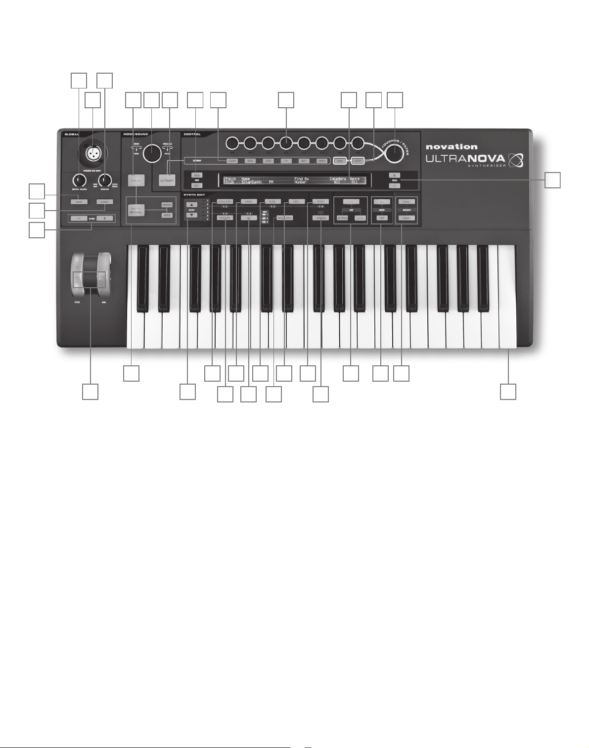
harDWare overvIeW
Top view - controls
[1] 37-note (3 octaves) keyboard with velocity and aftertouch sensing.
[2] PITCH and MOD wheels. The PITCH wheel is mechanically biased to return to the
centre position when released.
[3] 2-row x 72-character LCD dot matrix display. For most menus, the display is divided
into eight zones from left to right, with each zone corresponding to one of the rotary
encoders [5 ].
CONTROL sec tion
[4] PAGE BACK and NEXT buttons: these are used to step forwards and backwards
between menu pages. They illuminate to indicate that additional pages are available.
They have no function if the current menu only has one page.
[5] Rotary encoders – 8 touch-sensitive, detented rotary controls for parameter
selection. Touching each control selects a parameter for adjustment, the parameters
being indicated in the upper row of the LCD display [3] immediately below it.
Multiple parameters may be be selected for simultaneous adjustment if wished. (Use
of a rotary encoder in the manual text is indicated by ‘REn’, where n is the number of
the encoder; e.g. ‘RE1’ refers to rotary encoder 1). The touch sensitivity of the
conductive knobs is also used to make them active touch controllers, and envelope
re-triggering and other effects can be performed by simply touching the knobs.
[6] VALUE + and – buttons: These adjust the value of the currently-selected parameter
– as indicated by the LED below the encoder in use – either up or down. The
parameter value is indicated in the lower row of the LCD display.
[7] Automap controls: the LEARN, VIEW, USER, FX, INST and MIXER buttons are
used, in conjunction with the rotary encoders, with Novation’s Automap software
(see [26]).
[8] LOCK and FILTER buttons: these operate in conjunction with the
TOUCHED/FILTER knob [9]. FILTER assigns the knob to control the cut-off
frequency of Filter 1; LOCK fixes the function of the knob to the last touched
parameter.
[9] TOUCHED/FILTER: this is a large, touch-sensitive, “smooth-action” control
intended to aid more expressive performance when playing live. It either duplicates
the action of the last-touched rotary encoder, or, if the FILTER button [8] has been
pressed, Filter 1’s frequency.
SYNTH EDIT section
The buttons in the Synth Edit area of the control panel are laid out in logical order of sound
generation and treatment.
[10] SELECT K and J buttons: several of the main synth blocks are duplicated: there
are 3 oscillators, 6 envelope generators, 5 FX blocks, 3 LFOs and 2 filters. Each
block has its own menu, and the SELECT buttons let you select which block is to
be controlled. The 1 to 6 LEDs alongside indicate the block currently selected.
[11] OSCILLATOR button: opens an Oscillator Menu (two pages). The UltraNova has
3 oscillators, and the oscillator to be controlled can be chosen with the SELEC T K
and J buttons.
[12] MIXE R button: opens the Mixer Menu (two pages).
[13] FILTER button: opens a Filter Menu (two pages). The UltraNova has 2 filters, each
with its own menu. The filter to be controlled is selected with the SELECT K and J
buttons.
[14] VOICE button: opens the Voice Menu (one page).
[15] ENVELOPE button; opens an Envelope Menu ( two pages). The UltraNova has 6
envelope generators, each with its own menu. The envelope generator to be
controlled is selected with the SELECT K and J buttons.
[16] LFO button: opens an LFO Menu (two pages). The UltraNova has 3 LFOs (low
frequency oscillators), each with its own menu. The LFO to be controlled is selected
with the SELECT K and J buttons. The set of 3 dedicated LEDs adjacent to the
LFO button blink to indicate the current frequency of each LFO.
[17] MODULATION button: opens the Modulation Menu (one page).
[18] EFFECT button: opens an Effects (FX) Menu (four pages). The UltraNova has 5 FX
sections and the section to be controlled can be chosen with the Select K and J
buttons.
[19] VOCODER button: opens the Vocoder Menu (one page). An LED illuminates when
the Vocoder is active.
[20] ARP controls: the ON, SETTINGS and LATCH buttons control the UltraNova’s
Arpeggiator functions. The Arp Menu (one page) is displayed by pressing the
SETTINGS button, the ON button enables/disables the arpeggiator and the
1
2
3
4 5
6
7
8
9
10
15
16
17
18
21 22
23
24
25
26
27
2829
30
31
32
11 12 13 14
20
19
5
LATCH button applies the arpeggiator effect to the last note(s) played continuously,
until a subsequent key is pressed. LATCH can be pre-selected so that it is effective
as soon as the Arpeggiator is enabled.
[21] CHORD controls: the UltraNova lets you play a chord with a single keyboard note.
The ON button enables the Chorder function; the EDIT button opens the Chord
Edit Menu, from where chord definition and transposition can be performed.
[22] Animate controls: the TWE AK and TOUCH buttons enable alternative modes of
the eight rotar y encoders, allowing them to be used dynamically in performance.
TWE AK lets you set up a custom “control panel” of sound parameters for each
patch that you use, so that you can readily access those most needed; TOUCH
activates the encoders’ touch sensitivity, letting you introduce pre-programmed
alterations to your sound just by touching a knob.
MODE /SOUND controls
[23] Patch controls : the PATCH BROWSE button, together with the COMPARE and
WRITE buttons, lets you audition the UltraNova’s stored patches, compare them
with the current synth settings (par ticularly useful when modifying sounds) and
overwrite the patch with the current settings if wished.
[24] PATCH SELECT/SPEED DIAL rotary control: used in patch selection. Note that
this control has a push as well as a rotary function.
[25] SYNTH BUTTON: this puts the UltraNova into Synth mode, enabling the internal
sound generation and sound card functions.
[26] AUTOMAP BUTTON: Automap mode is the alternative to Synth mode, and
effectively disables the synthesizer control functions, allowing the UltraNova to act
as an Automap controller for plug-ins and DAWs. Use of this function requires
Novation’s Automap software package. Note that the synthesiser will still output
audio when triggered by MIDI from your DAW software.
GLOBAL controls
[27] Dynamic Mic Input : an XLR socket for the connection of the supplied gooseneck
microphone, or alternative dynamic microphone (i.e. a mic not requiring phantom
power to operate). The mic signal can be routed to the vocoder, mixed internally with
the synth and routed to the audio outputs. Additionally the mic input may be routed
directly to the DAW using the internal sound card. This input is overridden when a
jack plug is plugged in to Input 1 [11] on the rear panel.
[28] MONITOR : this rotary control adjusts the balance between audio from the Host
(PC or Mac, if connected) and the combined audio from the synth and audio inputs.
[29] MASTER VOLUME: the level control for the main audio outputs (and also for the
headphone output if the default setting for headphone level control in the Audio
Menu is retained.)
[30 ] AUDIO BUT TON : opens the Audio Menu (seven pages), allowing audio routing
and level adjustments to be made.
[31] GLOBAL BUTTON: opens the Global Menu (seven pages).
[32] OCTAVE + and – buttons: these two buttons transpose the keyboard up or down
one octave each time they are pressed, to a maximum of five octaves down or four
octaves up. When both LEDs are off (the default state), the lowest note on the
keyboard is one octave
Middle C
1
2 3
4
5
6
7
8
9
10
11
12
13
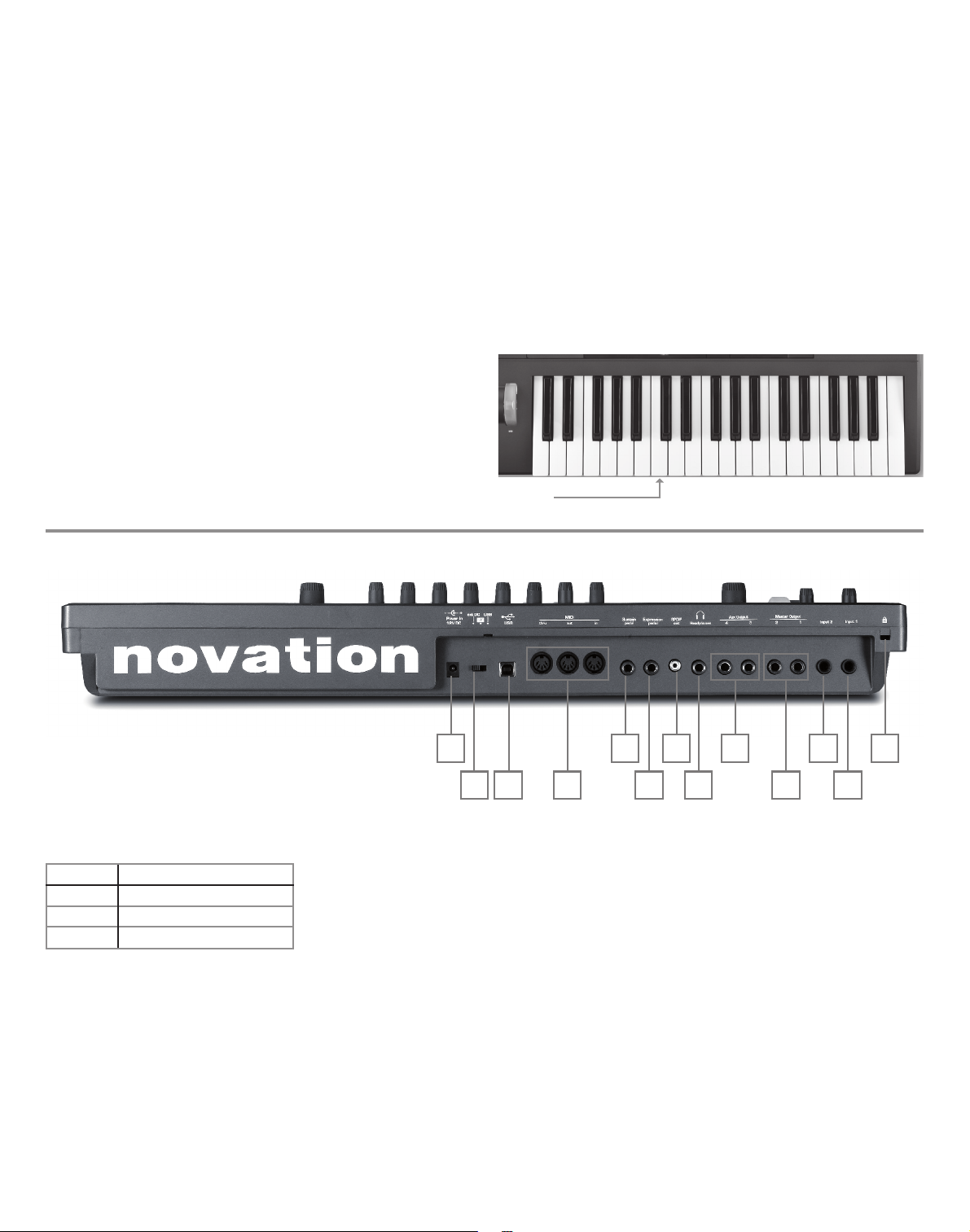
Rear view – connections
{1} DC power connector: standard 2.2 mm socket for connecting the external 12 V
DC PSU (supplied). See page 3.
{2} On/off switch: 3-position switch:
POSITION ACTION
Left Enables external 12 V DC input [1]
Centre Off
Right Enables power via USB port [3]
{3} USB port : Type B USB 1.1 (USB 2.0-compatible) socket for connection to PC or
Mac
{4} MIDI connectors: standard MIDI In/Out/Thru sockets (5-pin DINs)
{5} Sustain pedal socket: 2-pole (mono) ¼” jack socket for connection of a sustain
pedal. Both NO and NC pedal types are compatible; if the pedal is connected
when the UltraNova is powered on, the type will be automatically sensed during
boot-up (provided your foot is not on the pedal! ).
{6} Expression pedal socket: 3-pole (stereo) ¼” jack socket for connection of an
expression pedal. A full list of supported pedals can be found on the Novation
answerbase at w ww.novationmusic.com /answerbase
{7} SPDIF output: phono socket (RCA jack) carrying digital version of main outputs
1 & 2 in S-PDIF format.
{8} Headphone socket: 3-pole ¼” jack socket for stereo headphones. Phones volume
and mix can be adjusted independently from the Audio menu.
{9} Aux Outputs 3 & 4: 2 x ¼” jack sockets. Outputs are unbalanced, at +6 dBu
maximum level.
{10} Main outputs 1 & 2 : 2 x ¼” jack sockets carrying main stereo output. Outputs are
unbalanced, at +6 dBu maximum level.
{11} Input 2 : ¼” jack socket for ex ternal mic or line level audio inputs. The signal at Input
2 may be mixed internally with Input 1 using the Audio Menu. Inputs are balanced,
and can accept a maximum input level of +2 dBu.
{12} Input 1: ¼” jack socket for external mic or line level audio inputs. This input
overrides an XLR connector plugged into the Dynamic Mic Input [27] on the top
panel. Inputs are balanced, and can accept a maximum input level of +2 dBu.
{13} Kensington Lock Port : to secure your synthesizer.
6
gettIng StarteD
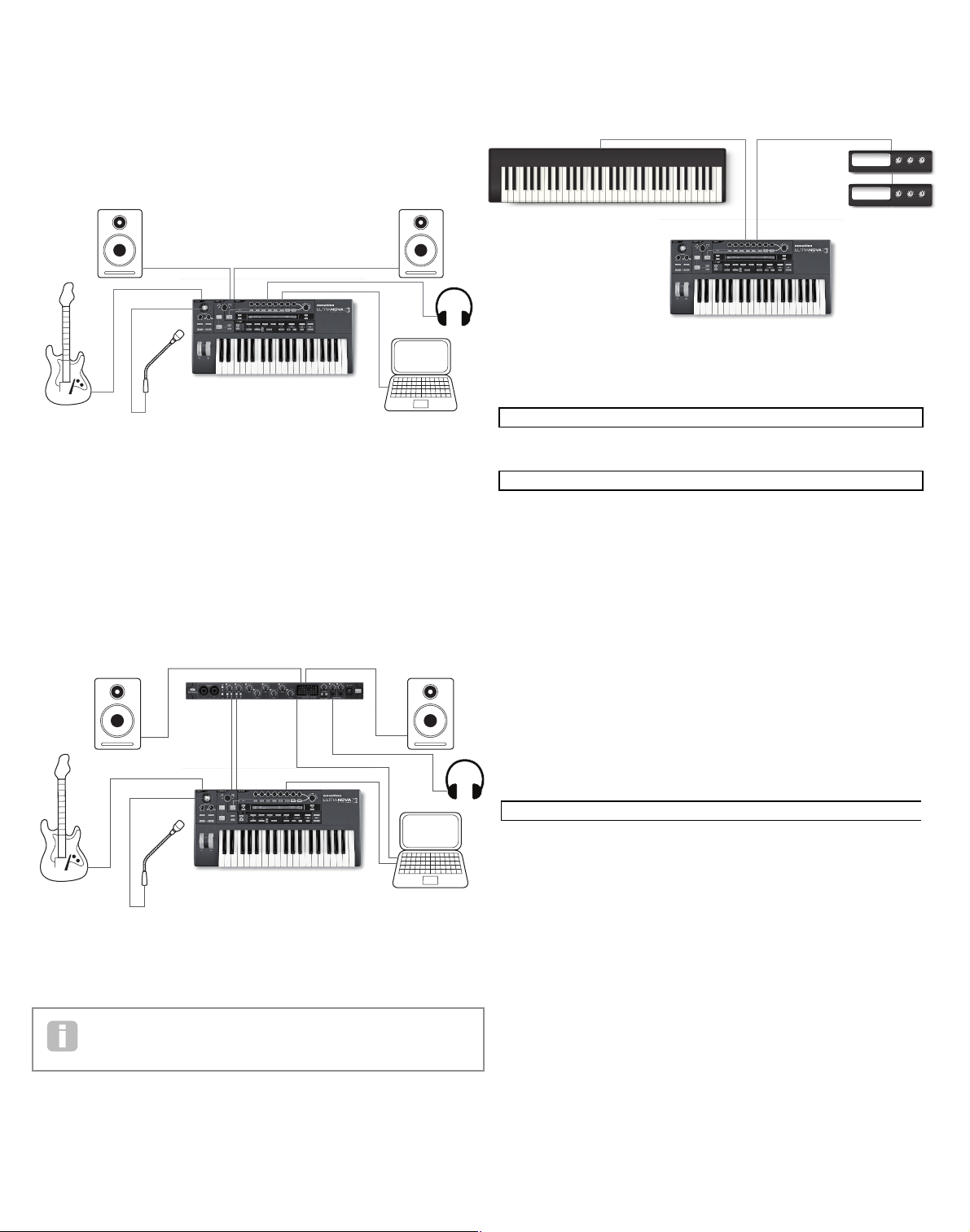
Standalone and computer operation – a foreword
The UltraNova may be used as a standalone synthesizer, with or without MIDI connections
to/from other sound modules or keyboards. It may also be connected - via its USB port - to
a computer (Windows or Mac) running a DAW application. The UltraNova can then be
controlled entirely from the computer by using the UltraNova Editor plug-in. The UltraNova
Librarian is a separate software application which greatly assists in the organising, saving
and recall of patches.
The methods of connecting the UltraNova to accommodate the various methods of working
are covered in the documentation supplied with the UltraNova Editor and UltraNova Librarian software packages. The Installers for this software, and the related USB drivers may be
downloaded from
http://novationmusic.com/support /ultranova.
Standalone operation – audio and MIDI connections
The simplest and quickest way of getting started with the UltraNova is to connect the two
rear panel jack sockets marked Master Output 1 and 2 {10} to the inputs of a stereo
amplifi er, audio mixer, powered speakers, third-party computer sound card or other means
of monitoring the output.
If using the UltraNova with other sound modules, connect MIDI OUT {4} on the UltraNova
to MIDI IN on the fi rst sound module, and daisy-chain further modules in the usual way. If
using the UltraNova with a master keyboard, connect the controller’s MIDI OUT to MIDI
IN on the UltraNova, and ensure that the master keyboard is set to MIDI channel 1 (the
UltraNova’s default channel).
With the amplifi er or mixer off or muted, connect the AC adaptor to the UltraNova {1}, and
plug it into the AC mains. Turn the UltraNova on by moving the rear panel switch {2} to E xt
DC. During power-up the display shows the fi rmware version number for a few seconds:
after which the Patch Menu appears:
Turn on the mixer/amplifi er/powered speakers, and set the Monitor Balance [28] to 12
o’clock, and turn up the Master Volume control [29 ] until you have a healthy sound level
from the speakers when you play the keyboard.
Using headphones
Instead of speakers via an amplifi er and /or an audio mixer, you may wish to use a pair of
stereo headphones. These may be plugged into the rear panel headphone output socket
{8}. The main outputs are still active when headphones are plugged in.
NOTE : The UltraNova headphone amplifi er is capable of outputting
a high signal level please take care when setting the output level.
The factory default setting for headphones’ level is for their volume to be controlled by the
Master Volume control. However, it is possible to set the headphones’ level independently;
although the Audio Menu is discussed in detail later in the manual, it may be useful to know
how to do this now. Press the AUDIO button [30] to open the Audio Menu, then press the
PAGE NEXT button [4] to access the Headphone Page:
Turning RE1 anticlockwise changes the Headphone Level Control setting to Us e Level
and Balan ce 1+2/3 +4. Then the headphone level can be adjusted independently of
the main outputs with RE6 (and any balance between synth sounds and inputs with RE7).
A word about Menu Navigation
The UltraNova has been designed to give the player maximum control over sound character
and system operation with the minimum of hassle. All the main menus are selected by a
single press on a dedicated button; for example, pressing the OSCILLATOR button will
always open the Oscillator Menu regardless of whereabouts in the menu system you might
currently be. There is no need to “back up” or “Exit” any menu, you can always go directly
from one menu to another with a single button press.
Several of the synth processing blocks - such as the Oscillator and Envelope Menus – are
duplicated; for example, there are 3 separate oscillators, each with its own menu. When
you re-select a menu for such a multiple block, it will open at the one you last used. For
example, if you adjust parameters of Envelope 4, then go to another menu to adjust some
other parameters, and then press the ENVELOPE button again, the Envelope Menu will
re-open with the parameters for Envelope 4 visible. The same principle applies to menus
which have multiple pages – UltraNova remembers which parameters you were last adjusting, and re-opens the menu at the last-used page.
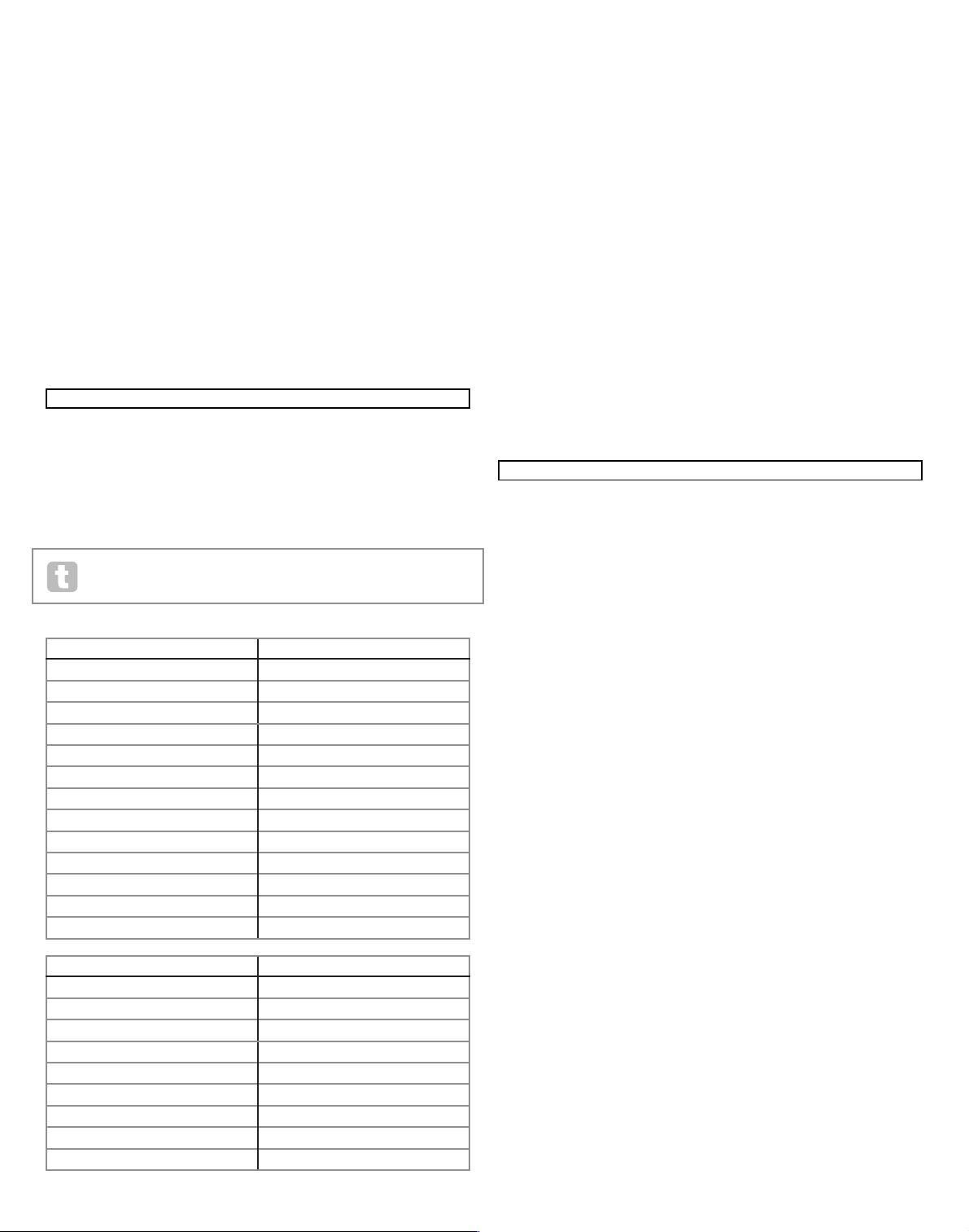
Audio In
Audio Out
USB
UltraNova connected to a computer via USB.
USB transmits audio and MIDI to and from the computer
Audio In
Audio Out
USB
FireWire/USB
UltraNova connected to computer soundcard
via analogue audio outs.
USB transmits MIDI to and from computer
MIDI In
Controller Keyboard
MIDI Out
Sound Modules
Novation UltraNova
Version 1.0.00
Novation UltraNova
Version 1.0.00
Patch Name
A000
Circuit Motion
COMPRES1 C1Ratio C1Thrsh C1Attack C1Rel C1Hold C1Gain
2.0 -20 0 64 32 127
DISTORT1 Dst1Type Dst1Comp Dst1Lvl
Diode 100 0
REVERB1 Rvb1Type Rvb1Dec
LrgHall 90
Off On 1 Off Set by Patch
TuneCent Transpse KbdVel VelResp DfltRate FootSwth Whlights
0 0 Curve 4 Medium 48KHz Auto On
ClockSource Clock} 120 BPM
Auto Status} Internal Clock
DUMP to Bank Patch Name Current OnePatch OneBank AllBanks
USBport A 0 Init Program
DUMP to ^^
USBport GLOBALS & AUDIO
Calibrate BendWhl ModWhl Aftouch SetAftouch
Current O/S Transmit ^^
Current O/S Version 1.0.00
Startup O/S Version 1.0.00
0dB
Indept Off Off In2 -60
0dB 0 0
HeadPhones Level Control Level Balance 1+2/3+4
Follow master volume (1+2 only) 127 0
Note: the UltraNova is not a computer MIDI interface. MIDI can be transmitted
between UltraNova synth and computer but MIDI cannot be transmitted to and
from the UltraNova MIDI DIN ports from the computer.
7
ScrollIng through
patcheS
Your UltraNova comes pre-loaded with a set of factor y patches, which may be auditioned
from the opening Patch Menu. The opening Patch Menu can always be accessed by pressing the SYNTH button [25]. The patches are arranged as 4 banks (A to D), each with 127
patches (000 to 126). Rotate RE1 to scroll through the patches. The new sound is loaded
as soon as the patch data shows in the display. Alternatively, the PATCH/BANK knob [24]
can be used to dial through the whole set; in this case, rotate the PATCH/BANK knob to
select the patch and push and rotate the knob select the bank. Note that the name of the
patch is also displayed.
SearchIng through
categorIeS
Apart from being arranged in 4 banks, the patches are also categorised for you according
to the type of sound; this makes finding suitable sounds much easier. Each patch belongs
to both a Genre and a Categor y; the Genre broadly indicates the musical area for which
the patch might be suitable, the Category further subdivides the set by sonic characteristics. Press the PATCH BROWSE button [23 ], and the display below appears:
The display shows the location and name of the currently-selected patch. The default is for
all patches to be available, because the Genre and Category search criteria are both set
to ‘All’. RE8 and RE7 let you reduce the number of available patches by filtering only those
which belong to a selected Genre and/or Category respectively.
Once the filter criteria have been set, the reduced patch set can be browsed either in location order (the default), or by name, alphanumerically. This choice is set by RE5, which sets
the ‘Find By’ parameter to either ‘A000-D127’ (location order) or ‘A-Z’ (alpha sort).
If there are no matches for the Genre/Category combination selected you will not
be able to change the patch – try a dif ferent combination!
The Genres and Categories are listed below:
CATEGORY DISPLAY SHOWS:
Bass
Bass
Bell
Bell
Classic
Classic
Drum
Drum
Keyboard
Keyb oard
Lead
Lead
Movement
Move ment
Pad
Pad
Poly
Poly
SFX
SFX
String
String
External Input
ExtInput
Vocoder
Voco der
GENRE DISPLAY SHOWS:
Classic
Classic
Drum ‘n’ Bass/ Breaks
D&B/ Brks
House
Hous e
Industrial
Industri
Jazz
Jazz
R ‘n’ B/ Hip Hop
R&B/ HHop
Rock and Pop
Rock/Po p
Techno
Techno
Dubstep
Dubst ep
comparIng patcheS
When editing stored patches to create new sounds it may be useful to compare the edited
version with the original stored patch. This is achieved by using the COMPARE [23]
button. Press the COMPARE button and play a key, and you will hear the original stored
patch. Release the COMPARE button play the key again and you will hear the patch in its
currently edited state. If you press the COMPAR E button while in any of the menu pages
(except the Write menu), the stored patch parameters will be displayed.
You can compare the currently edited patch with any preset stored in the UltraNova. This
is useful when selecting a new location for the patch to be saved to. To do this, press the
WRITE [23] button twice to access page 2 of the Write menu. Using RE2 (Bank) and
RE3 (Patch) select the stored patch that you want to compare. Pressing and holding the
COMPARE button and a key will enable the stored patch to sound.
Note: If the WRITE button is pressed again (while in page 2 of the Write menu ), the currently edited patch will be saved in the location selected by RE2 and RE3. To avoid saving
the edited patch press any other synth button to exit the Write menu (e.g., SYNTH [25]).
StorIng a patch
It is possible to store or write your own patches directly into the UltraNova without using
the UltraNova Librarian sof tware application. The Write menu consists of two pages and
both can be accessed by pressing the WR ITE [23] button. A third press of the WRITE
button will store the preset. It is also possible to move between the pages using the PAGE
BACK and NEXT buttons [4].
Entering patch name (Page 1)
RE1: Not used.
RE2 : Cursor Position
This moves the cursor position up and down the text string for the purpose of editing
characters.
RE3 : Charac ter select
Turning RE3 scrolls through the entire character set (A-Z, a-z, 0-9 and special characters).
The location of the character being edited is determined by RE2.
RE4 : not used
RE5: Uppercase characters
The parameter scrolls through the uppercase character set ‘A’ to ‘Z’. The location of the
character being edited is determined by RE2. Press the flashing button directly below RE5
to enter the character and automatically increment the cursor to its next position.
RE6 : Lowercase characters
The parameter scrolls through the lowercase character set ‘a’ to ‘z’. The location of the
character being edited is determined by RE2. Press the flashing button directly below RE6
to enter the character and automatically increment the cursor to its next position.
RE7: Numerical characters
The parameter scrolls through the numerical character set ‘0’ to ‘9’. The location of the
character being edited is determined by RE2. Press the flashing button directly below RE7
to enter the character and automatically increment the cursor to its next position.
RE8: Punctuation and special charac ters
The parameter scrolls through a set of punctuation and special characters. The location of
the character being edited is determined by RE2. Press the flashing button directly below
RE8 to enter the character and automatically increment the cursor to its next position.
0 0 0 64 64 64
DELAY1 Dly1Time Dly1Sync Dly1Fbck Dly1L/R Dly1Wdth DLy1Slew
64 Off 64 1/1 127 127
CHORUS1 Ch1Type Ch1Rate Ch1Sync Ch1Fbck Ch1Depth Ch1Delay
Chorus 20 Off +10 64 64
GATOR GtOn/Off GtLatch GtRSync GtKSync GtSlew GtDecay GtL/Rdel
On Off 16th On 16 64 0
GATOR GtMode EditGroup EEEE---- --------
Mono16 1 -------- --------
A000 Init Program
Patch Name Find By Category Genre
A000 Init Program A000-D127 All All
PATCHSAVE Posng *------- -------- Upper Lower Number Punctuate
A o Init Program A a 0 space
8
Saving a patch (Page 2)
RE1: Not used.
RE2 : Bank selection
Use this control to select which bank (A ,B,C or D) the patch is to be written to.
RE3 : Patch position
Use this control to select the patch destination number where the currently edited sound
will be written to. The current destination patch name will be displayed under RE4 and
RE5 for reference, although this will be overwritten with the new patch name if the patch is
saved without changing the position.
Use the COMPARE button to listen to the patch selected by RE2 and RE3.
RE4 – RE5: Not used.
RE6 : Category select
Select a category for the new patch. See page 7 for the list of categories.
RE7: Genre select
Select a genre for the new patch. See page 7 for the list of available genres.
RE8: Not used.
To exit the Write menu press any other synth button (e.g., SYNTH [25]).
Note: A faster method of managing patches (writing, loading, renaming, reordering etc. ) is
by using the downloadable UltraNova Librarian. This can be downloaded free of charge from
http://novationmusic.com/support /ultranova.
Updating the UltraNova’s Operating System (PC)
OS update files will be available from time to time at
www.novationmusic.com/support/ultranova in the form of a MIDI SysE x file. The update
procedure requires the UltraNova to be connected via USB to a computer which has first
had the necessary USB drivers installed. Full instructions on performing the update will be
supplied with the download.
SyntheSIS tutorIal
This section covers the subject of sound generation in more detail and discusses the various basic features available in the UltraNova’s sound generation and processing blocks.
It is recommended that this chapter is read carefully if analogue sound synthesis is an
unfamiliar subject. Users familiar with this subject can skip this chapter and move on to the
next chapter.
To gain an understanding of how a synthesizer generates sound it is helpful to have an appreciation of the components that make up a sound, both musical and non-musical.
The only way that a sound may be detected is by air vibrating the eardrum in a regular,
periodic manner. The brain interprets these vibrations (very accurately) into one of an
infinite number of different types of sound.
Remarkably, any sound may be described in terms of just three properties, and all sounds
always have them. They are:
• Pitch
• Tone
• Volume
What makes one sound different from another is the relative magnitudes of the three
properties as initially present in the sound, and how the properties change over the
duration of the sound.
With a musical synthesizer, we deliberately set out to have precise control over these three
properties and, in particular, how they can be changed during the “lifetime” of the sound.
The properties are often given different names: Volume may be referred to as Amplitude,
Loudness or Level, Pitch as Frequency and Tone as Timbre.
Pitch
As stated, sound is perceived by air vibrating the ear drum. The pitch of the sound is
determined by how fast the vibrations are. For an adult human, the slowest vibration
perceived as sound is about twenty times a second, which the brain interprets as a bass
type sound; the fastest is many thousands of times a second, which the brain interprets as
an high treble type sound.
If the number of peaks in the two waveforms (vibrations) are counted, it will be seen that
there are exactly twice as many peaks in Wave B as in Wave A. (Wave B is actually an
octave higher in pitch than Wave A). It is the number of vibrations in a given period that
determines the pitch of a sound. This is the reason that pitch is sometimes referred to as
frequency. It is the number of waveform peaks counted during a given period of time which
defines the pitch, or frequency.
Tone
Musical sounds consist of several different, related pitches occurring simultaneously. The
loudest is referred to as the ‘fundamental’ pitch and corresponds to the perceived note
of the sound. Other pitches making up the sound which are related to the fundamental in
simple mathematical ratios are called harmonics. The relative loudness of each harmonic
as compared to the loudness of the fundamental determines the overall tone or ‘timbre’ of
the sound.
Consider two instruments such as a harpsichord and a piano playing the same note on the
keyboard and at equal volume. Despite having the same volume and pitch, the instruments
still sound distinctly different. This is because the different note-making mechanisms of
the two instruments generate different sets of harmonics; the harmonics present in a piano
sound are different to those found in a harpsichord sound.
Time Time
A B
0 0 0 64 64 64
DELAY1 Dly1Time Dly1Sync Dly1Fbck Dly1L/R Dly1Wdth DLy1Slew
64 Off 64 1/1 127 127
CHORUS1 Ch1Type Ch1Rate Ch1Sync Ch1Fbck Ch1Depth Ch1Delay
Chorus 20 Off +10 64 64
GATOR GtOn/Off GtLatch GtRSync GtKSync GtSlew GtDecay GtL/Rdel
On Off 16th On 16 64 0
GATOR GtMode EditGroup EEEE---- --------
Mono16 1 -------- --------
A000 Init Program
Patch Name Find By Category Genre
A000 Init Program A000-D127 All All
PATCHSAVE Posng *------- -------- Upper Lower Number Punctuate
A o Init Program A a 0 space
PATCHSAVE Bank Patch Destination SaveCatg SaveGenre
Dest+C&G A 0 Init Program None None
9
Volume
Volume, which is often referred to as the amplitude or loudness of the sound is determined
by how large the vibrations are. Very simply, listening to a piano from a metre away would
sound louder than if it were fifty metres away.
Having shown that just three elements may define any sound, these elements now have to
be related to a Musical synthesizer. It is logical that a dif ferent section of the Synthesizer
‘synthesizes’ (or creates) these different elements.
One section of the synthesizer, the Oscillators, provide raw waveform signals which
define the pitch of the sound along with its raw harmonic content (tone). These signals
are then mixed together in a section called the Mixer, and the resulting mixture is then fed
into a section called the Filter. This makes further alterations to the tone of the sound, by
removing (filtering) or enhancing certain of the harmonics. Lastly, the filtered signal is fed
into the Amplifier, which determines the final volume of the sound.
Additional synthesizer sections - LFOs and Envelopes - provide further ways of altering
the pitch, tone and volume of a sound by interacting with the Oscillators, Filter and
Amplifier, providing changes in the character of the sound which can evolve over time.
Because LFOs’ and Envelopes’ only purpose is to control (modulate) the other
synthesizer sections, they are commonly known as ‘modulators’.
These various synthesizer sections will now be covered in more detail.
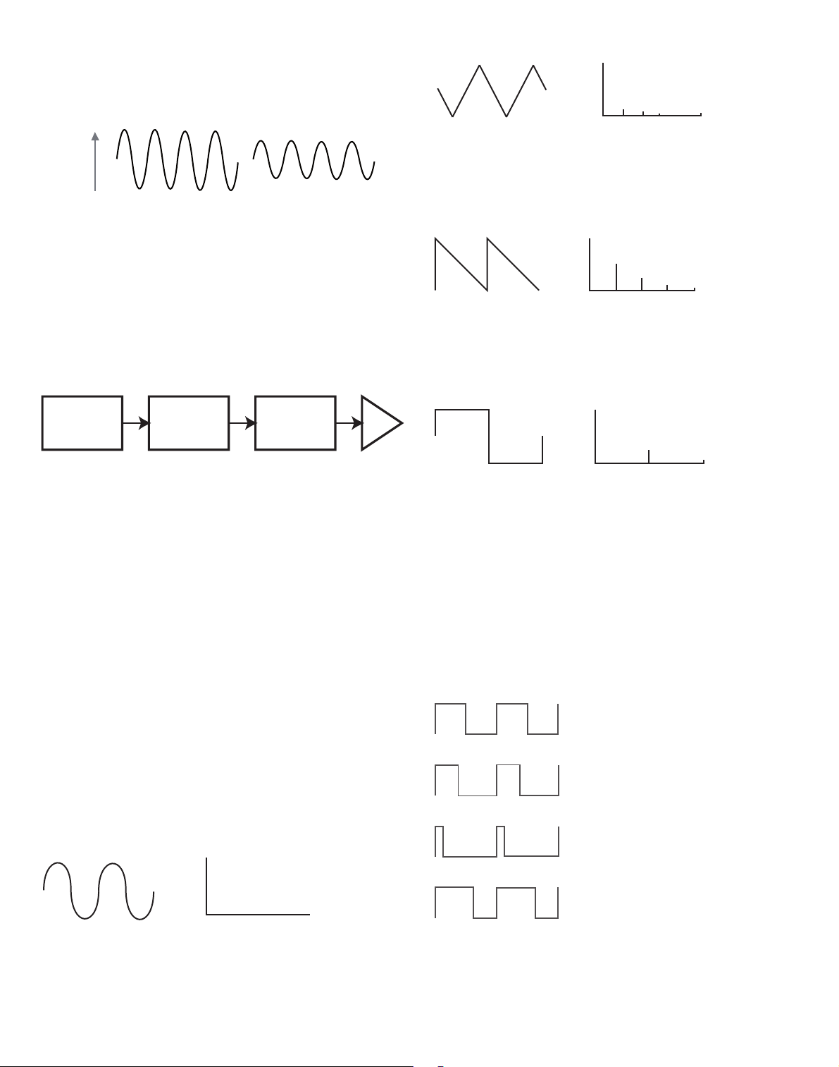
The Oscillators And Mixer
The Oscillator is really the heartbeat of the Synthesizer. It generates an electronic wave
(which creates the vibrations when eventually fed to a loudspeaker). This Waveform is
produced at a controllable musical pitch, initially determined by the note played on the keyboard or contained in a received MIDI note message. The initial distinctive tone or timbre of
the waveform is actually determined by the waveform’s shape.
Many years ago, pioneers of musical synthesis discovered that just a few distinctive
waveforms contained many of the most useful harmonics for making musical sounds. The
names of these waves reflect their actual shape when viewed on an instrument called an
Oscilloscope, and these are: Sine waves, Square waves, Sawtooth waves, Triangle waves
and Noise.
Each waveform shape (except noise) has a specific set of musically-related harmonics
which can be manipulated by further sections of the synthesizer.
The diagrams below show how these waveforms look on an oscilloscope, and illustrate the
relative levels of their harmonics. Remember, it is the relative levels of the various harmonics present in a waveform which determine the tone of the final sound.
Sine Waves
These possess just a single harmonic. A sine waveform produces the “purest” sound
because it only has its single pitch (frequency).
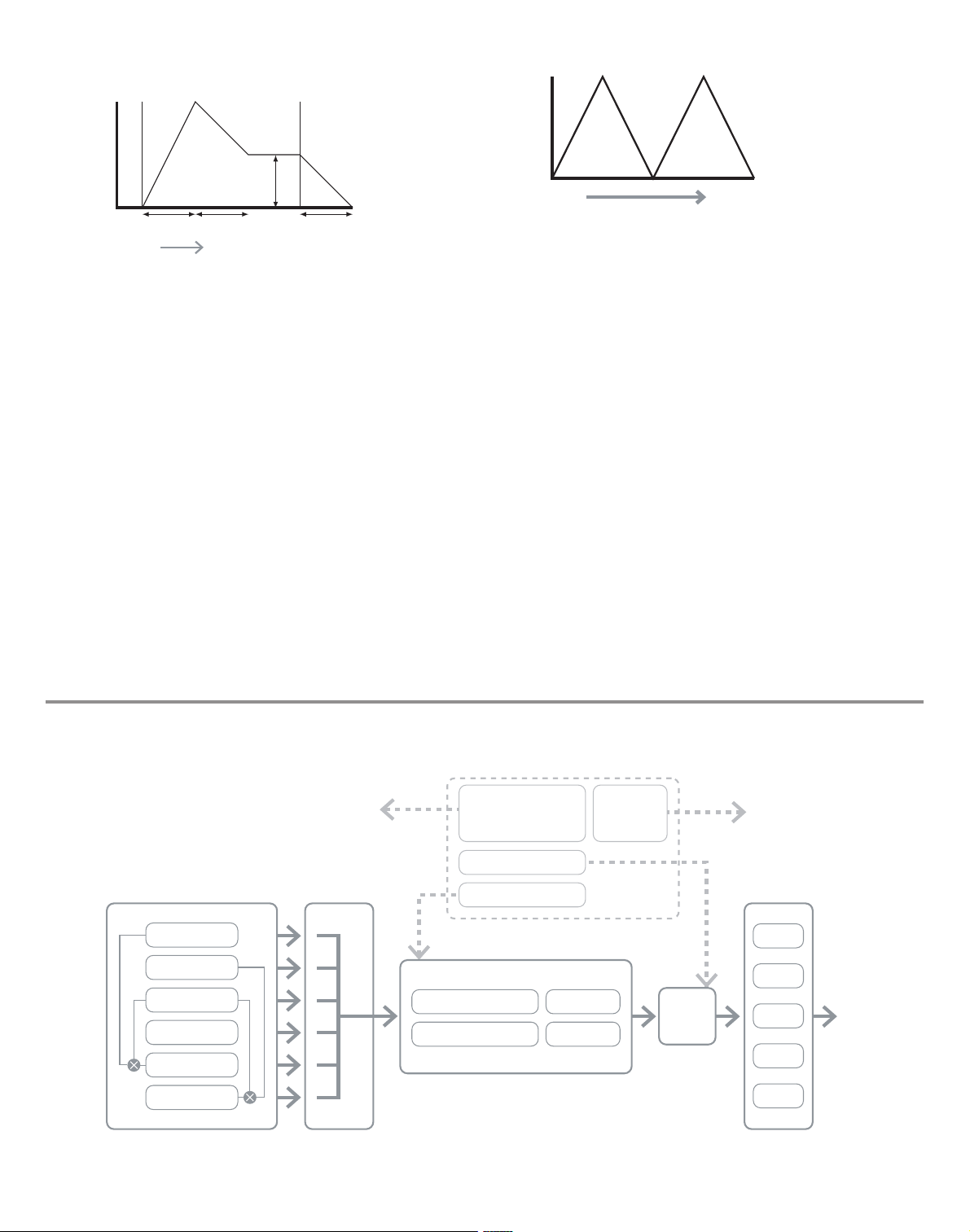
Triangle Waves
These contain only odd harmonics. The volume of each decreases as the square of its
position in the harmonic series. For example, the 5th harmonic has a volume 1/25th of the
volume of the fundamental.
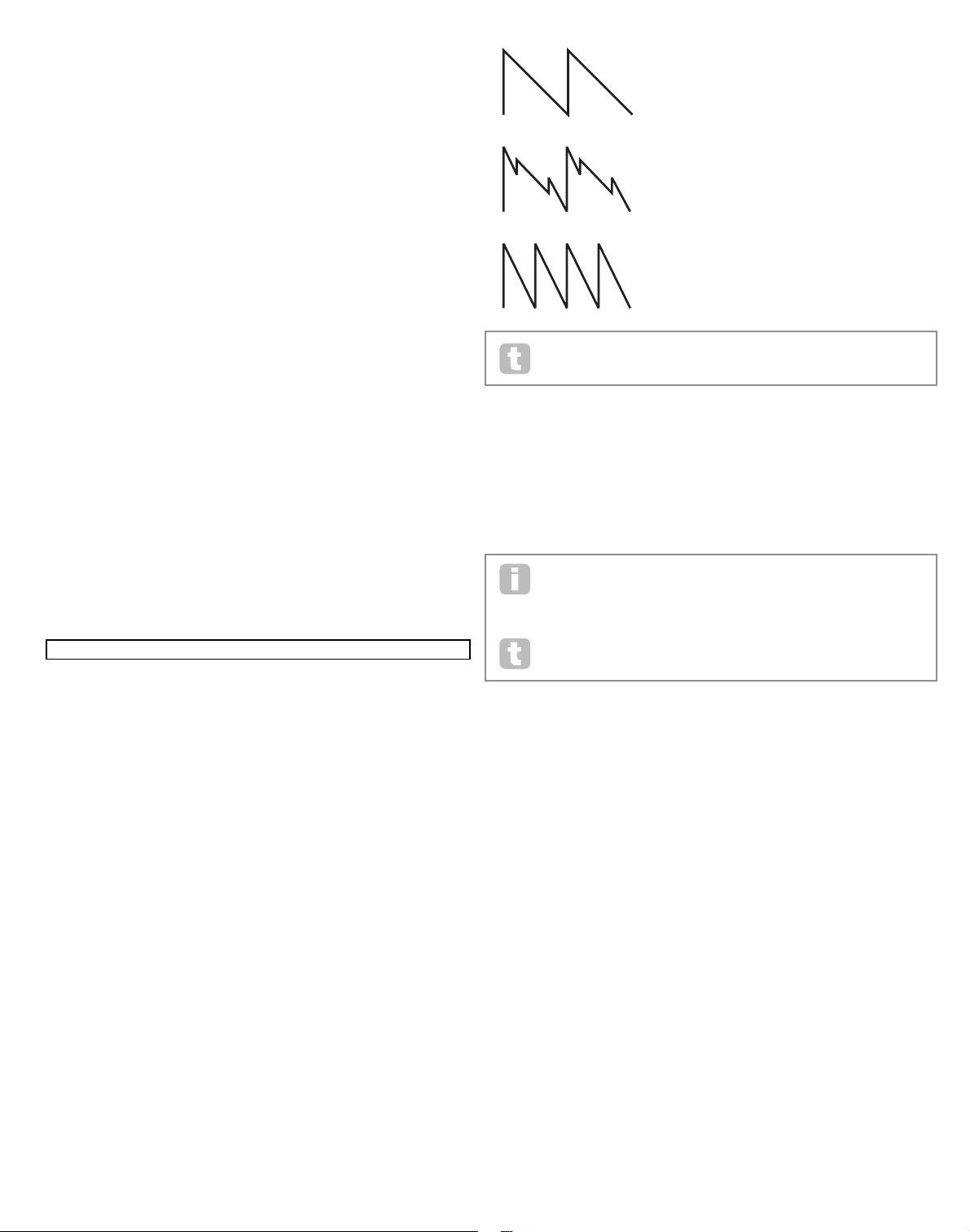
Sawtooth Waves
These are rich in harmonics, and containing both even and odd harmonics of the fundamental frequency. The volume of each is inversely proportional to its position in the
harmonic series.
Square / Pulse Waves
These only have odd harmonics, which are at the same volume as the odd harmonics in a
sawtooth wave.
It will be noticed that the square waveform spends equal amounts of time in its ‘high’ state
and its ‘low’ state. This ratio is known as the ‘duty cycle’. A square wave always has a duty
cycle of 50% which means it is ‘high’ for half the cycle and ‘low’ for the other half.
In the Ultranova, it is possible to adjust the duty cycle of the basic square waveform to
produce a waveform which is more ‘rectangular’ in shape. These are often known as Pulse
waveforms. As the waveform becomes more and more rectangular, more even harmonics
are introduced and the waveform changes its character, becoming more ‘nasal’ sounding.
The width of the pulse waveform (the ‘Pulse Width’) can be altered dynamically by a modulator, which results in the harmonic content of the waveform constantly changing. This can
give the waveform a very ‘fat’ quality when the pulse width is altered at a moderate rate.
It does not make any difference to how a
pulse waveform sounds whether the duty
cycle is 40% or 60% , since the waveform is
just “inverted” and the harmonic content is
exactly the same.
Volume
A B
Oscillators Mixer Filter Amplifier
Volume
Harmonic
1
Sine Wave
Volume
Harmonic
1 3 5 7
Triangle Wave
Sawtooth Wave
Volume
Harmonic
1 2 3 4 5
Square Wave
Volume
Harmonic
1 2 3 4 5
50%
40%
10%
60%
10
Noise Waves
Volume
1 2 3 4 5
These are basically random signals, and have no one fundamental frequency (and therefore
no pitch proper ty). All frequencies are at the same volume. Because they possess no pitch,
noise signals are often useful for creating sound effects and percussion type sounds.
Digital Waveforms
In addition to the traditional types of Oscillator waveforms detailed above, the UltraNova
also offers a set of carefully selected, digitally-generated waveforms containing useful
harmonic elements normally difficult to produce using traditional Oscillators.
Wavetables
A “wavetable” is essentially a group of digital waveforms. The UltraNova’s 36 wavetables
each contain 9 separate digital waveforms. The benefit of a wavetable is that consecutive
waveforms in the wavetable can be blended. Some of the UltraNova’s wavetables contain
waveforms with similar harmonic content, while others contain waveforms with greatly differing harmonic content. Wavetables come alive when the ‘wavetable index’ – the position
within the wavetable - is modulated, resulting in a sound that continually changes character,
either smoothly or abruptly.
9 Waves make up a wave table
Ring Modulation
A Ring Modulator is a sound generator that takes signals from two of the UltraNova’s
osclillators and effectively “multiplies” them together. The Ultranova has 2 Ring Modulators,
one takes Osc 1 and Osc 3 as inputs, and the other takes Osc 2 and Osc 3. The resulting
output depends on the various frequencies and harmonic content present in each of the
two oscillator signals, and will consist of a series of sum and difference frequencies as well
as the frequencies present in the original signals.
The Mixer
To extend the range of sounds that may be produced, typical analogue synthesizers have
more than one Oscillator. By using multiple Oscillators to create a sound, it is possible
to achieve very interesting harmonic mixes. It is also possible to slightly detune individual
Oscillators against each other, which creates a very warm, ‘fat’ sound. The UltraNova’s
Mixer allows mixing of three independent Oscillators, a separate Noise Oscillator and two
Ring Modulator sources.
The Filter
The Ultranova is a subtractive music synthesizer. Subtractive implies that part of the sound
is subtracted somewhere in the synthesis process.
The Oscillators provide the raw waveforms with plenty of harmonic content and the Filter
section subtracts some of the harmonics in a controlled manner.
14 types of Filter are available on the UltraNova, though these are varieties of three basic
filter types: Low Pass, Band Pass and High Pass. The type of Filter most commonly found
on synthesizers is the Low Pass type. With a Low Pass Filter, a cut-off point (or cut-off frequency) is chosen and any frequencies below the point are passed, and frequencies above
are filtered out. The setting of the Filter Frequency parameter dictates the point below
which frequencies are removed. This process of removing harmonics from the waveforms
has the effect of changing the sound’s character or timbre. When the Frequency parameter
is at maximum, the filter is completely “open” and no frequencies are removed from the raw
Oscillator waveforms.
In practice, there is a gradual (rather than a sudden) reduction in the volume of the
harmonics above the cut-off point of a Low Pass Filter. How rapidly these harmonics
reduce in volume as frequency increases above the cut-off point is determined by the
Filter’s slope. The slope is measured in ‘volume units per octave’. Since Volume is
measured in decibels, this slope is usually quoted as so many decibels per octave
(dB/oct). Typical values are 12 dB/oct and 24 dB /oct. The higher the number, the greater
the rejection of harmonics above the cut-off point, and the more pronounced the filtering effect.
A further important parameter of the Filter is its Resonance. Frequencies at the cut-off point
may be increased in volume by the Filter Resonance control. This is useful for emphasizing
certain harmonics of the sound.
As Resonance is increased, a whistling-like quality will be introduced to the sound passing
through the filter. When set to very high levels, Resonance actually causes the filter to self
- oscillate whenever a signal is being passed through it. The resulting whistling tone being
produced is actually a pure sine wave, the pitch of which depends on the setting of the
Frequency knob (the filter’s cut-off point). This resonance-produced sine wave can actually
be used for some sounds as an additional sound source if wished.
The diagram below shows the response of a typical low pass filter. Frequencies above the
cut-off point are reduced in volume.
When resonance is added, frequencies at the cut off point are boosted in volume.
OSC 1
OSC 3
X
OSC 1
OSC 1 VOLUME
OSC 2 VOLUME
OSC 3 VOLUME
COMPLEX
WAVEFORM
MIX OF
OSC1, 2 AND 3
MIXE R
INPUT TO
FILTER
OSC 2
OSC 3
Volume
Frequency
Cutoff
Frequency
Volume
Frequency
Cutoff
Frequency

11
In addition to the traditional Low Pass Filter type, there are also High Pass and Band Pass
types. The type of Filter used is selected with the Filter Type parameter.
A High Pass Filter is similar to a Low Pass Filter, but works in the “opposite sense”, so that
frequencies below the cut-off point are removed. Frequencies above the cut-off point are
passed. When the Filter Frequency parameter is set to zero, the filter is completely open
and no frequencies are removed from the raw Oscillator waveforms.
Volume
Frequency
Cutoff
Frequency
When a Band Pass Filter is used, only a narrow band of frequencies centered around the
cut- off point are passed. Frequencies above and below the band are removed. It is not
possible to fully open this type of Filter, and allow all frequencies to pass.
Envelopes And Amplifier
In earlier paragraphs, the synthesis of the pitch and the timbre of a sound were described.
The next part of the Synthesis Tutorial describes how the volume of the sound is controlled.
The volume of a note created by a musical instrument often varies greatly over the duration
of the note, according to the type of instrument.
For example, a note played on an Organ quickly attains full volume when a key is pressed.
It stays at full volume until the key is released, at which point the volume level falls instantly
to zero.
A Piano note quickly attains full volume after a key is pressed, and gradually falls in volume
to zero after several seconds, even if the key is held.
A String Section emulation only attains full volume gradually when a key is pressed. It
remains at full volume while the key is held down, but once the key is released, the volume
falls zero fairly slowly.
In an analogue synthesizer, changes to a sound’s character which occur over the duration
of a note are controlled by a section called an Envelope Generator. The UltraNova has 6
Envelope Generators (called Env 1 to Env 6). Env 1 is always related to an Amplifier, which
controls the note’s amplitude – i.e., the volume of the sound - when the note is played.
Each envelope generator has four main controls which are used to adjust the shape of the
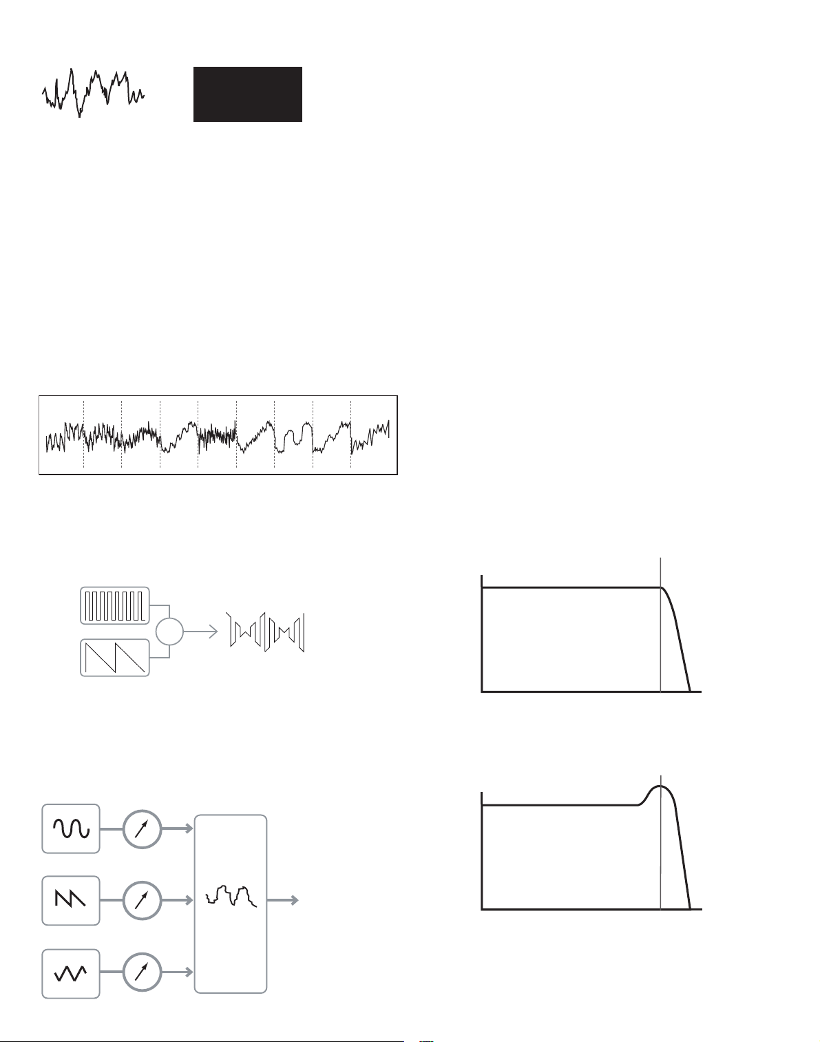
envelope.
Attack Time
Adjusts the time it takes after a key is pressed for the volume to climb from zero to full
volume. It can be used to create a sound with a slow fade-in.
Decay Time
Adjusts the time it takes for the volume to fall from its initial full volume to the level set by the
Sustain control while a key is held down.
Sustain Level
This is unlike the other Envelope controls in that it sets a level rather than a period of time.
It sets the volume level that the envelope remains at while the key is held down, af ter the
Decay Time has expired.
Release Time
Adjusts the time it takes for the volume to fall from the Sustain level to zero once the key is
released. It can be used to create sounds that have a “fade-out” quality.
A typical synthesizer will have one or more envelopes. One envelope is always applied to
the amplifier to shape the volume of each note played. Additional envelopes can be used to
dynamically alter other sections of the synthesizer during the lifetime of each note.
The UltraNova’s second Envelope Generator (Env 2) is used to modify the filter cut-off
frequency over the lifetime of a note.
Volume
Frequency
Cutoff
Frequency
TIME
KEY "ON" KEY "OFF"
VOLUME
TIME
KEY "ON" KEY "OFF"
VOLUME
TIME
KEY "ON" KEY "OFF"
VOLUME
ATTACK DECAY R ELEASE
SUSTAIN
KEY "ON" KEY "OFF"
VOLUME
12
In the UltraNova, Envelope Generators 3 to 6 can be used for special purposes, such as
Modulating the Wavetable index or FX levels.
LFOs
Like the Envelope Generators, the LFO section of a synthesizer is a Modulator. Thus instead of being a part of the sound synthesis itself, it is used to change (or modulate ) other
sections of the synthesizer. For example, an LFO can be used to alter Oscillator pitch, or
Filter cutoff frequency.
Most musical instruments produce sounds that vary over time both in volume and in pitch
and timbre. Sometimes these variations can be quite subtle, but still contribute greatly
towards characterising the final sound.
Whereas an Envelope is used to control a one-off modulation over during the lifetime of a
single note, LFOs modulate by using a repeating cyclic waveform or pattern. As discussed
earlier, Oscillators produce a constant waveform which can take the shape of a repeating
sine wave, triangle wave etc. LFOs produce waveforms in a similar way, but normally at a
frequency which is too low to produce a sound that the human ear could perceive. (In fact,
LFO stands for Low Frequency Oscillator.)
As with an Envelope, the waveforms generated by the LFOs may be fed to other parts of
the synthesizer to create the desired changes over time – or ‘movements’ - to the sound.
The UltraNova has three independent LFOs, which may be used to modulate different
synthesizer sections and can run at different speeds.
A typical waveshape for an LFO would be a Triangle wave.
Imagine this very low frequency wave being applied to an Oscillator’s pitch. The result is
that the pitch of the Oscillator slowly rises and falls above and below its original pitch. This
would simulate, for example, a violinist moving a finger up and down the string of the instrument whilst it is being bowed. This subtle up and down movement of pitch is referred to as
the ‘Vibrato’ effect.
Alternatively, if the same LFO signal were to modulate the Filter cut-off frequency instead of
the Oscillator pitch, a familiar wobbling effect known as ‘wah- wah’ would be result.
As well as setting up various sections of the synthesizer to be modulated by LFOs, additional Envelopes may also be used as modulators at the same time. Clearly, the more
Oscillators, Filters, Envelopes and LFOs there are in a synthesizer, the more powerful it is.
Summary
A synthesizer can be broken down into five main sound generating or sound modifying
(modulating) blocks.
1 Oscillators that generate waveforms at a various pitches.
2 A Mixer that mixes the outputs from the Oscillators together.
3 Filters that remove certain harmonics, changing the character or timbre of the sound.
4 An Amplifier controlled by an Envelope generator, which alters the volume of a sound
over time when a note is played.
5 LFOs and Envelopes that can be used to modulate any of the above.
Much of the enjoyment to be had with a Synthesizer is with experimenting with the factory
preset sounds and creating new ones. There is no substitute for ‘hands on‘ experience.
Experiments with adjusting the UltraNova’s many parameters will eventually lead to a fuller
understanding of how the various controls alter and help shape new sounds.
Armed with the knowledge in this chapter, and an understanding of what is actually happening in the machine when tweaks to the knobs and switches are made, the process of
creating new and exciting sounds will become easy - Have fun.
ATTACK DECAY R ELEASE
SUSTAIN
TIME
KEY "ON" KEY "OFF"
FILTER
CUT-OFF
TIME
PITCH
OSCILLATOR 1
FX 1
FX 2
FX 3
FX 4
FX 5
OSCILLATOR 2
OSCILLATOR 3
NOISE
AMP OUT
MIXE R
RING MOD 1*3
RING MOD 2*3
FILTER 1 DISTORTION
FILTER 2 DISTORTION
FILTER 1
FILTER 2
ENVELOPE 1
ENVELOPE 2
ENVELOPE S 3 - 6 LFO 1 - 3
ultranova SIgnal floW DIagram
13
Synth eDIt SectIon
Hardware Navigation
See page 4 for an overview of the UltraNova and a brief description of what each of the top
panel controls do.
On the UltraNova, all the menus which control the sound generation and sound processing
blocks are accessed by the buttons in the Synth Edit area of the top panel.
When a menu is called up, the parameter values displayed are those of the currentlyselected patch.
Each menu is accessed by its own dedicated button, and has between one and four pages.
If a menu has more than one page, one of the two PAGE buttons [4] will be illuminated,
and these can be used to scroll through the additional pages. Up to eight parameters of
the menu are displayed on the LCD, and each is varied with the rotary encoder immediately
above the parameter text.
Using the menu buttons [11] to [22] , you can go directly from one menu to another with a
single button press. Some of the sound generation/processing blocks are duplicated (e.g.
Oscillator), and the SELECT buttons [10] are used to select which particular block of that
type is to be controlled. The UltraNova remembers which block was last accessed, and
also which menu page, and when that menu is recalled, it re-opens with the last settings
visible.
oScIllatorS 1, 2 anD 3
The UltraNova has three identical oscillators and a noise source; these are the synth’s
sound generators. Pressing the OSCILLATOR button [11] opens the Oscillator Menu,
which has two pages for each oscillator. One of the SELECT buttons and one of the
PAGE buttons will be illuminated, indicating that more than one oscillator is available to be
controlled and that further menu pages are available. A total of 16 parameters per oscillator
is displayed for adjustment, eight per page. However, note that five of these are common to
all three oscillators, and another to the noise source; these six parameters appear on menu
Page 2 for every oscillator.
Per-oscillator parameters (Page 1)
Oscillator 1 is used as the example in the descriptions which follow, however all 3
oscillators are identical in operation.
RE1: Coarse tuning
Displayed as: O1Semi
Initial value: 0
Range of adjustment: -64 to +63
This parameter sets the basic per-oscillator tuning. Incrementing its value by 1 shifts the
pitch of every note on the keyboard up by one semitone for the selected oscillator only,
thus setting it to +12 effectively shifts the oscillator tuning up one octave. Negative values
detune in the same manner. See also Transpose at page 38.
RE2 : Fine tuning
Displayed as: O1Cents
Initial value: 0
Range of adjustment: -50 to +50
This parameter lets you make finer adjustments to the tuning. The increments are cents
(1/100 of a semitone), and thus setting the value to 50 tunes the oscillator to a quartertone midway between two semitones.
RE3 : Virtual Oscillator Sync
Displayed as: O1VSync
Initial value: 0
Range of adjustment: 0 to 127
Oscillator Sync is a technique of using an additional “virtual” oscillator to add
harmonics to the first, by using the virtual oscillator’s waveform to retrigger that of the first.
This technique produces an interesting range of sonic effects. The nature of the resulting
sound varies as the parameter value is altered because the virtual oscillator frequency
increases as a multiple of the main oscillator frequency as the parameter value increases.
When the Vsync value is a multiple of 16, the virtual oscillator frequency is a musical harmonic of the main oscillator frequency. The overall effect is a transposition of the oscillator
that moves up the harmonic series, with values in between multiples of 16 producing more
discordant effects.
To get the best out of Vsync, try modulating it using the LFO.
Try assigning it to the MOD wheel for ‘hands-on’ control.
RE4 : Oscillator waveform
Displayed as: O1Wave
Initial value: Sawtooth
Range of adjustment: See table at page 40 for full details
This selects the oscillator’s waveform from a range of 72 options. As well as analogue
synth-type waveforms like sine, square, sawtooth, pulse and 9 ratios of sawtooth/pulse
mix, there are various digital waveforms and 36 wavetables consisting of nine individual
waveforms per wavetable, plus the two audio input sources.
If audio input sources are selected, then any additional oscillator parameters
will have no effect on the sound. The audio input will be used as the source for
subsequent manipulation (e.g., filters, modulation, etc).
To hear either of the audio inputs a note must be played on the keyboard.
It is possible to create a MIDI gate effect on vocals using audio inputs
as the source.
RE5: Pulse Width/ Wave Table Index
Displayed as: O1Pw/Idx
Initial value: 0
Range of adjustment: -64 to +63
This control has two functions, depending on the waveform selected by RE4. With pulse
waveforms, it varies the pulse width of the oscillator output. This basic effect can most
easily be heard by adjusting RE5 with RE4 set to PW; you will note how the harmonic
content varies and at high settings the sound becomes quite thin and metallic. A pulse
wave is essentially an asymmetric square wave; when set to zero, the waveform is a normal
square wave. (See page 9.) RE 5 has a different function if the oscillator waveform is set to
be one of the 36 Wave Tables (see RE4 above). Each Wave Table consists of nine related
waveforms, and the setting of RE5 determines which is in use. The total parameter value
range of 128 is divided into 9 (approximately) equal segments of 14 value units, so setting
the value to anything between -64 and -50 will generate the first of the 9 waveforms, -49
to -35 the second, and so on. See also the Wave Table Interpolation parameter (RE2
on Oscillator Menu Page 2), which can be used to introduce further variation in the way
wavetables are used.
RE6 : Hardness
Displayed as: O1Hard
Initial value: 127
Range of adjustment: 0 to 127
The Hardeness parameter modifies the harmonic content of the waveform, reducing the
level of the upper harmonics as the value is decreased. Its effect is akin to that of a lowpass filter, but operates at oscillator level. You will note it has no effect on a sine waveform,
as this is the one waveform with no harmonics.
O1Semi O1Cents O1VSync O1Wave O1PW/Idx O1Hard O1Dense O1DnsDtn
0 0 0 Sawtooth 0 127 0 0
VSync = 0
VSync = 5
VSync = 16
14
RE7: Density
Displayed as: O1Dense
Initial value: 0
Range of adjustment: 0 to 127
The density parameter effectively adds copies of the oscillator waveform to itself. Up to
eight additional vir tual oscillators are used for this, depending on the value of the parameter. This produces a “thicker” sound at low to medium values, but if the virtual oscillators
are detuned slightly (see RE8 below), a more interesting effect is obtained.
RE8: Density Detuning
Displayed as: O1DnsDtn
Initial value: 0
Range of adjustment: 0 to 127
This parameter should be used in conjunction with the Density control. It detunes the
virtual density oscillators, and you will notice not only a thicker sound, but the effect of
beating as well.
The Density and Density Detune parameters can be used to “thicken” the sound,
and simulate the effect of adding additional Voices. The Unison and Unison
Detune parameters in the Voice Menu can be used to create a very similar effect,
but using Density and Density Detune have the advantage of not needing to use
additional Voices, which are finite in number.
Per-oscillator parameters (Page 2)
RE1: Pitch wheel range
Displayed as: O1PtchW h
Initial value: +12
Range of adjustment: -12 to +12
The pitch wheel can vary the oscillator pitch by up to an octave, up or down. The units are
in semitones, so with a value of +12, moving the pitchwheel up increases the pitch of the
notes being played by one octave, and moving it down takes them down an octave. Setting
the parameter to a negative value has the effect of reversing the operating sense of the
pitch wheel. You will find that many of the factory patches have this parameter set to +2,
allowing a pitch wheel range of 1 tone. It is worth noting that (like all per-oscillator parameters) the value can be set independently for each oscillator.
RE2 : Wave Table Interpolation
Displayed as: O1WTInt
Initial value: 127
Range of adjustment: 0 to 127
This parameter sets how smooth the transition is between adjacent waveforms in the same
wavetable. A value of 127 will create a very smooth transition, with the adjacent waveforms
blending together. With a value of zero the transitions will be abrupt and obvious. With a
high 01WInt value set, it is possible retain a mix of adjacent waveforms if the modulation
value remains fixed. When modulating the wavetable Index (via LFO, etc.), the wavetable
interpolation parameter sets how smooth (or not!) the transition is.
Common Oscillator parameters
The remaining parameters in the Oscillator Menu are common to all 3 oscillators. They are
available whichever oscillator is selected by the SELECT button [10] .
RE3 : Single Fixed Note
Displayed as: FixNote
Initial value: Off
Range of adjustment: Off, C# -2 to G 8
Some sounds need not be chromatically-dependent. Examples would be certain percussion sounds (e.g., bass drums), and sound effects, such as a laser gun. It is possible to assign a fixed note to a patch, such that playing any key on the keyboard generates the same
sound. The pitch on which the sound is based may be any semitone note in a range of over
ten octaves. With the parameter set Off, the keyboard behaves as normal. With it set to any
other value, every key plays the sound at the pitch corresponding to the value.
RE4 : Vibrato depth
Displayed as: ModVib
Initial value: 0
Range of adjustment: 0 to 127
Adding vibrato to an oscillator modulates (or varies) the pitch of the note cyclically, adding
a “wobble” to the tone. This parameter determines the vibrato depth, and hence how obvious the “wobble” is. The mod wheel is used to apply vibrato, with the ModVib parameter
value representing the maximum depth of vibrato that can be obtained with the mod wheel
in its fully ‘up’ position. On the UltraNova, VibMod and MvibRate (below) are common
parameters that affect all oscillators and do not require the use of the LFO section.
RE5: Vibrato Rate
Displayed as: MVibRate
Initial value: 65
Range of adjustment: 0 to 127
This parameter sets the rate (or frequency) of the vibrato from very slow (value= 0) to very
fast (value =127).
RE6 : Oscillator Drift
Displayed as: OscD rift
Initial value: 0
Range of adjustment: 0 to 127
When the three oscillators are set to the same tuning, their waveforms are perfectly
synchronised. Old analogue synthesizers were unable to stay perfectly in tune, and Oscillator Drift ‘emulates’ this imperfection by applying a controlled amount of detuning so that
the oscillators are slightly out of tune with each other. This adds a “fuller” character to the
sound.
RE7: Oscillator Phase
Displayed as: OscP hase
Initial value: 0deg
Range of adjustment: Free, 0deg to 357deg
This adjusts the point in the waveform at which the oscillators start, and is adjustable in
3 degree increments over one whole waveform cycle (360). The effect of this is to add a
slight “click” or “edge” to the start of the note, as the instantaneous output voltage when
the key is pressed is not zero. Setting the parameter to 90 or 270 produces the most
obvious effect. With the parameter set to 0º, the oscillators always start precisely in step. If
Free is set, the phase relationship of the waveforms is unrelated to when a key is pressed.
RE8: Noise Source Type
Displayed as: NoiseTyp
Initial value: White
Range of adjustment: White, High, Band or High-band
In addition to the three main oscillators, the UltraNova also has a noise generator. White
noise is defined as a signal with “equal power at all frequencies”, and is a familiar “hissing”
sound. Restricting the bandwidth of the noise generator alters the characteristic of the
“hiss”, and the other three options for this parameter apply such filtering. Note that the
noise generator has its own input to the mixer, and in order to hear it in isolation, its input
will need to be turned up and the oscillator inputs turned down. (See 15.)
the mIxer
The outputs of the three oscillators and the noise source are passed to a simple audio
mixer, where their individual contributions to the overall sound output can be adjusted.
Most of the factory patches use either two, or all three oscillators, but with their outputs
summed in various combinations of levels. Pressing the MIXER button [12] opens the
Mixer Menu, which has two pages. One of the PAGE buttons will be illuminated, indicating
that further menu pages are available. A total of 6 inputs and two FX sends are available for
adjustment on Page 1, and each input can be solo’d on Page 2.
As with any other audio mixer, don’t be tempted to turn all the inputs up. The
mixer should be used to balance sounds. If multiple sources are in use, then
each input setting should be about halfway – about 64 or so, and the more
inputs you are using, the more careful you need to be. If you get this wrong, you
risk internal signal clipping, which will sound extremely unpleasant.
Mixer parameters (Page 1)
RE1: Oscillator 1 Level
Displayed as: O1Level
Initial value: 127
Range of adjustment: 0 to 127
This parameter sets the amount of Oscillator 1’s signal present in the overall sound.
O1PtchWh O1WTInt ModVib MVibRate OscDrift OscPhase FixNote NoiseTyp
+12 127 0 65 0 0deg Off White
O1Level O2Level O3Level RM1*3Lvl RM2*3Lvl NoiseLvl PreFXLvl PstFXLvl
127 0 0 0 0 0 0dB 0dB
15
RE2 : Oscillator 2 Level
Displayed as: O2Le vel
Initial value: 0
Range of adjustment: 0 to 127
This parameter sets the amount of Oscillator 2’s signal present in the overall sound.
RE3 : Oscillator 3 Level
Displayed as: O3Le vel
Initial value: 0
Range of adjustment: 0 to 127
This parameter sets the amount of Oscillator 3’s signal present in the overall sound.
RE4 : Noise Source Level
Displayed as: NoiseLvl
Initial value: 0
Range of adjustment: 0 to 127
This parameter sets the amount of Noise present in the overall sound.
RE5: Ring Modulator Level (Oscs. 1 * 3 )
Displayed as: RM1*3Lvl
Initial value: 0
Range of adjustment: 0 to 127
In its simplest form, a Ring Modulator is a processing block with two inputs and one output,
which effectively “multiplies” the two input signals together. Depending on the relative
frequencies and harmonic content of the two inputs, the resulting output will contain a
series of sum and difference frequencies as well as the fundamentals. The UltraNova has
two Ring Modulators; both use Oscillator 3 as one input, one combines this with Oscillator
1, the other with Oscillator 2. The Ring Modulator outputs are available as two additional
inputs to the mixer, controlled by RE5 and RE6. The parameter controlled by RE5 sets the
amount of the Osc. 1 * 3 Ring Modulator output present in the overall sound.
Try the following settings to get a good idea of what a Ring Modulator
sounds like.
On Mixer Menu Page 1, turn down the levels of Oscs 1, 2 & 3 and turn up
RM1*3Lvl. Then go to the Oscillator Menu page. Set Osc3 to an interval either
+5, +7 or +12 semitones above Osc1 and the sound will be harmonious.
Changing the pitch of Osc 1 to other semitone values creates discordant, but
interesting sounds. O1 Cents can be varied to introduce a ‘beating’ effect.
RE6 : Ring Modulator Level (Oscs. 2 * 3)
Displayed as: RM2* 3Lvl
Initial value: 0
Range of adjustment: 0 to 127
The parameter controlled by RE6 sets the amount of the Osc. 2 * 3 Ring Modulator output
present in the overall sound.
RE7: Pre-FX level send
Displayed as: PreF XLvl
Initial value: 0dB
Range of adjustment: -12dB to +18dB
The summed mixer inputs are routed through the FX block (even if no effects are active) at
a level determined by RE7. This control should be adjusted with care to avoid overloading
the FX processing.
RE8: Post-FX level return
Displayed as: PstFXLvl
Initial value: 0dB
Range of adjustment: -12dB to +12dB
This parameter adjusts the level returned from the output of the FX processor. Thus both
RE7 and RE8 will alter the signal level even when all FX slots in the FX block are bypassed.
PreFXLvl and PstFXLvl are critical controls and incorrect adjustment can
produce clipping in the FX processing section and elsewhere. It is always a good
idea to set up the FX parameters you think you need first (in the Effects Menu,
see page 28), and then increase these two parameters carefully until you get the
amount of FX you’re after.
Mixer parameters (Page 2)
The Solo functions on Mixer Menu Page 2 operate just like the Solo buttons on a hardware
(or indeed software) mixer. Activating a Solo lets you listen to that input’s contribution to
the overall sound alone. You can also solo more than one input if you wish, and what you
hear will be the sum of the inputs.
There are two methods of enabling Solo:
touching the appropriate encoder knob(s) enables solo temporarily while the knob is
touched (note that the LCD text does not reflect this).
turning the knob activates solo mode until the knob is turned back again.
Solo settings are not saved with the Patch.
RE1: Oscillator 1 Solo
Displayed as: O1Solo
Initial value: Off
Range of adjustment: Off or On
Mutes all mixer inputs except Oscillator 1.
RE2 : Oscillator 2 Solo
Displayed as: O2Solo
Initial value: Off
Range of adjustment: Off or On
Mutes all mixer inputs except Oscillator 2.
RE3 : Oscillator 3 Solo
Displayed as: O3Solo
Initial value: Off
Range of adjustment: Off or On
Mutes all mixer inputs except Oscillator 3.
RE4 : Noise Source Solo
Displayed as: NoisSolo
Initial value: Off
Range of adjustment: Off or On
Mutes all mixer inputs except the Noise Source.
RE5: Ring Modulator (Oscs 1 & 3) Solo
Displayed as: RM13Solo
Initial value: Off
Range of adjustment: Off or On
Mutes all mixer inputs except that from the Ring modulator (Oscillators 1 and 3).
RE6 : Ring Modulator (Oscs 2 & 3) Solo
Displayed as: RM23 Solo
Initial value: Off
Range of adjustment: Off or On
Mutes all mixer inputs except that from the Ring modulator (Oscillators 2 and 3).
RE7/8 : not used
127 0 0 0 0 0 0dB 0dB
O1Solo O2Solo O3Solo NoisSolo RM13Solo RM23Solo
Off Off Off Off Off Off
16
fIlterS 1 anD 2
The UltraNova has two identical filter sections, which modify the harmonic content of the
oscillators’ outputs. They can be thought of as elaborate tone controls, with the additional
ability of being dynamically controllable by other parts of the synth. Pressing the FILTER
button [13] opens the Filter Menu, which has two pages for each filter. One of the SELEC T
buttons and one of the PAGE buttons will be illuminated, indicating that more than one
filter is available to be controlled and that further menu pages are available. A total of 12
parameters per filter is displayed for adjustment, eight on Page 1, four on Page 2. Note that
those on Page 2 are common to both filters, and these appear whichever filter is selected.
Note that it is possible to use the two filter blocks together, placing them in various series /
parallel configurations, by adjustment of the common parameter Filter Routing.
Per-filter parameters (Page 1)
Filter 1 is used as the example in the descriptions which follow, but the two are identical in
operation.
RE1: Filter frequency
Displayed as: F1Freq
Initial value: 127
Range of adjustment: 0 to 127
This parameter sets the frequency at which the filter type selected by RE5 operates. In the
case of hi-pass or low-pass filters, it is the “cut-off” frequency; for band-pass filters, it is the
“centre” frequency. Sweeping the filter manually will impose a “hard-to-soft” characteristic
on almost any sound.
If Filter Frequency Link is set On (see Filter Menu page 2, RE3, below), RE1
assumes a different function in the case of Filter 2 only:
RE1: Filter 2 frequency offset
Displayed as: Fq1<>Fq2
Initial value: +63
Range of adjustment: -64 to +63
See page 18 for more info
RE2 : Filter resonance
Displayed as: F1Res
Initial value: 0
Range of adjustment: 0 to 127
This parameter adds gain to the signal in a narrow band of frequencies around the frequency set by RE1. It can accentuate the swept-filter effect considerably. Increasing the resonance parameter is ver y good for enhancing modulation of the cut-off frequency, creating a
very edgy sound. Increasing Resonance also accentuates the action of the Filter Frequency
parameter, so that as the Filter knob is moved, a more pronounced effect is obtained.
If Filter Resonance Link is set On (see Filter Menu page 2, RE4, below), RE2
assumes a slightly different function.
RE1: Filter 1 & 2 Resonance
Displayed as: F1&F2Res
Initial value: 0
Range of adjustment: 0 to 127
RE3 : Filter c ontrol by Envelope 2
Displayed as: F1Env2
Initial value: 0
Range of adjustment: -64 to +63
The filter’s action may be triggered by Envelope Generator 2. Envelope 2’s own menu provides comprehensive control over precisely how this shape of the envelope is derived, see
page 21. RE3 lets you control the “depth” and “direction” of this external control; the higher
the value, the greater the range of frequencies over which the filter will sweep. Positive and
negative values make the filter sweep in opposite directions, but the audible result of this
will be further modified by the filter type in use.
RE4 : Filter tracking
Displayed as: F1Track
Initial value: 127
Range of adjustment: 0 to 127
The pitch of the note played can be made to alter the cut-off frequency of the filter. At the
maximum value (127), this frequency moves in semitone steps with the notes played on
the keyboard – i.e., the filter tracks the pitch changes in a 1:1 ratio (e.g., when playing two
notes an octave apart, the filter cut off frequency will also change by one octave). At minimum setting (value 0), the filter frequency remains constant, whatever note(s) are played
on the keyboard.
RE5: Filter t ype
Displayed as: F1Type
Initial value: LP24
Range of adjustment: See table at page 44
The UltraNova filter sections offer 14 different types of filter: four hi-pass and four low-pass
(with different slopes), and 6 band-pass filters of various types. Each filter type differentiates between frequency bands in a different way, rejecting some frequencies and passing
others, and thus each imposes a subtly different character on the sound.
RE6 : Distortion Amount
Displayed as: F1DAmnt
Initial value: 0
Range of adjustment: 0 to 127
The filter section includes a dedicated distortion generator; this parameter adjusts the
degree of distortion treatment applied to the signal. The basic ‘type’ of distortion added is
set by RE7 (see below). The distortion is added pre-filter (but see below).
Filter Distortion is always added before the filter, and therefore the filter frequency
affects the amount of distortion you hear. If you want to filter your sound before it
is distorted, try settings similar to the following :
PARAMETER VALUE
Frouting S eries
Fbalanc e 127
F1DAmnt 0
F2Da mnt
As required
RE7: Filter Distortion Type
Displayed as: F1Dtype
Initial value: Diode
Range of adjustment: See Page 31
The distortion generator for each filter is located immediately before the filter section itself.
The type of distortion generated can be selected with the Distortion Type parameter.
RE8: Filter Q Normalisation
Displayed as: F1Qnorm
Initial value: 64
Range of adjustment: 0 to 127
This parameter alters the bandwidth of the peak created by the resonance control F1Res.
The value of F1Res has to be set to something other than zero for this parameter to have
any effect. This feature enables the Filter section to emulate many of the filter responses
found on various classic analogue and digital synths.
O1Semi O1Cents O1VSync O1Wave O1PW/Idx O1Hard O1Dense O1DnsDtn
0 0 0 Sawtooth 0 127 0 0
O1PtchWh O1WTInt FixNote ModVib MVibRate OscDrift OscPhase NoiseTyp
+12 127 Off 0 65 0 0deg White
O2Semi O2Cents O2VSync O2Wave O2PW/Idx O2Hard O2Dense O2DnsDtn
0 0 0 Sawtooth 0 127 0 0
O2PtchWh O2WTInt FixNote ModVib MVibRate OscDrift OscPhase NoiseTyp
+12 127 Off 0 65 0 0deg White
O3Semi O3Cents O3VSync O3Wave O3PW/Idx O3Hard O3Dense O3DnsDtn
0 0 0 Sawtooth 0 127 0 0
O3PtchWh O3WTInt FixNote ModVib MVibRate OscDrift OscPhase NoiseTyp
+12 127 Off 0 65 0 0deg White
F1Freq F1Res F1Env2 F1Track F1Type F1DAmnt F1DType F1QNorm
127 0
0
127 LP24 0 Diode 64
Low Resonance,
Low Q Normalization
High Resonance,
Low Q Normalization
High Resonance,
High Q Normalization
Cutoff
Frequency
17
Common Filter parameters (Page 2)
The remaining parameters in the Filter Menu are common to all both filters. They are available whichever filter is selected by the SELECT button [10].
RE1: Filter balance
Displayed as: FBalanc e
Initial value: -64
Range of adjustment: -64 to +63
UltraNova’s two filter sections may be used simultaneously, but configured in different ways
(see RE2 below). Low-pass and band-pass filters could be combined in parallel to create
speech-like sounds ( see Tips below). For configurations using both filters, RE1 lets you
mix the outputs of the two filter sections together in whatever combination you want. The
minimum parameter value of -64 represents maximum output from Filter 1 and no output
from Filter 2, and the maximum value of +63 represents maximum output from Filter 2 and
no output from Filter 1. With a value of 0, the outputs of the two filter sections are mixed in
equal propor tion.
RE2 : Filter Routing
Displayed as: F1Routing
Initial value: Parallel
Range of adjustment: Bypass, Single, Series, Parallel, Paral2, Drum
UltraNova provides five possible combinations of the two filter blocks, plus bypass. Single
mode uses Filter 1 only, the other modes interconnect the two filter sections in various
ways.
O1Semi O1Cents O1VSync O1Wave O1PW/Idx O1Hard O1Dense O1DnsDtn
0 0 0 Sawtooth 0 127 0 0
O1PtchWh O1WTInt FixNote ModVib MVibRate OscDrift OscPhase NoiseTyp
+12 127 Off 0 65 0 0deg White
O2Semi O2Cents O2VSync O2Wave O2PW/Idx O2Hard O2Dense O2DnsDtn
0 0 0 Sawtooth 0 127 0 0
O2PtchWh O2WTInt FixNote ModVib MVibRate OscDrift OscPhase NoiseTyp
+12 127 Off 0 65 0 0deg White
O3Semi O3Cents O3VSync O3Wave O3PW/Idx O3Hard O3Dense O3DnsDtn
0 0 0 Sawtooth 0 127 0 0
O3PtchWh O3WTInt FixNote ModVib MVibRate OscDrift OscPhase NoiseTyp
+12 127 Off 0 65 0 0deg White
127 0
FBalance FRouting FreqLink ResLink
-64 Parallel Off Off
NOISE
2*3
1*3
OSC 3
OSC 2
OSC 1
FILTER
BALANCE
EFFECTS
NOISE
2*3
1*3
OSC 3
OSC 2
OSC 1
FILTER
BALANCE
EFFECTS
FILTER 1
FILTER 2
NOISE
2*3
1*3
OSC 3
OSC 2
OSC 1
FILTER
BALANCE
EFFECTS
FILTER 1
FILTER 2
NOISE
2*3
1*3
OSC 3
OSC 2
OSC 1
FILTER
BALANCE
EFFECTS
FILTER 1
FILTER 2
NOISE
2*3
1*3
OSC 3
OSC 2
OSC 1
FILTER
BALANCE
EFFECTS
FILTER 1
FILTER 2
NOISE
2*3
1*3
OSC 3
OSC 2
OSC 1
FILTER
BALANCE
EFFECTS
FILTER 1
FILTER 2
Bypass
No filiters in circuit
Filter 1 only
Single
Series
Filter 1 feeds Filter
2, but output is still
derived from Filter
Balance control
Filter sections are
driven with the same
input signal, and their
output balance is
adjusted by RE1
As Parallel Mode,
but Filter 1 is driven
by Osc 3 and Noise
source, remaining
sources feed Filter 2.
As Parallel Mode 2,
but Filter 1’s output
is added to Filter 2’s
input signals.
Parallel
Parallel 2
Drum
18
Note that Parallel 2 and Drum modes differ in an important respect from the others in that
the Filter 1 and Filter 2 are fed from different sources. This allows the noise source and
Osc 3 to be filtered in a different way from Oscillators 1 and 2 and the Ring Modulator
Outputs, an important requirement when creating certain percussive sounds.
Two examples of Filter routings…
…a Notch Filter: …a Wideband Bandpass Filter
F1Type: LP F1Type: LP
F2Type: HP F2Type: HP
F1Routing: Parallel F1Routing: Series
RE3 : Filter Frequency Link
Displayed as: FreqLink
Initial value: Off
Range of adjustment: Off or On
Setting Frequency Linking to On creates a relationship between the frequencies of the
two Filter sections, and re-assigns the function of RE1 for Filter 2 from Frequency to
Frequency Of fset (see Filter Menu Page 1, RE1, above). Filter 2’s offset is relative to Filter
1’s frequency.
RE4 : Filter Resonance Link
Displayed as: ResLink
Initial value: Off
Range of adjustment: Off or On
Setting Resonance Linking to On applies the same Resonance parameter value to both
Filter 1 and Filter 2. The Filter Resonance control (RE2, Page 1) affects both filters, regardless of which filter is currently selected for adjustment.
RE5-RE8: Not used
voIceS
The UltraNova is a multi-voice, polyphonic synthesizer, which basically means you can play
chords on the keyboard, and every note you hold down will sound. Each note is termed
a ‘voice’, and the UltraNova’s DSP engine is sufficiently powerful to ensure that you will
always run out of fingers before you run out of voices! (But this does depend on how many
voices are assigned to each note – see the Unison parameter in the Voice Menu below).
However, if you are controlling the UltraNova from a MIDI sequencer, it is theoretically
possible to run out (there are a maximum of 20 voices internally). Although this is likely to
happen only rarely, users may occasionally observe this phenomenon, which is termed
‘voice stealing’.
The alternative to polyphonic voicing is mono. With mono voicing, only one note sounds at
a time; pressing a second key while holding the first down will cancel the first and play the
second – and so on. The last note played is always the only one that you hear. All the early
synths were mono, and if you are trying to emulate a 1970s analogue synth, you may wish
to set the voicing to mono as the mode imposes a certain restriction on playing style that
will add to authenticity.
Pressing the VOICE button [14] opens the Voice Menu, which is a single page. In addition
to selecting polyphonic or mono voicing, the menu also lets you set the portamento and
other related voicing parameters.
RE1: Unison Voices
Displayed as: Unison
Initial value: Off
Range of adjustment: Off, 2, 3, 4
Unison can be used to “thicken” the sound by assigning additional voices (up to 4 in total)
for each note. Be aware that the “reservoir” of voices is finite and with multiple voices
assigned, polyphony is accordingly reduced. With 4 voices per note, a four-note chord approaches the UltraNova’s limit, and if further notes are added to the chord, “voice stealing”
is implemented and the initial note( s) played may be cancelled.
If the limitation on polyphony imposed by Unison Voices is restrictive, a similar effect can be obtained by using multiple oscillators and adjusting their Density and
Detune parameters. In fact, most of the factor y patches use Density and Detune
rather than Unison to achieve their multi-timbral effect.
RE2 : Unison Detune
Displayed as: UnDe tune
Initial value: 25
Range of adjustment: 0 to 127
Unison Detune applies only when Unison Voices is set to something than Off. The
parameter determines how much each voice is detuned relative to the others; you will be
able to hear a difference in the sound of the same note with different numbers of voices
even if Unison Detune is set to zero, but the sound gets more interesting as it is increased
in value.
Changing the settings of Unison Voices or Unison Detune while holding a
note down has no effect on the sound. The new settings will only be effective
when a fresh note is played.
An increase in filter 1
frequency will also increase
filter 2 frequency
An increase in filter 2
frequency will decrease
filter 1 frequency
A decrease in filter 2
frequency will increase
filter 1 frequency
Frequency
Volume
Filter 1 Filter 2
Frequency
Volume
Filter 1 Filter 2
Frequency
Volume
Filter 1 Filter 2
Frequency
Volume
Filter 1 Filter 2
Frequency
Volume
Filter 1 Filter 2
Unison UnDetune PortTime PortMode PreGlide PolyMode
Off 25 Off Expo 0 Poly1
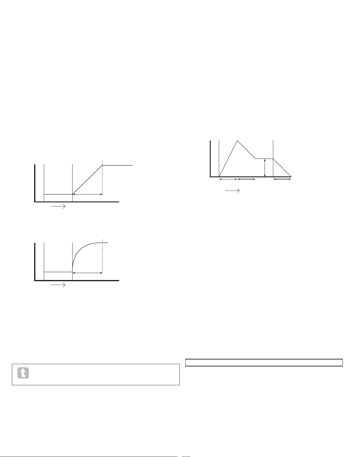
19
RE3 : Not used.
RE4 : Portamento Time
Displayed as: PortTime
Initial value: Off
Range of adjustment: Off, 1 to 127
With Portamento active, notes played sequentially glide from one to the next, rather than
immediately jumping to the desired note pitch. The synth remembers the last note played
and the glide will start from that note even after the key has been released. The Porta-
mento Time is the duration of the glide, and a value of 70 equates to approximately 1
second. Portamento is primarily intended for use in a mono Mode (see RE5 below), where
it is par ticularly effective. It can also be used in a Poly mode, but its operation can be unpredictable, particularly when chords are played. Note that Pre-Glide must be set to zero
in order for Portamento to be operative.
RE5: Portamento Mode
Displayed as: Port Mode
Initial value: Expo
Range of adjustment: Expo or Linear
This sets the ‘shape’ of the Portamento and Pre- Glide (see RE6 below) transitions from
one note to the next. In Linear mode, the glide alters the pitch evenly between the previous
note and that being played. In Expo mode, the pitch changes more rapidly at first, and then
approaches the ‘target’ note more slowly, i.e., exponentially.
RE6 : Pre- Glide
Displayed as: PreGlide
Initial value: 0
Range of adjustment: 0, -12 to +12
Pre-Glide takes priority over Portamento, though it does use the Portamento Time
parameter to set its duration. Pre-Glide is calibrated in semitones, and each note played
will actually begin a on a chromatically-related note up to an octave above (value = +12)
or below (value = -12) the note corresponding to the key pressed, and glide towards the
‘target’ note. This differs from Portamento in that, e.g., two notes played in sequence will
each have their own Pre-Glide, related to the notes played, and there will be no glide
‘between’ the notes.
Although the use of Portamento is not recommended in Poly modes when playing
more than one note at a time, this restriction does not apply to Pre-Glide, which
can be very effective with full chords.
RE7: Polyphony Mode
Displayed as: PolyMode
Initial value: Poly1
Range of adjustment: Mono, MonoAG, Poly1, Poly2, Mono2
As the names imply, three of the possible modes are mono and two are polyphonic.
Mono – this is standard monophonic mode; only one note sounds at a time, and the “last
played” rule applies.
MonoAG – AG stands for Auto-Glide. This is an alternative mono mode, which differs
from Mono in the way Portamento and Pre-Glide work. In Mono mode, Por tamento and
Pre-Glide apply both if notes are played separately, or in a legato style (when one note is
played when another is already held down). In MonoAG mode, Por tamento and Pre-Glide
only work if the keys are played in a legato style; playing notes separately produces no
glide effect.
Poly1 – in this polyphonic mode successively playing the same note(s) uses separate
voices and the notes are therefore ‘stacked’, so the sound gets louder as more notes are
played. The effect will only be evident on patches with a long amplitude release time.
Poly2 – in this alternative mode, successively playing the same note(s) uses the original
voices, so the volume increase inherent in Poly1 mode is avoided.
Mono 2 – this differs from Mono in the way the Attack phases of the Envelopes are triggered. In Mono mode, when playing Legato style, the envelopes are only triggered once, by
the initial key press. In Mono 2 mode, every key press will re-trigger all the Envelopes.
RE8: Not used
envelopeS
The UltraNova provides a great deal of flexibility in the use of envelopes in sound creation,
based on the familiar ADSR concept.
The ADSR envelope can be most easily visualised by considering the amplitude (volume)
of a note over time. The envelope describing the “lifetime” of a note can be split into four
distinct phases, and adjustments are provided for each of these:
Attack – the time it takes for the note to increase from zero (e.g. when the key is pressed)
to its maximum level. A long attack time produces a “fade-in” effect.
Decay – the time it takes for the note to drop in level from the maximum value reached at
the end of the attack phase to a new level, defined by the Sustain parameter.
Sustain – this is an amplitude value, and represents the volume of the note after the initial
attack and decay phases – i.e., while holding the key down. Setting a low value of Sustain
can give a very short, percussive ef fect (providing the attack and decay times are short).
Release – This is the time it takes for the note’s volume to drop back to zero after the key is
released. A high value of Release will cause the sound to remain audible (though diminishing in volume) after the key is released.
Although the above discusses ADSR in terms of volume, note that the UltraNova is
equipped with six separate Envelope generators, allowing control of other synth blocks as
well as amplitude – e.g., filters, oscillators, etc.
Pressing the E NVELOPE button [15] opens the Envelope Menu, which has two pages for
each envelope. One of the SELECT buttons and one of the PAGE buttons will be illuminated, indicating that more than one envelope is available to be controlled and that further
menu pages are available. A total of 16 parameters per envelope is displayed for adjustment, eight per Page. Note that the last parameter on Page 2 is common to all envelopes,
and this appears on Page 2 for all envelopes.
Envelope 1 (Amplitude) parameters (Page 1)
Envelope generator 1 controls the ADSR parameters of the notes’ amplitudes.
RE1: Amplitude Attack Time
Displayed as: AmpA tt
Initial value: 2
Range of adjustment: 0 to 127
This parameter sets the note’s attack time. With a value of 0 the note is at its maximum
level immediately the key is pressed; with a value of 127, the note takes over 20 seconds
to reach its maximum level. At the mid-setting ( 64), the time is approx. 220 ms (provided
Amplitude Attack Slope (Page 2, RE1) has a value of zero).
TIME
KEY "ON" KEY "ON"
PITCH
Portamento Time
TIME
KEY "ON" KEY "ON"
PITCH
Portamento Time
ATTACK DECAY RELEAS E
SUSTAIN
TIME
KEY "ON" KEY "OFF"
VOLUME
O1Semi O1Cents O1VSync O1Wave O1PW/Idx O1Hard O1Dense O1DnsDtn
0 0 0 Sawtooth 0 127 0 0
O1PtchWh O1WTInt FixNote ModVib MVibRate OscDrift OscPhase NoiseTyp
+12 127 Off 0 65 0 0deg White
O2Semi O2Cents O2VSync O2Wave O2PW/Idx O2Hard O2Dense O2DnsDtn
0 0 0 Sawtooth 0 127 0 0
O2PtchWh O2WTInt FixNote ModVib MVibRate OscDrift OscPhase NoiseTyp
+12 127 Off 0 65 0 0deg White
O3Semi O3Cents O3VSync O3Wave O3PW/Idx O3Hard O3Dense O3DnsDtn
0 0 0 Sawtooth 0 127 0 0
O3PtchWh O3WTInt FixNote ModVib MVibRate OscDrift OscPhase NoiseTyp
+12 127 Off 0 65 0 0deg White
127 0
FBalance FRouting
-64 Parallel Off Off
127 0
FBalance FRouting
-64 Parallel Off Off
AmpAtt AmpDec AmpSus AmpRel AmpVeloc AmpRept AmpTTrig AmpMTrig
2 90 127 40 0 0 OFF Re-Trig
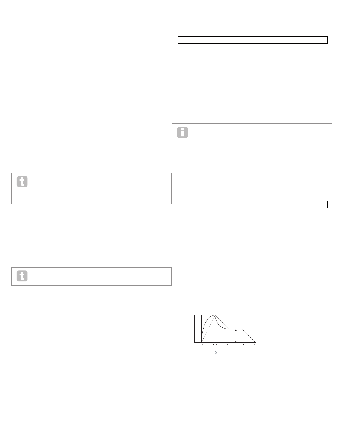
20
RE2 : Amplitude Decay Time
Displayed as: AmpD ec
Initial value: 90
Range of adjustment: 0 to 127
This parameter sets the notes’ decay time. Decay time only has meaning if the Sustain
parameter value is set to less than 127, as the Decay phase will be inaudible if the sustain
level is the same as the level reached during the attack phase. At the mid-setting (64), the
time is approx. 150 ms (provided Amplitude Decay Slope (Page 2, RE2) has a value of
127).
RE3 : Amplitude Sustain Level
Displayed as: AmpS us
Initial value: 127
Range of adjustment: 0 to 127
The value of the Sustain parameter sets the volume of the note after the completion of the
decay phase. Setting a low value will obviously have the ef fect of emphasising the start of
the note; setting it to zero will render the note silent after the decay phase has elapsed.
RE4 : Amplitude Release Time
Displayed as: AmpR el
Initial value: 40
Range of adjustment: 0 to 127
Many sounds acquire some of their character from the notes remaining audible after the key
is released; this “hanging” or “fade-out” effect, with the note gently dying away naturally (as
with many real instruments) can be very effective. A setting of 64 gives a Release Time of
approx. 300 ms. The UltraNova has a maximum release time of approx. 30 seconds (with
Release set to 127), but shorter times will probably be more useful! The relationship
between the parameter value and the Release Time is not linear – see the graph below.
Note that when playing polyphonically with sounds having long release times, it is
possible for ‘Voice Stealing’ to occur. This means that some notes still sounding
(in their Release phase) might suddenly cut off when other notes are played. This
is more likely to happen when multiple Voices are in use. See page 18 for more
information on this topic.
RE5: Amplitude Velocity
Displayed as: AmpV eloc
Initial value: 0
Range of adjustment: -64 to +63
Amplitude Velocity does not modify the shape of the ADSR amplitude envelope in any
way, but adds touch sensitivity to overall volume, so that with positive parameter values,
the harder you play the keys, the louder will be the sound. With Amplitude Velocity set
to zero, the volume is the same regardless of how the keys are played. The relationship
between the velocity at which a note is played and volume is determined by the value. Note
that negative values have the inverse effect.
For the most “natural” playing style, try setting Amplitude Velocity to about +40.
RE6 : Amplitude Envelope Repeat
Displayed as: AmpR ept
Initial value: 0
Range of adjustment: 0 to 126, KeyOff
By using Amplitude Repeat, it is possible to repeat the Attack and Decay phases of the
envelope before the Sustain phase is initiated. This can produce an interesting “stuttering”
effect at the start of the note if the Attack and Decay times are set appropriately. The value
of the Repeat parameter (from 0 to 126) is the actual number of repeats, so that if you set it
to, e.g. 3, you will hear a total of four attack /decay phases of the envelope – the initial one,
plus three repeats. The maximum setting of KeyOff generates an infinite number of repeats.
RE7: Amplitude Touch Trigger
Displayed as: AmpTTrig
Initial value: Off
Range of adjustment: Off, T1ReTrig to T8ReTrig
You will have noticed that the UltraNova’s rotar y encoders are touch-sensitive – the associated LED illuminates as soon as the knob is touched. This touch sensitivity can be utilised
in real time to provide creative control over the sound, which is especially useful when
playing live.
Amplitude Touch Trigger assigns any one of the encoder knobs to act as a re-trigger button – as soon as the knob is touched, the amplitude envelope is re-triggered. After making
the assignment, in order to use the feature it is necessary to open the Animate Touch mode
by pressing the TOUCH button [22] (select Page 1 if it is not already visible); you will see
that an ‘R’ appears under RE1, below the selected encoder to confirm the assignment of
Envelope1 to that encoder. The touch-sensitive knob is now active.
RE8: Amplitude Multi-trigger
Displayed as: AmpM Trig
Initial value: Re-Trig
Range of adjustment: Legato or Re-Trig
When this parameter is set to Re-Trig, each note played will trigger its full ADSR amplitude
envelope, even if other keys are held down. In Legato mode, only the first key to be pressed
will produce a note with the full envelope, all subsequent notes will omit the attack and
decay phases, and sound only from the start of the Sustain phase. “Legato” literally means
“smoothly”, and this mode aids this style of playing.
It is important to appreciate that for the Legato mode to be operative, mono voicing must
be selected – it will not work with polyphonic voicing. See page 19
What is Legato?
As stated above, the musical term Legato means “smoothly”. A Legato keyboard
style is one where at least two notes overlap. This means that as you play the
melody, you keep the previous (or an earlier) note sounding as you play another
note. Once that note is sounding, you then release the earlier note.
Legato style playing is relevant to some of the UltraNova’s sonic possibilities. In the case
of Amplitude Multi-Trigger, for example, it is impor tant to appreciate that the envelope will
re-trigger if any ‘gap’ is left between notes.
Envelope 1 (Amplitude) parameters (Page 2)
RE1: Amplitude Attack Slope
Displayed as: AmpA tSlp
Initial value: 0
Range of adjustment: 0 to 127
This parameter controls the “shape” of the attack characteristic. With a value of 0, the
volume increases linearly during the attack phase – that is to say, increases by equal
amounts in equal time intervals. A non-linear attack characteristic may be selected as an
alternative, where the volume increases more rapidly at first. The diagram below illustrates this:
RE2 : Amplitude Decay Slope
Displayed as: AmpD cSlp
Initial value: 127
Range of adjustment: 0 to 127
This parameter applies the same function as Amplitude Attack Slope to the Decay phase
of the envelope. With a value of 0, the volume drops linearly from the maximum value to that
defined by the Sustain parameter, but setting Decay Slope to a higher value will cause the
volume to reduce more rapidly initially. The diagram below illustrates this:
RE3 : Amplitude Attack Track
Displayed as: AmpA ttTk
Initial value: 0
Range of adjustment: -64 to +63
This parameter relates a note’s attack time to its position on the keyboard. When
Amplitude Attack Track has a positive value, the attack time of a note decreases the
higher up the keyboard it is played. Conversely, lower notes have a longer attack time. This
aids in simulating the effect of a real stringed instrument (such as a grand piano), where
the mass of the strings on the lower notes have a slower response time when struck. When
a negative value is applied, the relationships are reversed.
0 0 0 64 64 64
DELAY1 Dly1Time Dly1Sync Dly1Fbck Dly1L/R Dly1Wdth DLy1Slew
64 Off 64 1/1 127 127
CHORUS1 Ch1Type Ch1Rate Ch1Sync Ch1Fbck Ch1Depth Ch1Delay
Chorus 20 Off +10 64 64
GATOR GtOn/Off GtLatch GtRSync GtKSync GtSlew GtDecay GtL/Rdel
On Off 16th On 16 64 0
GATOR GtMode EditGroup EEEE---- --------
Mono16 1 -------- --------
A000 Init Program
Patch Name Find By Category Genre
A000 Init Program A000-D127 All All
PATCHSAVE Posng *------- -------- Upper Lower Number Punctuate
A o Init Program A a 0 space
PATCHSAVE Bank Patch Destination SaveCatg SaveGenre
Dest+C&G A 0 Init Program None None
---- ---- ---- ---- ---- ---- ---- ----
---- ---- ---- ---- ---- ---- ---- ----
0 ------ 0 ------ 0 ------ 0 ------ 0 ------ 0 ------ 0 ------ 0 ------
NmbrMods NmbrMods NmbrMods NmbrMods NmbrMods NmbrMods NmbrMods NmbrMods
0 0 0 0 0 0 0 0
E123456 E123456 E123456 E123456 E123456 E123456 E123456 E123456
----- ----- ----- ----- ----- ----- ----- -----
M 123456 M 123456 M 123456 M 123456 M 123456 M 123456 M 123456 M 123456
0 R----- 0 ------ 0 ------ 0 ------ 0 ------ 0 ------ 0 ------ 0 ------
O1Semi O1Cents O1VSync O1Wave O1PW/Idx O1Hard O1Dense O1DnsDtn
0 0 0 Sawtooth 0 127 0 0
O1PtchWh O1WTInt FixNote ModVib MVibRate OscDrift OscPhase NoiseTyp
+12 127 Off 0 65 0 0deg White
O2Semi O2Cents O2VSync O2Wave O2PW/Idx O2Hard O2Dense O2DnsDtn
0 0 0 Sawtooth 0 127 0 0
O2PtchWh O2WTInt FixNote ModVib MVibRate OscDrift OscPhase NoiseTyp
+12 127 Off 0 65 0 0deg White
O3Semi O3Cents O3VSync O3Wave O3PW/Idx O3Hard O3Dense O3DnsDtn
0 0 0 Sawtooth 0 127 0 0
O3PtchWh O3WTInt FixNote ModVib MVibRate OscDrift OscPhase NoiseTyp
+12 127 Off 0 65 0 0deg White
127 0
FBalance FRouting
-64 Parallel Off Off
127 0
FBalance FRouting
-64 Parallel Off Off
AmpAtt AmpDec AmpSus AmpRel AmpVeloc AmpRept AmpTTrig AmpMTrig
2 90 127 40 0 0 OFF Re-Trig
AmpAtSlp AmpDcSlp AmpAttTk AmpDecTk AmpSusRt AmpSusTm AmpLvlTk LvlTkNte
0 127 0 0 0 127 0 C 3
ATTACK DECAY RE LEASE
SUSTAIN
TIME
KEY "ON" KEY "OFF"
VOLUME
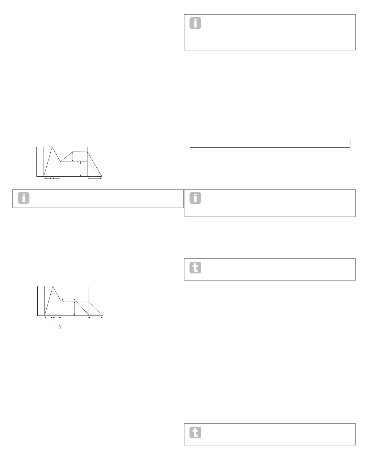
21
RE4 : Amplitude Decay Track
Displayed as: AmpD ecTk
Initial value: 0
Range of adjustment: -64 to +63
This parameter works in exactly the same way as Attack Track, except that it is the Decay
time of a note that becomes dependent on its position on the keyboard.
RE5: Amplitude Sustain Rate
Displayed as: AmpS usRt
Initial value: Flat
Range of adjustment: -64 to Flat to + 63
With this parameter set to Flat, the volume during the Sustain phase of the envelope remains constant. Additional variations to a note’s character can be obtained by causing the
note to become louder or quieter while the key is held. A positive value of Sustain Rate
will cause the volume to increase during the Sustain phase, and it will continue to do so
until maximum level is reached. The parameter controls the rate at which the note increases
volume, and the higher the value, the faster the rate of increase. Any Release time set will
act as normal when the key is released, whether or not the maximum volume has been
reached. If a negative value is set, the volume during the Sustain phase drops, and if the
key is not released, the note will eventually become inaudible.
Lower values (positive or negative) of Amplitude Sustain Rate are generally
more useful.
RE6 : Amplitude Sustain Time
Displayed as: AmpS usTm
Initial value: 127
Range of adjustment: 0 to 126, KeyOff
This parameter sets the duration of the Sustain phase. With a value of KeyOff, the note will
remain audible continuously until the key is released (unless a negative value of Sustain
Rate has been applied to reduce its volume). Any other value of Sustain Time will cut
the note off automatically after a pre-determined time if the key is still held down. Release
Time still applies if the key is released sooner. A value of 126 sets the Sustain time to approx. 10 seconds, while values around 60 set it to about 1 second.
RE7: Amplitude Level Track
Displayed as: AmpLvlTk
Initial value: 0
Range of adjustment: -64 to +63
This parameter works in a similar way to the other “tracking” parameters Attack Track and
Decay Track (RE3 & RE4), but it is the volume of the note which is changed, according to
the interval between it and the Track Note set by RE8. With a positive value, notes higher
than the Track Note get progressively louder the further from the Track Note they are, and
vice-versa . With a negative value, notes higher than the Track Note get progressively quieter the further from the Track Note they are, and again, vice-versa. Note that this volume
modification is applied to all phases of the amplitude envelope equally; it is the overall
volume of the note which changes with Level Track. The effect should be used sparingly;
low values have a better effect.
Note that although Amplitude Level Track appears to operate in a very similar
manner to Amplitude Attack Track and Amplitude Decay Track, only Level Track
uses a user-definable note as the reference (set by RE8 ), above which notes
get louder and below which get softer. The Attack and Decay Track parameters (RE3 and
RE4 ) have a fixed reference note at C 3.
Common Envelope Parameter
This parameter is available on Page 2 of the menu for every Envelope.
RE8: Level Track Reference Note
Displayed as: LvlTkNte
Initial value: C 3
Range of adjustment: C -2 to G 8
This sets the reference note used for Amplitude Level Track. When active, this parameter
increases the volume for notes above the chosen Track Note, and reduces it for notes
below it. C 3, the default value, is Middle C on the keyboard; this is the C one octave above
the lowest note on the keyboard (also C), providing no OC TAVE buttons [32] are selected.
Envelope 2 (Filter) parameters (Page 1)
The parameters available for adjustment with Envelope generator 2 closely match those for
Envelope generator 1. Whereas Envelope 1 is concerned with modifications to the sound’s
amplitude envelope, Envelope 2 gives you “dynamic” filtering, by establishing a relationship
between the filter section and ADSR Filter Envelope 2, resulting in the filter frequency being varied by the shape of the envelope.
In order to hear the effect of any of the Filter Envelope parameters, you will first
need to go to the Filter Menus and set up some filtering. Then set RE5 on Filter
Menu Page 1 (F1Env2 or F2Env2 ) to an initial value of approx. +30 and ensure
that the filter is not fully open – i.e., set F1Freq to mid-range.
RE1: Filter Attack Time
Displayed as: FltAtt
Initial value: 2
Range of adjustment: 0 to 127
This parameter sets how the filter section acts during the note’s Attack phase. The higher
the value, the longer it takes for the filter to react during this phase.
To evaluate the action of the Filter Envelope parameters for each of the ADSR
phases (RE1 to RE4), it may be helpful not to set all three to zero.
RE2 : Filter Decay Time
Displayed as: FltDec
Initial value: 75
Range of adjustment: 0 to 127
This parameter sets how the filter section acts during the note’s Decay phase. Again, the
higher the parameter value, the longer the period for which filtering is applied .
RE3 : Filter Sustain Level
Displayed as: FltSus
Initial value: 35
Range of adjustment: 0 to 127
The frequency of the filter (cut-off or centre, depending on filter type) “settles” at a value
set by the Filter Sustain Level. Thus, once the Attack and Decay stages of the envelope
are completed, the harmonic content that will be most evident in the sound will be determined by this parameter. Remember that if the filter frequency parameter (as set in the Filter
Menu) is set at a too low or too high a value, the envelope’s ef fect will be limited.
RE4 : Filter Release Time
Displayed as: FltRel
Initial value: 45
Range of adjustment: 0 to 127
As Filter Release is increased in value, the note undergoes increasingly more filter action
once the key is released.
Note that the Amplitude Release time (in Envelope 1’s parameters) must be set
sufficiently high to produce an audible “fade-out” before the ef fect of filtering on
the “tail” of the note is evident.
ATTACK DECAY
RELEASE
SUSTAIN
SUSTAIN
RATE
KEY "ON" KEY "OFF"
VOLUME
ATTACK DECAY
RELEASE
SUSTAIN
SUSTAIN TIME
TIME
KEY "ON" KEY "OFF"
VOLUME
O1Semi O1Cents O1VSync O1Wave O1PW/Idx O1Hard O1Dense O1DnsDtn
0 0 0 Sawtooth 0 127 0 0
O1PtchWh O1WTInt FixNote ModVib MVibRate OscDrift OscPhase NoiseTyp
+12 127 Off 0 65 0 0deg White
O2Semi O2Cents O2VSync O2Wave O2PW/Idx O2Hard O2Dense O2DnsDtn
0 0 0 Sawtooth 0 127 0 0
O2PtchWh O2WTInt FixNote ModVib MVibRate OscDrift OscPhase NoiseTyp
+12 127 Off 0 65 0 0deg White
O3Semi O3Cents O3VSync O3Wave O3PW/Idx O3Hard O3Dense O3DnsDtn
0 0 0 Sawtooth 0 127 0 0
O3PtchWh O3WTInt FixNote ModVib MVibRate OscDrift OscPhase NoiseTyp
+12 127 Off 0 65 0 0deg White
127 0
FBalance FRouting
-64 Parallel Off Off
127 0
FBalance FRouting
-64 Parallel Off Off
AmpAtt AmpDec AmpSus AmpRel AmpVeloc AmpRept AmpTTrig AmpMTrig
2 90 127 40 0 0 OFF Re-Trig
AmpAtSlp AmpDcSlp AmpAttTk AmpDecTk AmpSusRt AmpSusTm AmpLvlTk LvlTkNte
0 127 0 0 0 127 0 C 3
FltAtt FltDec FltSus FltRel FltVeloc FltRept FltTTrig FltMTrig
2 75 35 45 0 0 OFF Re-Trig

22
RE5: Filter Velocity
Displayed as: FltVeloc
Initial value: 0
Range of adjustment: -64 to +63
As Amplitude Velocity adds touch sensitivity to volume, so Filter Velocity can be set to
make filter action touch sensitive. With positive parameter values, the harder you play the
keys, the greater will be the effect of the filter. With Filter Velocity set to zero, the sound’s
characteristics are the same regardless of how the keys are played. Note that negative
values have the inverse ef fect.
RE6 : Filter Repeat
Displayed as: FltRept
Initial value: 0
Range of adjustment: 0 to 126, Infinity
When Filter Repeat is set to a value other than zero, the Attack and Decay phases of the
envelope are repeated before the Sustain phase is initiated. This has a similar effect to
Amplitude Repeat and use of either both repeat parameters can create some be quite
striking sounds.
RE7: Filter Touch Trigger
Displayed as: FltTTrig
Initial value: Off
Range of adjustment: Off, T1ReTrig to T8ReTrig, T1Trig to T8Trig, T1Enable to T8Enable
Unlike Amplitude Touch Trigger, Filter Touch Trigger has three options per touchsensitive control: Trigger, Re-trigger and Enable. However, as with Amplitude Touch
Trigger, it is necessary to enable the Animate Touch mode by pressing the TOUCH
button [22] in order to use the function.
Re-Trigger – acts in a similar way to Amplitude Re-Trigger, except that it is the filter action which is re-triggered by touching the selected encoder knob. The note plays as normal
when the key is pressed, touching the knob re-triggers the entire envelope. Re-Trigger
mode is confirmed on Page 1 of the Animate Touch menu by the letter ‘R’ in the appropriate
position.
Trigger - in this mode, the envelope-triggered filter action is not initiated by pressing a
key, and the note will initially sound with no envelope acting on the filter. Touching the knob
(while the key is pressed) will trigger the filter envelope. Trigger mode is confirmed on
Page 1 of the Animate Touch menu by the letter ‘T’ in the appropriate position.
Enable – in this mode, the envelope-triggered filter action is initiated by the keyboard, but
only while the knob is being touched. Thus you can very easily flip between the sound with
and without the action of the envelope on the filter. Enable mode is confirmed on Page 1 of
the Animate Touch menu by the letter ‘E’ in the appropriate position.
RE8: Filter Multi-trigger
Displayed as: FltMTrig
Initial value: Re-Trig
Range of adjustment: Legato or Re-Trig
This operates in a very similar way to Amplitude Multi-trigger. When set to Re-Trig,
each note played will trigger its full ADSR envelope, even if other keys are held down.
With the envelope applied to the filter section, this means that the effect of any envelopetriggered filtering will be heard on every note. When set to Legato, only the first key to be
pressed will produce a note with the full envelope and thus produce any filtering effect. All
subsequent notes will lack any dynamic filtering. Remember that for the Legato mode to be
operative, mono voicing must be selected – it will not work with polyphonic voicing. See page 18.
See page 20for more details about Legato style.
Envelope 2 (Filter) parameters (Page 2)
RE1: Filter Attack Slope
Displayed as: FltAtSlp
Initial value: 0
Range of adjustment: 0 to 127
This parameter controls the “shape” of the attack characteristic as applied to the filters.
With a value of 0, any filtering effect applied to the Attack phase increases linearly – that is
to say, increases by equal amounts in equal time intervals. A non-linear attack characteristic
may be selected as an alternative, where the filter effect increases more rapidly at first.
RE2 : Filter Decay Slope
Displayed as: FltDcSlp
Initial value: 127
Range of adjustment: 0 to 127
This corresponds to Filter Attack Slope in the same manner that Amplitude Decay
Slope corresponds to Amplitude Attack Slope. Thus the linearity of the reaction of the
filter section during the Decay phase of the envelope can be varied, from linear to a more
exponential slope, where any filter effect is more pronounced during the first part of the Decay
phase.
RE3 : Filter Attack Track
Displayed as: FltAttTk
Initial value: 0
Range of adjustment: -64 to +63
Like Amplitude Attack Track, this parameter relates a note’s attack time to its position on
the keyboard. When Filter Attack Track has a positive value, the filtering effect during the
Attack phase of a note is shortened as you go up the keyboard. Conversely, lower notes
have their attack time increased. When a negative value is applied, the relationships are
reversed.
RE4 : Filter Decay Track
Displayed as: FltDecTk
Initial value: 0
Range of adjustment: -64 to +63
This parameter works in exactly the same way as Attack Track, except that it is the filter
effect during the Decay phase of a note that becomes dependent on its keyboard position.
RE5: Filter Sustain Rate
Displayed as: FltSusRt
Initial value: Flat
Range of adjustment: -64 to Flat to + 63
With a value of Flat, filter frequency remains constant during the Sustain phase of the note.
If Filter Sustain Rate is given a positive value, the filter frequency continues to increase
during the Sustain phase, thus the character of the note continues altering audibly for
longer. With low values of Filter Sustain Rate, the change is slow, and increases in rapidity as the value is increased. With negative values, the filter frequency decreases during the
Sustain phase. See page 21 for an illustration.
RE6 : Filter Sustain Time
Displayed as: FltSusTm
Initial value: 127
Range of adjustment: 0 to 126, Keyoff
This parameter also applies to the Sustain phase, and sets how long any envelope-triggered filtering remains active. When set to Keyoff, the filtering remains applied continuously until the key is released. Any lower value of Sustain Time will cause the filtering
effect to suddenly stop before the note ends, and you will be left with release phase of the
envelope. This does, of course, only occur if the Amplitude Sustain Time is longer than
the Filter Sustain Time, otherwise the note will stop sounding altogether before the filter
has cut off.
RE7: Filter Level Track
Displayed as: FltLvlTk
Initial value: 0
Range of adjustment: -64 to +63
This parameter works in a similar way to the other “tracking” parameters, but it is the depth
with which the envelope is applied to the filter which alters, in relation to the interval between the note played and the Track Note set by RE8. With a positive value, the envelopetriggered filtering effect becomes progressively more pronounced for notes higher than
the Track Note the further from the Track Note they are, and vice-versa. With a negative
value, notes higher than the Track Note undergo progressively less filtering the further
from the Track Note they are, and again, vice-versa.
Common Envelope Parameter
See page 21. The Track Reference Note parameter is available at RE8 on Page 2 of the
menu for every Envelope.
Envelopes 3 to 6 parameters (Page 1)
In addition to dedicated Amplitude and Filter envelopes, the UltraNova is equipped with
four fur ther assignable envelopes, Envelopes 3 to 6. Control of these can be selected with
the SELECT button [10]. These envelopes have virtually the same set of parameters as the
O1Semi O1Cents O1VSync O1Wave O1PW/Idx O1Hard O1Dense O1DnsDtn
0 0 0 Sawtooth 0 127 0 0
O1PtchWh O1WTInt FixNote ModVib MVibRate OscDrift OscPhase NoiseTyp
+12 127 Off 0 65 0 0deg White
O2Semi O2Cents O2VSync O2Wave O2PW/Idx O2Hard O2Dense O2DnsDtn
0 0 0 Sawtooth 0 127 0 0
O2PtchWh O2WTInt FixNote ModVib MVibRate OscDrift OscPhase NoiseTyp
+12 127 Off 0 65 0 0deg White
O3Semi O3Cents O3VSync O3Wave O3PW/Idx O3Hard O3Dense O3DnsDtn
0 0 0 Sawtooth 0 127 0 0
O3PtchWh O3WTInt FixNote ModVib MVibRate OscDrift OscPhase NoiseTyp
+12 127 Off 0 65 0 0deg White
127 0
FBalance FRouting
-64 Parallel Off Off
127 0
FBalance FRouting
-64 Parallel Off Off
AmpAtt AmpDec AmpSus AmpRel AmpVeloc AmpRept AmpTTrig AmpMTrig
2 90 127 40 0 0 OFF Re-Trig
AmpAtSlp AmpDcSlp AmpAttTk AmpDecTk AmpSusRt AmpSusTm AmpLvlTk LvlTkNte
0 127 0 0 0 127 0 C 3
FltAtt FltDec FltSus FltRel FltVeloc FltRept FltTTrig FltMTrig
2 75 35 45 0 0 OFF Re-Trig
FltAtSlp FltDcSlp FltAttTk FltDecTk FltSusRt FltSusTm FltLvlTk LvlTkNte
0 127 0 0 0 127 0 C 3
10 70 64 40 0 0 OFF Re-Trig

23
Amplitude and Filter envelopes, but they can be assigned at will to control many other synth
functions, including most oscillator parameters, filters, EQ and panning among others.
The assignment of Envelopes 3 to 6 to other synth parameters is performed in the Modulation Menu (see page 25 for full details). In order to audition their effects, you must first
open the Modulation Menu and set Modulation Patch 1’s Source to Env3 and the
Destination to a parameter of your choice ( e.g. Global Oscillator Pitch – 0123Ptch).
The arrangement of parameters for Envelopes 3 to 6 is identical, and the arrangement
closely follows that of Envelopes 1 and 2 (Amplitude and Filters). Although denoted as
Envelope 3, the parameter summaries below apply equally to Envelopes 3, 4, 5 & 6, so are
not repeated.
The actual function of Envelopes 3 to 6 will obviously depend on what they are routed
to control in the Modulation Menu. However, the derivation of the envelope parameters
themselves follow those already described for the Amplitude and Filter envelopes, with the
exception of the Delay parameter (Page 1, RE5), whose function is described below.
RE1: Envelope 3 Attack Time
Displayed as: E3Att
Initial value: 10
Range of adjustment: 0 to 127
RE2 : Envelope 3 Decay Time
Displayed as: E3De c
Initial value: 70
Range of adjustment: 0 to 127
RE3 : Envelope 3 Sustain Level
Displayed as: E3Su s
Initial value: 64
Range of adjustment: 0 to 127
RE4 : Envelope 3 Release Time
Displayed as: E3Rel
Initial value: 40
Range of adjustment: 0 to 127
RE5: Envelope 3 Delay
Displayed as: E3Delay
Initial value: 0
Range of adjustment: 0 to 127
This parameter delays the start of the entire envelope. When a key is pressed, its note
sounds normally, with Envelopes 1 and 2 acting as they are programmed. But any further
modulation ef fects triggered by Envelopes 3 to 6 will be delayed by a time set by the Delay
parameter. The maximum value of 127 represents a delay of 10 seconds, while a value of
about 60~70 represents a delay of approximately 1 second.
RE6 : Envelope 3 Repeat
Displayed as: E3Re peat
Initial value: 0
Range of adjustment: 0 to 127
RE7: Envelope 3 Touch Trigger
Displayed as: E3TTrig
Initial value: Off
Range of adjustment: Off, T1ReTrig to T8ReTrig, T1Trig to T8Trig, T1Enable to T8Enable
RE8: Envelope 3 Multi-trigger
Displayed as: E3MTrig
Initial value: Re-Trig
Range of adjustment: Legato or Re-Trig
Envelope 3 parameters (Page 2)
RE1: Envelope 3 Attack Slope
Displayed as: E3At Slp
Initial value: 0
Range of adjustment: 0 to 127
RE2 : Envelope 3 Decay Slope
Displayed as: E3Dc Slp
Initial value: 0
Range of adjustment: 0 to 127
RE3 : Envelope 3 Attack Track
Displayed as: E3AttTk
Initial value: 0
Range of adjustment: -64 to +63
RE4 : Envelope 3 Decay Track
Displayed as: E3De cTk
Initial value: 0
Range of adjustment: -64 to +63
RE5: Envelope 3 Sustain Rate
Displayed as: E3Su sRat
Initial value: 0
Range of adjustment: -64 to +63
RE6 : Envelope 3 Sustain Time
Displayed as: E3Su sTim
Initial value: 127
Range of adjustment: 0 to 127
RE7: Envelope 3 Level Track
Displayed as: E3LvlT k
Initial value: 0
Range of adjustment: -64 to +63
Common Envelope Parameter
See page 21. The Track Reference Note parameter is available at RE8 on Page 2 of the
menu for every Envelope.
lfoS
The UltraNova has three separate Low Frequency Oscillators (LFOs). These are designated LFO1, 2 and 3, are identical in terms of features, and can be used freely to modify
many other synth parameters, such as oscillator pitch or level, filters, panning, etc.
The assignment of LFOs 1 to 3 to other synth parameters is performed in the Modulation
Menu (see page 25 for full details). In order to audition their effects, you should first open
the Modulation Menu and set Modulation Patch 1’s Source to Lfo1+/- or Lfo1+
*
and the
Destination to a parameter of your choice. Note also that the Depth control on this menu
(RE6) determines the amount of LFO modulation applied to the Destination parameter,
and increasing this value will have a different effect depending on what the Destination parameter is, but can generally be taken to mean “more effect”. The interpretation of negative
values of Depth will also depend on the chosen Destination parameter.
The LFO section has its own set of three LEDs, one per LFO. These monitor the output of each
LFO to provide a convenient visual reference as to their frequency, waveform and phase.
Pressing the LFO button [16] opens the LFO Menu, which has two pages for each LFO.
One of the SELECT buttons and one of the PAGE buttons will be illuminated, indicating
that more than one LFO is available to be controlled and that further menu pages are available. A total of 12 parameters per LFO is displayed for adjustment, eight on Page 1 and
four on Page 2. Because the three LFOs’ parameters are identical, only the functions of
LFO1 are described.
*
Selecting Lfo1+ as the source makes the LFO vary the controlled parameter in a
positive sense (i.e. increasing ) only. Selecting it as Lfo1+/- varies it in both a positive and
a negative sense. These options, and others related to them, are discussed in greater detail
at page 25.
LFO 1 parameters (Page 1)
RE1: LFO 1 Rate
Displayed as: L1Rate
Initial value: 68
Range of adjustment: 0 to 127
Rate is the oscillator’s frequency. A value of 0 disables the LFO, and most musical effects
O1Semi O1Cents O1VSync O1Wave O1PW/Idx O1Hard O1Dense O1DnsDtn
0 0 0 Sawtooth 0 127 0 0
O1PtchWh O1WTInt FixNote ModVib MVibRate OscDrift OscPhase NoiseTyp
+12 127 Off 0 65 0 0deg White
O2Semi O2Cents O2VSync O2Wave O2PW/Idx O2Hard O2Dense O2DnsDtn
0 0 0 Sawtooth 0 127 0 0
O2PtchWh O2WTInt FixNote ModVib MVibRate OscDrift OscPhase NoiseTyp
+12 127 Off 0 65 0 0deg White
O3Semi O3Cents O3VSync O3Wave O3PW/Idx O3Hard O3Dense O3DnsDtn
0 0 0 Sawtooth 0 127 0 0
O3PtchWh O3WTInt FixNote ModVib MVibRate OscDrift OscPhase NoiseTyp
+12 127 Off 0 65 0 0deg White
127 0
FBalance FRouting
-64 Parallel Off Off
127 0
FBalance FRouting
-64 Parallel Off Off
AmpAtt AmpDec AmpSus AmpRel AmpVeloc AmpRept AmpTTrig AmpMTrig
2 90 127 40 0 0 OFF Re-Trig
AmpAtSlp AmpDcSlp AmpAttTk AmpDecTk AmpSusRt AmpSusTm AmpLvlTk LvlTkNte
0 127 0 0 0 127 0 C 3
FltAtt FltDec FltSus FltRel FltVeloc FltRept FltTTrig FltMTrig
2 75 35 45 0 0 OFF Re-Trig
FltAtSlp FltDcSlp FltAttTk FltDecTk FltSusRt FltSusTm FltLvlTk LvlTkNte
0 127 0 0 0 127 0 C 3
10 70 64 40 0 0 OFF Re-Trig
E3AtSlp E3DcSlp E3AttTk E3DecTk E3SusRat E3SusTim E3LvlTk LvlTkNte
0 127 0 0 0 127 0 C 3
127 0 0 0 0 0 0dB 0dB
Off Off Off Off Off Off
Off Expo 0 Poly1 Off 25
L1Rate L1RSync L1Wave L1Phase L1Slew L1KSync L1Comn L1OneSht
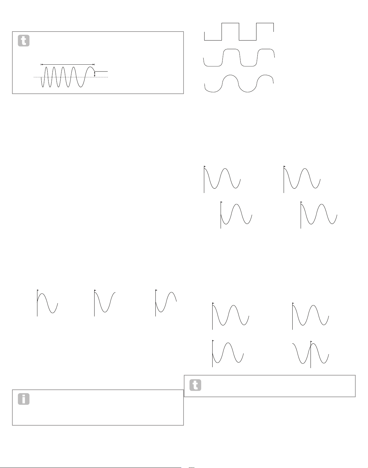
24
NOTE 1
KEY "ON"
NOTE 2
KEY "ON"
NOTE 1
KEY "ON"
NOTE 2
KEY "ON"
NOTE 1
NOTE 2
KEY "ON"
NOTE 1
NOTE 2
KEY "ON"
are likely to use values in the 40~70 range, though higher or lower values may be
appropriate for certain sound effects.
When the LFO Rate is set to zero, the LFO is “stopped”, but will still apply an
offset to the parameter it is modulating of a magnitude dependent on where it
stopped in its cycle.
RE2 : LFO 1 Rate Sync
Displayed as: L1RSync
Initial value: Off
Range of adjustment: See table at page 40.
This control allows the frequency of the LFO to be synchronised to an internal/external
MIDI clock. When set to Off, the LFOs run at a frequency set by the Rate parameter
(RE1). At all other settings RE1 becomes inoperative, and the LFO rate is determined by
Rate Sync , which in turn is derived from the MIDI clock. When using inernal MIDI clock,
the rate can be set in the Arp Edit Menu with RE8.
RE3 : LFO 1 Waveform
Displayed as: L1Wave
Initial value: Sine
Range of adjustment: see table at page 41.
The UltraNova’s LFOs are able to generate not only the familiar sine, sawtooth, triangle and
square waveforms for modulation purposes, but are also able to produce a wide range of
preset sequences of various lengths and random waveforms. A common use of an LFO is
to modulate the main oscillator(s), and with many of the sequenced waveforms, setting the
Depth parameter in the Modulation Menu to either 30 or 36 ( see table) will ensure that the
resulting oscillator pitches will be musically associated in some way.
RE4 : LFO 1 Phase
Displayed as: L1Phase
Initial value: 0
Range of adjustment: 0deg to 357deg
This control is only active if L1KSync ( RE6 ) is set On. It determines the start point of the
LFO waveform when the key is pressed. A complete waveform has 360º, and the control’s
increments are in 3º steps. Thus a half-way setting (180deg) will cause the modulating
waveform to start at half-way through its cycle.
RE5: LFO 1 Slew
Displayed as: L1Slew
Initial value: Off
Range of adjustment: Off, 1 to 127
Slew has the effect of modifying the shape of the LFO waveform. Sharp edges become
less sharp as Slew is increased. The effect of this can be easily observed by selecting
Square as the LFO waveform and setting the rate fairly low so that the output when a key
is pressed alternates between just two tones. Increasing the value of Slew will cause the
transition between the two tones to become a “glide” rather than a sharp change. This is
caused by the ver tical edges of the square LFO waveform being slewed.
Note that Slew has an effect on all LFO waveforms, including sine. The effect of
LFO Slew differs somewhat with different LFO waveforms. As Slew is increased,
the time taken to reach maximum amplitude is increased, and can ultimately result
in it never being achieved at all, though the setting at which this point is reached
will vary with waveform.
RE6 : LFO 1 Key Sync On/Off
Displayed as: L1KSync
Initial value: Off
Range of adjustment: On or Off
Each LFO is runs continuously, ‘in the background’. If the Key Sync setting is Off, there
is no way of predicting where the waveform will be when a key is pressed. Consecutive
presses of a key will inevitably produce varying results. Setting Key Sync to On re-starts
the LFO at the same point on the waveform every time a key is pressed. The actual point is
set by the Phase parameter (RE3).
RE7: LFO 1 Common Sync
Displayed as: L1Comn
Initial value: Off
Range of adjustment: On or Off
Common Sync is only applicable to polyphonic voices. It ensures that the phase of the
LFO waveform is synchronised for every note being played. When to set Off, there is no
such synchronisation, and playing a second note while one is already pressed will result in
an unsynchronised sound as the modulations will be out of time.
Common Sync OFF Common Sync OFF
Set LFO Common Sync to On for an emulation of early analogue polyphonic
synths.
RE8: LFO 1 One -Shot
Displayed as: L1OneSht
Initial value: Off
Range of adjustment: On or Off
As its name suggests, setting this parameter to On causes the LFO to generate just a
single cycle of its waveform. Note that a full waveform cycle is always generated regardless
of the setting of LFO Phase; if LFO Phase is set to 90, the one-shot waveform will star t at
the 90 point, execute a full cycle, and end at 90.
KEY "ON"
KEY "ON"
PHASE = 0
O
PHASE = 90
O
PHASE = 180
O
KEY "ON"
OFFSET
LFO RATE = X LFO RATE = 0
SQUARE WAVE
NO SLEW
SMALL SLEW VALUE
LARGE SLEW VALUE
Key Sync OFF Key Sync ON
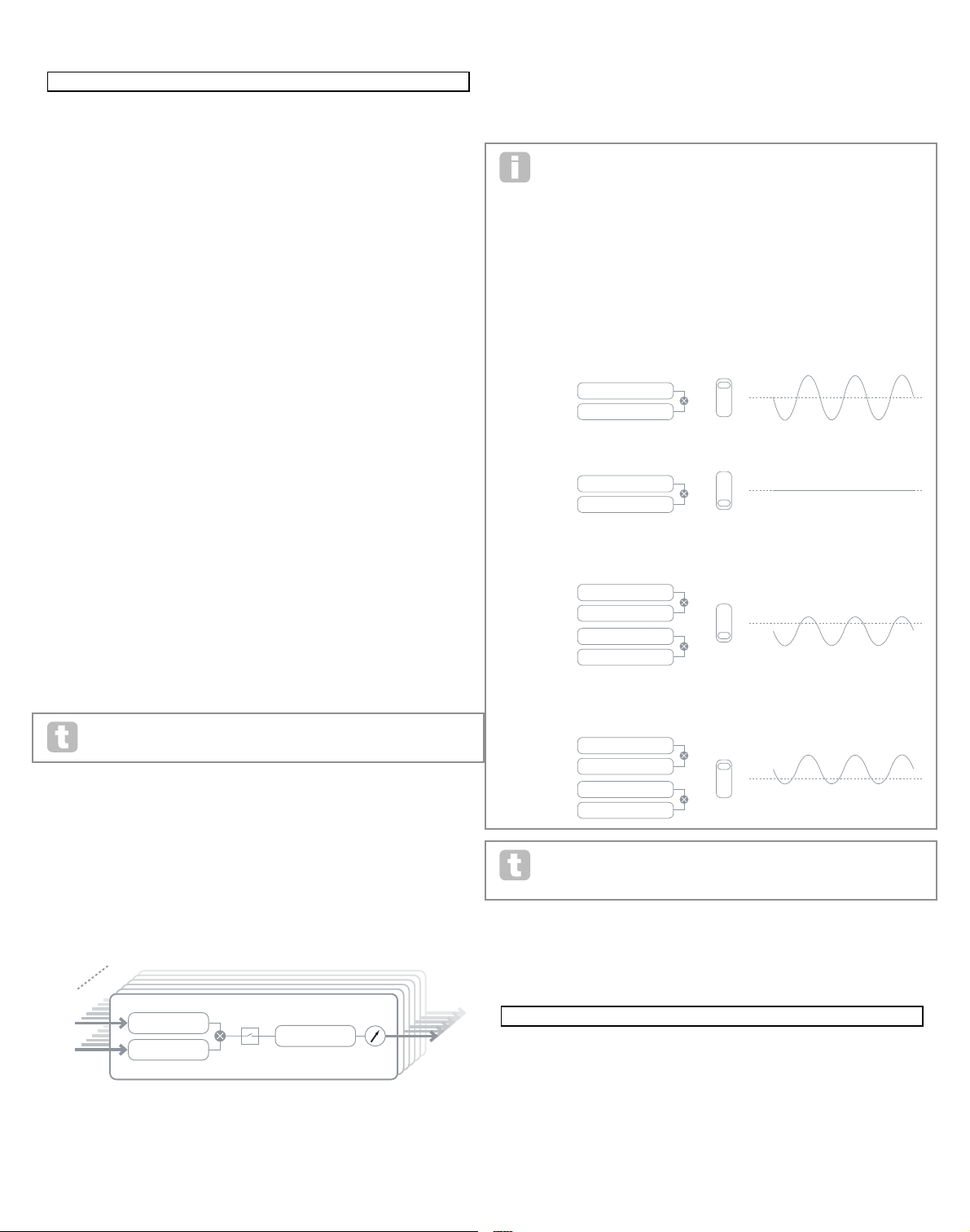
25
Pressing the MODULATION button [17] opens the Modulation Menu, which is a single
page. The menu may be visualised as a system for connecting controlling sources to a
specific area of the synth. Each such connection assignment is termed a ‘slot’, and there
are 20 such slots, accessed by RE1 (see below). Each slot defines how one or two control
sources are routed to a controlled parameter. The routing possibilities available in each of
the 20 slots are identical, and the control description below is applicable to all of them.
The Modulation Matrix is both variable and additive. What do we mean by a
‘variable’ and ‘additive’ matrix?
By ‘variable’, we mean that it is not just the routing of a controlling source to a controlled
parameter which is defined in each slot, but also the “magnitude” of the control. Thus the
‘amount’ of control – or control ‘range’ – used is up to you.
By ‘additive’ we mean that a parameter may be varied by more than one source, if wished.
Each slot allows for two sources to be routed to a parameter, and their effects are
multiplied together. This means that if either of them is at zero, there will be no modulation. However, there is no reason why you can’t have further slots routing these or other
sources to the same parameter. In this case, the control signals from different slots “add” to
produce the overall effect.
Mod Wheel Position
You need to be careful when setting up patches like this to ensure that the combined effect of all the controllers acting simultaneously still creates the sound
that you want.
In addition, the Modulation Menu lets you assign the touch-sensitive knobs on any of the
eight rotary encoders as additional controllers, so as long as the Animate Touch mode is
enabled (see page 26).
Modulation Matrix Menu
RE1: Patch number
Displayed as: Num ber
Initial value: 1
Range of adjustment: 1 to 20
The Modulation Matrix has 20 ‘slots’, each defining a routing assignment of one (or two)
sources to a destination. All the patches have the same selection of sources and destinations and any or all can be used. The same source can control multiple destinations, and
one destination can be controlled by multiple sources.
LFO 1 parameters (Page 2)
RE1: LFO 1 Delay
Displayed as: L1Dela y
Initial value: 0
Range of adjustment: 0 to 127
LFO Delay is a time parameter whose function is determined by L1InOut (RE3).
RE2 : LFO 1 Delay Sync
Displayed as: L1DSync
Initial value: Off
Range of adjustment: See table at page 40.
When this parameter is set to Off, the LFO delay is controlled by the Delay parameter
(RE1). At all other settings RE1 becomes inoperative, and the LFO delay is derived from
the internal/external MIDI clock.
RE3 : LFO 1 Fade In/Fade Out
Displayed as: L1In Out
Initial value: FadeIn
Range of adjustment: FadeIn, FadeOut, GateIn, GateOut
The function of the four possible settings of Intro are as follows:
FadeIn - the LFO’s modulation is gradually increased over the time period set by the Delay
parameter (RE1).
GateIn – the onset of the LFO’s modulation is delayed by the time period set by the LFO
Delay parameter, and then starts immediately at full level.
FadeOut – the LFO’s modulation is gradually decreased over the time period set by the
Delay parameter (RE1), leaving the note with no LFO modulation.
GateOut – the note is fully modulated by the LFO for the time period set by the Delay
parameter (RE1). At this time, the modulation stops abruptly.
RE4 : LFO1 Delay Trigger
Displayed as: L1DTrig
Initial value: Legato
Range of adjustment: Legato or Re-Trig
This parameter works in conjunction with the Fade In/ Fade Out function set by RE3. In
Re-Trig mode, every note played has its own delay time, as set by the Delay parameter ( or
MIDI clock if L1Dsync is active). In Legato mode, it is only the first note of a legato-style
passage which determines the Delay time – i.e. second and subsequent notes do not retrigger the Delay function. For the Legato setting of Delay Trigger to be operative, mono
voicing must be selected – it will not work with polyphonic voicing. See page 18.
See page 21 for more details about Legato style.
RE5-RE8: Not used
the moDulatIon matrIx
The heart of a versatile synthesizer lies in the ability to interconnect the various controllers,
sound generators and processing blocks such that one is controlling – or “modulating” another, in as many ways as possible. UltraNova provides tremendous flexibility of control
routing, and there is a dedicated menu for this, the Modulation Menu.
O1Semi O1Cents O1VSync O1Wave O1PW/Idx O1Hard O1Dense O1DnsDtn
0 0 0 Sawtooth 0 127 0 0
O1PtchWh O1WTInt FixNote ModVib MVibRate OscDrift OscPhase NoiseTyp
+12 127 Off 0 65 0 0deg White
O2Semi O2Cents O2VSync O2Wave O2PW/Idx O2Hard O2Dense O2DnsDtn
0 0 0 Sawtooth 0 127 0 0
O2PtchWh O2WTInt FixNote ModVib MVibRate OscDrift OscPhase NoiseTyp
+12 127 Off 0 65 0 0deg White
O3Semi O3Cents O3VSync O3Wave O3PW/Idx O3Hard O3Dense O3DnsDtn
0 0 0 Sawtooth 0 127 0 0
O3PtchWh O3WTInt FixNote ModVib MVibRate OscDrift OscPhase NoiseTyp
+12 127 Off 0 65 0 0deg White
127 0
FBalance FRouting
-64 Parallel Off Off
127 0
FBalance FRouting
-64 Parallel Off Off
AmpAtt AmpDec AmpSus AmpRel AmpVeloc AmpRept AmpTTrig AmpMTrig
2 90 127 40 0 0 OFF Re-Trig
AmpAtSlp AmpDcSlp AmpAttTk AmpDecTk AmpSusRt AmpSusTm AmpLvlTk LvlTkNte
0 127 0 0 0 127 0 C 3
FltAtt FltDec FltSus FltRel FltVeloc FltRept FltTTrig FltMTrig
2 75 35 45 0 0 OFF Re-Trig
FltAtSlp FltDcSlp FltAttTk FltDecTk FltSusRt FltSusTm FltLvlTk LvlTkNte
0 127 0 0 0 127 0 C 3
10 70 64 40 0 0 OFF Re-Trig
E3AtSlp E3DcSlp E3AttTk E3DecTk E3SusRat E3SusTim E3LvlTk LvlTkNte
0 127 0 0 0 127 0 C 3
127 0 0 0 0 0 0dB 0dB
Off Off Off Off Off Off
Off Expo 0 Poly1 Off 25
0 Off FadeIn Legato
Off v67 m 0 127 40 HighPass
Transpose ^^ ^^ Bass I1 I2 I3 I4 I5 I6 I7 I8 I9
0 START ACCEPT - - - - - - - - - -
Number Source1 Source2 TouchSel Destin Depth
1 Direct Direct Off O123Ptch 0
SOURCE 1
NUM BER 1
NUM BER 20
TOUCH SELECT
DEPTH
DESTINATION
SOURCE 2
+
-
SOURCE 1: LFO
SOURCE 2: MOD WHEE L
SOURCE 1: LFO
MOD SLOT NO 1
MOD SLOT NO 1
MOD SLOT NO 1
MOD SLOT NO 1
MOD SLOT NO 2
MOD SLOT NO 2
SOURCE 2: MOD WHEE L
SOURCE 1: MOD WHEE L
SOURCE 2:
SOURCE 1: LFO
SOURCE 2:
SOURCE 1: MOD WHEE L
SOURCE 2:
SOURCE 1: LFO
SOURCE 2:
26
RE2 : Source 1
Displayed as: Sour ce1
Initial value: Direct
Range of adjustment: see table at page 41
This selects a control source ( modulator), which will be routed to the destination set by
RE5. Setting both RE2 and RE3 to Direct means no modulation is defined.
RE3 : Source 2
Displayed as: Sour ce2
Initial value: Direct
Range of adjustment: see table at 41
This selects a second control source for the chosen destination. If only one source per
patch is being used, set RE3 to Direct.
RE4 : Touch controller enable
Displayed as: TouchSel
Initial value: Off
Range of adjustment: Off, Touch1 to Touch8
The touch-sensitive knobs of the eight rotary encoders can be programmed as touch
controllers, initiating a change to a parameter value (defined by Destination - RE5 ) when
touched. Note that Animate Touch mode must be enabled for the touch controllers to be
active. The Animate Touch menu will confirm that a controller has been assigned by the
appropriate M number being something other than zero. See next chapter for more details
regarding using the touch controllers. Note that when both a touch controller and other
sources (Source1 and/or Source 2 ) are assigned in the same slot, the touch controller
acts as a switch for the other sources, whose effect will only be heard when the touch
control is activated.
Note that the Touch controls can also be directly assigned to re-trigger/trigger
the envelopes via the Envelope Menus (RE7 on Page 2 of each Menu)
RE5: Destination
Displayed as: Destin
Initial value: 0123Ptch
Range of adjustment: see table at page 42
This sets which UltraNova parameter is to be controlled by the selected source (or
sources) in the current patch. The range of possibilities comprises:
Parameters that directly affect the sound:
• all oscillator pitch (0123Ptch)
• four parameters per oscillator
• the six mixer inputs from the oscillators, noise source and ring modulators
• per-filter distortion amount, frequency and resonance, plus filter balance
• 34 assorted FX parameters including chorus, delay, EQ etc.
Parameters that can also act as modulating sources (thus permitting recursive modulation):
• LFO 1 to 3 rate
• the Decay phases of Envelope 1 (amplitude) and Envelope 2 (Filter)
RE6 : Depth
Displayed as: Dept h
Initial value: 0
Range of adjustment: -63 to +64
The Depth control sets the level of the control being applied to the Destination – i.e., the
parameter being modulated. If both Source 1 and Source 2 are active in the slot in question, Depth controls their combined effect.
Depth effectively defines the “amount” by which the controlled parameter varies
when under modulation control. Think of it as the “range” of control. It also determines the “sense” or polarity of the control – positive Depth will increase the
value of the controlled parameter and negative Depth will decrease it, for the same control
input. Note that having defined source and destination in a patch, no modulation will occur
until the Depth control is set to something other than zero.
With both sources set to Direct and TouchSel set to Off, the Depth control
becomes a “manual” modulation control which will always affect whichever
parameter is set as the Destination.
RE7-RE8: Not used
control SectIon
The Animate controls
The Touch Controls
As already mentioned in preceding sections of the manual, the UltraNova’s eight rotary
encoders are fitted with conductive rubber knobs, making them touch-sensitive. You can
program them to trigger a change in a parameter, and use them in performance to produce
changes in your sound, or effects which may be either subtle or dramatic.
What each Touch Control actually does is programmed in the Envelope and/or Modulation
Menus, and the options available for parameter control by touch are discussed in the relevant manual sections (see pages 20 and 25). However, the touch controls are only active
when Touch Mode has been enabled by pressing the TOUCH button [22].
Unlike the other UltraNova menus, the Touch Menu does not provide any parameter
adjustment, it merely confirms the touch control assignments that have been made in other
menus.
While the upper row of the display remains constant, the lower row provides two items of
information:
If Touch Controls have been assigned to trigger modulations set up in the Modulation
Matrix, the number of modulation assignments appears under the letter ‘M’. The value
displayed represents how many individual modulation slots have been set to be triggered
by each touch control. The use of Touch Controls with the Modulation Matrix is described
in full detail on this page.
If a Touch Control has been assigned to one of the envelopes, an ‘R’, ‘T ’ or ‘E’ appears
below one of the digits 1 to 6, the number corresponding to the Envelope number. The use
of Touch Controls with Envelopes is described in full detail at page 20.
Thus if Touch Control 1 has been assigned to re-trigger Envelope 1 (Amplitude) and Touch
Control 2 to trigger Envelope 2 (Filters), the display looks like this:
If two further assignments of parameters to a Touch Control have been made in the Modulation Matrix, a ‘2’ will show below the ‘M’:
Note that with Envelope 1 (Amplitude), re-triggering (R) of the envelope is the only option
available. Envelopes 2 to 5 permit a choice of re-triggering (R), triggering (T) or enable (E)
functions.
Tweak Controls
While playing live, it is often desirable to manually adjust some aspect or other of the sound
– i.e., “ tweak” a particular parameter. Although the UltraNova’s design allows access to
most parameters with a minimum of button presses, an even more elegant solution is to
arrange for the main parameters that you may need to tweak to all be available simultaneously, regardless in which menu they are normally found. You will find that all the factory
Patches have some Tweak Controls assigned to them already, but you can change their
function or add others if you wish.
The eight rotary encoders can act as Tweak Controls, and any of 127 parameters may be
assigned to them, in any order. Fur thermore, Tweak assignments and settings are saved
along with any other parameter changes, so are always there once you have set them up
and re-saved the Patch. Note that saving Patches to certain categories will automatically
add some Tweak Control assignments for you. But if you have made your own Tweak Control assignments as part of your Patch creation, these will take priority.
The Tweak Controls are activated by pressing the TWEAK button [22], which opens the
Tweak Menu. The menu has two pages: Page 2 is used for setting up the Tweak controls,
while Page 1 is used during performance and displays the parameter name and value assigned to each rotary encoder.
0 0 0 64 64 64
DELAY1 Dly1Time Dly1Sync Dly1Fbck Dly1L/R Dly1Wdth DLy1Slew
64 Off 64 1/1 127 127
CHORUS1 Ch1Type Ch1Rate Ch1Sync Ch1Fbck Ch1Depth Ch1Delay
Chorus 20 Off +10 64 64
GATOR GtOn/Off GtLatch GtRSync GtKSync GtSlew GtDecay GtL/Rdel
On Off 16th On 16 64 0
GATOR GtMode EditGroup EEEE---- --------
Mono16 1 -------- --------
A000 Init Program
Patch Name Find By Category Genre
A000 Init Program A000-D127 All All
PATCHSAVE Posng *------- -------- Upper Lower Number Punctuate
A o Init Program A a 0 space
PATCHSAVE Bank Patch Destination SaveCatg SaveGenre
Dest+C&G A 0 Init Program None None
---- ---- ---- ---- ---- ---- ---- ----
---- ---- ---- ---- ---- ---- ---- ----
0 ------ 0 ------ 0 ------ 0 ------ 0 ------ 0 ------ 0 ------ 0 ------
M 123456 M 123456 M 123456 M 123456 M 123456 M 123456 M 123456 M 123456
0 R----- 0 T----- 0 ------ 0 ------ 0 ------ 0 ------ 0 ------ 0 ------
M 123456 M 123456 M 123456 M 123456 M 123456 M 123456 M 123456 M 123456
0 R----- 0 T----- 0 ------ 0 ------ 0 ------ 0 ------ 0 ------ 0 ------
M 123456 M 123456 M 123456 M 123456 M 123456 M 123456 M 123456 M 123456
0 R----- 0 T----- 2 ------ 0 ------ 0 ------ 0 ------ 0 ------ 0 ------
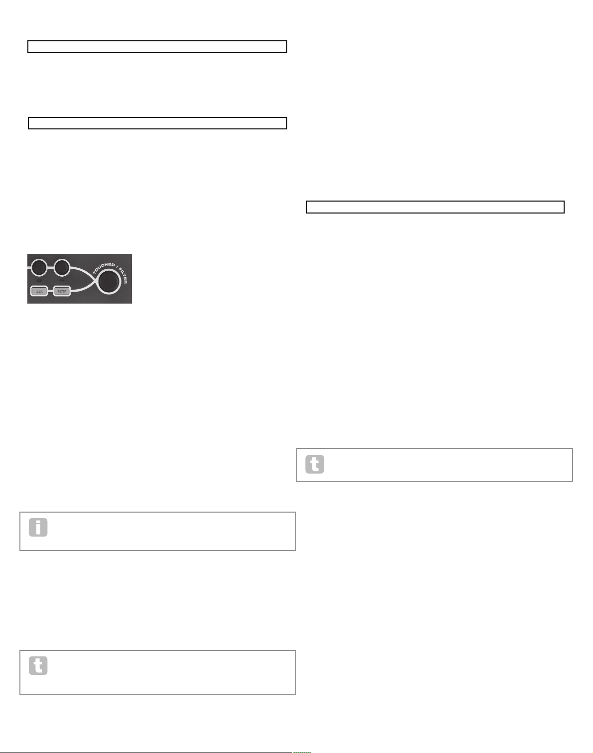
27
Tweak1 Tweak2 Tweak3 Tweak4 Tweak5 Tweak6 Tweak7 Tweak8
Osc1Cents Osc2Cents F1Freq F1Res FltDec L1Rate FX1Amnt FX2Amnt
the arpeggIator
The UltraNova has a powerful Arpeggiator feature which allows arpeggios of varying
complexity and rhythm to be played. If a single key is pressed, the note will be retriggered
by the Arpeggiator. If you play a chord, the Arpeggiator identifies its notes and plays them
individually in sequence (this is termed an arpeggio pattern or “arp sequence”); thus if you
play a C major triad, the selected notes will be C, E and G.
Arpeggiator operation in the UltraNova is controlled by the three ARP buttons [20], ON,
SETTINGS and LATCH. The ON button enables or disables the Arpeggiator, while the
LATCH button plays the currently selected arp sequence repeatedly without the keys being
held. L ATCH can also be pressed before the Arpeggiator is enabled. When the Arpeggiator is enabled, the UltraNova will immediately play the arp sequence defined by the last set
of notes played, and will do so indefinitely.
Editing of all Arpeggiator functions is carried out in the Arpeggiator Menu, which is opened
by pressing the SETTINGS button.
RE1: Arpeggiator Rate Sync
Displayed as: ArpS ync
Initial value: 16th
Range of adjustment: see table at page 40
This parameter effectively determines the beat of the arp sequence, based on the tempo
rate set by RE8.
RE2 : Arpeggiator Mode
Displayed as: ArpM ode
Initial value: Up
Range of adjustment: see table at page 44
When enabled, the Arpeggiator will play all notes held down in a sequence which is determined by the ArpMode parameter. The third column of the table describes the nature of
the sequence in each case.
RE3 : Arpeggiator Pattern
Displayed as: ArpPatt
Initial value: 1
Range of adjustment: 1 to 33
As well as being able to set the basic timing and mode of the arp sequence (with RE1 and
RE2), you can also introduce further rhythmic variations with the Arpeggiator Pattern
parameter.
You should spend some time experimenting with dif ferent combinations of Arp
Mode and Arp Pattern. Some patterns work better in cer tain Modes.
RE4 : Arpeggiator Gate Time
Displayed as: ArpG Tim e
Initial value: 64
Range of adjustment: 1 to 127
This parameter sets the basic duration of the notes played by the Arpeggiator (though this
will be further amended by both the ArpPatt and ArpSync settings). The lower the parameter value, the shorter the duration of the note played. At its maximum value, one note in the
sequence is immediately followed by the next without a gap. At the default value of 64, the
note duration is exactly half the beat interval (as set by R E8 Tempo Clock), and each note
is followed by a rest of equal length.
RE5: Arpeggiator Octaves
Displayed as: ArpO ctve
Initial value: 1
Range of adjustment: 1 to 8
This setting adds upper octaves to the arp sequence. If ArpOctve is set to 2, the sequence
is played as normal, then immediately played again an octave higher. Higher values of ArpOctve extend this process by adding additional higher octaves. ArpOctve values greater
than 1 have the effect of doubling, tripling, etc., the length of the sequence. The additional
notes added duplicate the complete original sequence, but octave-shifted. Thus a four-note
sequence played with ArpOctve set to 1, will consist of eight notes when ArpOctve is set
to 2.
Tweak Menu Page 2:
Each encoder may have any of the available parameters (see list at page 42) assigned to it
for adjustment. Any Tweak Control assignments which form part of a fcatory Patch will be
displayed.
Tweak Menu Page 1:
When a parameter is been assigned to a rotary encoder – either as part of the Patch or
via manual assignment - the upper row shows the parameter name and the lower row the
parameter value, just as they are displayed in their “native” menu.
Note that Tweak and Touch modes are mutually exclusive – the encoders cannot be
assigned to both functions simultaneously, either globally or individually.
Touched/Filter Knob
The large TOUC HED/FILTER knob [9] is a further very useful control in live performance,
particularly if TOUCH or T WEAK functions are being used. It is used in conjunction with
the adjacent buttons FILTER and LOCK [8].
The knob’s function is to mimic that of the last-touched rotar y encoder (this includes
Tweak mode ). This continues to apply even when the currently-open menu or menu page
is changed. Thus if you have the Mix Menu open, and are using RE6 to vary Noise Level,
you will find that you can also vary Noise Level with the Touched/Filter knob. But if you
change to the Filter Menu, the Touched/Filter knob will assume control of Filter 1 Distortion Amount (assuming the Filter Menu opens at Page 1) without any of the rotary encoders
being touched, because it remains assigned to mimic RE6. Think of Touched/ Filter as
a “copy” of the last-touched rotary encoder when you are in parameter adjustment mode,
using the menus as normal.
If you are using either Tweak or Touch modes, then the rotary encoders are no longer available to control any sound parameters in the ‘normal’ way, but you can still control the last
parameter adjusted with the Touched/ Filter knob. This functionality is always available, as
long as both FILTER and LOCK functions [8] are not enabled.
The Filter button
The parameter most often needed for dynamic adjustment is probably Filter 1 frequency,
and pressing the FILTER button [ 8] assigns control of this single parameter to the
Touched /Filter knob (hence its name! ). Thus whatever else is going on, you can always
have control of your main filter frequency.
The TOUCHED/FILTER knob’s function may be given control of Filter 1’s cut-off
frequency permanently, if wished. This can be set up on Page 1 of the Global
Menu with RE6. See page 37 for more details.
The Lock button
As described above, the function of the TOUCHED/FILTER knob will change with the
currently-selected menu, because the knob mimics a physical encoder rather than the
parameter the encoder is currently controlling. If LOCK is active, the parameter currently
being adjusted, and not the physical encoder, is assigned to the knob. Thus if there is a
parameter you want access to continuously, while perhaps retaining access to other parameters in other menus, using LOCK will fix control of that parameter to the TOUCHED/
FILTER knob and it will remain so until LOCK is deselected.
Note that some factory Patches include activation of the LOCK button; this will
be indicated by the button being illuminated. This will mean that a parameter is
already assigned to the TOUCHED/FILTER knob, Try adjusting it to see
what happens !
Osc1Cents Osc2Cents F1Freq F1Res FltDec L1Rate FX1Amnt FX2Amnt
+25 -25 13 45 76 4 64 4
127 0 0 0 0 0 0dB 0dB
Off Off Off Off Off Off
Off Expo 0 Poly1 Off 25
0 Off FadeIn Legato
Off v67 m 0 127 40 HighPass
16th
Up 1 64 1 Off Off 120
28
RE6 : Arpeggiator Key Sync
Displayed as: ArpK Sync
Initial value: Off
Range of adjustment: Off or On
Arpeggiator Key Sync determines how the sequence behaves when an extra note is played.
When Off, the new note is simply added to the sequence at the appropriate point. When
On, the sequence restarts every time a new note is played. Note that ArpKSync only
applies if LATCH [20] is On.
RE7: Arpeggiator Velocity
Displayed as: ArpV el
Initial value: Off
Range of adjustment: Off or On
When set to On, the note velocities used for each note in the arp sequence will be those
pre-programmed with the pattern. When set to Off, the velocities of the notes as you
play them are used by the Arpeggiator. This lets you include dynamics in the Arpeggiator
sequence.
For Arpeggiator Velocity to work, you need to set AmpVeloc (RE5 in Envelope 1
Menu Page 1) to a value greater than 0, otherwise there will be no variation
in dynamics.
Try assigning Velocity to other parameters in the Modulation Matrix for some
interesting results.
RE8: Tempo clock
Displayed as: ClockBPM
Initial value: 120
Range of adjustment: 40 to 250
This parameter sets the tempo in BPM (Beats Per Minute) on which the arp sequence is
based, when using its internal clock . It also defines the Tempo for all synchronised aspects
of the Patch, thus its setting will be used by the various Sync parameters in the FX and
Sync Menus.
IMPORTANT – If the UltraNova is set to receive an external MIDI clock, the ClockBPM
setting will be ignored. Note also that the displayed value for ClockBPM will remain at its last
‘internal’ value if external sync is selected. See page 38 for more details about external sync.
the chorDer
The UltraNova’s Chorder is a very useful feature which permits you to play chords containing up to ten notes by pressing a single key. The resulting chord uses the lowest note
played as its bass; all the other notes in the chord will be above the bass.
The two top panel CHORD buttons control the Chorder [21]; ON simply enables or disables the Chorder function, EDIT opens the Chord Edit Menu.
Programming the chord:
With the Chord Edit Menu open, press the VIEW button [7], (indicated by START on the
display). Its LED will be flashing, but this will go off when the button is pressed, and the
LED in the adjacent USER button (indicated by ACCEPT in the display) will flash instead.
Now play the chord you want to program; you can play it in any key or inversion you wish.
The Chorder will identify the keys being pressed and indicate them in the lower row of the
display, with the lowest note of the chord always showing as a 0. The semitone inter vals
of the other notes in the chord will be shown counting from the left. Thus if you play a flattened seventh chord, the display will show:
Now press the USER key to accept your selection. The chorder function can now be enabled by pressing the ON button. You will find that pressing any key on the keyboard now
plays a flattened seventh chord, with the key pressed forming the lowest note of the chord.
Be aware that the semitone intervals displayed are those from the whole twelve-tone scale,
not those from the eight-note tonic sol-fa usually used to describe the notes comprising a
chord – thus the major third in the example above appears as ‘4’ because it is four
semitones above the root, the natural fifth as ‘7’ because it is 7 semitones above, and so on.
Note that the Arpeggiator precedes the Chorder within the UltraNova’s synth
engine. This has the consequence that if both the Arpeggiator and Chorder are in
use, the entire chord resulting from each key press will be arpeggiated.
RE1: Transposition control
Displayed as: Transpose
Initial value: 0
Range of adjustment: -11 to +11
The transposition control is calibrated in semitone intervals, and the pitch of the chord can
be shif ted up to 11 semitones, either up or down.
RE2 to RE8: Not used.
effectS (fx)
The UltraNova comes equipped with a comprehensive set of DSP-based effects
processors, which can be applied to both the synth sound and any audio applied to the
UltraNova’s audio inputs.
The FX section comprises five processing “slots”, each of which may be “loaded” with an
FX processor from a pool of devices that includes panning, equalisation, compression,
delay, chorus, distortion, reverb and Gator effects. In addition to the slots, controls are also
provided for global FX parameters like panning, FX level, FX feedback, etc.
The FX Menus are opened with the EFFECT button [18]. Either three or four menu pages
are available, depending whether any slots have been loaded with FX devices. The first
three pages provide controls for panning, FX levels, FX device selection and device routing, and are constant. The fourth page is the control page for the processing slot currently
selected by the SELEC T buttons [10], so if multiple slots are in use, then additional menu
pages can be accessed by using the SELECT buttons.
FX Menu Page 1 – Panning
RE1: not used.
RE2 Pan c ontrol
Displayed as: PanPos n
Initial value: 0
Range of adjustment: -64 to +63
This is the main manual pan control and positions the dr y (pre-FX) synth sound/Input audio
in the stereo image between outputs 1 and 2, and also between outputs 3 and 4, if they are
in use. Negative values of PanPosn move the sound to the left and positive values to the
right. Note that some FX (e.g. reverb, chorus ) are inherently stereo, and these are added
post-panning. Thus if you are using a sound that uses FX such as these, PanPosn will appear to not entirely localise the sound fully left or right at its extreme settings.
RE3 : Pan Rate
Displayed as: PanRat e
Initial value: 40
Range of adjustment: 0 to 127
Automatic panning is also possible, and the Pan section has a dedicated sinewave LFO
which controls this. The PanRate parameter controls the LFO frequency, and thus how
rapidly the sound moves between left and right and back again. With a value of 40, the
sound takes approx. 3 seconds to complete a full cycle, and the range of control allows
extremely slow or extremely fast panning.
For the most effective results with Pan Rate, ensure that PanPosn is set 0 (i.e.
centre panning)
RE4 : Pan Rate Sync
Displayed as: PanSy nc
Initial value: Off
Range of adjustment: see table at page 40
Auto-panning rate may synchronised to the internal or external MIDI clock, using a wide
variety of tempos.
127 0 0 0 0 0 0dB 0dB
Off Off Off Off Off Off
Off Expo 0 Poly1 Off 25
0 Off FadeIn Legato
Off v67 m 0 127 40 HighPass
Transpose ^^ ^^ Bass I1 I2 I3 I4 I5 I6 I7 I8 I9
0 START ACCEPT - - - - - - - - - -
Transpose ^^ ^^ Bass I1 I2 I3 I4 I5 I6 I7 I8 I9
0 START ACCEPT 0 4 7 10 - - - - - -
127 0 0 0 0 0 0dB 0dB
Off Off Off Off Off Off
Off Expo 0 Poly1 Off 25
0 Off FadeIn Legato
Off v67 m 0 127 40 HighPass
Transpose ^^ ^^ Bass I1 I2 I3 I4 I5 I6 I7 I8 I9
0 START ACCEPT - - - - - - - - - -
Number Source1 Source2 TouchSel Destin Depth
1 Direct Direct Off O123Ptch 0
PAN PanPosn PanRate PanSync PanDepth
0 40 Off 0
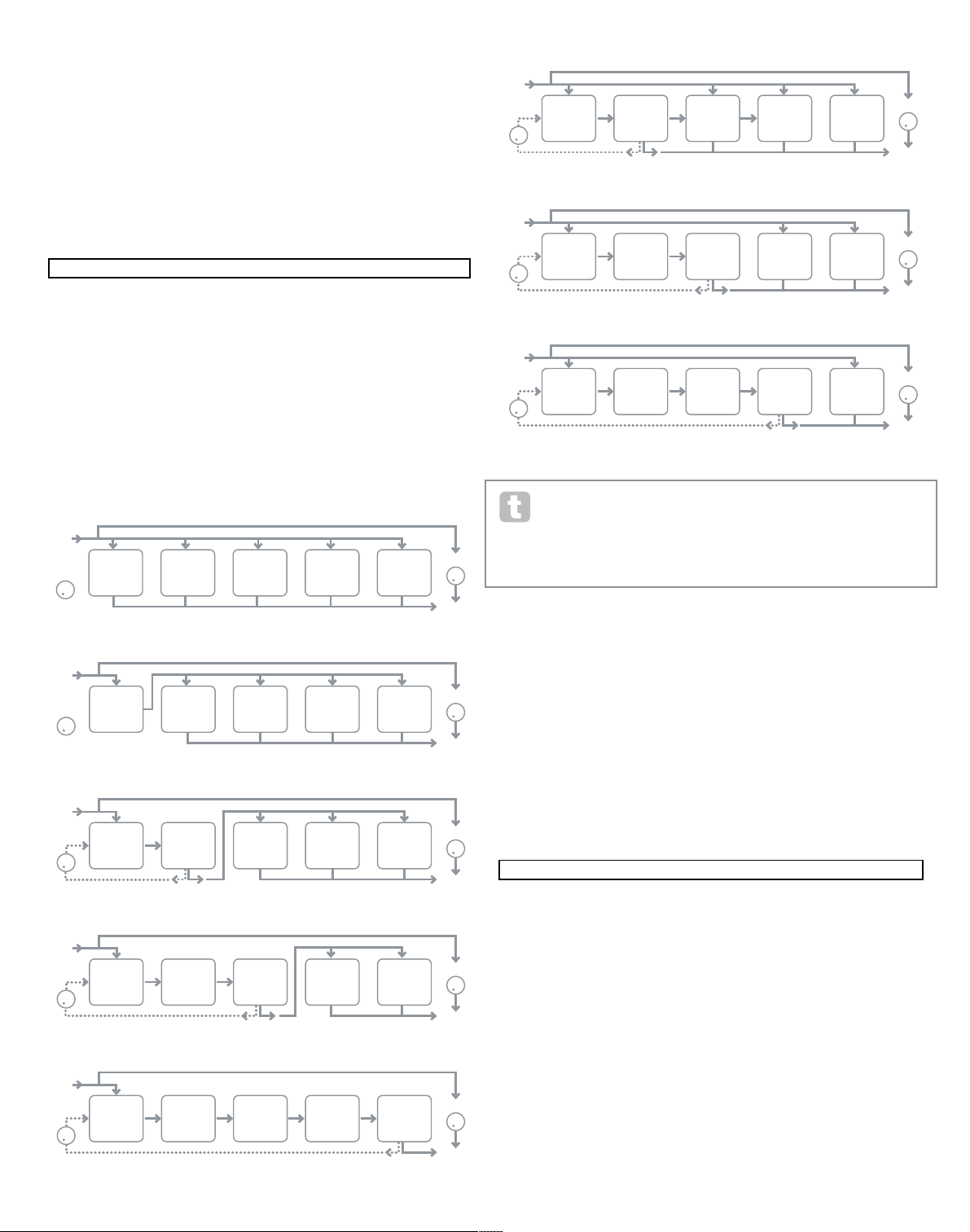
29
RE5: Pan Depth
Displayed as: PanDe pth
Initial value: 0
Range of adjustment: 0 to 127
This control determines the amount of image shift applied by the auto-panner. At its
maximum value of 127, the auto-panner will pan the sound both fully left and fully right;
lower values will pan less extremely, with the sound remaining more centrally located. The
auto-panner is effectively off when the parameter value is zero (but the manual pan control
RE2 is still operative).
RE6 to RE8: Not used.
FX Menu Page 2 – Routing
This menu page is where you assign the effects you need. You can also specify their configuration – whether they are “connected” serially, with the output of one feeding the input
of another, or are in parallel, where the synth sound is fed to the inputs of more than one FX
device simultaneously, the device outputs then being mixed together.
RE1: FX Slot routing
Displayed as: Routing
Initial value: 1(2+3+4+5)
Range of adjustment: see diagrams below
This parameter lets you configure the interconnection of the FX slots. The five slots may be
interconnected in serial, in parallel, or in various combinations of serial and parallel.
The FX types can be categorised in various ways: some are time-based (chorus,
delay), others are static (EQ, distortion). Some should be used as an F X send /
return loop (implying a parallel connection), others as an insert (implying a serial
connection). Depending on the synth sound itself and the actual effects being used, some
configurations will clearly work better than others. When using multiple effects, try a few
different interconnections to see which works best.
RE2 : Not used.
RE3 to RE7: Slot Effec t Selection
Displayed as: SlotnFX (where n=1 to 5)
Initial value: Bypass
Range of adjustment: see table at page 44
Each of the five slots may be loaded with one of the available FX processors. Use the rotary
encoder for any slot to select an ef fect from the list of those available. The table shows the
“pool” of FX devices available. As DSP capacity is finite, each device in the list may only be
loaded into one slot, and once it has been loaded, it will no longer appear in the list of available processors for the other slots. You will see that multiples of most of the F X devices are
provided, to allow the most creative use of the FX.
RE8: Not used.
FX Menu Page 3 – FX Level controls
RE1: Effect feedback
Displayed as: FXFedb ck
Initial value: 0
Range of adjustment: 0 to 127
This parameter controls how much signal is fed back to the input of the effects chain from
its output. The FX Slot from which the feedback is derived varies with the FX Routing
configuration in use – see diagram. However, with all routing configurations, the feedback
is added back into the chain at FX Slot 1. Note that not all configurations employ feedback.
RE2 Not used.
127 0 0 0 0 0 0dB 0dB
Off Off Off Off Off Off
Off Expo 0 Poly1 Off 25
0 Off FadeIn Legato
Off v67 m 0 127 40 HighPass
Transpose ^^ ^^ Bass I1 I2 I3 I4 I5 I6 I7 I8 I9
0 START ACCEPT - - - - - - - - - -
Number Source1 Source2 TouchSel Destin Depth
1 Direct Direct Off O123Ptch 0
0 40 Off 0
Routing Slot1FX Slot2FX Slot3FX Slot4FX Slot5FX
1>(2+3+4+5) Bypass Bypass Bypass Bypass Bypass
DRY/WET
OUTPUT
FEEDBACK
(DISABLED)
INPUT
SLOT
1
SLOT
2
SLOT
3
SLOT
4
SLOT
5
DRY/WET
OUTPUT
FEEDBACK
INPUT
SLOT
1
SLOT
2
SLOT
3
SLOT
4
SLOT
5
DRY/WET
OUTPUT
FEEDBACK
INPUT
SLOT
1
SLOT
2
SLOT
3
SLOT
4
SLOT
5
DRY/WET
OUTPUT
FEEDBACK
INPUT
SLOT
1
SLOT
2
SLOT
3
SLOT
4
SLOT
5
DRY/WET
OUTPUT
FEEDBACK
INPUT
SLOT
1
SLOT
2
SLOT
3
SLOT
4
SLOT
5
DRY/WET
OUTPUT
FEEDBACK
INPUT
SLOT
1
SLOT
2
SLOT
3
SLOT
4
SLOT
5
DRY/WET
OUTPUT
FEEDBACK
INPUT
SLOT
1
SLOT
2
SLOT
3
SLOT
4
SLOT
5
DRY/WET
OUTPUT
FEEDBACK
INPUT
SLOT
1
SLOT
2
SLOT
3
SLOT
4
SLOT
5
1>(2+3+4+5)
1>2>(3+4+5)
1>2>3(4+5)
1>2 + 3+4+5
1>2>3>4>5
1>2>3 + 4+5
1+2+3+4+5
1>2>3>4 + 5
FXFedbck FX1Amnt FX2Amnt FX3Amnt FX4Amnt FX5Amnt FXWetLvl
0 64 64 64 64 64 0
 Loading...