

Page 1

Copyright: Novation E.M.S Limited 2003 ReMOTE User Guide
Version 1.5
Features and specifications subject to change without notice due
to improvements
www.novationmusic.com
Page 2

CONTENTS
Contents
• 1 •
Introduction............................................................................................
Using This Manual..................................................................................
Main Features.........................................................................................
Conventions Used In This Manual..........................................................
Quick Start Guide...................................................................................
Getting Started - Connecting Up to equipment using MIDI....................
Power Supply and Battery Operation.....................................................
Connecting to a Computer System using USB.......................................
Installing the USB driver Software..........................................................
Connecting to a Computer Using the USB Port.....................................
Connecting to MIDI and a Computer using the USB port.......................
Using Preset Template labels.................................................................
Using Programmable Template Controls................................................
Sending a Snapshot of the Controls.......................................................
Selecting a Sound on External MIDI devices.........................................
Changing the action of the Pitch / Modulation Joystick..........................
MIDI Tutorial............................................................................................
Introduction.............................................................................................
How MIDI Ports Are Used.......................................................................
MIDI Messages.......................................................................................
Main Features And Operation...............................................................
Front Panel Layout..................................................................................
Modes And Menus..................................................................................
Using Menus...........................................................................................
The Template Select Mode Menu...........................................................
The Template Edit Mode Menu (Editing A Template).............................
The Template Edit ‘CC’ Pages................................................................
The Template Edit ‘NRPN’ Pages...........................................................
The Template Edit ‘RPN’ Pages.............................................................
The Template Edit ‘MMC’ Pages............................................................
The Template Edit ‘Note On/Off’ Pages..................................................
The Template Edit ‘SYSEX MESSAGE’ Pages......................................
The Template Edit ‘Program Change’ Pages.........................................
Using The X/Y Touchpad........................................................................
Using The Footswitch & Pedal................................................................
Saving A Template To Memory...............................................................
Advanced Features................................................................................
Using The Transport Buttons..................................................................
The Global Mode Menu..........................................................................
Saving The Global Settings To Memory.............................................. ...
Updating The Operating System............................................................
Troubleshooting.....................................................................................
Appendix.................................................................................................
Using the ReMOTE with Reason............................................................
MIDI Implementation Chart.....................................................................
Control Summary....................................................................................
Preset Template Listing...........................................................................
Approvals Information.............................................................................
2
2
2
3
4
4
5
6
6
8
9
10
13
14
15
15
16
16
16
17
21
21
22
23
25
27
28
30
31
32
33
34
36
37
39
40
42
42
43
47
48
49
50
50
51
52
56
60
Page 3

INTRODUCTION
Using This Manual - Main Features
• 2 •
Thank you for purchasing the Novation ReMOTE 25 controller keyboard. This device may be used to control sequencers, popular software virtual instrument applications on a computer or traditional hardware
instruments via either a USB connection or a standard MIDI interface. The ReMOTE 25 front panel provides a wealth of programmable controls, each of which can be configured to exactly suit your needs and
stored within a Template memory for later instant recall.
The ReMOTE 25 is equally at home in a live performance situation where it can be used as a stand-alone
MIDI controller keyboard. Whether used live or in the studio to control virtual instruments, its comprehensive range of controls may be used to dynamically alter any sound parameters precisely and in real time.
Using This Manual
This manual consists of six sections; Introduction, Quick Start Guide, MIDI Tutorial, Main Features and
Operation, Troubleshooting and Advanced Features. For easy reference, the section name is printed at
the top of each page. An Appendix is also provided containing reference data.
It is assumed that the reader already has a basic knowledge of MIDI in order to configure user Templates.
Those with limited MIDI experience may find the MIDI Tutorial useful. Very little MIDI knowledge is
required to use the the ReMOTE with the factory programmed Templates.
In order to become familiar with the many useful features of the ReMOTE 25 and get the most out of its
powerful MIDI controlling possibilities, it is recommended that this manual is read in sequence chapter by
chapter. For those who wish to start straight away, the Quick Start Guide provides information on setting
up the ReMOTE 25 and a quick overview on selecting and using Preset Templates.
Have fun !
Main Features
* Two octave semi-weighted velocity-sensitive keyboard with combined Pitch bend and Modulation
joystick. The keyboard is transposable up or down across the entire MIDI note range and can
transmit Channel Aftertouch.
* MIDI or USB operation. USB and MIDI may be used simultaneously. Two MIDI OUT ports, a
MIDI IN Port, a Foot pedal input socket and a Footswitch input socket are available.
* Can be powered by the USB port, Batteries or a 9v DC adaptor (not supplied).
* Generous selection of front panel controls including an X-Y touchpad, 8 knobs, 8 rotary
encoders, 8 sliders and 24 MIDI control buttons, all of which can be individually configured.
* Comprehensive MIDI specification. Any front panel control may be configured to transmit on any
MIDI channel, to any destination. Available options include Controller numbers, NRPNs, RPNS,
Bank Change, Program Change and definable System Exclusive Strings.
* System Exclusive strings may be up to 20 bytes long. Front panel control data may be inserted
anywhere within the System Exclusive message.
* 64 Template editable memories available. Each Template contains definitions for all front panel
controls. Templates may be individually named for easy reference.
* Template memories may be saved as a System Exclusive bulk dumps to an External sequencer
or MIDI data filer.
Page 4

INTRODUCTION
Conventions Used In This Manual
• 3 •
Conventions Used In This Manual
The word ‘Template’ refers to a collection of knobs, encoders and button settings and the function of the
footswitch, pedal and X-Y touchpad. Each Template is numbered from 1 to 64 and can be saved in the
ReMOTE 25’s non-volatile memory.
The word ‘Template Label’ refers to a collection of three coloured or blank ‘overlays’ which sit neatly in the
three recesses on the front panel of the ReMOTE 25. Each one of these Template Label sets is used in
conjunction with a template as described above.
The word ‘Preset’ refers to a Template configured at the factory to showcase some of the ReMOTE 25’s
powerful control possibilities. Preset Templates may be over-written by new settings.
The word ‘Control’ refers to any of the front panel knobs, assignable buttons, encoders, footswitch, foot
pedal, joystick or the X-Y touchpad. Within a single Template, each control may be individually configured
to transmit various types of MIDI information addressed on any combination of the MIDI OUT / USB ports.
The word ‘Setting’ refers to any parameter which is edited from within a menu.
Text in CAPITALS refers to a front panel Control or legend (even though the name of the Control may actually be in lower case on the front panel). It could be a knob, button, slider or rotary encoder.
Page 5
QUICK START GUIDE
Getting Started - Connecting Up to equipment using MIDI
• 4 •
Getting Started - Connecting Up
The ReMOTE 25 may be connected to a system in three different ways
1 Connection to equipment using the MIDI In and Out Jacks.
2 Connection to a Computer system using the USB port.
3 Connection to equipment using MIDI In and Out AND to a computer
using the USB port.
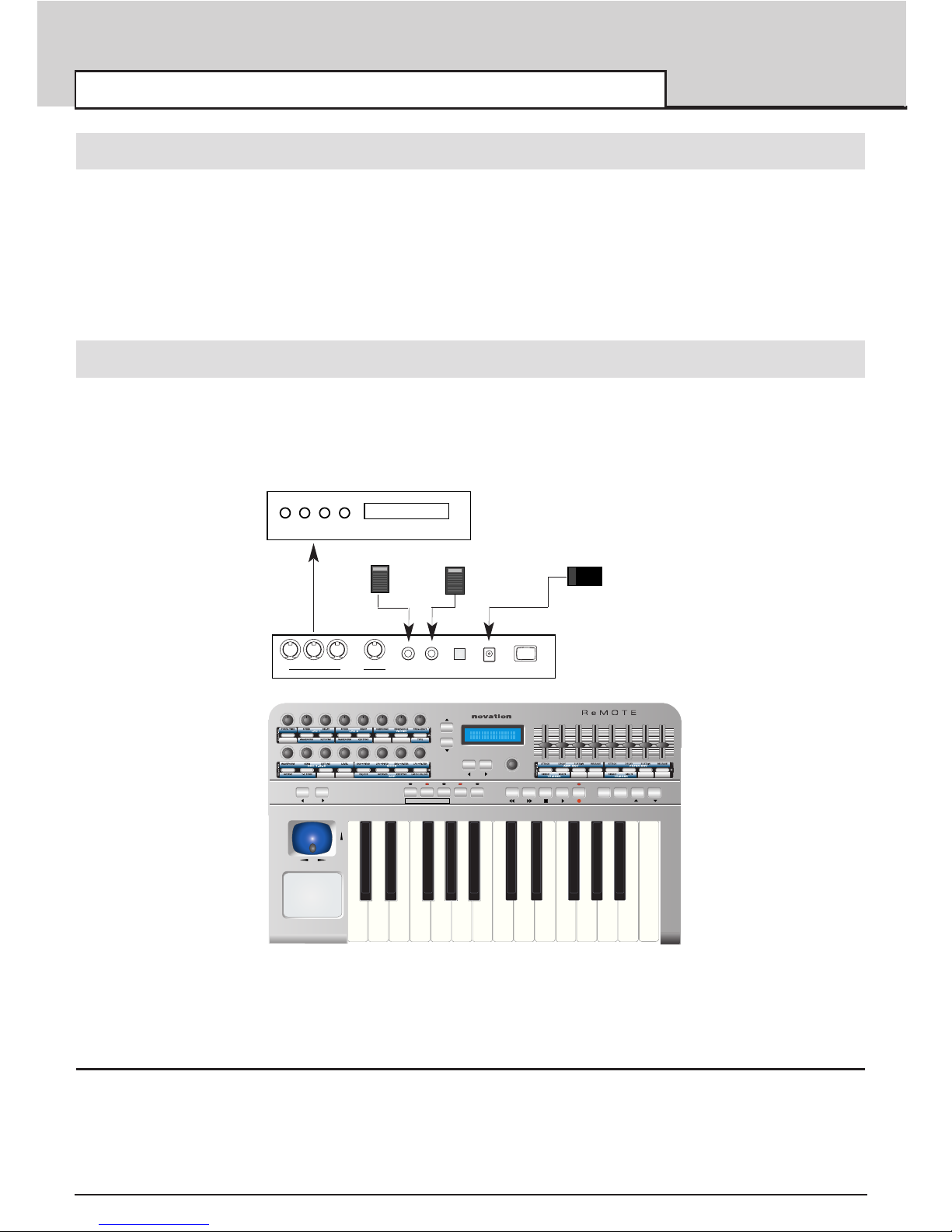
1 Connection to equipment using the MIDI In and Out Jacks
This is referred to as the ‘stand alone’ or ‘live’ set-up. The illustration below shows a typical arrangement.
Ensure power is off on all equipment. Connect the MIDI out of the ReMOTE 25 to the MIDI in of a suitable
sound module.
If batteries are not fitted then an external power supply (Novation PSU6) must be connected - See next
page for battery information. Connect any other devices such as pedals to the ReMOTE 25. Switch on the
power to all devices.
Playing the Sound Module from the ReMOTE 25
Set the receiving MIDI channel of the sound module to Channel 1 or OMNI (this should be the default).
The keyboard and pitch/modulation joystick will be active and the sound module will respond to the MIDI
information being sent from the ReMOTE 25. If the sound module conforms to General MIDI then locate
the General MIDI template labels and place them in the three template recesses (See page 10).
pitch
mod
data / value
value cc# midi chan midi port
prog / page
writeselect snapshot panic templateedittemplate play
octave
cursor
F1 F2 F3 F4
global
2 5
Expression Pedal
Sustain Pedal
Novation PSU6
Power supply
thru
MIDI port 1 MIDI port 2
off / on9 Volt D.C in
Power
out outin
sustain
pedal
expression
pedal
USB
O I
MIDI In
Sound
Module
ReMOTE 25
rear panel
External Power Supply need
not be used if batteries are
fitted - see following section
‘Power Supply or Battery
Operation’.
Page 6
QUICK START GUIDE
Power Supply and Battery Operation - Connecting to a Computer System
• 5 •
Press the TEMPLATE SELECT mode button and select template No. 49 ‘General MIDI 2’ using the
data/encoder knob below the display. Press the PLAY mode button. Moving the controls as indicated by
the template label will send the corresponding information to the sound module.
If the sound module does not conform to General MIDI it may be listed in the factory preset template list in
the Appendix, if so, press the TEMPLATE SELECT button and using the data / encoder knob below the
display, scroll through the list until the correct template is located. The template may also have a set of
pre-printed labels (See Appendix), if so, fit as described on page 10. Press the PLAY mode button.
Power Supply or Battery operation
The ReMOTE 25 may be powered by an external Power Supply (Novation PSU6) or by batteries. It will
run on all types of ‘C’ size dry or re-chargeable cells.
Battery T
ype ReChargeable ? Approx Operating T
ime Comments
Nicad Yes 16 Hours Standard Rechargeable Cells
Alkaline No 32 Hours Normal High Power Dry Cells
Duracell No 64 Hours Extra High Power Long life Dry
Cells
The ReMOTE 25 will automatically sense the battery type and calculate charging rate depending on the
condition of the battery.
Fitting Batteries
Turn the ReMOTE 25 upside down and unclip the battery compartment using two fingers to push on the
clips. Observe the connection diagram imprinted on the plastic casing for 6 x ‘C’ cells to the right of the
battery cover. Fit the cells as shown in the diagram.
Power Operation
The ReMOTE 25 may be configured to charge or not charge the batteries (if rechargeable's have been fitted) from either the USB port, the external power supply or both. - See page 46 in the global menu for
details.
Laptop Operation
When using a USB connection to power the ReMOTE from a Laptop computer the ReMOTE may not
power up successfully. This is due to the ReMOTE not being able to draw enough power from the Laptop
computer.
The ReMOTE requires approx 250mA of current to run properly. Some Laptops are not able to supply this
much current from the USB socket.
The solution is to either :
1 Power the ReMOTE from a suitable AC:DC power adaptor (such as Novation PSU6) or
2 Insert Dry or (recommended) insert rechargeable batteries.
When rechargeable batteries are fitted an option in the GLOBAL menu may be used to set the charge rate
for the batteries.
If set to trickle charge the loading on the USB socket at the Laptop will only be 75mA. If set to Max charge
the loading will be 150mA.
Page 7

2 Connecting to a Computer System using the USB port
The ReMOTE 25 has a USB connector located on the rear panel. When using the USB cable supplied it
can be used to directly communicate with PCs that have also have USB connector (commonly known as a
‘Port’). Before it can communicate with the PC’s USB port, a special piece of software known as a ‘
USB
driver’ must be installed.
This USB driver software converts information arriving at the computer’s USB port into the correct format
for use by the software MIDI interface used by the windows system. Most music application software
(Cubase, Logic, Cakewalk Sonar etc) uses this software MIDI interface to communicate with external hardware devices such as the ReMOTE 25 or other keyboards and sound modules.
The USB driver software is located on the CD ROM supplied. It is suitable for the Windows 98 SE
(Second edition), 98 ME (Millennium edition) 2000 or XP operating systems. If using a PC with a differ-
ent operating system such as Linux or Windows 95, USB support will not be available and a standard
MIDI interface must be used for communication between the computer and the ReMOTE 25.
Installing The USB Driver Software
Turn on the computer and allow it to finish ‘booting up’. Plug in one end of the USB cable supplied to one
of the computer’s USB sockets. It is not possible to connect this incorrectly since only one end will fit the
computer’s USB socket. Connect the other end to the ReMOTE 25’s USB socket on the rear panel.
Turn on the power to the ReMOTE25. It is not necessary to have batteries or an external PSU connected
since power is drawn from the computer via the USB cable. Skip to the section below relevant to the operating system that is being used.
Windows 98 SE ( Second Edition ) Installation
A dialogue box titled 'add new hardware wizard' will appear. The box will inform: 'This Wizard searches for
new drivers for ReMOTE 25.
Click 'Next'. A dialogue box will inform: 'search for the best driver for your device (recommended)' already
optioned. Click 'next'.
Insert the Novation driver CD into the CD-ROM drive of the computer. Tick the 'CD-ROM' option and 'specify location' option. In the space below 'specify location' Type in the drive letter appropriate for your CDROM drive letter followed by a colon. This drive is normally D: (be sure to include the colon) Click
'Browse'.
A dialogue box will appear. Locate and select the folder 'Win98SE'. Click 'OK'. Click 'Next'
The next box informs that the ReMote 25 has been located on the CD. The location of the driver will be
D:\WIN98SE\\NVN98SE.INF (where D is the CD-ROM drive letter) click 'next'
A prompt may be made to insert the Windows 98 Second Edition CD. If not proceed to the next paragraph.
This CD will have been supplied with the computer. Remove the Novation driver disk and Insert the
Windows CD. Browse the CD and click on the Win98 folder. Click 'OK'. A 'copying files' dialogue box will
appear for a short time.
A final box appears informing 'Windows has finished installing the software that your new hardware device
requires'. A Reference to the ReMOTE 25 will be made. Click 'finish'.
Shutdown and restart the computer. After restarting a 'Add New Hardware Wizard' may appear. If so press
'cancel'.
The Remote 25 is now ready for use with the computer. Go to the next section of this manual titled
'Selecting the ReMOTE 25 USB MIDI interface within Music Applications'. Page 7
Windows 98 ME ( Millennium Edition) Installation
A dialogue box titled 'add new hardware wizard' will appear. It will inform that 'windows has found new
QUICK START GUIDE
Installing The USB Driver Software
• 6 •
Page 8

QUICK START GUIDE
Installing The USB Driver Software
• 7 •
hardware' - ReMOTE 25 The circle 'Automatic search for a better driver (recommended)' is already
optioned.
Insert the Novation driver CD into the computer's CD drive and click 'next'.
A dialogue box will appear which will state 'Windows has found more than one driver that may work for
your hardware. Please select the driver that matches your language and device.' Click (select) the
ReMOTE25 line that shows D:\WINXPME\NVNXPME1.INF. Click 'OK'.
A new 'add new hardware wizard' will appear and it will inform that 'windows has finished installing a new
hardware device'. ReMOTE 25 with a small icon will also appear in the dialogue box. Click ' finish'.
The Remote 25 is now ready for use. Go to the next section of this manual titled 'Selecting the ReMOTE
25 USB MIDI interface within Music Applications'.
Windows 2000 Installation
A 'Found New Hardware Wizard' dialogue box appears titled 'Welcome to the found new hardware Wizard'.
Click 'next'. A new dialogue box will appear titled 'Install Hardware Device Drivers' and the circle 'Search
for a suitable driver for my device (recommended)' will be optioned. Click 'next'.
Insert the Novation driver CD into the CD-ROM drive of the computer.
A dialogue box appears titled 'Locate Driver Files' Tick the box 'CD-ROM drives'. (Ensure no other boxes
are ticked). Click 'Next'.
A box appears titled 'Driver Files Search Results'. The ReMOTE 25 name will appear in the dialogue box
along with the driver name 'D:\winxpme\winxpme1.inf INF '(where D is the CD-ROM drive letter) Click
'next'
The box titled 'Digital Signature Not Found' will appear. This informs that there is no Microsoft Digital signature. At the prompt 'Do you want to continue with the installation ?'. Click 'Yes'. A final box appears
titled 'Completing the Found New Hardware Wizard'. Click 'Finish'.
Windows will now prompt to restart the computer. It must be restarted in order for the driver to become
active. The Remote 25 is now ready for use with the computer. Go the next section of this manual titled
'Selecting the ReMOTE 25 USB MIDI interface within Music Applications'.
Windows XP Installation
Insert the Novation driver CD into the CD-ROM drive of the computer. A small balloon may pop up for a
short time in the corner of the taskbar (depending on Windows XP settings) and a dialogue box will open
on titled ‘Found New Hardware Wizard’. Two choices are presented. Select auto install.
The next screen will inform that the USB logo has not been tested by Microsoft. Click ‘Continue Anyway’
Do not be alarmed by the message since the driver has been tested.
Windows will now confirm that the installation is complete. Click the ‘Finish’ button.
Selecting the RemOTE 25 USB MIDI interface within Music Applications
It is most likely that the ReMOTE 25 will be used with a Music Software sequencer package such as
Cubase, Logic, Cakewalk Sonar etc. The USB driver software just installed will allow the ReMOTE 25 to
be seen by the computer as a MIDI device.
Before the ReMOTE 25 will be recognised by the sequencer or software package the ReMOTE 25 MIDI
port must be selected in the application.
Consult the documentation supplied with the software package on how to do this.
Once selected (and as long as the power is on) pressing a key on the ReMOTE 25 will result in incoming
MIDI activity.
Page 9
QUICK START GUIDE
Connecting to a Computer Using the USB Port
• 8 •
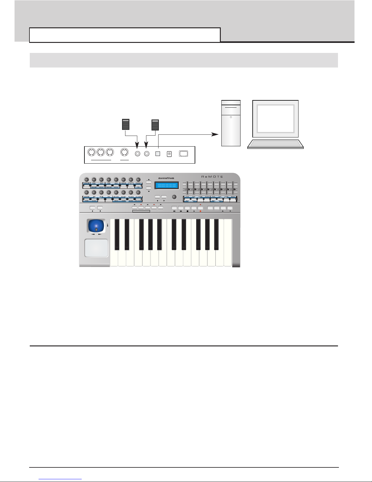
2 Connection to a Computer System using the USB Port
The illustration below shows a typical arrangement. - note the simplicity! The USB cable will already be
connected. Connect expression and sustain pedals if required.
Since power is being supplied from the computer via the USB cable it is not necessary to have batteries or
an external PSU fitted.
Playing Software Synthesizers from the ReMOTE 25
Numerous software synthesizers may be played from the ReMOTE 25. To make this straightforward,
Templates in the form of memories that contain the specific control information for each synthesizer are
preset in the ReMOTE 25.
When shipped from the factory there are over 50 template memories preprogrammed and many have sets
of template overlay labels to allow ease of use. See page 10 for more details on templates.
pitch
mod
data / value
value cc# midi chan midi port
prog / page
writeselect snapshot panic templateedittemplate play
octave
cursor
F1 F2 F3 F4
global
2 5
Expression Pedal
Sustain Pedal
thru
MIDI port 1 MIDI port 2
off / on9 Volt D.C in
Power
out outin
sustain
pedal
expression
pedal
USB
O I
ReMOTE 25
Rear Panel
Page 10
QUICK START GUIDE
Connecting to MIDI and a Computer using the USB port
• 9 •
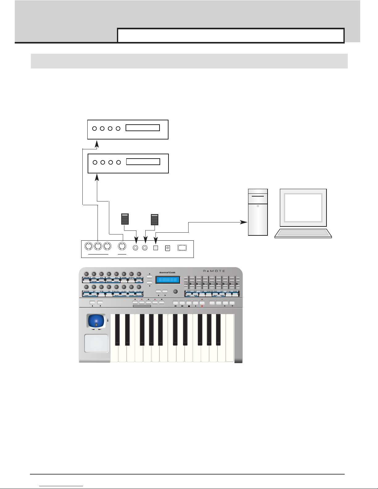
3 Connecting to equipment using MIDI In and Out AND connecting to a computer using the USB port
This is an advanced setup where the ReMOTE 25 is connected to two external sound modules using both
the MIDI 1 and MIDI 2 ports as well as being connected to a computer via USB.
This setup provides a very flexible system. Two separate MIDI ports are used for controlling the sound modules which gives 32 channels of available MIDI (2 x 16 channels). The MIDI data sent from the computer via
the USB port can control the sound modules as well events (such as slider or knob movements and key
presses) from the ReMOTE 25.
The ReMOTE 25 can also simultaneously control the sequencer and any software synths or samplers running within the computer.
pitch
mod
data / value
value cc# midi chan midi port
prog / page
writeselect snapshot panic templateedittemplate play
octave
cursor
F1 F2 F3 F4
global
2 5
Expression Pedal
Sustain Pedal
thru
MIDI port 1 MIDI port 2
off / on9 Volt D.C in
Power
out outin
sustain
pedal
expression
pedal
USB
O I
MIDI In
MIDI In
Sound
Module 1
Sound
Module 2
ReMOTE 25
Rear Panel
Page 11
• 10 •
Using Preset template Labels
A total of twenty sets of template labels are supplied with the ReMOTE 25. Seventeen sets are preprinted
for use with popular software and hardware devices and three sets are blank which can be customised
(written, using a pen or pencil) for use with any setup - For a complete list, see the Appendix.
Very often a piece of equipment such as a complex software or hardware synthesizer has many more controls than is available on the ReMOTE 25’s front panel at any one time. The ReMOTE 25 allows such
equipment to be controlled by using a collection of Template memories and just a single set of template
labels.
This is best illustrated using an example of setting up the ReMOTE to control a software synthesizer that
has more than the number of controls on the front panel.
It is recommended that the following paragraphs are read carefully and the actions are carried out to
understand how the ReMOTE can control equipment with many many controls.
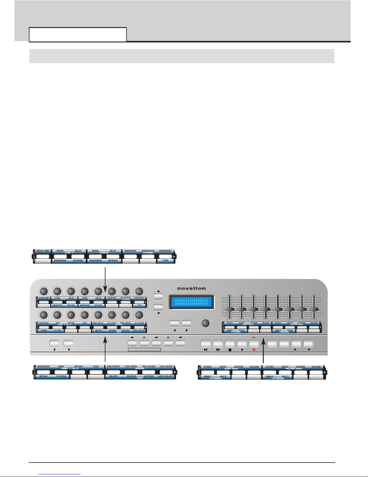
Locate the template label set titled ‘VA Synth’ as illustrated and notice that each template has a letter A, B
or C to the right hand side.
Slip the template labels into the recesses on the front panel as shown below noting the locations as
defined by the letters A, B and C.
Using Preset Templates
QUICK START GUIDE
data / value
value cc# midi chan midi port
prog / page
writeselect snapshot panic templateedittemplate play
octave
cursor
F1 F2 F3 F4
global
A
B
C
Page 12
• 11 •
Study the VA Synth template label set (they are marked A B and C at the right hand end) and notice that
controls are grouped in a logical sequence. For example on template B the first four text names in black
are
WAVEFORM SEMI DETUNE LEVEL
and they are in a blue shaded group with white text that says;
OSC 1..2..3
It is this logical sequence that allows the rapid editing of more controls than are available on the ReMOTE
25’s panel.
The concept is best understood by following the example of controlling the Novation V Station software
synthesizer. ( It is not necessary to have this software in order to understand the concept)
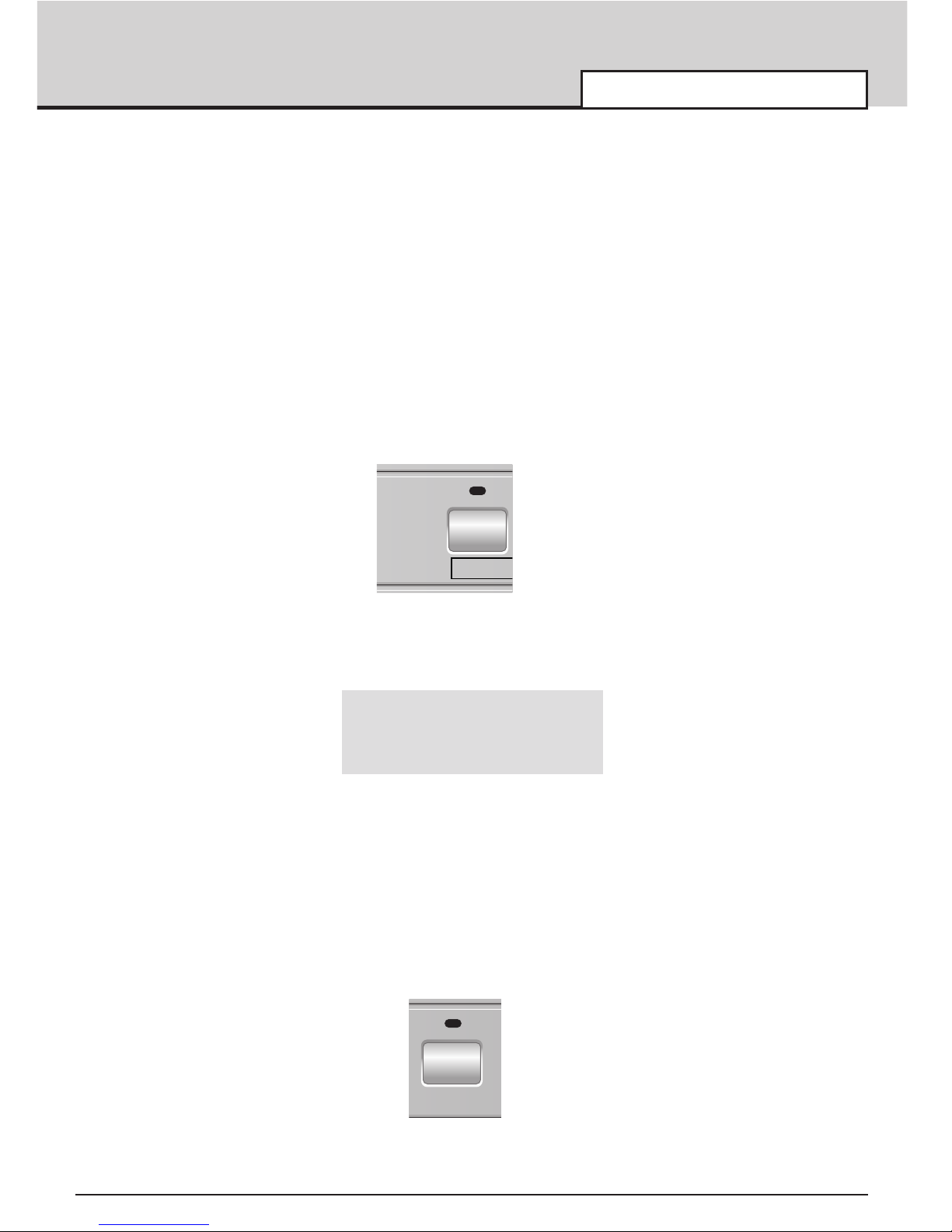
Template memories are selected in Template Select Mode. To enter Template Select Mode, press the
TEMPLATE SELECT button.
The button LED will light confirming that Template Select Mode is active. The screen will show the name
and number of the currently selected Template for example,
Novation 1
V-Station
Rotate the encoder below the display to view the templates available. The display will typically show the
manufacturer’s name on the top line and the model name on the lower line. The template memory number
(from 1 to 64) is shown on the top right. Notice that for some of the equipment names there is often more
than one template memory.
It is this grouping of more than one template memory that allows for fast editing of numerous controls.
There are three such template memories, 1 2 and 3, for the Novation V Station. Locate template No. 1 V
Station as shown above. Play Mode must be selected to view the realtime values of any control being
moved. Play Mode is selected by pressing the PLAY button.
The LED above the button lights to indicate when Play Mode is activated.
Using Preset Templates
QUICK START GUIDE
selecttemplate
play
Page 13
• 12 •
QUICK START GUIDE
Using Preset Templates
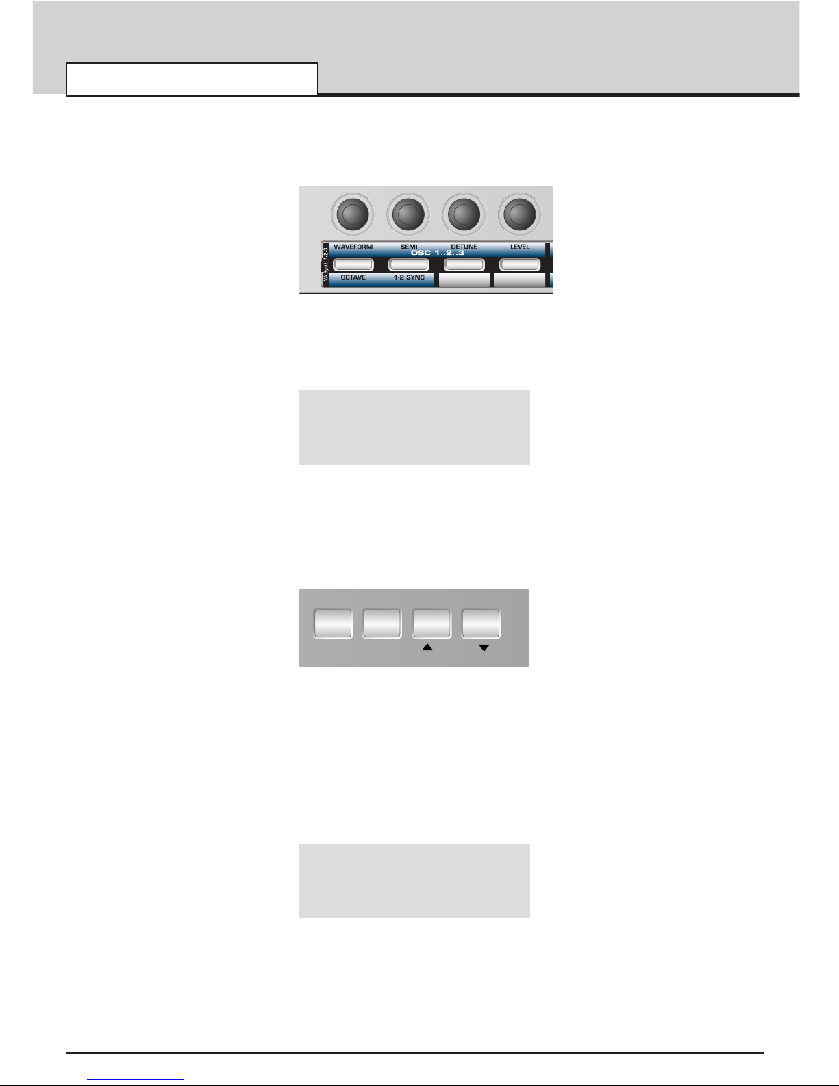
Rotate any of the first four encoders as shown in the illustration and notice how the realtime values of the
controls are displayed.
Rotate the first encoder and the display will appear similar to illustration below.
Osc 1 Waveform
2 CC70 1 U12
The V Station sofware synthesizer has three sets of oscillators OSC 1 OSC 2 and OSC 3. The current
template memory (V Station 1) only allows access to the first oscillators, (OSC 1) controls.
Function keys F1, F2, F3 and F4 are shown below
When shipped from the factory function keys F3 and F4 act as quick ‘template up’ or ‘template down’
select buttons when in Play Mode. The operation of these Function keys may be changed in the Global
Menu - See pages 43 and 44.
To select the next set of Oscillator controls, simply press the F3 button once to select the next template
memory of the V Station. This is titled V Station 2.
Rotate the first encoder again and the display will appear similar to one below,
Osc 2 Waveform
1 CC70 1 U12
It is by using the F3 and F4 keys in this way that allows very fast access to numerous controls of
any equipment.
Alternatively, template select mode may be entered and the encoder rotated to select the next or
previous template memory. A full list of template and specific notes for each template is listed in the
Appendix.
snapshot panic template
F1 F2 F3 F4
Page 14

• 13 •
QUICK START GUIDE
Using The Programmable Template Controls
When using a Template, it often necessary to be able to quickly change the MIDI channel of all controls in
the current template to match the receive channel of the connected MIDI device. (This is the case for
example when using a VST software instrument and each instance has a different MIDI channel)
A convenient way of doing this when in Play Mode is by using the CURSOR buttons located beneath the
display.
Pressing either CURSOR buttons changes the MIDI transmit channel for all controls within the current template and for the keyboard. On each CURSOR button press, the selected MIDI channel setting appears on
screen :
MIDI Inst Chan:
1
After about half a second, the display reverts back to the standard screen showing the current Template’s
name and number.
It is important to note that every one of the assignable Template controls and the keyboard have their own
MIDI channel assigned within the Template memory. It is possible for a single Template to contain controls
that have there own unique MIDI channel. Changing the MIDI Inst Chan setting always over-rides any
channel settings stored within the Template.
When MIDI Inst Chan is set to Off, the MIDI channels used for each control will revert to those stored indi-
vidually for each control within the Template data.
This setting is temporary. The overide MIDI channel defined here will be lost as soon as a new Template is
selected.
Using the Programmable Template Controls
Every Template contains definitions of the type of MIDI information to be transmitted when any of the
assignable encoders, knobs, sliders, buttons or X-Y touchpad are used. It is not mandatory that every control has to transmit MIDI information, so it is possible that controls in a Template may be defined as ‘No
Control’.
Data transmitted by a control is indicated on the bottom line of the display. When a control is moved, it will
be one of the following :
Continuous Controller This is indicated by CC followed by the controller number.
Non-Registered Parameter (NRPN) This is indicated by NRPN. There is no controller number
displayed.
Registered Parameter (RPN) This is indicated by RPN. There is no controller number displayed.
MIDI Machine Control The screen shows MMC. There is no controller number displayed.
Page 15

• 14 •
QUICK START GUIDE
The screen display when a control moved is slightly different for buttons using MMC :
Stop
1 MMC 1 U12
This is similar to the normal display shown when other types of MIDI information are transmitted, except
that the top line displays the type of MMC command defined, while the bottom line at the left is the MMC
number of the command defined for the button.
Only buttons can be assigned to send MMC. When MMC is used, there is no Control name used or displayed.
Note ON / Note OFF The screen shows NOTE. There is no controller number
displayed.
System Exclusive The screen shows SYSEX. There is no controller number
displayed.
Program Change The screen shows PROGC. There is no controller number
displayed.
Pitch Bend The screen shows PBEND. There is no controller number
displayed.
Sending a Snapshot of the controls
It is possible to send a snapshot of current values to a connected MIDI device by pressing the F1 / SNAPSHOT button while in Play Mode.
The data values sent are the ones stored for each control in the Template data, (except for where a control
has been moved) since the Template has been loaded. If a control has been moved, the new value represented by the position of the altered control is sent instead of the stored value.
Be aware that, when a snapshot is sent, the current position of a control might not bear any relation
to the data value sent in the snapshot if that control has not been touched since the Template was
selected.
For each control, the snapshot data is sent from whatever USB / MIDI port as defined for the control in the
Template data. Any MMC functions assigned to buttons are not sent in a snapshot.
It is possible for any Template to be set to automatically send a snapshot as soon as the ReMOTE 25 is
placed into Play Mode. See page 26 for details.
Sending a Snapshot of the controls
Page 16

• 15 •
QUICK START GUIDE
Selecting a Sound on External MIDI Devices
In Play Mode, it is possible to select sounds on external MIDI devices directly by using the DATA / VALUE
encoder and the PAGE UP / DOWN buttons.
Use the DATA / VALUE encoder to transmit a MIDI Bank Select message to a MIDI device. When the
DATA / VALUE encoder is moved, the display shows :
MIDI Prog Bank:
123
and a Bank Select message is immediately sent. After about half a second the display reverts back to
showing the current Template’s name.
Note that the ReMOTE 25 always sends Bank Select messages using CC32. This is used by most MIDI
equipment, but some equipment may use CC0 messages. If this option appears not to change the
Program bank on the MIDI device, it may be necessary to define another template control to transmit CC0
values. See pages 27 - 30 for details on assigning controller numbers to controls.
Use the PROG / PAGE UP / DOWN buttons to transmit a Program Change message to a MIDI device.
When a PROG / PAGE button is pressed, the display shows :
MIDI Prog Chang:
104
and a Program Change message is immediately sent. If either PROG / PAGE button is held down for
about one second, the action auto-repeats, automatically incrementing or decrementing the value sent.
Once the button is released, the display reverts back to showing the current Template’s name after about
half a second.
Changing the action of the Pitch / Modulation Joystick
To suit different playing styles, the travel of the front to back movement of the modulation Joystick may be
set to ‘Sprung’ or ‘Static’.
When shipped form the factory it is set to ‘Sprung’. Moving the joystick forward will always result in the
stick returning to the forward position, therefore setting any data assigned to it back to an original value.
For example, if it is set to control the vibrato depth on a voice or oscillator, then letting go of the stick will
remove any of the vibrato effect.
To set the stick to ‘Static’, turn the ReMOTE upside down. Push down on the plastic slider below the joystick assembly, and move the plastic switch to the opposite end of the cavity. To return to ‘Sprung’ mode,
repeat the procedure in the opposite direction.
Setting to static allows the stick to be left in a position where modulation is applied without having to keep
a finger pressed on the stick.
Selecting a Sound on External MIDI devices
Page 17
MIDI TUTORIAL
Introduction - How MIDI Ports Are Used
• 16 •
Introduction
MIDI is an acronym for Musical Instrument Digital Interface. The MIDI standard was devised in the early
80’s as a means for allowing musical instruments to communicate with each other as well as with other
devices such as sequencers and computers. Before the advent of MIDI, it was often very difficult (if not
impossible) for instruments to effectively communicate with each other, especially if they had been made
by different manufacturers. Nowadays, most types of electronic musical equipment are equipped with a
MIDI interface fitted as standard, including synthesizers, drum machines, samplers, sequencers, computers and even some effects units.
The MIDI standard allows many different instruments to be controlled at once (say from a sequencer or a
controller keyboard such as the ReMOTE 25) using the same network of MIDI cables. Each instrument in
the MIDI chain is usually assigned its own unique MIDI channel and will only respond to information that it
may receive on that particular channel. The MIDI standard allows for sixteen different channels to be
assigned to the various instruments in a MIDI network. This means that it is normally possible to have up
to sixteen instruments playing simultaneously within a MIDI system.
Some people may feel that being restricted to just sixteen MIDI channels might be a little limiting, especially if they are composing very complex pieces of music. However, some sequencers, MIDI ports for computers and master keyboards offer a neat way around this problem. They can offer several different MIDI outputs, each of which is treated as a separate MIDI system in its own right with its own set of sixteen MIDI
channels. The ReMOTE 25 may use any combination of its MIDI OUT & USB ports for this purpose.
How MIDI Ports Are Used
The ReMOTE 25 has four MIDI ports, one labeled ‘In’, one ‘thru’ and two ‘Outs’. Additionally, there is a
USB port which acts in a manner similar to a combined MIDI IN / MIDI OUT. Each type of MIDI port has a
specific purpose :
MIDI IN ports
These are used by the ReMOTE 25 to receive incoming MIDI information. It is possible to configure the
ReMOTE 25 to immediately re-transmit this MIDI information from any of the ReMOTE 25’s MIDI Out ports
or the USB port. This is detailed on page 44. The ReMOTE 25 can process incoming MIDI from the MIDI
IN port or the USB port simultaneously.
MIDI OUT Ports
These can transmit any MIDI information which might be generated by the ReMOTE 25. For example, if a
note was played on the ReMOTE 25’s keyboard or one of the controls were moved on the front panel. This
MIDI information is intelligently merged with any MIDI being re-transmitted after arriving at the MIDI IN /
USB ports.
MIDI THRU Port
This port simply re-transmits any MIDI information that has been received at the MIDI In port. It is possible
to re-route incoming MIDI from the MIDI In port to the ReMOTE 25’s MIDI OUT ports in a similar manner to
a how standard MIDI THRU port would behave. This is detailed on page 44.
USB Port
This port is normally used to connect the ReMOTE 25 to a computer that features a USB port. It can be
regarded as a special port that can send and
receive MIDI information simultaneously. It is convenient way
Page 18

MIDI TUTORIAL
How MIDI Ports Are Used - MIDI Messages
• 17 •
of connecting to a computer without having to connect two sets of standard MIDI cable. The information
that flows through the USB connection conforms to the same Message format as standard MIDI.
Since MIDI information flows in one direction only along a standard MIDI cable, it is not possible to have a
MIDI In socket connected to another MIDI In socket. For example, if this were done the MIDI network
would simply not work ! In fact, the only routings allowed are MIDI Out to MIDI In or MIDI Thru to MIDI In.
Keyboard Controllers such as the ReMOTE 25 are used exclusively to generate MIDI data for controlling
other instruments. Examples of other common MIDI controllers are drum percussion pads or footswitch
controllers.
MIDI Messages
The ReMote 25 is capable of transmitting various types of MIDI events. These are as follows :
Note Messages
A note message is transmitted every time a key on the ReMOTE 25’s 25 note keyboard is pressed down
or released. When a keyboard note is pressed down, the MIDI message also includes velocity information.
This represents how hard the key was pressed down. This velocity value can be used to add dynamics to
the sound, depending on how hard the note was played.
It is also possible to configure buttons on the front panel to transmit Note messages such that a Note On
message is sent when the button is pressed and the corresponding Note Off message sent when the button is released. This is detailed on page 33.
Control Change Messages
These messages are commonly used to alter synthesizer parameters by MIDI. In many of the Preset
Templates, it is actually Control Change messages which are sent when the front panel controls are
moved.
The MIDI specification allows for 128 different types of controller message. These are often referred to as
Continuous Controllers (CC0 to CC127).
Some controllers are rigidly defined by the MIDI standard for specific functions. For example, CC1 is
always used for the modulation wheel. Therefore, whenever you move the ReMOTE 25’s modulation joystick, it will transmit MIDI control change information using CC1. All makes of synthesizers will also use
CC1 for modulation wheel data.
Another example is the ReMOTE 25’s footswitch. In the Preset Templates, this will always transmit using
CC64 which is universally accepted across all MIDI instruments for sustain pedal operations.
The Continuous Controller numbers rigidly defined include 0, 6, 32, 38, 96. 97, 98, 99, 100, 101 & 120 -
127. These are used for specialised specific purposes.
Many Control Change numbers have no set purpose within the MIDI specification. For example, whenever
a Novation K-Station’s Filter FREQUENCY knob is moved, it will transmit using CC109. There is no guarantee however that other makes of synthesizer will use this control change number for the same purpose.
A CC MIDI message can contain a data value anywhere in the range 0 to 127.
Use of Control Change messages is detailed on pages 28 to 30 .
Page 19

MIDI TUTORIAL
MIDI Messages
• 18 •
Non-Registered Parameter Messages
Some synthesizers (such as the Novation K-Station) actually have many more than 128 different parameters that can be transmitted by MIDI, but because the number of different types of control change message
is limited to just 128, a more complicated arrangement for transmitting additional parameters is used. This
arrangement is known as Non-Registered Parameter Numbers (NRPNs for short).
NRPNs actually consist of three MIDI control change messages grouped together, rather than a single
MIDI control change message which is normally used. The first two CC messages define the NRPN number of the message. CC98 is used to specify the least significant byte (LSB) of the NRPN number and
CC99 is used to specify the most significant byte (MSB) of the NRPN number.
To calculate the MSB, divide the full NRPN number by 128. The remainder is the LSB value.
Once the LSB & MSB of the NRPN number have been sent, CC6 (known as Data Entry) immediately follows. This contains the actual data value to be sent in the NRPN.
As an example of how this works, consider sending a data value of 10 on NRPN number 260. The three
grouped Continuous Controller messages would be :
CC98 (NRPN LSB) 4 (260 modulus 128 = 4)
CC99 (NRPN MSB) 2 (260 / 128 = 2)
CC6 (Data Entry) 10 (data value)
Many synthesizers do not use NNRPNs. Consult your synthesizer manual for details of which NRPNs are
recognised.
The use of NRPNs is detailed on page 30.
Registered Parameter Messages
These are known as RPNs and are similar in format to NRPN messages. CC100 is used to define the
RPN LSB and CC101, the RPN MSB (usually zero). As for NRPNs, CC6 contains the actual data value.
RPN numbers assigned by the MIDI specification are :
0 Pitch Bend sensitivity
1 Fine Tuning
2 Coarse Tuning
3 Tuning Program Select
4 Tuning Bank Select
Many synthesizers do not use RPNs. Consult your synthesizer manual for details of which RPNs are
recognised.
The use of RPNs is detailed on page 31.
Pitch Bend Messages
These messages are transmitted whenever the ReMOTE 25’s joystick is moved along the X axis. It is also
possible to define the X - Y touchpad to transmit Pitch Bend.
As the name implies, pitch bend messages are used to move sounding notes up or down in pitch.
Page 20

MIDI TUTORIAL
MIDI Messages
• 19 •
Aftertouch Messages
These messages are transmitted by some keyboards whenever already-held down keyboard notes are
pushed further or wiggled. Aftertouch messages can be used to add extra expressiveness to a sound, for
example introducing an extra vibrato effect.
The MIDI specification actually defines two different types of aftertouch message; Mono and Poly. The type
transmitted by the ReMOTE 25 keyboard is Mono. This affects all sounding notes simultaneously.
Poly aftertouch includes information in the MIDI message about which keyboard note was used to trigger
the aftertouch effect, allowing individual sounding notes to be affected. Poly aftertouch is actually very
rarely found nowadays as only a very few synthesizers ever used it.
Program Change & Bank Select Messages
These messages are used to remotely select sounds on a synthesizer.
The MIDI Specification only allows a MIDI program change message to select one of 128 different sounds.
When the MIDI specification was originally designed, this was rarely a problem since synthesizers seldom
had more than 128 memories. Modern synthesizers such as the Novation K-Station offer many more memories than this (the K-Station for example, actually has 400 memories divided into four ‘banks’ of 100 memories each), so it is often convenient to send a MIDI program change preceded by an additional MIDI message which specifies which ‘bank’ of sounds the following Program Change message will select from.
The Bank Select MIDI message used for this purpose is actually a MIDI Control Change message. CC32
is the control change number used by Novation and most manufacturers, but a few manufacturers may
use CC0 instead. Consult the synthesizer manual for details on the Bank Select Continuous Controller
number used.
For example to select Program A100 on the Novation Supernova, the following MIDI messages would be
needed :
CC32 5 (5 selects Program Bank A on the Novation Supernova)
Prog Change 100
Synthesizers which implement Bank Select usually require that the appropriate Bank Select message is
sent before a following Program Change message. Synthesizers not implementing Bank Select need only
receive a Program Change message.
Warning : Many synthesizers will only accept a Program Change message if a Bank Select message has been received first !
Bank Select Messages may be sent from the ReMOTE 25 by either using the DATA / VALUE encoder from
from within Play Mode (CC32 is always sent) or by defining a control within a Template to transmit CC0 or
CC32 as appropriate.
Program Change messages may be sent from the ReMOTE 25 by either using the PROG / PAGE UP /
DOWN buttons from within Play Mode or by defining a control within a Template to transmit Program
Change.
See pages 15 & 36 for details on using Program Change & Bank Select messages.
Page 21

MIDI TUTORIAL
MIDI Messages
• 20 •
Channel Messages
All of the different types of MIDI messages outlined so far include information detailing which MIDI channel
was used when the message was transmitted. MIDI channel messages will only affect receiving devices
using the same MIDI channel. For example, a Pitch Bend message sent using MIDI channel 1 would have
no effect at all if it were received on a synthesizer set to respond on MIDI channel 2.
Some MIDI messages do not include any MIDI channel information defined in them. Some examples of
these are :
System Exclusive Messages
This is special type of MIDI message, often referred to as ‘Sysex’. System Exclusive messages can actually contain any type of data, depending what the synthesizer manufacturer decides to put in it! The only
constraint with system exclusive messages is that they always contain certain header information which is
exclusively used by the manufacturer (and usually the relevant synth model as well). What this effectively
means is that a MIDI device will only accept a system exclusive message designed especially for it. For
example, If the Novation K-Station should receive a system exclusive message transmitted by a different
make of synthesizer, the message would simply be ignored. Similarly, other makes of synthesizer will
ignore any system exclusive messages originally sent by a Novation K-Station.
Unlike other types of MIDI message, System Exclusive messages do not have a fixed length. The MIDI
specification allows any number of data bytes (each with a value between 0 to 127) between a Sysex
Start byte and a Sysex End byte. The first data bytes in a Sysex message always contain the manufactur-
er ID. This is unique to each Synthesizer manufacturer.
Some manufacturers (such as Yamaha) employ short Sysex messages for sound editing purposes rather
than using Control Change messages. The ReMOTE 25 can send short System Exclusive messages containing up to 20 bytes (including the manufacturer ID). See pages 34 & 35 for details.
The ReMOTE 25 employs system exclusive messages for two distinct purposes. Firstly, they can be used
to back up all of the ReMOTE 25’s memories and global data. This feature is extremely useful in building
up a Template library on a computer or for making a safety copy of data in case the worst should happen.
Data backup is discussed in detail on Page 44 in the Advanced Features chapter.
Secondly, Novation also use system exclusive messages to enable a ReMOTE 25 to update its entire
operating system via MIDI. The latest operating system for the ReMOTE 25 is always available free of
charge at the Novation web site. From there, it can be downloaded as an SMF (Standard MIDI File). See
page 48 for details.
MIDI Machine Control (MMC) Messages
These are are a range of messages designed to communicate with sequencers and recording devices. In
reality, MMC commands are actually specialised forms of System Exclusive messages (termed ‘Universal’)
which are designed to be recognised by any manufacturer supporting MMC.
When MMC commands are assigned to ReMOTE 25 controls, only the MMC command need be specified.
The remainder of the MMC Universal System Exclusive message is automatically constructed by the
ReMOTE 25. See page 32 for details on assigning MMC.
A MIDI Implementation Chart provides a concise way of telling at a glance which MIDI messages an instrument will transmit and respond to. A MIDI Implementation Chart for the ReMOTE 25 can be found on page
51.
Page 22

MAIN FEATURES AND OPERATION
Front Panel Layout
• 21 •
1. Eight Programmable Knobs
2. Eight Programmable Rotary Encoders
3. Twenty-four Programmable Buttons
4. PROG / PAGE Buttons
Selects Menu pages or sends a MIDI Program
Change message in Play Mode.
5. CURSOR Buttons
Moves the cursor position while editing a setting or
changes the Template’s MIDI channel in Play
Mode.
6. DATA / VALUE Rotary Encoder
Changes the value of a setting or sends a MIDI
Bank Select message in Play Mode.
7. Eight Programmable Sliders
8. Combined Modulation / Pitch Bend Joystick
9. Programmable X / Y Touchpad
10. Keyboard Octave Buttons
Can transpose the keyboard up and down across
the entire MIDI note range.
11. Two Octave Keyboard
12. Mode Select Buttons
Contains the buttons used to select the various
modes of operation and the WRITE button.
13. Transport Buttons
Controls an external sequencer in a similar manner
to domestic tape deck transport controls.
14. Assignable Function Buttons
Initially provides SNAPSHOT, PANIC and TEMPLATE UP / DOWN functions. Each can be redefined to provide direct selection of any Template.
pitch
mod
data / value
value cc# midi chan midi port
prog / page
writeselect snapshot panic templateedittemplate play
octave
cursor
F1 F2 F3 F4
global
2 5
1
8
9
10
3
11 12 13 14
2 3 4 5 6 7 3
Page 23

MAIN FEATURES AND OPERATION
Modes And Menus
• 22 •
Modes And Menus
The ReMOTE 25 has four modes of operation. Each mode is selected by pressing a button in the Modes
section of the front panel. The LED above each button indicates which mode is currently active.
The Modes available are :
Template Select Mode
Template select mode is used when a new Template is to be selected. Settings which apply to the
Template as a whole (such as the Keyboard MIDI channel for example) are in this mode. This mode is
selected by pressing the TEMPLATE SELECT button.
Template Edit Mode
Template edit mode is used to edit / change how each individual programmable control behaves within a
Template. This mode is selected by pressing the TEMPLATE EDIT button.
Global Mode
Global mode is used to edit the various settings which apply to the ReMOTE 25 across all Templates. This
mode is selected by pressing the GLOBAL button.
Play Mode
Paly mode is used for used for normal performance. All control values will be seen when any controls are
moved in PLAY mode. This mode is selected by pressing the PLAY button. Play Mode is also automatically selected when the ReMOTE 25 is switched on.
Some ReMOTE 25 front panel controls have different functions according to the current mode of operation.
For example, the PAGE UP / DOWN buttons are normally used to access menu pages, but in Play Mode,
these buttons are used to transmit MIDI Program Change messages.
A table on page 52 gives full details on the functions of the ReMOTE 25’s front panel controls for each of
the four operational modes.
writeselect edittemplate playglobal
Page 24

MAIN FEATURES AND OPERATION
Using Menus
• 23 •
Using Menus
All operational modes except Play Mode allow various settings to be altered from within menus. There is
only one menu available in each mode and they are all accessed in the same way using the controls
shown above.
When Play Mode is initially accessed, the standard Template display shows the Template’s name and
location. For example :
Novation 1
V-Station
In all modes, the first menu page is automatically selected when the mode is activated. In Template Edit
Mode for example, the first menu page would be :
Control Type:
CC
In menus, the current value of a setting is always shown on the bottom line of the display, justified to the
right. The value of a setting is always edited by turning the DATA / VALUE encoder.
Sometimes, a menu page will have several settings shown together on the bottom display line. For example, in the sysex editing menu :
SYSEX MESSAGE:
F0 30 2A 20 4D
Here there are five settings shown simultaneously. A cursor indicates which one is currently selected for
editing with the DATA / VALUE encoder. The CURSOR LEFT / RIGHT buttons are used to move the cursor
and select a different setting for editing.
data / value
value cc# midi chan midi port
prog / page
cursor
Page 25

MAIN FEATURES AND OPERATION
Entering Text
• 24 •
Entering Text
When entering text, a cursor indicates the character in a name currently selected for editing. For example,
when naming a control :
Control Name:
Filter Cutoff
The DATA / VALUE encoder alters the character at the current cursor position. The CURSOR LEFT /
RIGHT buttons select a different character in the name for editing.
While editing text, the FUNCTION buttons provide the following useful functions :
F1 BUTTON Upper case Alphas
F2 BUTTON Lower case Alphas
F3 BUTTON Numeric digits (0 - 9)
F4 BUTTON Special characters
A further press of the PROG / PAGE UP button allows the next menu page to be selected. In the Template
Select & Global menus, once the last menu page has been reached, the PROG / PAGE UP button will
have no further action. Similarly, the PROG / PAGE DOWN button re-selects the previous menu page.
In the Template Edit menu, once the last menu page has been reached, pressing PROG / PAGE UP loops
the menu around to the first page again.
If Either PROG / PAGE button is held down, after a short period of time it will auto-repeat, allowing easy
and quick access through long menus.
Note : The content of some menu pages will vary according to a setting’s value elsewhere. This particularly applies to the Template Edit Mode menu where the types of pages available will vary according to the
current value of the Control Type setting found on the first menu page.
Each of the menu pages for the various operational modes will now be described in detail.
Page 26

MAIN FEATURES AND OPERATION
The Template Select Mode Menu
• 25 •
The Template Select Mode Menu
The menu in Template Select Mode is used to alter settings which apply to the Template as a whole and
are not specific to a single programmable control.
The menu pages available are :
Template Select (Menu Page 1)
After pressing the template select button the data encoder below the display is used to select one of the
64 Templates available. Once selected they are immediately available for use.
Keyboard Velocity Curve (Menu Page 2)
Selects one of eight velocity tables governing the velocity response when playing the keyboard. The velocity curves available are :
Keyboard MIDI Channel (Menu Page 3)
Sets the MIDI channel used for transmission when the keyboard is played. Note: The MIDI channel used
for the Pitch and Modulation joystick is programmable within the template.
Template Select Menu
Page Function Display Value
1 Template Select Template Select 1…64
2 Keyboard Velocity Curve Velocity Curve: 1…8
3 Keyboard MIDI channel Keyb MIDI Chan: 1…16
4 Keyboard MIDI Port Keyb MIDI Port: ---…U12
5 Overide MIDI Channel Overide MIDI Ch: Off, 1…16
6 Touchpad X Type Touchpad X Type No Spring..Spring Centre
7 Touchpad Y Type Touchpad Y Type No Spring..Spring Bottom
8 Auto Snapshot Send Auto Snapshot On, Off
1
5
7
8
6
2
3
4
Velocity
Force
Curve selection No. 3 is the default setting for the
factory pre-programmed templates and should be
acceptable for most playing styles. If a softer touch
is required (lighter key strokes give the same
velocity output) then curve No.2 or even No.1
would be suitable. If a harder response if required,
then selecting No. 4, 5 or 6 would give the desired
result.
Page 27

MAIN FEATURES AND OPERATION
The Template Select Mode Menu
• 26 •
This channel value is over-ridden if the Overide MIDI Channel setting on page 4 of this menu or in Play
Mode is used.
Keyboard MIDI Port (Menu Page 4)
Determines which MIDI / USB port is used to send the MIDI information generated by playing the keyboard.
Eight different combinations of output ports can be selected, with any multiple combination possible. A ‘U’
shown on the display indicates the MIDI will be sent to the USB port, a ‘1’ that the MIDI OUT (1) port will
be used and a ‘2’ indicates that the MIDI OUT (2) port will be used.
Overide MIDI Channel (Menu Page 5)
This setting provides an overide MIDI channel that is used instead of the channel defined for each of the
programmable front controls. The overide channel also affects the ReMOTE 25 keyboard and Modulation /
Pitch Bend joystick.
This setting is very similar in operation to the MIDI Inst Chan setting used in Play Mode and described on
page 13. However, here the overide setting can actually be stored along with the Template data when a
Template is written to memory.
When this is set to Off, the channel overide feature is disabled and each control will transmit using its own
MIDI channel settings.
Note that the MIDI Inst Chan setting in Play Mode always has a higher priority than the value of this setting as defined here.
Touchpad X Type (Menu Page 6)
Sets how the touchpad behaves when a finger is placed on the pad. The X type defines the horizontal
plain.The data / value encoder scrolls through three types of 'Spring' modes.
No Spring - As soon as a finger is released from the touchpad, the value of the touchpad will remain. A
subsequent touch to the pad will result in a slew to the new touch value.
Spring Left - As soon as a finger is released from the touchpad, the value of the touchpad will slew back
to the Start position. - For example to a value of zero if a 0 - 127 display mode is selected.
Spring Center - As soon as a finger is released from the touchpad, the value of the touchpad will slew
back to the center position. - For example a value of 64 if a 0 - 127 display mode is selected.
Touchpad Y Type (Menu Page 7)
This display is identical to touchpad X type above except that the Y type defines the behaviour in the vertical plain with the appropriate display messages.
Auto Snapshot Send (Menu Page 8)
Specifies whether a snapshot of all control data values are transmitted as soon as Play Mode is activated.
For each control, the snapshot data is sent to whatever USB or MIDI port that is defined for the control in
the Template data. Any MMC functions assigned to buttons are not
sent in a snapshot.
Note that when the ReMOTE 25 is turned on, it always automatically starts up in Play Mode. However, at
this time, an auto snapshot is not transmitted, even if this setting is On.
Page 28

MAIN FEATURES AND OPERATION
The Template Edit Mode Menu
• 27 •
The Template Edit Mode (Editing A Template)
The menu in Template Edit Mode is used to define the settings of each of the programmable front panel
controls which comprise a Template. The pages which make up the menu are dif
ferent according to the
type of MIDI information to be transmitted by the control. For example if a CC type of control is chosen,
the menu path will be different for that of a SYSEX type control
It is always the last touched control which is edited. If no control has been touched since the ReMOTE 25
was turned on, the default control selected for editing will be Pot one (the knob at the top left corner). The
controls which can be edited are any of the 8 programmable knobs, buttons or sliders, the 24 programmable buttons in the Template area, the X / Y touchpad or any of the Transport buttons.
Because the displayed menu pages are always in context according to the type of MIDI message used by
the currently selected control (and in some cases, the type of control itself), the information shown on the
display may change if a new control is touched during the editing process.
The first page of the Template Edit Menu is always displays / prompts for the type of control. In the example below it is a ‘CC’ type.
Control Type:
CC
The type of MIDI information that will be transmitted for the control is specified in this page. The options
available depend upon the type of control selected for editing. These are :
CC Continuous Controller. Any controller number can be used, however
the MIDI standard defines controller numbers 0, 6, 32, 38, 96, 97, 98,
99, 100, 101 & 120-127 for specific specialised purposes. These values
should not be used unless the consequences upon the connected MIDI
device are appreciated.
NRPN Non-registered Parameter Number.
RPN Registered Parameter Number.
MMC MIDI Machine Control. This can only be selected for buttons.
Note On/Off Note On / Note Off message. This can only be selected for buttons.
SYSEX MESSAGE System Exclusive string. This can contain a value altered by the control. A
string of up to 20 bytes can be defined for each control.
Program Change Program Change message. This can only be selected for buttons.
Pitch Bend Pitch Bend. This can only be selected for the X / Y Touchpad.
No Control The control will transmit no MIDI when touched. There are no further menu
pages available if this option is selected.
Page 29

MAIN FEATURES AND OPERATION
The Template Edit ‘CC’ Pages
• 28 •
The Template Edit ‘CC’ Pages
The following Menu pages are available if Control Type on menu page 1 is set to ‘CC’ :
Controller Number (Menu Page 2)
Sets the MIDI continuous controller number assigned to the control. Any controller number from 0 to 127
can be assigned, however the MIDI standard defines controller numbers 0, 6, 32, 38, 96, 97, 98, 99, 100,
101 & 120-127 for specific specialised purposes. These values should not be used unless the conse-
quences upon the connected MIDI device are appreciated.
Value Display Type (Menu Page 3)
Determines whether values for the control are displayed in a signed (-64 to +63) or unsigned (0 to 127)
format. Internally, values are always stored within the Template data as 0 - 127. This setting only determines how the values are displayed on-screen.
A value of 0 unsigned is exactly the same as -64 signed, 60 unsigned is the same as -4 signed, 68
unsigned is the same as +4 signed and so on.
For example a display type of 0 - 127 would be used for a control that is altering a volume setting and a
type -64 to +63 would be used for a pan left and right control.
Low Value (Menu Page 4)
Sets the lowest data value which can be transmitted by the control. This would normally be 0 however it
might be desirable to set a range between 20 and 30 for the whole range of a slider. In this case the lower
value would be set to 20.
High Value (Menu Page 5)
Sets the highest data value which can be transmitted by the control.This would normally be 127 (or +63)
however it might be desirable to set a range between 20 and 30 for the whole range of a slider. In this
case the higher value would be set to 30.
If this is set to value less than the Low Value defined on menu page 4, the control will effectively behave
in a reverse manner.
Template Edit 'CC' Pages
Page Function Display Value
2
Controller Number
Controller Num: 0…127
3
Value Display Type
Display Type: 0 - 127, -64 to +63
4
Low Value
Low Value: 0 - 127 or -64 to +63
5
High Value
High Value: 0 - 127 or -64 to +63
6
Button Action Type
Button Type: Normal…Step
7
Pot / Slider Control Type
Pot/Slider Ctrl: Jump, Pickup
8
MIDI Channel
MIDI Channel: 1…16
9
MIDI Ports
MIDI Ports: ---…U12
10
Control Name
Control Name: Text string
Page 30

MAIN FEATURES AND OPERATION
The Template Edit ‘CC’ Pages
• 29 •
Button Action Type (Menu Page 6)
This menu page is only accessible if a button has been selected as the control for editing. Otherwise,
pressing PAGE UP from menu page 5 will bypass this page.
This setting determines how the button will behave. There are four available options :
Normal The High data (as on Menu page 5) value will be transmitted when the button is
pressed. Data is only sent when the button is pressed, not when it is released.
Momentary The High data (as on Menu page 5) value will be transmitted when the button is
pressed. The Low data value will be transmitted when the button is released.
Toggle Pressing the button alternates between transmitting the High data value and the Low
data value. The high value is sent on the first button press. Data is only sent when the
button is pressed, not when it is released.
Step On the first button press, the Low data value is transmitted. Each subsequent button
press increments the data value until the High data value is transmitted. The next
button press after this results in the Low data value being sent and so on. Data is only
sent when the button is pressed, not when it is released.
These button options allow a range of applications to easily controlled. For example if there is a button on
a software synthesizer that has three options, then it may respond to a MIDI continuous controller number
with a range of 0 - 3. When programming a button to control the software, the low value would be set to 0
(Menu page 4 - detailed above) and the high value would be set to 3 (Menu page 5 - detailed above). The
step option would then be selected.
Pot / Slider Control Type (Menu Page 7)
This menu page is only accessible if a knob or slider has been selected as the control for editing.
Otherwise, pressing PAGE UP from menu page 6 will bypass this page.
This setting determines how the knob or slider behaves. There are two possible options :
Jump The knob or slider will immediately transmit MIDI when moved.
Pickup The knob or slider will only transmit MIDI once it has passed through the position
represented by the control’s data value as stored in the Template.
Note: All the controls in the factory preset templates are set to ‘Jump’ mode.
MIDI Channel (Menu Page 8)
Sets the MIDI channel which the control will use for transmission.
MIDI Port (Menu Page 9)
Determines which MIDI / USB port is used to send the MIDI information generated by touching the control.
Eight different combinations of output ports can be selected, with any multiple combination possible. A ‘U’
shown on the display indicates the MIDI will be sent from the USB port, a ‘1’ that the MIDI OUT (1) port will
be used and a ‘2’ indicates that the MIDI OUT (2) port will be used.
Page 31

MAIN FEATURES AND OPERATION
The Template Edit ‘CC’ Pages - The Template Edit ‘NRPN’ Pages
• 30 •
Control Name (Menu Page 10)
Here, a name is given to the control for easy reference. This is the name displayed on the screen when a
Template control is moved (see page 12).
Control Name :
Amp Env Attack
A cursor indicates which character in the name can be altered. Use the CURSOR buttons to select a different character position and the DATA / VALUE encoder to alter the character in the name.
While a name is being edited, the four FUNCTION buttons provide the following useful functions :
F1 BUTTON Upper case Alphas
F2 BUTTON Lower case Alphas
F3 BUTTON Numeric digits (0 - 9)
F4 BUTTON Special characters
The Template Edit ‘NRPN’ Pages
The following Menu pages are available if Control Type on menu page 1 is set to ‘NRPN’ :
NRPN LSB Number (Menu Page 2)
Sets the LSB (Least significant byte) of the NRPN number.
NRPN MSB Number (Menu Page 3)
Sets the MSB (Most significant byte) of the NRPN number. For NRPN numbers less than 128 (such as
those used by the Novation Supernova 1 Rack and Nova Laptop), ensure that this setting is zero.
The remaining menu pages are exactly the same in operation as those already described for the Template
Edit ‘CC’ menu pages. These are described in detail on pages 28 to 30.
Template Edit 'NRPN' Pages
Page Function Display Value
2
NRPN LSB Number
NRPN LSBank Num: 0…127
3
NRPN MSB Number
NRPN MSBank Num: 0…127
4
Value Display Type
Display Type: 0 - 127, -64 to +63
5
Low Value
Low Value: 0 - 127 or -64 to +63
6
High Value
High Value: 0 - 127 or -64 to +63
7
Button Action Type
Button Type: Normal…Step
8
Pot / Slider Control Type
Pot/Slider Ctrl: Jump, Pickup
9
MIDI Channel
MIDI Channel: 1…16
10
MIDI Ports
MIDI Ports: ---…U12
11
Control Name
Control Name: Text string
Page 32

MAIN FEATURES AND OPERATION
The Template Edit ‘RPN’ Pages
• 31 •
The Template Edit ‘RPN’ Pages
The following Menu pages are available if Control Type on menu page 1 is set to ‘RPN’ :
RPN LSB Number (Menu Page 2)
Sets the LSB (Least significant byte) of the RPN number.
RPN MSB Number (Menu Page 3)
Sets the MSB (Most significant byte) of the RPN number. For RPN numbers less than 128, ensure that this
setting is zero.
The remaining menu pages are exactly the same in operation as those settings already described for the
Template Edit ‘CC’ menu pages. These are described in detail on pages 28 to 30.
Template Edit 'RPN' Pages
Page Function Display Value
2
RPN LSB Number
RPN LSBank Num: 0…127
3
RPN MSB Number
RPN MSBank Num: 0…127
4
Value Display Type
Display Type: 0 - 127, -64 to +63
5
Low Value
Low Value: 0 - 127 or -64 to +63
6
High Value
High Value: 0 - 127 or -64 to +63
7
Button Action Type
Button Type: Normal…Step
8
Pot / Slider Control Type
Pot/Slider Ctrl: Jump, Pickup
9
MIDI Channel
MIDI Channel: 1…16
10
MIDI Ports
MIDI Ports: ---…U12
11
Control Name
Control Name: Text string
Page 33

MAIN FEATURES AND OPERATION
The Template Edit ‘MMC’ Pages
• 32 •
The Template Edit ‘MMC’ Pages
The following Menu pages are available if Control Type on menu page 1 is set to ‘MMC’. These are only
available if the control being edited is a button and would typically be used to control a sequencer or
recording device :
Device ID (Menu Page 2)
Sets the Device ID number for the MMC message.
MMC Command (Menu Page 3)
Defines the type of MMC message transmitted. The available types are Stop, Play, F Fwd, Rewind &
Record (Record Strobe).
When a TRANSPORT button sends a MMC message, the following display is shown on-screen while the
button is held down :
Stop
1 MMC 1 U12
This is similar to the display shown when other types of MIDI information are transmitted by a control (see
page 12). Shown on the top line is the type of MMC command defined, while on the bottom line at the left
is the MMC number of the command, followed by the usual MIDI message type, MIDI channel and port
routing displays.
MIDI Ports (Menu Page 4)
Determines which MIDI / USB port is used to send the MIDI information generated by touching the control.
Eight different combinations of output ports can be selected, with any multiple combination possible. A ‘U’
shown on the display indicates the MIDI will be sent from the USB port, a ‘1’ that the MIDI OUT (1) port will
be used and a ‘2’ indicates that the MIDI OUT (2) port will be used.
Note : MMC commands are not transmitted when a ‘snapshot’ is activated.
Template Edit 'MMC' Pages
Page Function Display Value
2
Device ID
Device ID: 0…127
3
MMC Command
MMC Command: Play…Stop
4
MIDI Ports
MIDI Ports: ---…U12
Page 34

MAIN FEATURES AND OPERATION
The Template Edit ‘Note On/Off’ Pages
• 33 •
The Template Edit ‘Note On/Off’ Pages
The following Menu pages are available if Control Type on menu page 1 is set to ‘Note On/Off’. These
are only available if the control being edited is a button :
Note Value (Menu Page 2)
Sets the note to be played when the button is pressed. Any note value in the MIDI note range can be
defined.
Button Action Type (Menu Page 3)
This setting determines how the button will behave. For flexibility, there are three available options :
Normal The velocity value (See below) will be transmitted when the button is
pressed. Data is only sent when the button is pressed, not when released.
NOTE: Caution is required when using this option since a ‘permanent’ Note On mes
sage would be received by a device and there would be no corresponding Note Off
command to silence an increasing number of Notes!
Momentary The velocity value will be transmitted when the button is pressed and a
Note Off command (Note On with zero value) will be transmitted when the button is
released. This would be the most commonly used option.
Toggle Pressing the button alternates between transmitting the velocity value data value and
a Note off message. The velocity value is sent on the first button press. Data is only
sent when the button is pressed and not when it is released.
It is clear to see that when a button is defined as a Momentary type, it can become a reasonable trigger
device for Drum type sounds or a ‘one shot’ sample, although the note velocity is fixed (see below) not
dynamic.
Note Velocity Value (Menu Page 3)
Defines the fixed velocity value used in the MIDI Note On message, transmitted when the button is
pressed.
The remaining menu pages are exactly the same in operation as those settings already described for the
Template Edit ‘CC’ menu pages. These are described in detail on pages 29 & 30.
Template Edit 'Note On/Off' Pages
Page Function Display Value
2 Note Value Note Value: C-2…G8
3 Button Action Type Button Type: Normal…Toggle
4 Note Velocity Value Velocity Value: 1…127
5 MIDI Channel MIDI Channel: 1…16
6 MIDI Ports MIDI Ports: ---…U12
7 Control Name Control Name: Text string
Page 35

MAIN FEATURES AND OPERATION
The Template Edit ‘SYSEX MESSAGE’ Pages
• 34 •
The Template Edit ‘SYSEX MESSAGE’ Pages
The following Menu pages are available if Control Type on menu page 1 is set to ‘SYSEX MESSAGE’ :
Value Display Type (Menu Page 2)
Low Value (Menu Page 3)
High Value (Menu Page 4)
Button Action Type (Menu Page 5)
Pot / Slider Control Type (Menu Page 6)
MIDI Channel (Menu Page 7)
MIDI Ports (Menu Page 8)
These menu pages are exactly the same in operation as those settings already described for the Template
Edit ‘CC’ menu pages. These are described in detail on pages 28 to 30.
Sysex Byte Edit (Menu Page 9)
Here the individual bytes of the System Exclusive message are defined. Up to 20 data bytes can be
defined on this menu page
SYSEX MESSAGE:
F0 2B 3C 4D 5E
All data bytes are displayed in hexadecimal format. A cursor indicates the byte currently being edited. Use
the DATA / VALUE encoder to define the byte’s value.
Any value in the range 0 to 7F, DV or F7 can be selected. DV ( Data Value ) indicates where the value
that is going to altered by the control will be inserted. F7 is an ‘End of Message’ marker representing the
last byte of the message. This indicates where the End Of Exclusive MIDI byte will be placed. All bytes following the 7F will not be transmitted. If all 18 bytes of the System Exclusive message are used the F7 end
of message value will be automatically inserted.
Use the CURSOR LEFT / RIGHT buttons to select a different System Exclusive byte for editing. Once the
last data byte has been selected, the lower line of the display will scroll two characters and a space to the
left such that the next set of data values are in view.
Template Edit 'SYSEX MESSAGE' Pages
Page Function Display Value
2
Value Display Type
Display Type: 0 - 127, -64 to +63
3
Low Value
Low Value: 0 - 127 or -64 to +63
4
High Value
High Value: 0 - 127 or -64 to +63
5
Button Action Type
Button Type: Normal…Step
6
Pot / Slider Control Type
Pot/Slider Ctrl: Jump, Pickup
7
MIDI Channel
MIDI Channel: 1…16
8
MIDI Ports
MIDI Ports: ---…U12
9
Sysex Byte Edit
SYSEX MESSAGE: 0..7F, EM, DV
10
Control Name
Control Name: Text string
Page 36

MAIN FEATURES AND OPERATION
The Template Edit ‘SYSEX MESSAGE’ Pages
• 35 •
Control Name (Menu Page 9)
Here, a name is given to the control for easy reference. This is the name displayed on the screen when a
Template control is moved (see page 12).
Control Name :
Amp Env Attack
A cursor indicates which character in the name can be altered. Use the CURSOR buttons to select a different character position and the DATA / VALUE encoder to alter the character in the name.
While a name is being edited, the four FUNCTION buttons provide the following useful functions :
F1 BUTTON Upper case Alphas
F2 BUTTON Lower case Alphas
F3 BUTTON Numeric digits (0 - 9)
F4 BUTTON Special characters
Page 37

MAIN FEATURES AND OPERATION
The Template Edit ‘Program Change’ Pages
• 36 •
The Template Edit ‘Program Change’ Pages
The following Menu pages are available if Control Type on menu page 1 is set to ‘Program Change’.
These are only available if the control being edited is a button :
Program Change Value (Menu Page 2)
Sets the Program Change data value.
Be aware that some MIDI devices number Programs from 0 to 127, while others number them from 1 to
128 (always, the actual MIDI data value sent is in the range 0 to 127). In these cases, it may be necessary
to reduce this setting by one in order to select the required Program.
Buttons assigned as Program Change always have a momentary action. The MIDI Program Change message is transmitted when the button is pressed down.
MIDI Channel (Menu Page 3)
Sets the MIDI channel which the control will use for transmission.
MIDI Ports (Menu Page 4)
Determines which MIDI / USB port is used to send the MIDI information generated by touching the control.
Eight different combinations of output ports can be selected, with any multiple combination possible. A ‘U’
shown on the display indicates the MIDI will be sent from the USB port, a ‘1’ that the MIDI OUT (1) port will
be used and a ‘2’ indicates that the MIDI OUT (2) port will be used.
Control Name (Menu Page 5)
Here, a name is given to the control for easy reference. This is the name displayed on the screen when a
Template control is moved (see page 12).
Control Name :
Amp Env Attack
A cursor indicates which character in the name can be altered. Use the CURSOR buttons to select a different character position and the DATA / VALUE encoder to alter the character in the name.
While a name is being edited, the four FUNCTION buttons provide the following useful functions :
F1 BUTTON Upper case Alphas
F2 BUTTON Lower case Alphas
F3 BUTTON Numeric digits (0 - 9)
F4 BUTTON Special characters
Template Edit 'Program Change' Pages
Page Function Display Value
2
Program Change Value
Prog Chg Value: 0…127
3
MIDI Channel
MIDI Channel: 1…16
4
MIDI Ports
MIDI Ports: ---…U12
5
Control Name
Control Name: Text string
Page 38

MAIN FEATURES AND OPERATION
Using The X / Y Touchpad
• 37 •
Using The X / Y Touchpad
The touchpad allows transmission of up to four MIDI data values. The values depend on how a finger
moves along the touchpad’s X axis (across) and Y axis (up / down). By moving a finger in a diagonal direction, both X & Y axis data are generated simultaneously.
Play Mode
In play mode the display will show the values being sent out to whatever MIDI or USB port has been
selected, for example
X1 = 3 Y1 = 10
X2 = 127 Y2 = Off
If any of the X or Y controls have been set to ‘No Control’, then the display will show ‘Off’ for that control.
In the example above the Y2 pad has been set to ‘No control’
This display makes it easy to see exactly what each of the touchpad controls are doing and what is being
sent to MIDI. It is not possible however to see what type of controller and the controller number that is
being sent out. In order to do this Template Edit Mode must be selected
Template edit Mode
In this mode touching any one of four quadrants selects the one of the X1,X2,Y1 or Y2 touchpad controls
for edit and review.
This provides a quick and easy method to see what each of the four controls of the touchpad is programmed to control.
X1
X2
Y1 Y2
Page 39

MAIN FEATURES AND OPERATION
Using The X / Y Touchpad
• 38 •
If the pad is pressed and kept pressed the display will show the name (if already programmed in the
Template) of the control and its type of control and additional MIDI information in the same format than for
any other control.
If the X1 area is pressed and kept pressed, the display could show the following :
Filter Freq
55 CC74 1 U12
When releasing a finger from the touchpad the display could show :
Control type:
CC
The control would now be edited in the normal way (as in the case of a rotary or slider control) where the
type, high and low values, display type and MIDI options can be altered.
In the two displays above the X1 pad is given a name of filter frequency and is set to a Continuous
Controller type (‘CC’) . The continuous controller is number 74 and the current value is 55.
In Play Mode, moving a finger across the touchpad would cause an incrementing value from 0 - 127 to be
output as the finger is moved from left to right.
In Template Edit Mode, to edit the next value, say the Y1 value, the top left quadrant has to be pressed
and so on for the remaining X2 and Y2 controls.
Note: Not all of the four controls have to be programmed for the touchpad. It is perfectly OK to have just
one value (say the X1 axis) programmed for the touchpad.
Y1 Y2
X1 X2
Press the touchpad in
any of the four labeled
quadrants to select the
control for edit
Page 40

MAIN FEATURES AND OPERATION
Using The Footswitch & Pedal In A Template
• 39 •
Using The Footswitch & Pedal In A Template
Normally, MIDI Continuous Controller Numbers (CCs) 11 and 64 are used for the Expression Pedal and
Sustain On/Off Pedal. These CC numbers are defined in all Factory Preset Templates, but of course may
be edited within a Template to transmit any other type of Controller data instead.
Sustain Footswitch
In Play Mode, the following display will appear if a footswitch is activated :
Sustain Pedal
127 CC64 1 U12
The value to the bottom left of the display will indicate if the switch is On or Off (On = 127, Off = 0). The
name of the pedal may be edited in Template edit mode if required.
The Footswitch normally transmits using CC64.
Expression Pedal
In PLAY mode the following display will appear if the Expression pedal is moved..
Expression Pedal
32 CC11 1 U12
The value to the bottom left of the display (32 is this example) will indicate show the current position of the
pedal. The name of the pedal may be edited in Template edit mode if required.
The Expression Pedal normally transmits using CC11.
The socket on the rear panel excepts a ‘Tip Ring Sleeve’ type of 1/4” Jack. The ReMOTE 25 sends
power to the Tip and Sleeve and the potentiometer in the pedal returns a voltage ( 0 - 5 Volts ) on the Ring
connection.
Page 41

MAIN FEATURES AND OPERATION
Saving A Template To Memory
• 40 •
Saving A Template To Memory
Once a Template has been configured in Template Edit Mode, it may be written to any of the ReMOTE
25’s 64 Template memories. Note that it is possible to overwrite any of the Template presets loaded into
the ReMOTE 25 at the factory.
The Template write procedure is invoked by pressing the TEMPLATE WRITE button while in Template
Edit Mode or Template Select Mode. If the Memory Protect switch is set On, the following screen is displayed :
MEMORY PROTECTED
And the write procedure is halted. After about half a second, the ReMOTE 25 resumes in Play Mode. It
will be necessary to set the Memory Protect switch to Off before any ReMOTE 25 memories can be overwritten. This is described on page 43.
Otherwise, pressing the TEMPLATE WRITE button brings up the first screen in the write process :
V-A-K Station
To Template 10
Shown on the top line is the existing name of the Template (this can be changed later in the write procedure - see below). On the bottom line is the Template memory location where the Template data is to be
written (this defaults to the current location). A different destination memory can be selected by using the
DATA / VALUE encoder.
A second press of the TEMPLATE WRITE button will show :
Template Name ?
V-A-K Station
Here it is possible to edit the instrument name for the Template. The name is limited to 16 characters long.
A cursor indicates the current character in the name selected for editing. Use the CURSOR LEFT / RIGHT
buttons to select a different character to edit.
The currently selected character in the name can be altered by using the DATA / VALUE encoder. On this
display, the four FUNCTION buttons provide useful functions :
F1 BUTTON Upper case Alphas
F2 BUTTON Lower case Alphas
F3 BUTTON Numeric digits (0 - 9)
F4 BUTTON Special characters
Page 42

MAIN FEATURES AND OPERATION
Saving A Template To Memory
• 41 •
A further press of the TEMPLATE WRITE button brings up the display :
Manufact Name ?
Novation
Here the Manufacturer name is edited in a similar manner to the Template Instrument name. The
Manufacturer name is limited to 13 characters long and is shown above the Instrument name when a new
Template is selected in Template Select Mode.
A further press of the TEMPLATE WRITE button completes the write procedure and confirmation is shown
on the display :
TEMPLATE SAVED
After about half a second, the ReMOTE 25 returns to Template Edit Mode or Template Select Mode
where it was before the write procedure was invoked.
Note : It is possible to abandon the Template saving procedure at any point by pressing any of the TEMPLATE Mode buttons.
Page 43

ADVANCED FEATURES
Using The Transport Buttons
• 42 •
Using The Transport Buttons
The transport buttons may defined in the same manner as any of the other programmable buttons in
Template Edit Mode. However, they are ideally suited to controlling sequencers or recording device.
Therefore, they can alternatively be assigned to transmit MIDI MMC (MIDI Machine Control) commands.
Each one of the 64 Template memories can hold its own set of definitions for these five buttons.
The details of assigning MMC to these buttons and the range of MMC commands available is described in
detail on page 32.
Some sequencers (such as Cubase) Use other types of MIDI message for remote control purposes such
as MIDI Note messages. The TRANSPORT buttons can of course be configured to transmit these instead
of MMC in the normal way. Consult your sequencer documentation for full details of the MIDI messages
used for remote control purposes.
The RECORD Button LED
The LED above the RECORD button provides a useful indication of the sequencer’s current record status.
It will light if the RECORD button is pressed and extinguish if the button is pressed again. Note : If the
RECORD button has no function assigned (it is assigned as No Control), the LED will not light.
If the PLAY button is pressed while the RECORD LED is lit, it will remain lit. If any other TRANSPORT button is pressed (REWIND, FAST FORWARD or STOP), the LED will extinguish.
Note : The RECORD button LED is controlled solely by the ReMOTE 25 for illustrative purposes. It is not
directly affected by an external sequencer. It is possible therefore, that it will not always correctly indicate
the ‘record’ status of a connected sequencer or recording device. Of course, this is especially true if the
RECORD button has been assigned a non-MMC MIDI function in a Template.
Page 44

ADVANCED FEATURES
The Global Mode Menu
• 43 •
The Global Mode Menu
The menu in Global Mode is used to alter settings which apply to globally across all Templates. Also
found here are various utilities and information displays. When Global Mode is selected by pressing the
GLOBAL button, page 1 of the Global menu is automatically selected. The available menu pages are :
Memory Protect (Menu Page 1)
Sets the Memory Protect switch. This is a safety feature to prevent Templates or Global settings being
accidentally over-written. Setting Memory Protect to On also prevents memories being over-written by
incoming System Exclusive Template dumps.
F1 Key Function (Menu Page 2)
Defines how the F1 FUNCTION button behaves. It is possible to define the button to automatically select
any one of the 64 Templates directly when pressed. The last option, Snapshot configures the button to
send a snapshot of all current control values when pressed. See page 14 for details.
The operation defined for this button applies across all Templates.
Note : While editing text on some menu pages, the operation of this button is overridden and pressing F1
allows various text options to be selected instead.
F2 Key Function (Menu Page 3)
Defines how the F2 FUNCTION button behaves. It is possible to define the button to automatically select
any one of the 64 Templates directly when pressed. The last option, Panic configures the button to send
an ‘All Notes Off’ MIDI message on each of the 16 MIDI channels. This feature can useful for silencing all
MIDI devices and killing any ‘hanging notes’.
The operation defined for this button applies across all Templates.
Note : While editing text on some menu pages, the operation of this button is overridden and pressing F2
allows various text options to be selected instead.
Global Menu
Page Function Display Value
1 Memory Protect Mem Protect: On, Off
2 F1 Key Function F1 Key function: Tem plate 1- 64, Snapshot
3 F2 Key Function F2 Key Function: Template 1- 64, Panic
4 F3 Key Function F3 Key function: Tem plate 1- 64, Up
5 F4 Key Function F4 Key Function: Template 1- 64, Down
6 Sysex Dump Dump: Current Template, All
7 USB In Routing USB to MIDI Out: ---…-12
8 MIDI In Routing MIDI In to: ---…U12
9 Pot/Slder Overide Pot/Slid Ovride: Off…Catchup
10 Pitchbend / Mod Calibration Cal Pitch/Mod:
11 Aftertouch Calibration Cal aftertouch:
12 Battery Charge Battery Charge: Off…PSU/USB Max
13 Power Status Pwr Status:
14 Operating System Upgrade New O/S from USB See text
Page 45

ADVANCED FEATURES
The Global Mode Menu
• 44 •
F3 Key Function (Menu Page 4)
Defines how the F3 FUNCTION button behaves. It is possible to define the button to automatically select
any one of the 64 Templates directly when pressed. The last option, Up configures the button to directly
increment the currently Selected Template.
The operation defined for this button applies across all Templates.
Note : While editing text on some menu pages, the operation of this button is overridden and pressing F3
allows various text options to be selected instead.
F4 Key Function (Menu Page 5)
Defines how the F4 FUNCTION button behaves. It is possible to define the button to automatically select
any one of the 64 Templates directly when pressed. The last option, Down configures the button to directly
decrement the currently Selected Template.
The operation defined for this button applies across all Templates.
Note : While editing text on some menu pages, the operation of this button is overridden and pressing F4
allows various text options to be selected instead.
Sysex Dump (Menu Page 6)
Selects either the currently selected Template or all Template data to be saved in System Exclusive format.
Use the DATA / VALUE encode to select the type of dump to be sent. This feature is useful for creating
libraries of ReMOTE 25 Templates or as a safety backup.
Transmission of the Sysex dump is initiated by pressing the WRITE button while this menu page is displayed.
A System Exclusive dump can be replayed into the ReMOTE 25 from a sequencer at any time. A single
Template dump will over-write the edit buffer of the currently selected Template. The changes will not be
permanent unless the Template is then manually written to a memory following the procedure detailed on
pages 40 & 41.
In contrast, ‘All’ Template Sysex dumps always directly write into the ReMOTE 25’s memories. This can be
prevented by setting Memory Protect to On (see page 43).
USB In Routing (Menu Page 7)
Enables the ReMOTE 25 to immediately re-transmit MIDI arriving from the USB port to either or both of the
MIDI OUT ports. This feature is useful for some MIDI network configurations (see pages 8 & 9).
This setting applies across all Templates.
MIDI In Routing (Menu Page 8)
Enables the ReMOTE 25 to immediately re-transmit MIDI arriving from the MIDI IN port to the USB port or
either of the MIDI OUT ports. This feature is useful for some MIDI network configurations (see pages 8 &
9). Any multiple combination of ports is possible. A ‘U’ shown on the display indicates the MIDI will be sent
from the USB port, a ‘1’ that the MIDI OUT (1) port will be used and a ‘2’ indicates that the MIDI OUT (2)
port will be used.
This setting applies across all Templates.
Page 46

ADVANCED FEATURES
The Global Mode Menu
• 45 •
Pot / Slider Overide (Menu Page 9)
Allows the individual Pot / Slider Control settings for each knob or slider (set in the Template Edit menu see page 29) to be overidden. Three options are available :
Off Each knob or slider will behave according to its own settings as stored in the
Template.
Jump Each knob or slider will immediately transmit MIDI when moved. This applies globally
to all knobs and sliders in all Templates.
Pickup Each knob and slider will only transmit MIDI once it has passed through the position
represented by the control’s data value as stored in the Template. This applies globally
to all knobs and sliders in all Templates.
Pitch Bend / Mod Calibration (Menu Page 10)
Here the Modulation / Pitch Bend joystick can be calibrated.
Cal Pitch/Mod:
--- ---
The joystick is moved from the extreme left to the extreme right. The digits below the word ‘Pitch’ will show
0 to 255. The joystick is then moved from the extreme top to the extreme bottom. The digits below the
word ‘Mod’ will show 0 to 128.
The joystick mechanism is now calibrated. Normally, it should not become necessary to calibrate the joystick again.
Aftertouch Calibration (Menu Page 11)
Here the Aftertouch response of the keyboard can be calibrated.
Cal Aftertouch:
--- ---
The number on the right hand side is the sensitivity setting. This is adjusted manually by using the DATA /
VALUE encoder.
Maximum pressure is applied to a keyboard note and the DATA / VALUE encoder rotated until the digits on
the left register a value of 127. The right hand digits should show a value of approximately 100.
A few different keyboard notes should be tried to check that any key can achieve an Aftertouch maximum
value of 127 without pressing excessively hard.
The keyboard Aftertouch response is now calibrated. Normally, it should not become necessary to calibrate
the the keyboard again.
Page 47

ADVANCED FEATURES
The Global Mode Menu
• 46 •
Battery Charge (Menu Page 12)
This page is used to set the battery charging options. The available options are :
Off No charging. Recommended when dry cells are used (eg. Alkaline, Duracell).
PSU Max Only Maximum charge rate when external PSU is used. No charge when powered by USB.
PSU/USB trickle Maximum charge rate when external USB is used. Light charge when powered by
USB.
PSU/USB Max Maximum charge rate when external PSU is used. Medium charge rate when powered
by USB.
Power Status (Menu Page 13)
Pwr Status: PSU
Chg: OFF 10.1v
This menu page is used to display (as a status only) the powering status of the ReMOTE 25. The DATA /
VALUE encoder has no function here.
On the top line of the display can be seen the power source. This will be PSU for the external PSU, USB
for USB powering or BAT if the ReMOTE 25 is being powered by dry cells.
On the bottom line are shown at the left the charging rate (OFF, LOW, MID or HI). To the right is shown
the voltage level of any connected dry cells.
Operating System Upgrade from USB (Menu Page 14)
New O/S from USB
Press Write...
This menu page is used to upgrade to a newer Operating System (O/S) via the USB port that Novation
may publish from time to time. The display will prompt to press the WRITE button. After pressing the
WRITE button the display will show,
Waiting new O/S
The new O/S is then sent from the host computer. This would normally be in the form of a .mid (MIDI) file
which can be loaded into the sequencer. It would behave like a normal track with MIDI data. Pressing
PLAY on the sequencer would send the file to the ReMOTE 25.
As it is received a percentage of receipt is displayed. When completed, a prompt is made to switch Off the
ReMOTE 25 and On again.
Page 48

ADVANCED FEATURES
Saving The Global settings To Memory
• 47 •
Saving The Global settings To Memory
Once any of the Global settings have been altered in Global Mode, they may be written to a special area
of ReMOTE 25 memory for instant recall the next time the ReMOTE 25 is powered on.
The Global write procedure is invoked by pressing the WRITE button while in Global Mode. If the Memory
Protect switch is set On, the following screen is displayed :
MEMORY PROTECTED
And the write procedure is halted. After about half a second, the ReMOTE 25 resumes in Play Mode. It
will be necessary to set the Memory Protect switch to Off before the ReMOTE 25 memory can be overwritten. This is described on page 43.
Otherwise, pressing the WRITE button will write all Global settings to memory. The display will show :
GLOBALS SAVED
And around half a second later, the ReMOTE 25 will return to the previously displayed page in Global
Mode.
Note : When the Global settings are written to memory, the number of the currently selected Template is
also stored. The next time the ReMOTE 25 is powered on, this Template will immediately be selected in
Play Mode.
Page 49

ADVANCED FEATURES
Upgrading The Operating System
• 48 •
Upgrading The Operating System from MIDI
As well as being updateable from USB (see page 46) the operating system can be updated by playing a
‘.MID’ standard MIDI file from a sequencer into the MIDI in port. The latest version of the operating system
which Novation may publish from time to time is available for download free of charge from the Novation
web site :
http://www.novationmusic.com
To install the operating system, power up the ReMOTE 25 while simultaneously holding down the F2, F3 &
F4 buttons. Play the operating system file from a connected sequencer.
It is also possible for a ReMOTE 25 to transmit the currently installed operating system (for example to
directly update another connected ReMOTE 25) by powering up the ReMOTE while simultaneously holding down the F1, F2 & F3 buttons.
Page 50

TROUBLESHOOTING
Troubleshooting
• 49 •
Troubleshooting
ReMOTE 25 will not power up properly when connected to a Laptop computer via USB
When a USB connection is used to power the ReMOTE from a Laptop computer the ReMOTE may not
power up successfully. This is due to the ReMOTE not being able to draw enough power from the Laptop
computer.
The ReMOTE requires approx 250mA of current to run properly. Some Laptops are not able to supply this
much current from the USB socket.
The solution is to either :
1 Power the ReMOTE from a suitable AC:DC power adaptor (such as Novation PSU6) or
2 Insert Dry or (recommended) insert rechargeable batteries.
When rechargeable batteries are fitted an option in the GLOBAL menu may be used to set the charge rate
for the batteries.
If set to trickle charge the loading on the USB socket at the Laptop will only be 75mA. If set to Max charge
the loading will be 150mA.
Transmitting MIDI Program Change does not affect a connected MIDI device
Some MIDI devices will not accept Program Change messages without receiving a Bank Select (CC32 or
CC0) first.
Transmitting Bank Select does not affect a connected MIDI device
The ReMOTE 25 sends a Bank select message using CC32. Some MIDI devices use CC0 for this purpose. It may be necessary to configure a control in a Template to send CC0 instead.
System Exclusive messages not accepted by connected MIDI device
There are several possible reasons :
1 The MIDI device is set to filter out System Exclusive, or
2 The Manufacturer ID is set incorrectly in the Sysex data - consult your manual for details, or
3 The Sysex message contains the wrong number of data bytes, or
4 The Sysex message requires a checksum which has been calculated incorrectly - consult your
manual for details.
ReMOTE 25 cannot be selected as a MIDI device from within an application
When opening an application that uses the Remote 25 as it's source of MIDI input and it is found that the
Remote 25 cannot be selected as the MIDI input - either the Remote 25 is grayed out or it does not appear
in a list of available MIDI devices close the application, wait for 10 seconds, reopen the application and try
again.
Under some circumstances it is possible for the Remote driver to take a few seconds to become active. If
an application is started immediately after the Remote 25 is booted without a few seconds pause in
between starting the Remote and starting the application the Remote driver may not always be available.
Page 51

APPENDIX
Using the ReMOTE 25 with Reason
• 50 •
Using the ReMOTE 25 with Reason
It is possible that when using the Reason instrument templates that certain controls don’t respond as
would be expected.
If this is the case, it is most likely that the version of Reason being used is not responding to the incoming
MIDI controller information correctly. It is possible that the ReMOTE is not malfunctioning or that the template in use has been programmed incorrectly. To check which is item is malfunctioning, observe the LCD
display when a control is moved. The ReMOTE will be sending over MIDI or USB, data as indicated by the
LCD display.
Known Anomalies with Reason
General
Reason will NOT currently respond to Program change commands. Therefore it is NOT possible to select
new sounds from the ReMOTE.
Reason 1.0
The transport bar will not respond to incoming MIDI messages and there will not work with the transport
buttons.
Reason 2.0
The transport bar will respond to incoming MIDI messages but they are not allocated a standard MIDI control message. They may however be ‘Auto Learn’t. The Transport buttons have been factory pre-programmed as below for all the Reason instruments. Refer to the Reason documentation for information on
using the Auto learn feature.
Name CC Number Range Type Channel
Rewind 112 0 - 127 Momentary 16
Forward 113 0 - 127 Momentary 16
Stop 114 0 - 127 Momentary 16
Play 115 0 - 127 Momentary 16
Record 103 0 - 127 Momentary 16
Malstrom
There is no external MIDI control to change the Osc A or B Waveforms. The Wave control for MODS A
and B does not respond correctly to external MIDI control. (The ReMOTE sends values from 0 - 31 and
incorrect selection occurs)
Many of the 'A' and 'B controls for the Malstrom are have been given the wrong controller numbers in the
Reason documentation. (They are swapped - A controls B and B controls A etc.) These have been altered
in the ReMOTE to allow correct operation with the application.
NN-XT - Use the Sampler Template
The Touchpad is set to send Breath on CC 2 It has to be auto learnt since Wheel 2 does not respond as
specified in the documentation.
Dr:Rex - Use the Sampler Template
Transpose control does not respond correctly to external MIDI control
Redrum
Many of the controls do not respond correctly to MIDI.
Check the Reason Website www.propellerheads.se for recent updates.
Page 52

APPENDIX
MIDI Implementation Chart
• 51 •
MIDI Implementation Chart
Function Transmitted Received Remarks
Basic Default 1 - 16 X Memorised in
Channel Changed 1 - 16 X Template data
Mode Default X Memorised in
Messages X X Template Data
Altered ****************
Note True 0 - 127 X
Numbe r Voice ****************
Velocity Note On O v = 1 - 127 X Fixed Velocity used
Note Off X X for button definitions
Aftertouch Keys X X
Channel O X
Pitch Bend O X Combined Modulation
& Pitch Bend joystick
Control Change 0 - 127 X
Program 0 - 127 X
Change True ****************
System Exclusive O O Single & All Template
data dumps.
OS upgrades
System Real-Time X X
System Common X X
Model : Novation ReMOTE 25
Date : 27/3/03
Version 1.0
O : Yes
X : No
Mode 1 : OMNI ON, POLY
Mode 3 : OMNI OFF, POLY
Mode 2 : OMNI ON, MONO
Mode 4 : OMNI OFF, MONO
Page 53

APPENDIX
Control Summary
• 52 •
Control Summary
Play Mode
Control Function
TEMPLATE SELECT Active - Selects Template Select Mode
TEMPLATE EDIT Active - Selects Template Edit Mode
WRITE Active - Invokes Template Write Procedure
GLOBAL Active - Selects Global Mode
PLAY Active - Displays Template Name Screen (Exits Menu)
REWIND Active
FORWARD Active
STOP Active
PLAY Active
RECORD Active
OCTAVE UP Active
OCTAVE DOWN Active
CURSOR LEFT / RIGHT Active - Sets MIDI Overide Channel
PROG / PAGE UP / DOWN Active - Transmits MIDI Program Change
DATA / VALUE Active - Transmits MIDI Bank Change (CC32)
Rotary Pots 1-8 Active
Buttons 1-8 Active
Encoders 1-8 Active
Buttons 9-16 Active
Sliders 1-8 Active
Buttons 17-24 Active
F1 / SNAPSHOT Active
F2 / PANIC Active
F3 / TEMPLATE UP Active
F4 / TEMPLATE DOWN Active
Page 54

APPENDIX
Control Summary
• 53 •
Template Select Mode
Control Function
TEMPLATE SELECT Active - Selects First Page In Template Select Menu
TEMPLATE EDIT Active - Selects Template Edit Mode
WRITE Active - Invokes Template Write Procedure
GLOBAL Active - Selects Global Mode
PLAY Active - Selects Play Mode
REWIND Active
FORWARD Active
STOP Active
PLAY Active
RECORD Active
OCTAVE UP Active
OCTAVE DOWN Active
CURSOR LEFT / RIGHT Not Active
PROG / PAGE UP / DOWN Active - Selects Template Select Menu Pages
DATA / VALUE Active - Alters Menu Settings
Rotary Pots 1-8 Active
Buttons 1-8 Active
Encoders 1-8 Active
Buttons 9-16 Active
Sliders 1-8 Active
Buttons 17-24 Active
F1 / SNAPSHOT Active
F2 / PANIC Active
F3 / TEMPLATE UP Active
F4 / TEMPLATE DOWN Active
Page 55

APPENDIX
Control Summary
• 54 •
Template Edit Mode
Control Function
TEMPLATE SELECT Active - Selects Template Select Mode
TEMPLATE EDIT Active - Selects First Page In Template Edit Menu
WRITE Active - Invokes Template Write Procedure
GLOBAL Active - Selects Global Mode
PLAY Active - Selects Play Mode
REWIND Active - Selects This Control For Editing
FORWARD Active - Selects This Control For Editing
STOP Active - Selects This Control For Editing
PLAY Active - Selects This Control For Editing
RECORD Active - Selects This Control For Editing
OCTAVE UP Active
OCTAVE DOWN Active
CURSOR LEFT / RIGHT Not Active
PROG / PAGE UP / DOWN Active - Selects Template Edit Menu Pages
DATA / VALUE Active - Alters Menu Settings
Rotary Pots 1-8 Active - Selects This Control For Editing
Buttons 1-8 Active - Selects This Control For Editing
Encoders 1-8 Active - Selects This Control For Editing
Buttons 9-16 Active - Selects This Control For Editing
Sliders 1-8 Active - Selects This Control For Editing
Buttons 17-24 Active - Selects This Control For Editing
F1 / SNAPSHOT Active - Selects This Control For Editing
F2 / PANIC Active - Selects This Control For Editing
F3 / TEMPLATE UP Active - Selects This Control For Editing
F4 / TEMPLATE DOWN Active - Selects This Control For Editing
Page 56

APPENDIX
Control Summary
• 55 •
Global Mode
Control Function
TEMPLATE SELECT Active - Selects Template Select Mode
TEMPLATE EDIT Active - Selects Template Edit Mode
WRITE Active - Invokes Global Settings Write Procedure
GLOBAL Active - Selects First Global Menu Page
PLAY Active - Selects Play Mode
REWIND Active
FORWARD Active
STOP Active
PLAY Active
RECORD Active
OCTAVE UP Active
OCTAVE DOWN Active
CURSOR LEFT / RIGHT Not Active
PROG / PAGE UP / DOWN Active - Selects Global Menu Pages
DATA / VALUE Active - Alters Menu Settings
Rotary Pots 1-8 Active
Buttons 1-8 Active
Encoders 1-8 Active
Buttons 9-16 Active
Sliders 1-8 Active
Buttons 17-24 Active
F1 / SNAPSHOT Active
F2 / PANIC Active
F3 / TEMPLATE UP Active
F4 / TEMPLATE DOWN Active
Page 57

Template Template Manufacturer Use Template Notes on Using
Number (Instrument) Name or Group Name Label Template
1 V-Station 1 Novation VA Synth 1-2-3 1
2 V-Station 1 Novation VA Synth 1-2-3 1
3 V-Station 1 Novation VA Synth 1-2-3 1
4 Subtractor 1 Reason Subtractor 1-2 2
4 Subtractor 2 Reason Subtractor 1-2 2
6 Malstrom A Reason Malstrom A-B 3
7 Malstrom B Reason Malstrom A-B 3
8 Sampler Reason Sampler 4
9 ReDrum 1 Reason ReDrum 1-2-3 5
10 ReDrum 2 Reason ReDrum 1-2-3 5
11 ReDrum 3 Reason ReDrum 1-2-3 5
12 Mixer 1 Reason Mixer 1-2 6
13 Mixer 2 Reason Mixer 1-2 6
14 Reactor 1 Native Instruments Reactor 1-2-3 7
15 Reactor 2 Native Instruments Reactor 1-2-3 7
16 Reactor 3 Native Instruments Reactor 1-2-3 7
17 FM7 Native Instruments FM7 1 8
18 B4 Native Instruments B4 9
19 Pro53 A Native Instruments Pro 53 A-B 10
20 Pro53 B Native Instruments Pro 53 A-B 10
21 Absynth Native Instruments Absynth 11
22 Model E 1 Steinberg Model E 1-2-3 12
23 Model E 2 Steinberg Model E 1-2-3 12
24 Model E 3 Steinberg Model E 1-2-3 12
25 PPG Wave 2.V 1 Steinberg PPG Wave 2.V 1-2 13
26 PPG Wave 2.V 2 Steinberg PPG Wave 2.V 1-2 13
27 Oddity 1 G Media Oddity 1-2 14
28 Oddity 2 G Media Oddity 1-2 14
29 Nord Lead 3 1 Clavia VA Synth 1-2-3 15
30 Nord Lead 3 2 Clavia VA Synth 1-2-3 15
31 MS2000 1 KORG VA Synth 1-2-3 16
32 MS2000 2 KORG VA Synth 1-2-3 16
33 Virus 1 A B C - 1 Access VA Synth 1-2-3 17
34 Virus 2 A B C - 2 Access VA Synth 1-2-3 17
35 Supernova 1 Novation VA Synth 1-2-3 18
36 Supernova 2 Novation VA Synth 1-2-3 18
37 Supernova 3 Novation VA Synth 1-2-3 18
38 Super Bass Rack Novation VA Synth 1-2-3 19
39 Super Bass Rack Novation VA Synth 1-2-3 19
40 Bass Rack Novation VA Synth 1-2-3 20
41 RB338 Synth 1 Propellerheads VA Synth 1-2-3 21
42 RB338 Synth 2 Propellerheads VA Synth 1-2-3 21
43 RB338 808 Propellerheads No Label 21
44 RB338 909 Propellerheads No Label 21
45 JP 8000 / 8080 1 Roland VA Synth 1-2-3 22
46 JP 8000 / 8080 2 Roland VA Synth 1-2-3 22
47 SH-32 - 1 Roland VA Synth 1-2-3 23
48 SH-32 - 2 Roland VA Synth 1-2-3 23
49 General MIDI 2 Roland VA Synth 1-2-3 24
50 Cubase 1 Steinberg Cubase 1 2 3 4 25
51 Cubase 2 Steinberg Cubase 1 2 3 4 25
52 Cubase 3 Steinberg Cubase 1 2 3 4 25
53 Cubase 4 Steinberg Cubase 1-2-3-4 25
54 Logic 1 Emagic Logic 1-2 26
55 Logic 2 Emagic Logic 1-2 26
56 Sonar 1 Cakewalk Cubase 1-2 27
57 Sonar 2 Cakewalk Cubase 1-2 27
58 Ableton Live 2 1 Ableton Cubase 1-2 28
59 Ableton Live 2 2 Ableton Cubase 1-2 28
60-64 User Defined - - -
APPENDIX
• 56 •
Preset Template Listing
Page 58

APPENDIX
Preset Template Listing
• 57 •
The table on the previous page lists the preset template memories. It also suggests which of the pre printed template labels best suit the application. The notes column references the notes below for each template selection.
1 NOVATION V Station
The VA Synth template label uses a generic layout as described in the early part of this manual.
The V-Station MIDI controller list is the same as the Novation K-Station. A K-Station may be controlled with this
template and label. The A Station will respond well with this template. Certain parameters of the V Station are
‘packed’ into one controller and are not convenient to control by the ReMOTE. These are: Osc Waveform, the Arp
controls and the Osc 1 - 2sync buttons. These controls are set to ‘No Control.
To access Osc1 controls select template ‘V Station 1’. To access Osc2 controls select V Station 2’ etc. Use template up/down controls (F3 and F4) in PLAY mode.
2 REASON Subtractor
The Subtractor has a slightly different structure to the V Station. Use the unique template labeled ‘subtractor 1-2’.
Switch between templates subtractor 1 and subtractor 2 to switch between Oscillators.
3 REASON Malstrom
The Malstrom has a unique structure for a synth. Use template label ‘Malstrom A B’. Switch between template
‘Malstrom A’ and template ‘Malstrom B’ to access the ‘A’ and ‘B’ controls.
4 REASON Sampler
This generic sampler template is suitable for control of three instruments in the Reason Rack. The NN-19, the
Dr:Rex and the NN-XT. Use the Sampler template label. Controls displaying ‘No Control’ have no MIDI external
control for that instrument. If additional controls are required, assign an unused controller number to a control and
use the ‘Learn’ feature within Reason.
5 REASON Redrum
The Drum machine from the Reason rack uses three templates and has a unique template label, ‘Redrum 1-2-3’.
Switch between the templates to access the various controls. The Mute and Solo buttons respond to Note On/Off
type messages and these are setup on the buttons below the sliders and pots. The Pattern select buttons (below
the encoders) are set to ‘CC’ number 112. Right click with the Mouse on the first Pattern 1 Button and check the
Learn Box. Press button 1 to learn. Repeat for other buttons. It may be necessary to save a setup file within
Reason to keep the learn’t settings. Consult the Reason documentation.
6 REASON Mixer
The Mixer from the Reason rack uses two templates and has a unique template label, ‘Mixer 1-2’. Switch
between the templates to access the various controls.
7 NATIVE INST Reactor
The template labels for Reactor supplied with the Remote 25 have been specifically designed to work with the
Subtractive synth ensembles supplied as standard with Reactor. The controller numbers assigned to each of the
controls across the three templates use standard controller numbers where possible and Osc 1 controls are found
on the first template, Osc 2 controls on the second template and Osc 3 controls on the third template in exactly
the same way as all other 3 oscillator synth templates inside the Remote.
This makes it very easy to learn a MIDI function to a particular control by right clicking on a control within Reactor
and then turning the appropriate control on the Remote. For some Reactor models it may only be necessary to
use the first template or the first two templates from the Remote Reactor templates, depending on the number of
oscillators contained in the synth architecture. Preference files have not been included on the Remote CD-ROM
because of the open ended nature of Reactor. Instead it is suggested that users learn the functions they require
to the controls they want to use or introduce to a Reactor model.
8 NATIVE INST FM7
The FM7 does not have specific control numbers for parameters. There is a Remote 25 FM7 set-up file which can
be loaded into the FM7. This can be found on the CD ROM supplied with the remote 25 and also on the Novation
website at www.novationmusic.com. To load this file into the FM7,From the master section of the FM7 click on the
controller load button. Find the remote 25.f7c file and open this file. Note this can then be saved to the c:/program
files/native instruments/FM7/assigns folder where C: is the hard drive that the FM7 is installed on.
Operator On / Off button A.. As the preferences in the FM7 need to be set up to 'use op A controllers for selected
op' , this button will turn the currently selected operator on and off. If operator A is currently selected this will turn
operator A on and off.
Use the unique FM7 template label. From the FM7 preferences option make sure that the following options are
checked:
1 MIDI controller range 000-127
2 0...63: off 64...127: on
Page 59

APPENDIX
Preset Template Listing
• 58 •
FM7 continued.
3 Use OP A controllers for selected op
4 OP Select controller: 9
5 Use 3 ccs for ratio.
Encoder Number 5 is labeled Unison Voices on the template label but it controls Unison Detune.
9 NATIVE INST B4
The B4 uses specific controller numbers so there is no need to import a setup file. There are no preferences to
set up.
10 NATIVE INST Pro 53
The Pro 53 uses a learn facility to remember controllers. The controller values assigned to the Pro-53 template
can either be learnt by the Pro 53 or a preference file 'ReMOTE Pro 53' can be imported from the Remote Driver
CD into the Pro-53.
11 NATIVE INST Absynth
Absynth does not use a standard controller list, neither does it have a way of importing or learning MIDI controllers. MIDI controller numbers for each parameter to be externally controlled need to be selected from a pop
up list for each patch. Use the Absyth template label.
12 STEINBERG Model E
The Model E always uses specific controller numbers so there is no need to import a setup file. There are also
no preferences to set up. Each of the 3 electronic templates accesses oscillators 1 to 3 in turn.
Currently the Remote 25 operating system only allows a button to step though a range of values one value at a
time. This will be changed in a forthcoming version of the Remote OS. This will then allow the Model E oscillator
octave buttons to work in a more efficient and user friendly way. In the meantime to overcome this limitation the
oscillator octave control has been duplicated on encoder 3. This change has not been mirrored on the Model E
template label.
13 STEINBERG PPG WAVE 2V
The PPG uses specific controller numbers so there is no need to import a setup file. There are no preferences to
set up. The first electronic template accesses envelopes 1&2, the second electronic template accesses
envelopes 2&3. The Remote 25 operating system only allows a button to step though a range of values one
value at a time. This will be changed in a forthcoming version of the Remote OS. This will then allow the PPG
wave arpeggiator buttons to work in a more efficient and user friendly way.
14 G-MEDIA ODDITY
Use the template label’ ‘Oddity 1-2’. Switch between templates 1 and 2 to access VCO 1 and VCO 2.
15 CLAVIA NORD LEAD 3
Use the VA Synth template. Switch between templates 1 and 2 to access OSC 1 and OSC 2
16 KORG MS2000
Use the VA Synth template. Switch between templates 1 and 2 to access OSC 1 and OSC 2. This template uses
SYSEX to control the various functions of the MS2000 rack or keyboard.
17 ACCESS VIRUS A B C
Use the VA Synth template. Switch between templates 1 and 2 to access OSC 1 and OSC 2.
18 NOVATION Supernova
Use the VA Synth template label. Switch between templates 1,2 and 3 to control each set of Oscillators. The
implementation set will control the Novation NOVA I and NOVA II and SUPERNOVA I AND II keyboards or
Racks. Filter slope is implemented on button 7. Only the first two trigger buttons below the envelope controls are
programmed. The first button sets all envs to single trigger. The second button sets ALL envs to multi trigger.
Waveform number 2 and 3 set Osc Wave to external input.
19 NOVATION Super Bass Rack
Use the VA Synth template label. Filter has no overdrive so pot controls filter keytracking. Template 2 level control alters SUB OSC level. Sliders 5 - 8 control Distortion, Pan, Chorus Type and Chorus Depth. Use the VA
Synth template. Switch between templates 1 and 2 to access OSC 1 and OSC 2.
20 NOVATION Bass Rack
Use the VA Synth template label. The Bass Rack only has a limited MIDI control set. tweak each control to see
active controls. The Bass Station keyboard may be controller by this template.
Page 60

APPENDIX
Preset Template Listing
• 59 •
21 PROPELLERHEADS RB338
Use the VA Synth template for the first two templates Synth 1 and Synth 2. Switch between each one to select
one of the 303’s. Only a limited set of controls are available for MIDI control. Tweak each control to see active
controls. There is no template label for the 808 and 909 templates. Use blanks and mark as per controls.
22 ROLAND JP 8000 / JP8080
Use the VA Synth template. Overdrive is not present on these synths so the control alters keyboard tracking.
LFO2 delay, Waveform and Keysync are not available for MIDI control. Osc Waveform and Semitone controls on
the label control Osc Control 1 and Control 2. In template 2 Sliders 5 and 6 control Pitch Envelope.
23 ROLAND SH-32
It is not possible to select OSC waveform type via MIDI or SYSEX therefore Encoder 1 controls OSC1 PWM
depth. Sliders 5-8 are used for part effects,panning and level control. There is no octave control via MIDI there
button 9 sets Unison On and Off.
24 ROLAND (ANY) General MIDI 2
Use this template for controlling instruments that conform to General MIDI 2. (They may need to be switched to
this mode). Use the template label,’General MIDI 2’. Note that the controls are limited.
25 STEINBERG Cubase SX
Cubase uses a set up file which is included on the Remote Driver CD Rom and this file is also available from the
Novation website. To import this into Cubase Click on the devices tab at the top of the Cubase menu bar and
select “device setup...” from the drop down menu. Click on the Generic Remote line from the list at the left of the
pop up page. Click on the import button at the right of the pop up page. Import the Remote 25 setup.xml file from
the CD Rom or from the hardrive if this file has been downloaded from the Novation website. Click the Open button to import this file. To use the template it will be necessary to select the Remote 25 as the MIDI input.
All controls have been set to transmit on MIDI channel 16 across each of the 4 electronic templates. Hence when
using the generic remote with the Remote 25 in Cubase it is advisable to exclusively reserve MIDI channel 16 of
the Remote MIDI port to solely control Cubase. Do not use MIDI channel 16 for MIDI or virtual instruments!
Template 1 controls MIDI tracks 1-8 Template 2 controls MIDI tracks 9-16
Template 3 controls MIDI tracks 1-8 Template 4 controls MIDI tracks 9-16
26 EMAGIC Logic
Logic uses a set up file which is included on the Remote Driver CD Rom. This file is also available from the
Novation website. To import this into Logic Click on the Options tab at the top of the Logic menu bar and select
‘key commands’ from the drop down menu. Click on the Options tab at the top of the Logic menu bar and select
‘Import Key Commands’ from the drop down menu.
Locate the Logic 5.prf file on the CD Rom or from the hardrive if this file has been downloaded from the Novation
website. Click the ‘Open’ button to import this file. To use the template, select the ‘Remote 25’ as the MIDI input
port.
For most button functions there is no further set up required. For the sliders, pots and encoders to work with the
audio mixer it will be necessary to create MIDI channel splitters and link these to the audio sliders from the environment. See the more detailed pdf included on the CD-ROM for full details.
27 CAKEWALK SONAR
The Sonar template has been designed to work with the Cubase template label. There is a cakewalk generic surface file 'ReMOTE Sonar' included on the remote CD-ROM which should be copied to the shared control surface
folder within the Cakewalk / Sonar program folder directory. This can then be loaded from Sonar by clicking on the
tool bar menu and selecting Cakewalk Generic Surface. From the box that appears select the Remote25 from the
pull down presets list.
28 ABLETON ABLETON LIVE 2
The Ableton Live template has no template label. Ableton refers to it's preferences file as 'template set'. There is
an Ableton Live template set file called "template.als" within the ReMOTE Ableton file included on the remote CDROM. This needs to be copied to the Ableton Live preferences program folder directory but this will replace the
existing template file. Because of this it is suggested that the existing template.als file within Ableton is renamed
as templatebak.als so that it can be restored if necessary. No further set up is needed, the Remote 25 will automatically be assigned when Ableton is run.
Page 61

APPENDIX
• 60 •
FCC Information ( U.S.A.)
1. IMPORTANT NOTICE: DO NOT MODIFY THIS UNIT! This product, when installed as indicated in the instructions contained in this Manual,
meets FCC requirements. Modifications not expressly approved by Novation may void your authority, granted by the FCC, to use the product.
2. IMPORTANT: When connecting this product to accessories and/or another product use only high quality shielded cables. Cable/s supplied with
this product MUST be used. Follow all installation instructions. Failure to follow instructions could void your FCC authorization to use this product
in the USA.
3 NOTE: This product has been tested and found to comply with the requirements listed in FCC Regulations, Part 15 for Class “B” digital devices.
Compliance with these requirements provides a reasonable level of assurance that your use of this product in residential environment will not
result in harmful interference with other electronic devices. This equipment generates/uses radio frequencies and, if not installed and used according to the instructions found in the users manual, may cause interference harmful to the operation of other electronic devices. Compliance with
FCC regulations does not guarantee that interference will not occur in all installations. If this product is found to be the source of interference,
which can be determined by turning the unit “OFF” and “ON”, please try to eliminate the problem by using one of the following measures:
Relocate either this product or the device that is being affected by the interference.
Utilize power outlets that are on different branch (Circuit breaker or fuse) circuits or install AC line filter/s.
In the case of radio or TV interference, relocate/re orient the antenna. If the antenna lead-in is 300 ohm ribbon lead, change the lead-in to co-axial
type cable.
If these corrective measures do not produce satisfactory results, please contact the local retailer authorized
to distribute this type of product.
The statements above apply ONLY to products distributed in the USA.
CANADA
The digital section of this apparatus does not exceed the “Class B” limits for radio noise emissions from digital apparatus set out in the radio interference regulation of the Canadian Department of Communications.
Le present appareil numerique n’emet pas de bruits radioelectriques depassant les limites applicables aux appareils numeriques de la “Classe B”
prescrites dans le reglement sur le brouillage radioelectrique edicte par le Ministere Des Communications du Canada.
This only applies to products distributed in Canada.
Ceci ne s’applique qu’aux produits distribues dans Canada.
Other Standards ( Rest of World )
This product complies with the radio frequency interference requirements of the Council Directive 89/336/EC.
Dette apparat overholder det gaeldenda EF-direktiv vedr¯rendareadiost¯j.Cet appareil est conforme aux prescriptions de la directivecommunau-
taire 89/336/EC
Diese Ger‰te entsprechen der EG-Richtlinie 89/336/EC.
Specifications subject to change:
The information contained in this manual is believed to be correct at the time of going to press. However, Novation reserves the right to change or modify the specification
without notice or obligation to update existing units.
Copyright 2003
Novation Electronic Music Systems Ltd.
Approvals
V1.5
 Loading...