

Page 1
1
Page 2

Novation
A division of Focusrite Audio Engineering Ltd.
Windsor House
Turnpike Road
Cressex Business Park
High Wycombe
Buckinghamshire
HP 12 3FX
United Kingdom
Tel: +44 1494 462246
Fax: +44 1494 459920
e-mail: sales@novationmusic.com
Web: http://www.novationmusic.com
Trade marks
The Novation trade mark is owned by Focusrite Audio Engineering Ltd. All other
brand ,product and company names and any other registered names or trade marks
mentioned in this manual belong to their respective owners.
Disclaimer
Novation has taken all possible steps to ensure that the information given here is both
corre ct and complete. I n no event can Novatio n accept a ny liability or re sponsibility for
any loss or damage to the owner of the equi pment, any third party, or any equipment
which may result from use of this manu al or the equipment which it describes. The
information provided in this document may be modified at any time without prior warning.
Specifications and appearance may differ from those listed and illustrated.
COPYRIGHT AND LEGAL
NOTICES
Novation is a registered tr ade mark of Focusrite Audio Engineering Limited.
Peak and New Oxford Oscillator are trade marks of Focusrite Audio Engineering Limited.
2017 © Focusrite Audio Engineering Limited. All rights reserved.
2
Page 3

CONTENTS
COPY RIGHT AND LEGAL NOTICES ............................................2
INTRODUCTION..............................................................4
Key Features .............................................................4
About T his Manual ........................................................4
What’s in the box .........................................................4
Registering your Novation Peak .............................................4
Power Requirements ......................................................4
HARDWARE OVERVIEW ......................................................5
Top Panel ................................................................5
Controls, section by section..........................................5
Rear Panel ...............................................................8
GETTING STARTED...........................................................9
Menu Navigation.........................................................11
Loading Patches .........................................................11
Saving Patches ..........................................................11
Basic Operation – sound modific ation ......................................12
The OLED display................................................. 12
Parameter adjustment .............................................12
The Filter knob.................................................... 12
Pitch and Mod wheels . . . . . . . . . . . . . . . . . . . . . . . . . . . . . . . . . . . . . . . . . . . . . 12
The Arpeggiator ..................................................12
MIDI control...................................................... 12
The Animate Buttons .............................................. 12
SYNTHESIS TUTORIAL.......................................................13
PEAK: SIMPLIFIED BLOCK DIAGRAM .........................................17
PEAK IN DETAI L . . . . . . . . . . . . . . . . . . . . . . . . . . . . . . . . . . . . . . . . . . . . . . . . . . . . . . . . . . . . .17
The Oscillator Section ....................................................17
Wave............................................................ 17
Pitch ............................................................ 18
Pitch Modulation.................................................. 18
Shape ........................................................... 18
The Oscillator Menu............................................... 18
The LFO Section.........................................................20
LFO Waveform ...................................................20
LFO Rate ........................................................20
LFO Fade Time ...................................................20
The LFO Menu ................................................... 20
The Mixer Section........................................................22
The Envelopes Section ...................................................22
The Envelopes Menu ..............................................23
The Filter Section ........................................................24
Filter type........................................................ 24
Frequency ....................................................... 24
Resonance....................................................... 24
Filter modulation..................................................24
Filter tracking..................................................... 25
Overdrive ........................................................25
The Modulation Matrix ....................................................26
Glide ...................................................................27
Voices..................................................................27
The Arpeggiator .........................................................29
Arp data transmission .............................................29
The Arp/Clock Menu .............................................. 29
The Effects Section ......................................................31
Distortion ........................................................31
Chorus .......................................................... 31
Delay............................................................ 31
Reverb .......................................................... 31
The FX Menu .....................................................31
The Set tings Menu .......................................................33
APPENDIX ..................................................................36
System Updates using Novation Components................................36
Patch import vi a SysEx....................................................36
Sync values tables .......................................................36
Arp/Clock Sync Rate..............................................36
Delay Sync Rate ..................................................36
LFO Sync Rate ................................................... 36
Init Patch – parameter table ...............................................37
Modul ation Matrix – sources ...............................................38
Modulation Matrix – destinations . . . . . . . . . . . . . . . . . . . . . . . . . . . . . . . . . . . . . . . . . . .38
MIDI parameters list ......................................................38
3
Page 4

INTRODUCTION
Tips
Thank you for purchasing this Peak eight voice polyphonic desktop synthesiser, the
best sounding synth Novation has eve r made. Pe ak evolved from an initial concept of a
polyphonic version of the Bass Station II analogue synth, but we decided on a radically
new approach to sound generation, and developed the New Oxford Oscillators. These
Numerically Controlled Oscillators (NCOs) combine the enormous flexibility afforded by
digital control with the organic warmth expected from an analogue synth.
As well as superlative sound quality, Peak gives you a great set of specially-created presets
and some equally exciting effects. Peak can be used in the studio or on stage with the
MIDI controller of your choice, be it a keyboard, DAW or with a pad controller such as
the Novation Launchpad P ro. It has a CV (Control Voltage) Input to let you interface with
Eurorack and other CV-capable synths you may a lready have.
NOTE: Peak is capable of generating audio with a large dynamic range, the extremes of
which c an cause damage to l oudspeakers or other components, and also to your hearing!
Key Features
• FPGA-based Numerically Controlled Oscillators running at 24 MHz generate
waveforms indistinguishable from those produced by analogue oscillators
• Eight-voice polyphony
• Three multi-waveform oscillators per voice
• Waveform shaping on all waveform types
• Analogue signal path – filters, distortions, VCA
• Traditional, dedicated function rotary controls
• LP/BP/ HP filter with variable slope, resonance, overdrive and modulation options
• Two independent LFO sections
• Separate Amp and Mod Envelope sections with ADSR fader controls
• Ring Modulator (inputs: Oscs 1 and 2)
• Versatile arpeggiator with wide range of patterns
• Glide (portamento) with dedicated time control
• Pre-loaded with 256 brand new Patches
• Memory for 256 additional User Patches
• Two Animate buttons for adding spot effects in live performance
• Powerful effects: distortion, delay, chorus and reverb
• Class-compliant USB port (no drivers required), patch dump and MIDI
• OLED display for patch selection and parameter adjustment
• External DC input (for supplied AC PSU)
• External CV input for integration with other analogue equipment
• Headphone output
• Supports any two pedals – sustain or expression
• Kensington Security Slot
• Optional stand available
About This Manual
We’ve tried to make this manual a s helpful as possible for all types of user, and this
inevitably means that more experienced users will want to sk ip over certain parts of it,
while those with a bit less synth experience will want to avoid cer tain parts of it until they’re
confident they’ve mastered the basics. A s with other Novation synthesiser User Guides,
we’ve included a “Synthesis Tutorial” (see page 13) which explains the principles of
sound generation and treatment that are the foundation of all synthesisers. We think this
will be of help and interest to all users.
There a re a few general points that are useful to k now before you continue reading this
manual. We’ve adopted some graphical conventions within the text, which we hope all
types of user will find helpful in navigating through the information to find what they need to
know quickly:
These do what it says on the tin : we include bits of advice, relevant to the
topic being disc ussed that should simplify setting up Peak to do what
you want. It’s not mandator y that you follow them, but generally they
should make life easier.
Extra Info
These are additions to the text that will be of interest to the more
advanced user and can generally be avoided by the less experienced.
They are intended to provide a clarification or explanation of a particular
area of operation.
What’s in the box
Your Peak synthesiser has been carefully packed in the factory and the pack aging was
designed to withstand rough handling. Should the unit appear to have been damaged in
transit, do not discard any of the packing material and notify your music dealer.
If practical, save all the packing materials in case you ever need to ship the unit again.
Please check the list below against the contents of the packaging. If any items are missing
or damaged, contact the Novation dealer or distributor where you purchased the unit.
• Peak synthesiser
• DC power supply unit (PSU)
• USB cable, A-type to B-type, 1.5 m
• Safety information sheet
• “Getting Started” Guide, also providing online access to:
• Loopmasters Sample Content
• Ableton Live Lite
Registering your Novation Peak
It is important to register your Peak online at novationmusic.com/register, using the
information provided in the Getting Started Guide. This will allow you to download the
additional software that you are entitle d to as a Peak owner from your Novation account.
Power Requirements
Peak is shipped w ith an external 12 V DC, 1 A power supply. This is a “universal” type, and
will operate on all mains voltages between 100 V and 240 V.
The centre pin of the coaxial connector is the positive (+ve) side of the supply. Pe ak must
be powered by the supplied AC -to-DC mains adaptor.
Your Peak will be supplied with the a versi on of the PSU appropriate to your territory. In
some countries the PSU comes with detachable adaptors; in this case, use the one that fits
your country’s AC outlets. When powering Peak with the mains PSU, please ensure that
your loc al AC supply is within the range of voltages required by the adaptor – i.e., 100 to
240 VAC - BEFORE you plug it into the mains.
We strongly recommend that you only us e the supplied PSU. Using alternative PSUs will
invalidate your warranty. Power supplies for your Novation product can be purchased from
your music dealer if you have lost yours.
Abbreviations, conventions, etc.
Where top panel controls or rear panel connectors are referred to, we’ve used a number
thus: 1 to cross-refer ence to the top panel diagram , and thus : 1 to cross-reference to
the rear panel diagram. (See page 5 and page 8).
We’ve used B OLD TEXT (or Bold Text) to na me top panel controls or rear panel
connectors; we’ve made a point of using exactly the same names as appear on Peak itself.
We’ve used Dot Matrix text to illustrate text and numbers that appear on the top
panel display.
4
Page 5
HARDWARE OVERVIEW
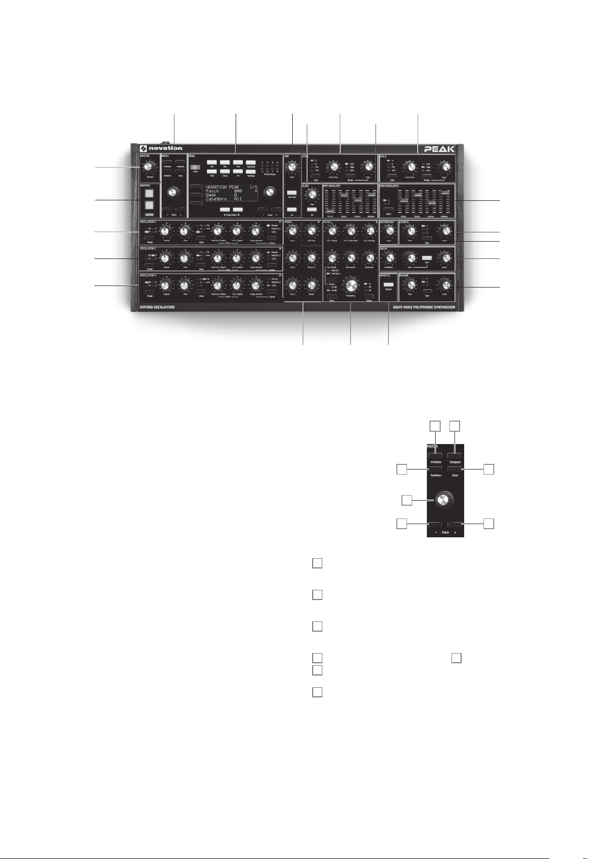
Top Pan el
Peak’s control surface is divided logically into functional areas, with signal generation and
treatment broadly following a left-to-right sequence.
PATCH LFO 1
MASTER
ANIMATE
OSCILLATOR 1
OSCILLATOR 2
OSCILLATOR 3
• PATC H – load and save Patches
• OSCILLATOR 1 – Primary sound generator
• OSCILLATOR 2 – Primary sound generator
• OSCILLATOR 3 – Primary sound generator
• LFO 1 – low frequency oscillator, modulates filter and oscillator Shape
• LFO 2 – low frequency oscillator, modulates the pitch of Oscs 1, 2 & 3
• MIXER – sums oscillator waveforms, ring modulator output and noise
• AMP ENVE LOPE – controls how signal amplitude varies with time
• MOD ENVELOPES – controls how other synth parameters vary over time
• GLIDE – enables a glide between successive notes
• ARP – arpeggiator function generates note patterns
• FILTER – modifies frequency content of signal
• EFFECTS – adds distortion, echo, reverb and chorus effects to overall sound
• MENU – 4 x 20 character display for Patch selection and extended parameter
control
• ANIMATE – momentary buttons for instant sound modification
ARPMENU LFO 2
GLIDE
AMP
ENVELOPE
MIXERFILTEREFFECTS
Controls, section by section
PATC H:
3
5
MOD ENVELOPES
CHORUS
DISTORTION
DELAY
REVERB
1
2
4
66
Initialise – pre ss this button to reset all synth param eters to the default values of the
1
Initial Patch – se e “Init Patch – parameter table” on page 37 for a list. This prov ides a
rapid way getting back to a bare “star ting point” for fresh sound creation.
Compare – press (and hold) this button to hear an “unmodified” version of the
2
currently loaded Patch. This allows you to com pare the origina l version with the effects of
any tweaking that you’ve done since loading it.
Audition – press to hear the current synth sound even without a keyboard (or other
3
controller) connected. The note played will always be middle C ( C3) . This corresponds to
MIDI note number 60.
Save – use in conjunction with Patch keys 6 to save modified Patches in me mory.
4
Patch select – use this rotary control to select a Patch, or a different memory loc ation
5
in which to save a modified Patch or new sound.
Patch +/- – these buttons provide an alternative method of scrolling through Patches.
6
5
Page 6
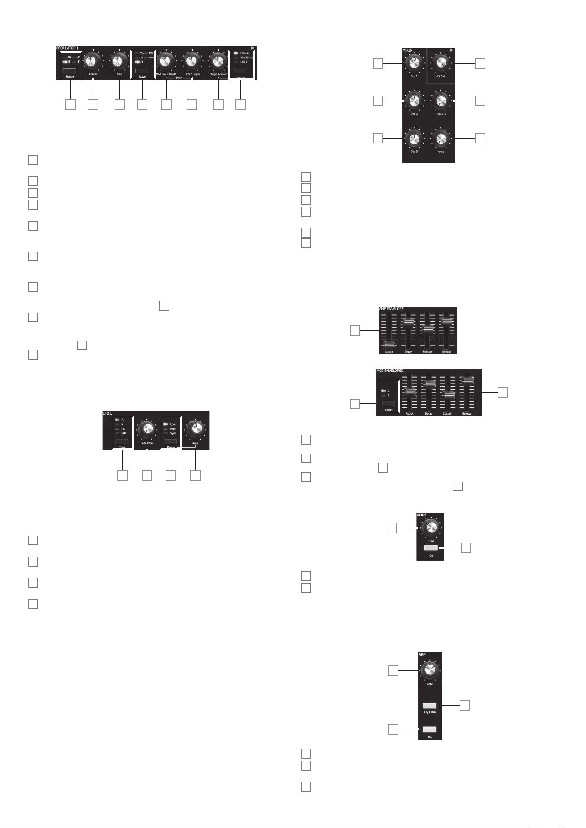
OSCILLATORS:
MIXER:
7 8 9 10 11 12 14 13
The three Oscillators have identical sets of controls. All have further parameters available
for adjustment via the menu system; these are described in det ail later in the User Guide.
Range – steps through the oscillator’s base pitch ranges. For standard concert pitch
7
(A3 = 440 Hz), set to 8’.
Coarse – adjusts the pitch of the selected oscillator over a range of ±1 octave.
8
Fine – adjusts the oscillator pitch over a range of ±100 cents (±1 semitone) .
9
Wave – steps through th e range of available oscillator waveforms – sine, triangular,
10
sawtooth, pulse and more (the menu offers various additional waveforms for more).
Mod Env 2 D epth – controls the degree by which the oscillator pitch changes a s a
11
result of modulation by Envelope 2. A ll Modulation Depth controls are “centre-zero” and
thus both pitch increases and decreases can be obtained.
LFO 2 Dep th – controls the degree by which the oscillator p itch changes as a result of
12
modulation by LF O 2. Pitch c hanges are bi-polar (up and down ); uni-p olar pitch modulation
is available by the use of the Modulation Matri x.
Source – this button se lects a source for further variati on of the waveform sha pe. The
13
options are: mo dulation by Envelope 1 (Mod Env 1), modulation by LFO 1 ( LFO 1) or
manual control by the Shape Amount control 14.
Shape Amount – controls fur ther modifications of the waveform shape, and is active
14
for all wave shapes. With pulse waves, it adjusts the pulse width; with sine, triangle and
sawtooth waves, it makes subtle changes to the wave shape . When more is selected by
the Wave switch 10, the control selects dif ferent areas of th e wavetable. When S ource
is set to Mod Env 1 or LFO 1, it acts as a Modulation Depth control. N ote that the
13
wave shape may be modulated by more than one source simultaneously, by differing
amounts.
19
20
21
Osc 1 – controls level of Oscillator 1’s waveform.
19
Osc 2 – controls level of Oscillator 2’s waveform
20
Osc 3 – controls level of Oscillator 3’s waveform
21
Ring 1* 2 – controls the Ring Modulator output level: the inputs to the Ring M odulator
22
are Osc 1 and Osc 2.
Noise – controls how much white noise is added.
23
VCA Gain – this effectively controls the mixer output level : it adjusts the signal level
24
between the Amp Envelope and Effects sections. See page 17.
AMP ENVELOPE, MOD ENVELOPES:
All three envelopes have further parameters available for adjustment via the menu syste m;
these are described in detail later in the User Guide.
24
22
23
25
LFO 1 & LFO 2 :
15 16 17 18
The two LFOs have identical sets of controls . Both have further parameters available for
adjustment via the menu system; these are de scribed in detail later in the User Guide. The
outputs of either LFO may be used to modulate numerous other synth pa rameters.
Type – steps through the available wavefor ms: triangle, sawtooth, square, sample and
15
hold. T he associated LEDs give a visual indication of the LFO s peed and waveform.
Fade Time – sets the timing of the LFO’s action: it is possible to “ramp” th e LFO up or
16
down or to delay its ef fect. T he options are set in the LFO me nu.
Range – selects High or Low; the third option is Sync, which synchronises the LFO
17
frequency to the internal a rp clock or to an exte rnal MIDI clock if one is present..
Rate – sets LFO frequency.
18
26
27
Amp Enve lope controls – a set of four 30 mm s liders adjusting the standard ADSR
25
parameters (Attack , Decay, Sustain and Release) of the amplitude envelope.
Mod Envelope controls – an i dentic al set of sliders, adjusting the parameter s of the two
26
modulation envelopes (see 27 below).
Select – Peak generates two ind ependent Mod Envelopes ; this button selects which
27
of these (Mod 1 or Mod 2) the Mod Envelope sli ders 26 control.
GLIDE:
28
29
Time – sets the portamento glide time.
28
On – enables/disables the Glide function.
29
ARP:
The Arpeggiator has fur ther parameters available for adjustment via the menu system ;
these include basic set tings such as BPM, pattern selection and octave range. The se are
descr ibed in detail later in the User Guide.
32
31
30
On – turns the Arpeggiator on and off.
30
Key Latc h – when the A rpeggiator is running, pressing Key Latch simulates the effect
31
of holding the keys down continuously, until the keys are released.
Gate – sets the basic duration of the notes played by the A rpeggiator.
32
6
Page 7
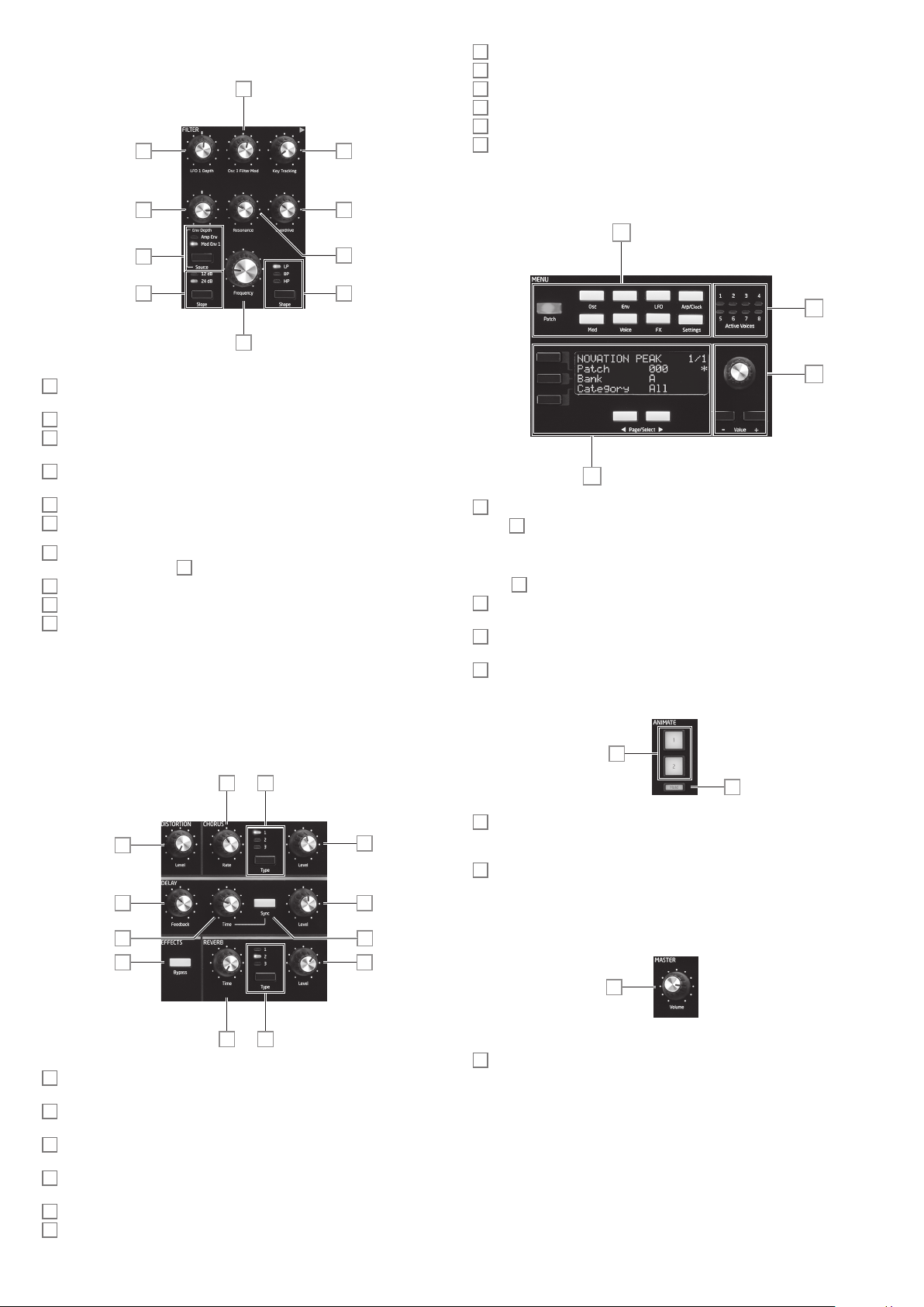
FI LTE R:
40
39
38
41
42
37
36
REVERB: Type – emulates spaces of three different sizes: 3 is the largest.
49
REVERB: Level – controls the “amount” of reverberation.
50
CHORUS: Rate – adjusts the rate of chorus modulation.
51
CHORUS: Type – lets you select one of three different chorus algorithms.
52
CHORUS: Level – controls the degree of chorus effect.
53
EFFECTS: Bypass – the three time-doma in effects may be sw itched in or out with
54
this button.
MENU:
56
34
33
35
Shape – steps through the three types of filter: low-pass ( LP), band-pass (BP) or
33
high-pass (HP).
Slope – sets the slope of filter to either 12dB or 24dB per octave.
34
Frequency – large rotary knob controlling the filter’s cut-off frequency (LP or H P), or
35
its centre frequency (BP).
Resonance – adds resonance (an increased response at the filter frequency) to the
36
filter characteristic.
Overdrive – adds a degree of pre-filter distortion to the mixer output.
37
Source – selects whether the filter is to be varied by Mod Envelope 1 (Mo d Env 1) or
38
the Amp Envelope (Amp Env).
Env dept h – controls the degree by which the filter frequency is modified by the
39
envelope selected by Source 38.
LFO 1 depth – contro ls the degree by which the filter frequency is modified by LFO 1.
40
Osc 3 Filt er Mod – allows the filter frequency to be modulated directly by Oscillator 3.
41
Key Tracking – controls the degree by which the keyboard position of the note being
42
played varies the filter frequency b etween 0 and 100%
EFFECTS:
Peak’s Effects section comprises three different DSP-based processors producing timedomain effects, plus an analogue distortion generator.
The Delay, Reverb and Chorus effects have fur ther parameter s available for adjustment via
the menu system; these are described in detail later in the User G uide.
58
57
55
20 character x 4 row OLED disp lay. Displays one of the nine menus selected by the
55
buttons 56. Pages within each menu may be selected with the two Page/ Select buttons
below the display. Adjusti ng any of Peak’s rotary controls (except MASTER and PATC H)
invokes a n alternative display showing the value of the parameter being adjusted until
the control is released . The three buttons to the lef t of the display assign the parameter
controls 57 to a particular row of the pag e being displayed.
Nine buttons selecting the menu to be displayed: Patch, Osc , Env, LFO, Arp/Clock,
56
Mod, Voice, FX and Settings.
Param eter adjustment may either be made rapidly by th e rotary control or incremented /
57
decremented one parameter value at a time with the Valu e + / Value - buttons.
Active Voice – eight LEDs, indicating which of the eight voices are currently active.
58
AN IMAT E:
59
51 52
43
46
53
47
4544
54
50
48 49
DISTORTION: Level – controls the amount of analogue distortion applied to the sum
43
of all eight voice s.
DE LAY: T im e – sets the timing of the delayed signal (echo) added to the original.
44
Maximum delay is approx. 1.4 seconds.
DE LAY: S yn c – selecting Sync allows the delay time to be synchronised to the internal
45
clock or an incoming MIDI clock.
DELAY: Feedback – allows the delayed signal to be fed back to the input of th e delay
46
processor, creating multiple echoes.
DE LAY: L ev el – controls the volume of the del ayed signal.
47
REVERB: Time – adjusts reverberation decay time. (The maximum time is longer than
48
you’ll ever be likely to need! )
60
AN IMAT E 1 and 2 – add an “instant” effect to the sound currently being generated.
59
These buttons are great in live per formance: the nature of the extra effect will be
determined by the Patch in use.
Hold – press ing Hold will “lock” th e Animate function in an “On” state. You can either
60
press Hold before pressing ANIM ATE , or vice-versa. Pressing A NIM ATE a second time
relea ses both the Animate and Hold functions.
MASTER:
61
Volume – master volume control for the synth’s audio output; this also controls the
61
headphones output level.
7
Page 8
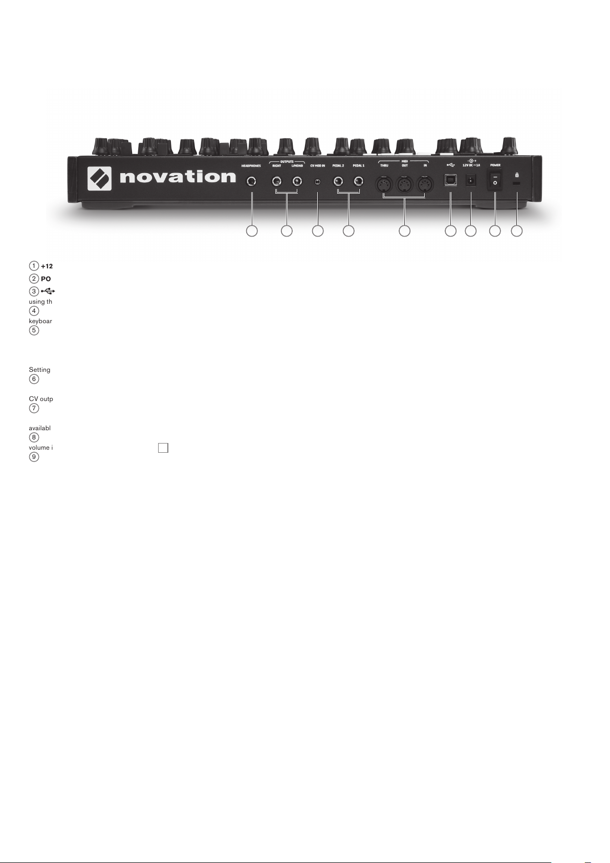
Rear Panel
8
1
+12V DC – connect the supplied PSU here.
2
POWER – on /off switch.
3
– standard USB 2.0 or 3.0 por t. Connect to a Type A USB port on a c omputer
using the supplied cable. Note that the USB port only carries MIDI data, not audio.
4
MIDI IN, OUT and THRU – standard 5-pin DIN MIDI sockets for connecting Peak to a
keyboard or other MIDI-equipped hardware.
5
PEDAL 1 and PEDA L 2 – two 3-pole (TRS) ¼” jack sockets for connection of
switch (e.g., sustain) and/or expression pedals. The sockets detect switch pedal polarity
automatically. Expression pedals are also detected automatica lly and can be routed directly
as sources available to the Modulation Matrix. Switch pedal functi ons are configured in the
Settings menu.
6
CV MOD I N – 3.5 mm jack socket for connecting an external Control Voltage source in
the range of +/-5 V. This permits other a nalogue instruments (equipped with a compatible
CV output) to modulate Peak’s sounds.
7
OUTPUTS – two ¼” 3-pole (TRS) jack sockets carrying Peak’s output signal. Use
both L/MONO and RIGHT for full stereo: if RIGHT is unconnected, a mono (L+ R) sum is
available at L/MONO. Outputs are pseudo-balanced.
8
HEADPHONES – 3-pole (TRS) ¼” jack socket for stereo headphone s. Phones
volume i s adjusted by the VOLU ME control 61.
9
Kensington Security Slot – to secure your synth.
7
6
5
4
3
1 2 9
8
Page 9
G E T TIN G S TAR T E D
Peak may, of course, be used simply as a standalone synthesiser with a mas ter keyboard
connected to its MIDI IN socket. However, there are m any more possibilities , and how you
choose to integrate it into your existing synth /recording setup will be determined by the
other equipment you have and your own imagination!
Below are three examples illustrating how Peak could form part of a synth setup. We’ve
used Novation or Focusrite products throughout (we would, wouldn’t we? ), but of course
you can use whatever equipment you have in your system provided it’s functionally
equivalent, of course. Note: for clarit y, we’ve omit ted audio signal paths from the diagrams.
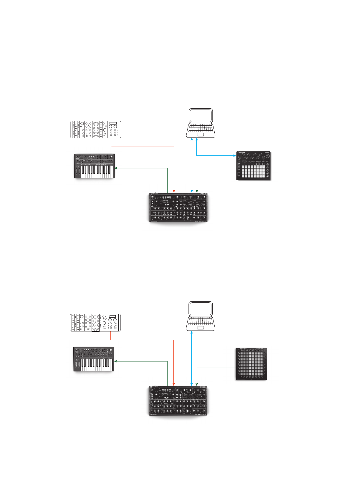
Example 1
Euroack
Computer
LFO OUT
MIDI IN
Novation Bass
Station II
Here you could use a pad controller such as the Novation Circuit to trigger sounds both
in Peak and another synth such as a Novation Bass Station II. An ex ternal modular LFO
in a Eurorack could be used to modulate one or more parameters in Peak via the CV
connection. A ll MID I data gets recorded in the DAW via USB connections.
Euroack
MIDI THRU
CV IN
Novation
Peak
Example 2
USB
MIDI IN
USBUSB
Computer
MIDI OUT
Novation
Circuit
LFO OUT
MIDI IN
Novation Bass
Station II
In the second example, a Launchpad Pro in stand-al one mode r eplaces the Circuit. This
would permit Peak to be played directly from the Launch pad Pro, t aking advantage of its
polyphonic aftertouch capability.
MIDI THRU
CV IN
Novation
Peak
USBUSB
MIDI IN
MIDI OUT
Novation
LaunchPad Pro
9
Page 10
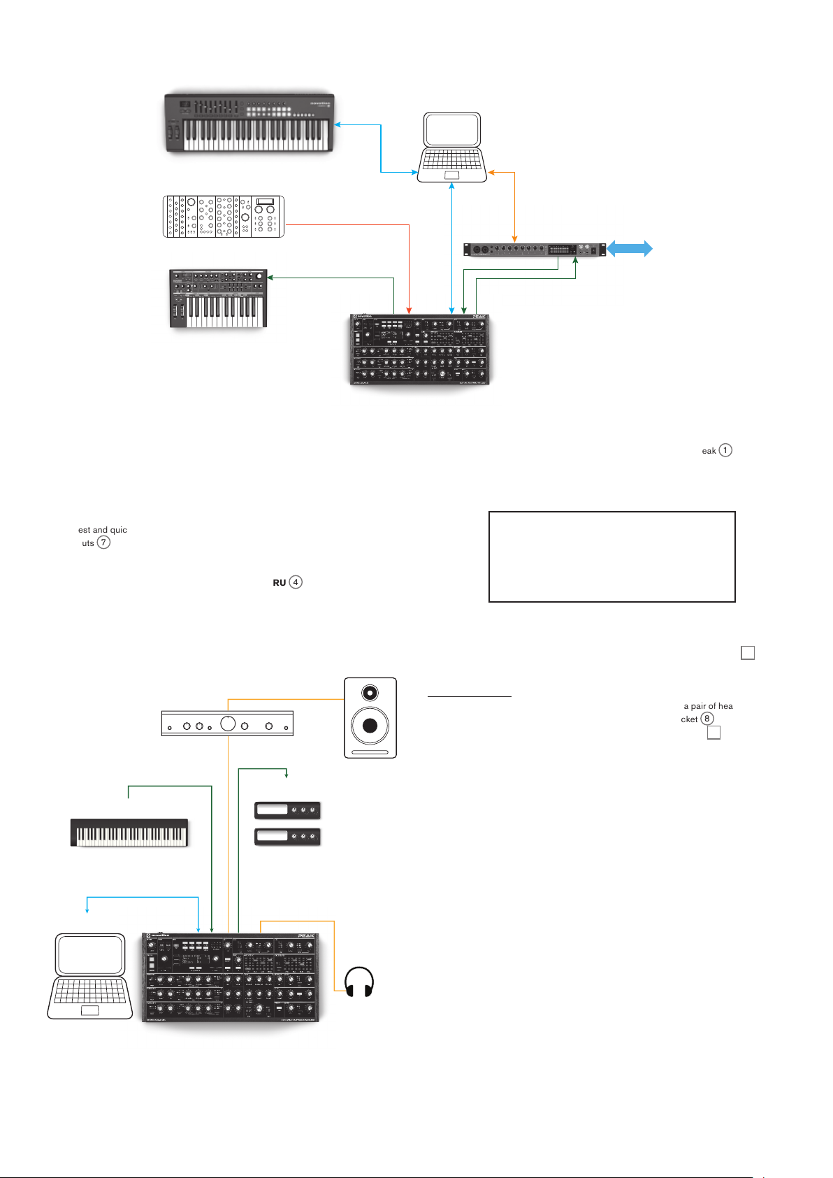
Euroack
Example 3
Computer
USB
Novation
Launchkey
LFO OUT
USB
Eurorack
MIDI IN
Novation Bass
Station II
In this example, a Focusrite Clarett audio interface is used to enable “real-world”
instruments to be record ed in the DAW as well as synth sounds . A keyboard controller is
used to tr igger both Peak and a second synth, such as a Bass Station II, with the Clarett
conver ting MIDI data sent from the computer via a Thunderb olt link to c onventional MI DI
data.
The sim plest and quickest way of finding out what Peak can do is to connect the re ar
panel outputs
powered speaker or other means of monitoring the output.
If using Peak with other sound modules, connect MI DI THR U
module’s MIDI IN, and daisy-chain fur ther modules in the usual way. If using Peak with
a master keyboard, connect the master keyboard’s MIDI OUT to MIDI IN on Peak , and
ensure that the master keyboard is set to transmit on MIDI channel 1 (the synth’s default
channel).
7
– in either mono or stereo - to the input of a power ampli fier, audio mixer,
4
to the nex t sound
Audio Out Mono
THUNDERBOLT
Focusrite ClarettFocusrite Clarett
AUDIO I/O
MIDI THRU
CV IN
USBUSB
MIDI IN
MIDI OUT
MIDI OUT
MIDI IN
Novation
Peak
With the amplifi er or mixer off or muted, connect the AC adaptor to Peak
into the AC mains. Turn the synth on : after completing its boot sequence, Peak will load
Patch 000, and the LCD display will confirm thi s:
Utopian Streams 1/1
Patch 000 H
Bank A
Category All
“Utopian Streams” is the name of the factory Patch in Bank A, memory location 000.
Turn on the mixer/amplifie r/powered speakers, a nd turn up the Volume control 61 until you
have a healthy sound level from the speaker when you play.
Using headphones
Instead of a speaker and /or an audio mixer, you may wish to use a pair of headphones.
These may be plugged into the rear panel headphone output socket
are still active when headphones are plugged in. The Volume control 61 also adjusts
headphone level.
8
. The main outputs
1
, and plug it
10
USB
MIDI IN
Master Keyboard
MIDI OUT
Sound Modules
NOTE: Peak’s headphone amplifier is capable of outputting a high signal level; please take
care when setting the volume.
Headphones
Page 11
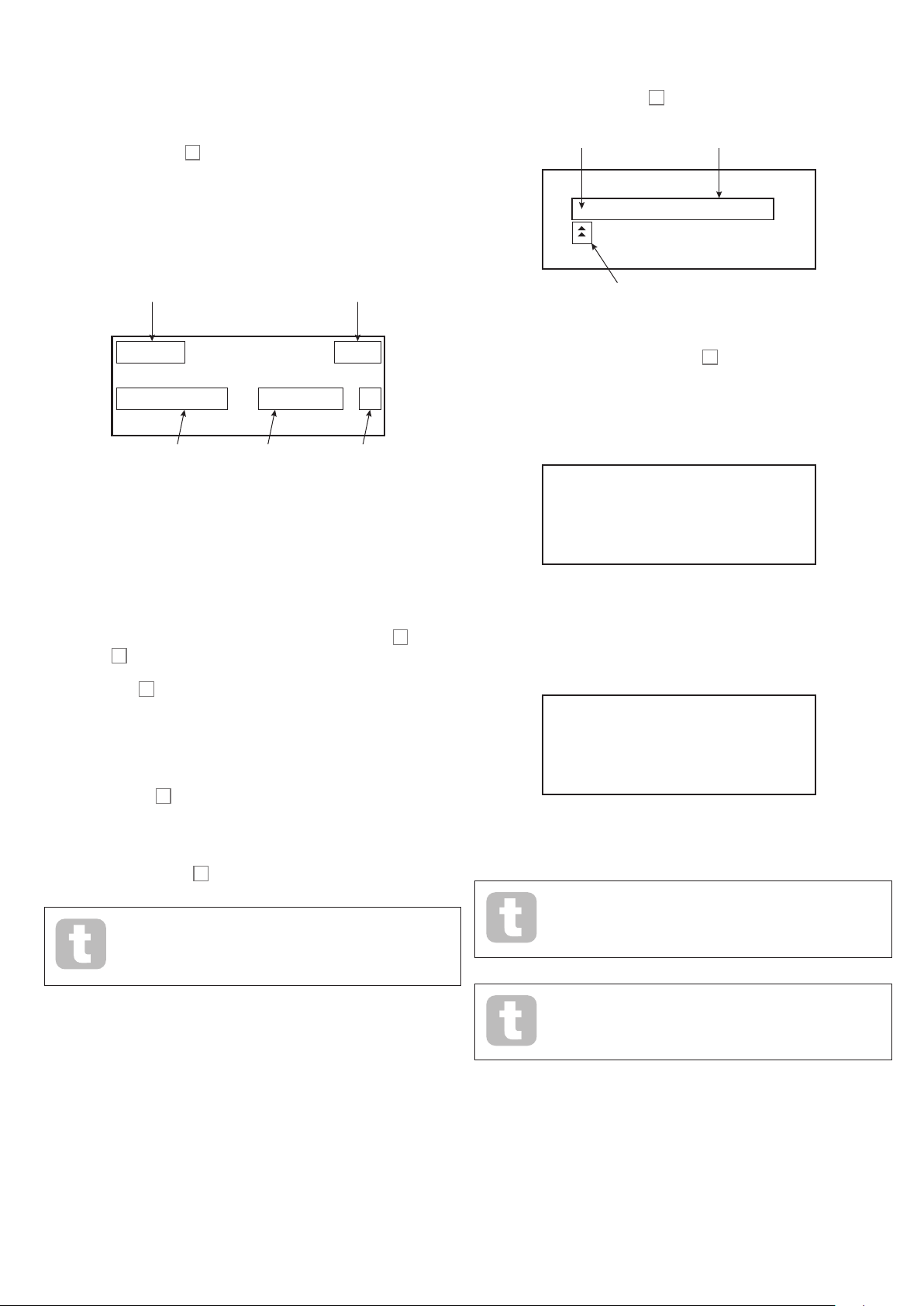
Menu Navigation
LFO 2 4/6
SAVE RENAME 1/3
SAVE LOCATION 2/3
Utopian Streams
Although most of the key parameters affecting the nature of the sound Peak generates are
immediately accessible through dedicated, “per-function” rotary controls and switches,
many further parameters and synth settings can be modifie d using the OLED display and
its associated controls.
Peak’s menu system has been designed to be as simple and consistent as possible. T he
eight buttons above the display 56, plus Patch, select one of nine menus. Each menu ha s
multiple pages: use the Page/Select buttons to scroll through the pages in sequence.
On each p age, Row 1 is a “title” row and stays fixed. Rows 2, 3 and 4 each displ ay a
parameter for modification; some pages do not have all data in all rows. Use the three
buttons to the lef t of the dis play to select the row to edit: the active row is indic ated by an
asterisk. The parameter value m ay be adjusted either by the rotary control or the
Value +/- buttons.
Saving Patches
Patches can be saved to any of the 512 memor y locations, but remember that if you save
your set tings to any location in Banks A or B, you will overw rite one of the factory presets.
To save a Patch press the Save button 4. The OLED display changes as shown below:
Character to
be inserted
Initial Patch
Name
I Utopian Streams H
H
-space->
Synth section
Page 4 of 6
Phase Free
MonoTrig Legato H
Slew 0
Parameter to
be adjusted
Loading Patches
Peak ca n store 512 Patches in memory, arranged in four Banks of 128; the Banks are
designated A to D. Banks A and B are pre-loaded with 256 great factory Patches
especially created for Peak, while Banks C and D are for storing your own Patc hes and
come pre-loaded with th e same default “initial” Pa tc h Init Patch. See page 37
for the default synth parameters this Patch contains . This initial Patch will always be the
star ting point for creating new sounds “from scratch”.
A Patch is loaded by simply selecting its number with the rotary patch selector 5 or the
Patch buttons 6. It is immediately active.
The Compare button 2 is a really useful feature a s it lets you h ear the Patch you loaded
in its “factory” state, ignoring any changes or twe aks you’ve been mak ing. Hold the button
down to hear the original Patch: when you release it, you’ll be back to your modified
version. This i s a useful feature to use when you’re about to save a new Patch into a
memor y location that might already contain a Patch you want to retain – you ca n press
Compare during the Save process to check what’s in the intended memory location.
Current
parameter
value
Row 3 is
selected
Cursor
You can now give the Patch you want to save a name. The existing name is displayed
initially; use the Row 2 but ton ( H) to move the cursor to the character position to be
changed and then use the rotary parameter control 57 to select the new letter. Repeat
this process one character at a time. Upper c ase, lower case, numbers, punctuation marks
and space characters are all available in sequence from the rotary control. Use the Row
4 button to insert a space instead of a character. When you have entered the new name,
press Page/Select H to select Page 2, where you de cide which memory location the
modifi ed Patch will be saved in.
Patch 000 H
Bank A
Now you can enter the memory location by Bank and number. Note that the name of the
Patch currently in the memory location you select is displaye d on Row 4, to re mind you
what it is in case it’s something you don’t want to overwrite. Press Page/ Selec t H again to
select Page 3, and you can (if you wish) assign your Patch to one of several pre-determined
categories.
SAVE CATEGORY 3/3
Category None h
You can pres s Initialise 1 at any time to load a copy of the default initial Patch. Doing
so does not overwrite the previous Patch, though you will lose any modifications that you
made to it i f you haven’t saved it in a user Patch location.
If you’re working without a keyboard, you can generate a note (corresponding to middle C)
at any time by pressing Audition 3.
Note that when you ch ange Patc h, you lose the current synth settings. If
the current settings were a modified version of a store d Patch, these
modifi cations will be lost. Thus it is always advisable to save your settings
before loading a new Patch. See Saving Patches.
When you have done this, press Save again, and the display will confirm that the Patch is
saved.
You may save a modified Patch to the same location, if you are happy for
the earlier version to be overwritten. This can easily be achieved by
pressing Save four times in succession.
Peak Factory Patches can be downloaded from the Novation website if
they have been accidentally overwritten. See page 36.
11
Page 12

Basic Operation – sound modification
01Fine
Once you have loaded a Patch you like the sound of, you can modify the sound in many
different ways using the synth controls. Each area of the control panel is dealt with in
greater depth later in the manual, but a few funda mental points should be noted first.
The OLE D display
The OLED display will show the last menu page selected until a rotary control or slider is
moved on the control panel, when it changes to confirm the control being moved, together
with the instantaneous parameter value and the parameter va lue for the currently loade d
Patch:
current -17
saved val +0
Many rotary controls have a parameter range of 0 to +127. Others are effectively “centreoff”, and have a parameter ra nge of either -64 to + 63 or -128 to +127.
The display reverts to the previous menu page a short time (user-definable) af ter the co ntrol
is rele ased. I f no control is touch ed for 10 minutes, the display tur ns off, but will resume
immediately a control or menu button is selected.
The one exception to this is the Master volume rotary control.
Parameter adjustment
As with traditional analogue synths, most of the primary sound modification controls on
Peak are dedicated, physical rot ary controls or switches, providing instant access to the
most commonly needed sound parameters.
MIDI control
Peak has a very high degree of MIDI implementation, and almost ever y control and synth
parameter is able to trans mit MIDI data to ex ternal equipment, and similar ly, the synth may
be controlled in almost every respect by incoming M IDI data from a DAW, sequencer or
master control keyboard.
The Settings menu has numerous options for enabling various aspects of MIDI control,
which include M IDI Channel setting, Arpeggio MID I Out, Af tertou ch, CC /NR PN transmit/
receive and Program/Bank Change transmit/receive. Please see page 33 for full details.
The factory default is for all MID I transmit/receive options to b e On, and M IDI Channel 1 is
set as the active ch annel.
The Animate Buttons
Each of the two ANIMATE but tons 59 may be programmed to provide an instant
modifi cation to the synth’s sound, which persists for as long as th e button is pressed. This
is a great way of adding sound ef fects “on the fly” in live performance.
The ANIM ATE buttons are programmed using the Modulation Matrix, and appear in the
list of Sources on Page 2 of the Mod menu. Each button may be assigned as a modulating
source for any of the Destinations available in the Mod M atrix. See page 26 for full
details.
Many more parameters are available for adjustment in most of the synth sections via the
menu system; these tend to be parameters that you wouldn’t need imm ediate ac cess to
during a live per formance. Those in the Osc, E nv, LFO, Arp/Clock, Voice and FX menus
all affect the relevant sections of sound generation and treatment directly, while the Mod
menu lets you interconnect different synth sections with the Modulation Matrix.
The Filter knob
Adjusting the frequency of the synth’s filter is probably the most commonly-used method of
sound modification. For this reason, Filter Frequency has a large rotary c ontrol 35 near
the bottom of the pa nel. Experiment with different types of patch to hear how cha nging the
filter frequency alters the characteristic of dif ferent t ypes of sound. Also listen to the effect
of the three different filter Shapes.
Pitch and Mod wheels
Any MIDI keyboard controller used with Pe ak will be fitted with a standard pair of
synthesiser control wheels, Pitch and Mod (Modulation). Pitch is usually spring-loaded
and will return to its centre position. The range of control of Pitch is adjustable ( with the
BendRange parameter - see page 18) in semitone increments up to +/-2 oct aves; the
default setting is +/-1 octave.
The Mod wheel’s precise function varies with the patch loaded; it is used in ge neral to add
expression or various elements to a synthesized sound. A common use is to add vibrato to
a sound.
It is possible to a ssign the Mod wheel to alter various parameters making up the sound
– or a combination of parameters simultaneously. This topic is discussed in more detail
elsewhere in the manual. See “The Modulation Matrix” on page 26.
The Arpeggiator
Peak includes an arpeggiator (the ‘ARP’), which allows arpeggios of va rying complexity
and rhy thm to be played and ma nipulated in real-time. The Arpeggiator is enabled by
pressing the Arp ON button 30.
If a single key is pre ssed, the note will be retriggered by the arpeggiator, at a rate
determined by the ClockRate parameter on Page 1 of the Arp menu. If you play a
chord, the arpeggiator identifies its notes and plays them individually in sequence at the
same rate (this is termed an arpeggio pattern or ‘arp sequence’); thus if you play a C major
triad, the selected notes will be C, E and G.
Adjusting Gate 32, and the Ty p e, Rhythm and Octaves parameters on Page 2 of
the Arp menu w ill alter the rhythm of the pat tern, the way the sequence is played and the
note range in a variety of ways . See “The Arpeggiator” on page 29 for full details.
12
Page 13

SYNTHESIS TUTORIAL
Time Time
A B
Oscillators Mixer Filter Amplifier
Square Wave
Volume
Harmonic
1 2 3 4 5
Volume
Harmonic
1 3 5 7
Triangle Wave
This section covers the general principles of electronic sound generation and processing
in more detail, including references to Peak’s facilities where relevant. It is recommended
that this chapter is read carefully if analogue sound synthes is is an unfamilia r subjec t.
Users familia r with this subject can skip this section and move on to the next.
To gain an understanding of how a synthes iser generates sound it is helpful to have an
appreciation of the components that make up a sound, both music al and non-musical.
The only way that a sound may be detected is by a ir vibrating the eardrum i n a regula r,
perio dic manner. The brain interprets these vibrations (very accurately ) into one of a n
infinite number of different types of sound.
Remar kably, any sound may be described in ter ms of just three properti es, and all sounds
always have them. They are:
• Pitch
• Tone
• Volume
What makes one sound different from anothe r is the relative mag nitudes of the three
properties a s initially present in the sound, and how the properties change over the
duration of the sound.
With a musical synthesiser, we deliberatel y set out to have precise control over these three
properties a nd, in particular, how they can be changed during the “li fetime” of the sound.
The properti es are of ten given different names: Volume may be refer red to as Amplitude,
Loudness or Level, Pitch as Frequency and Tone as Timbre.
Pitch
As state d, sound is perceived by air vibrating the eardrum. The pitch of the sound is
determined by how fast the vibratio ns are. For an adult human, the slowest vibration
perceived as sound is about twent y times a second, w hich the brain interprets as a bass
sound ; the fastest is many thousands of times a second, which the brain interprets as a
high treble sound.
Having shown that just three elements may defi ne any sound, these elements now have to
be realised in a musical synthesiser. It is logical that different sections of the synthesiser
‘synthesize’ (or create) each of these different elements.
One section of the synthesiser, the Oscillators, provide raw waveform signals which
define the pitch of the sound along with its raw harmonic content (tone). These signals
are then mixed together in a section called the Mixer, and the resulting mixture is then fed
into a section called the Filter. This makes further alterations to the tone of the sound, by
removing (filtering ) or enhan cing certain of the harmonics. Lastly, the filtered signal is fed
into the Amplifier, which determines the final volume of the sound.
Additional synthesiser sections - LFOs and Envelopes - provide further ways of altering
the pitc h, tone and volume of a sound by interacting with the Oscillators, Filter and
Amplifier, providing changes in the char acter of the sound which can evolve over
time. Because LFOs’ and Envelopes’ only purpose is to c ontrol ( modulate) the other
synthesiser sections, they are commonly known as ‘modulators’.
These various synthesiser sections will now be covered in more detail.
The Oscillators And Mixer
The Osc illator section is really the hear tbeat of the synthesiser. It g enerates an electronic
wave (which creates the vibrations when eventually fed to a loudspeaker). This waveform
is produced at a controllable musical pitch, initially determined by the note played on the
keyboard or contained in a received MIDI note message. The distinctive tone or timbre of
the waveform is actually determined by the waveform’s shape.
Many years ago, pioneers of music al synthesis discovered that just a few distinctive
waveforms contained many of the most useful harmonics for mak ing musi cal sounds. The
names of these waves reflec t their actual shape when viewed on an instrument called an
oscilloscope, and they are: Sine waves, Square waves, Sawtooth waves , Triangle waves
and Noise. Each of Peak’s Oscillator sections can generate all these waveforms, and can
generate non-traditional synth waveforms as well. ( Note that Noise is actually generated
independently and mixed in with the other waveforms in the Mixer s ection .)
If the number of pe aks in the t wo wavefor ms (vibrations) are counted, it will be seen that
there are exactly twice as many peaks in Wave B as in Wave A. (Wave B is actually an
octave higher in pitch than Wave A.) It is the number of vibrations in a given period that
determines the p itch of a sound. This is the reason that pitch is sometimes referred to as
frequency. It is the number of waveform peaks counted during a given period of time which
defines the pitch, or frequency.
Tone
Musical sounds consist of several different, related pitches occurring simultaneously. The
lowest is referred to as the ‘ fundamental’ pitch and corresponds to the perceived note of
the sound. Other pitches making up the sound which ar e related to the fundamental in
simple mathematical ratios are called harmonics. The relative loudness of each harmonic
as compared to the loudness of the fundamental determines the overall tone or ‘timbre’ of
the sound.
Consider two instruments such as a harpsichord and a piano playing the same note on the
keyboard and at equal volume. Despite having the same volume and pitch, the instruments
still sound distinctly different. This is because the different note-ma king mechanisms of
the two instruments generate dif ferent sets of harmonics; the harmonics present in a piano
sound are different to those found in a harpsi chord sound.
Volume
Volume, w hich is of ten referred to as the amplitude or loudness of the sound, is determined
by how large the vibrations are. Very s imply, listening to a piano fro m a metre away would
sound louder than if it were fifty metres away.
A B
Each waveform (except Noise) ha s a specific set of musically-related harmonics which can
be manipulated by further sections of the synthesiser.
The diagrams below show how these waveforms look on an oscilloscope, and illustrate
the relative levels of their harmonics. Remember, it is the relative levels of the various
harmo nics present in a waveform which deter mine the tonal character of the final sound.
Sine Waves
Volume
1
Sine Wave
Harmonic
These possess just one harmoni c. A sine waveform produces the “purest” sound because
it only has this single pitch (frequency).
Triangle Waves
Volume
1 3 5 7
Triangle Wave
Harmonic
These contain only odd harmonics. The volume of each decre ases as the square of its
position in the harmonic series. For example, the 5th harmonic has a volume 1/25th of the
volume of the fundamental.
Volume
13
Page 14

Sawtooth Waves
Volume
Harmonic
1
Sine Wave
Square Wave
Volume
Harmonic
1 2 3 4 5
Volume
Harmonic
1 3 5 7
Triangle Wave
Volume
Harmonic
1 3 5 7
Triangle Wave
Volume
Harmonic
1
Sine Wave
Sawtooth Wave
Volume
Harmonic
Square Wave
Volume
Harmonic
1 2 3 4 5
Volume
Harmonic
1 3 5 7
Triangle Wave
1 2 3 4 5
OSC 1
OSC 2
X
OSC 1
OSC 1 VOLUM E
OSC 2 VOLUM E
OSC 3 VOLUM E
COMPLEX
WAVEFORM
MIX OF
OSC1, 2, 3,
NOISE AND
RING
MODULATOR
MIXER
INPUT TO
FILTER
OSC 2
OSC 3
NOISE
RING MOD
NOISE
RING MOD
harmo nic content present in each of the two oscillator signals, and will consist of a series
of sum and difference frequencies as well as the frequencies present in the original signals.
Volume
Sawtooth Wave
1 2 3 4 5
Harmonic
These are rich in harmonics, and contain both even and odd harmonics of the fundamenta l
frequency. The volume of each is inversely proportional to its position in the harmonic
series.
Square / Pulse Waves
Volume
Square Wave
1 2 3 4 5
Harmonic
These contain only odd harmonics, which are at the s ame volume as the odd harmonics in a
sawtooth wave.
It will b e noticed that the square waveform spends an equal amount of time in its ‘high’
state as in its ‘low’ state. This ratio is known as the ‘duty cycle’. A square wave always has
a duty cycle of 50 % which means it is ‘high’ for half the cycle and ‘low’ for the other half.
Peak lets you adjust the duty cycle of the basic square waveform (vi a the Shape Amount
control) to produce a waveform which is more ‘rectangular’ in shape. These are often
known a s Pulse waveforms. As the waveform becomes more and more rectangular, more
even har monics are intro duced and the waveform changes its character, becoming more
‘nasal’ sounding.
The width of the pulse waveform (the ‘Pulse Wi dth’) can be altered dynamically by a
modulator, which results in the harm onic content of the waveform constantly changing. This
can give the waveform a very ‘ fat’ quality when the pulse width is altered at a moderate rate.
The Mixer
To extend the range of sounds that may be produced, typical analogue synthesisers have
more than one Oscillator ( Peak has three ). By using multiple Oscillators to create a sound,
it is pos sible to achieve ver y interesting harmonic mixes. I t is also possible to slightly
detune individual Oscillators against each other, which creates a ver y warm, ‘ fat’ sound.
Peak’s M ixer all ows you to cre ate a sound c onsisting of the waveforms of Oscillators 1, 2
and 3, a Noise source and the Ring Modulator output, all mixed together as required.
A pulse waveform sounds the same whether the duty cycle is – for example – 40% or 60% ,
since the waveform is just “inverted” and the harmonic content is exactly the same.
Noise
Noise is basically a random signal, and does not have a fundamental frequency (and
therefore has no pitch property). Noise contains all frequencies, and all are at the same
volume . Because it possesses no pitch, noise is of ten useful for creating sound effects and
percussion type sounds.
Ring Modulation
A Ring Modulator is a sound ge nerator that takes signals from two oscillators and
effectively “multiplies” them together. Peak’s Ring Modulator uses Oscillator 1 and
Oscillator 2 as inputs. The resulting output depends on the various frequencies and
14
Volume
50%
40%
10%
60%
1 2 3 4 5
The Filter
Peak is a
subtractive
music synthesiser.
Subtractive
implies that part of the sound is
subtracted somewhere in the synthesis process.
The Osc illator s provide the raw waveforms with plenty of harmonic content and the Filter
section subtracts some of the harmonics in a controlled manner.
There a re three b asic filter type s, all of which are available in Peak: low-pas s, band-pass
and high-pass. The type of filter most commonly used on synthesisers is low-pass. In a
low-pass filter, a “cut-off frequency” is chosen and any frequencies below this are passed,
while frequencies above are filtered out, or removed. The setting of the Filter Frequency
parameter dictates the point above which frequencies are re moved. This process of
removing harmonics from the waveforms has the effect of changing the sound’s character
or timbre. When the Frequency parameter is at maximum, the filter is completely “open” and
no frequencies are removed from the raw Oscillator waveforms.
In practice, there is a gradual (rather than a sudden) reduction in the volume of the
harmo nics above the cut-off point of a low-pa ss filter. How rapidly these harmonics reduce
in volum e as frequency increases above the cut-off point is determined by the filter’s Slope
parameter. The slope is measured in ‘volume units per o ctave’. Since volume is measured in
decibels, this slope is usually quoted as s o many decibels pe r octave
(dB /oct). The higher the number, the greater the rejection of harm onics above the cut-off
point, and the more pronounced the filtering effect. Peak’s filter section prov ides two
slope s, 12 dB/oct and 24 dB/oct.
A further important parameter of the filter is Resonance. Frequencies at the cut-off point
may be increased in volume by advancing the filter’s Resonance control. This is useful for
emphasising certain harmonics of the sound.
As Resonance is increased, a whistling-like quality will be introduced to the sound passing
through the filter. When set to very high levels, Resonance actually causes the filte r to
self-oscillate whenever a signal is being passed through it. The resulting whistling tone
Page 15

being produce d is actually a pure sine wave, the pitch of which depends on the setting of
Cut-off
Volume
Frequency
Frequency
Cut-off
Frequency
Volume
Volume
Frequency
Cut-off
Frequency
Volume
Frequency
Cut-off
Frequency
Frequency
Cut-off
Frequency
Frequency
Volume
Volume
Frequency
Cut-off
Frequency
Frequency
Cut-off
Frequency
TIME
KEY "ON" KEY "OFF"
TIME
KEY "ON" KEY "OFF"
VOLUME
TIME
KEY "ON" KEY "OFF"
TIME
KEY "ON" KEY "OFF"
VOLUME
TIME
KEY "ON" KEY "OFF"
VOLUME
TIME
the Frequency control (the filter’s cut-off point). This resonance-produce d sine wave can
actually be used for some sounds as an additional sound source if wished.
The diagram below shows the response of a typical low-pass filter. Frequ encies above the
cut-off point are reduced in volume.
Frequency
Volume
Frequency
When re sonance is added, the frequencies around the cut of f point are boosted in volume.
Cut-off
Frequency
Volume
Cut-off
Frequency
Volume
Frequency
Envelopes And Amplifier
In earlier paragraphs, the synthesis of the pitch and the timbre of a sound was described .
The nex t part of the Synthesis Tutorial describes how the volume of the sound is controlled.
The volume of a note created by a musical instrument often varies greatly ove r the duration
of the note, according to the t ype of instrument.
For example, a note played on an organ quickly attains full volum e when a key is pressed.
It stays at full volu me until the key is released, at which point the volume level falls instantly
to zero.
In addition to the traditional low- pass filter type , there are also high-pass and band -pass
types. On Peak, the filter type is selecte d with the Shape switch 33.
A high-pass filter is similar to a low-pass filter, but works in the “opposite sense”, so
that it is frequencies below the cut- off point which are remove d. Frequencies above the
cut-of f point are passed. When the Frequency parameter is set to minimum, the filter is
completely open and no frequencies are removed from the raw Oscillator waveforms.
Cut-off
Frequency
Volume
VOLUM E
A piano note quick ly attains full volume after a key is pressed, but gradually falls in volume
to zero af ter several seconds, even if the key is held.
VOLUME
A string section emulati on only at tains full volume gradually when a key is pressed. It
remains at full volume while the key is held down, but once the key is released, the volume
falls to zero fairly slowly.
KEY "ON" KEY "OFF"
VOLUME
With a band-pass filter, just a narrow band of frequencies centered around the cut-off point
is passed. Frequencies above an d below the band are removed. It is not possible to fully
open this type of filter and allow all frequencies to pass.
In an analogue synthesiser, changes to a sound’s character whic h occur over the duration
of a note are controlled by a section called an Envelope Generator. One (Amp Env) is
always related to th e Amplifier, which controls the note’s amplitude – i.e., the volume of
the sound – when the note is played. Each envelope generator has four main parameters,
which determine the shape of the envelope; these are often referred to as the ADSR
parameters.
15
Page 16

TIME
KEY "ON" KEY "OFF"
VOLUME
TIME
KEY "ON" KEY "OFF"
VOLUME
TIME
KEY "ON" KEY "OFF"
VOLUME
KEY "ON" KEY "OFF"
A waveshape often used for an LFO is a Triangle wave.
VOLUME
SUSTAIN
ATTAC K DECAY RELEASE
TIME
Attack Time
Adjusts the time it takes af ter a key is pressed for the volume to climb from zero to full
volume . It can be u sed to create a sound with a slow fade-in.
Decay Time
Adjusts the time it takes for the volume to fall from its initial full volume to the level set by the
Susta in control while a key is held down.
Sustain Level
This is unlike the other Envelope controls in that it sets a level rather than a period of tim e.
It sets the volume level that the envelope remains at while the key is held down, af ter the
Decay Time has ex pired.
Release Time
Adjusts the time it takes for the volume to fall from the Sust ain level to zero once the key is
relea sed. It c an be used to create sounds that have a “fade-out ” quality.
Most synthesisers can generate multiple envelopes. Peak has three Envelope Generators:
Amp Env ha s a dedicated set of ADSR controls, and is always applied to the amplifier to
shape the volume of each note played, as detailed above. The two Modulation Envelopes
(Mo d Env 1 and Mo d Env 2) share an identical set of controls, with an ass ignment switch
selecting the envelope being controlled. Modulation envelopes c an be used to dynami cally
alter other sections of the synthesiser during the lifetime of e ach note. Peak’s Mod Env
Generators can be used to modify the filter cut-off frequency, or the pulse width of the
Oscillators’ Square Wave outputs, for example.
PITCH
PITCH WITHOUT MODULATION
TIME
Alternatively, if the same LFO signal were to modulate the Filter cut-off frequency instead of
the Oscillator pitch, a familiar wobbling effect known as ‘wah-wah’ would be the result.
Summary
A synthe siser can be broken down into fi ve main sound generating or sound modifying
(modulating) blocks:
1. Oscillators that generate waveforms at a various pitches.
2. A Mixer that mixes the outputs from the Oscillators together (and add Noise and
other signals).
3. Filters that remove certain harmonics, changing the character or timbre of the sound.
4. An Amplifier controlled by an Envelope generator, which alters the volume of a
sound over time when a note is played.
5. LFOs and Envelopes that can be used to modulate any of the above.
Much of the enjoyment to be had with a synthesise r is with experimenting with the factory
preset sounds ( Patches) and creating new ones. There is no substitute for ‘hands on‘
experience. Experiments with adjusting Peak’s various controls will eventually lead to a
fuller understanding of how the various synth secti ons alter and help shape new sounds.
Armed with the knowledge in this chapter, and an understanding of what is actually
happe ning in the synth when tweaks to the knobs and switches are made, the process of
creating new and exciting sounds will become easy. Have fun!
KEY "ON" KEY "OFF"
FILTER
CUT-OFF
FREQUENCY
SUSTAIN
ATTAC K DECAY RELEASE
TIME
LFOs
Like the E nvelope G enerators, the LFO (Low Frequency Oscillator) section of a synthes iser
is a Modulator. Thus instead of being a part of the sound synthesis itself, it is used to
change (or modulate) other sections of the synthesiser. In Peak, for example, the LFOs c an
be used to alter Oscillator pitch, or Filter cutoff frequency.
Most musical instruments produce sounds that vary over time both in volume and in pitch
and timbre. Sometimes these variations can be quite subtle, but still contribute greatly
towards characterising the final sound.
Where as an Envelope is used to control a one-off modulation over the lifetime of a single
note, LF Os modulate by using a repeating cyclic waveform or pattern. As discussed
earli er, Oscillators produce a constant waveform, which can take the shape of a repeating
sine wave, triangle wave etc. LFOs produce waveforms in a similar way, but norma lly at a
frequency which is too low to produce a s ound that the human ear could percei ve directly.
As with an Envelope, the waveforms generated by the LFOs may be fed to other parts of
the synthesiser to create the desired changes over time – or ‘movements’ - to the sound.
Peak has two independent LFOs, which may be used to modulate different synthesiser
sections and ca n run at dif ferent speeds .
Imagine this very low frequency wave being applied to an Oscillator’s pitch. The result
is that the pitch of the Oscillator slowly rises and falls above and below its original pitch.
This would simulate, for example, a violinist moving a finger up and down the string of the
instrument whilst it is being bowed. This subtle up and down movement of pitch is referred
to as the ‘Vibrato’ effect.
16
Page 17

PEAK: SIMPLIFIED BLOCK DIAGRAM
FPGA
Voice 1
Voice 2
Voice 3
Voice 4
Voice 5
Voice 6
Voice 7
Voice 8
Global FX
- Delay
- Reverb
- Chorus
Osc1
Osc2
Osc3
Mixer
Mixer
Mixer
Mixer
Mixer
Mixer
Mixer
Mixer
Analogue
Overdrive
Overdrive Filter
Overdrive Filter
Overdrive Filter
Overdrive Filter
Overdrive Filter
Overdrive Filter
Overdrive Filter
Analogue
Filter
Distortion
Distortion
Distortion
Distortion
Distortion
Distortion
Distortion
Distortion
Effects Send
Effects Refturn
Pre VCA
Pre VCA
Pre VCA
Pre VCA
Pre VCA
Pre VCA
Pre VCA
Pre VCA
VCA left
VCA left
VCA left
VCA left
VCA left
VCA left
VCA left
VCA left
VCA right
VCA right
VCA right
VCA right
VCA right
VCA right
VCA right
VCA right
VCA left
(Sum)
VCA right
(Sum)
AnalogueAnalogue
Post VCA
Distortion
Post VCA
Distortion
Left Output
Right Output
Peak has eight separate voices, which are treated independ ently throughout the remaining
signal chain. The voice s are synthesise d digita lly in a Field Programmable Gate Ar ray
(FP GA) using Numerically Controlled Oscillators running at an extremely high clock rate,
resulting in waveforms which are indistinguishable from those using traditional analogue
synthesis.
Each voice is a mix of the outputs of the three oscillators ; when you adjust one of the
oscillator level controls 19, 20 or 21 you are ef fectively adjusting the level of eight voice s
simultaneously. The subsequent elements in the signal processing chain are entirely in the
analogue doma in. Note that distortion can be added in severa l places – before the filter
(Overdrive 37), after the filter (Filter Post Drive in the Voices Menu) and after
final voice summation ( Distortion Level 43). The sonic effect can be quite dif ferent in
each case.
Note that the time-domain effects (FX) – chorus, delay and reverb – are digitally generated
within the FPGA as well. The stereo effects send into the FX processing section is taken
from post the main VCA, so all distor tions added to the signals a re processed by the FX.
The FX return signal is added back to same point in the signal path .
PEAK IN DETAIL
In this section of the manual, each section of the synthesiser is discussed in greater detail.
The sec tions are arranged in order of “signal flow” – se e the Block Diagram above. Within
each section, the surface physical controls are described first, followed by a reference
guide to the display menu relating to the section. In general, the menus of fer “fine control”
parameters to which access is less readily required. The “initial value” given for each
parameter is that for the factory Init Patch: these will differ when another Patc h is loade d.
We must emphasise that there is no substitute for experimentation. Adjusting controls
and twe aking individual para meters while listening to di fferent Patches will tell you more
about what each parameter does than this User Guide ever could. In particular, we would
encourage you to ex periment with the effect that varying a par ameter has on different
Patches – you will find there can be considerable differences between Patche s, depending
on how the s ound is being generated.
The Oscillator Section
7 8 9 10 11 12 14 13
Peak’s Osc illator section co nsists of th ree identical oscillators, each with its own set of
controls. The following descriptions thus apply equally to any of the oscillators.
Wave
The Wave button 10 selects one of five wave shape o ptions : four are the common
fundamental waves, Sine, Triangle, (rising) Sawtooth and Square/ Pulse.
The fif th option, more, allows selection from a range of 17 further waveta bles, accessed
via the WaveMore pa rameter in the Oscillator menu (see page 18). The LEDs confirm
the waveform currently selected.
17
Page 18

Pitch
The three controls Range 7, Coarse 8 and Fine 9 set the Oscillator’s fundamental
frequency (or Pitch). The Range button selects traditional “organ-stop” units, where
16’ gives the lowest frequency and 2’ the highest. Each doubling of stop length halves
the frequency and thus transposes the pitc h of a note played at the same position on a
keyboard down one octave. When Range is set to 8’, the keyboard will be at concert pitch
with Middle C in the centre. The LEDs confirm the stop length currently selected.
The Coarse and Fine rotary controls adjust the pitc h over a range of ±1 octave and
±1 semitone respectively. The OLED display shows the parameter value for Coarse in
semito nes (12 semitones = 1 octave) and Fine in c ents (100 cents = 1 semitone).
Pitch Modulation
The fre quency of each Oscillator may be varie d by modulating it with either (or both) LFO
2 or the Mo d Env 2 envelope. The t wo Pitch controls, Mod Env 2 Depth 11 and LFO 2
Depth 12 control the depth – or intensity – of the respective modulation sources .
Note that each Oscillator has a Depth control for modulation by LFO 2. It is also possible
to modulate all three Oscillators simultaneously by LFO 1: this patch is set up in the Mod
Matrix – see page 26. Oscillator pitch can be varied by up to five octaves, but the
LFO 2 depth control is calibrated to give finer resolution at lower parameter values (less
than ±12), as these are generally more useful for musical purposes.
Negative values of LFO 2 Dep th “inver t” the modulating LFO waveform; the effect of this
will be more obvious with non-sinusoidal LFO waveforms.
Adding LFO Modulation c an add a pleasing vibrato when a sine or triangle LFO waveform
is used , and the LFO speed i s set neither too high nor too low. A sawtooth or square LFO
waveform will produce rather more dramatic and unusual effects.
Adding envelope modulation can give some interesting effects, with the oscillator pitch
altering over the duration of the note as it is played. With the parameter value set to
maximum (±127), the oscillator pitch will vary over eight octaves. A parameter value of
8 shifts the pitch by one octave at the maximum level of the modulation envelope (e.g., if
sustain is at maximum). Negative values invert the sense of the pitch variation; i.e., the pitch
will fall during the attack phase of the envelope if Mod E nv depth has a negative setti ng.
Shape
Peak lets you modify the “shape” of the selected waveform; this will alter the harmonic
content and thus the timbre of generated sound. The degree of modification – or deviation
from the “classic” wavefor m type – can be varied both manually and as a modulation. The
modulation sources available using the panel controls are Mod Env 1 and LFO 1; many
other mod sources may be selected using the Modulation Matrix – see page 26.
The Source button 13 assigns the Shape Amount control 14to one of the sources.
When set to Manual, Shape Amount lets you alter the waveform shape directly; the
parameter range is -63 to + 63, where 0 corresponds to an unmo dified waveform. The
precise effect of Shape Amount will depend on the waveform in use.
When Sine is selected as the waveform, a non-zero Shape Amount parameter will add
distortion, resulting in the addition of upper harmonics. Similarly, varying Shape Amount
with Triangle or Saw tooth waveforms modifies wave shape and thus the harmonic content.
When Square /Pulse is selected as th e waveform, Shape Amount will vary the pulse
width : a value of 0 produces a 1:1 square wave. The timbre of the “edgy” square wave
sound can be modi fied by var ying the pulse width, or duty cycle, of the waveform. Ex treme
clockwise and anticlockwise settings produce very narrow positive or negative pulses, with
the sound becoming thinner and more “reedy” as the control is advanced.
When the waveform i s set to more, Shape Amount selects the waveform by sweeping
across the five columns in the selected wavetable to produce a “mor phing” of two adjacent
columns: the sonic effect of this will var y greatly depending on the active patch and the
wavetable in use. We recommend you experiment altering Shape Amount with different
waveforms to hear the effec t.
The Oscillator Menu
The following additional Oscillator parameters are available in the Osc menu. Each of the
three oscillators has two menu pages; the parameters available for each oscillator are
identical. There are also two further pages (Pages 1/8 and 2/8), with parameters common
to all three oscillators.
Per-Osc illator pages:
The default menu displays for Oscillator 1 are shown below:
OSCILLATOR 1 3/8
WaveMore BS sine h
FixedNote Off
BendRange +12
OSCILLATOR 1 4/8
Vsync 0 h
SawDense 0
DenseDet 64
More Waveforms
Displayed as: WaveMore
Initial value: BS sine
Range of adjustment : Wide range of waveforms
Peak includes a wavetable of 17 x 5 waveforms. The WaveMore parameter selects the
row of the wavetable the oscillator use s when Wave 10 is set to more. Note that the
wavetable column (or pair of adjacent columns) in use is determined by the setting of
Shape Amount 14.
Single Fixed Note
Displayed as: FixNote
Initial value: Off
Range of adjustment : Off, C # -2 to E 5
Some sounds need not be chromatically-dependent. Examples would be certain
percussion sounds (e.g., bass drums ), and sound effects, such as a laser gun. It i s possible
to assign a fixed note to a patch, such that playing any key on the keyboard generates the
same sound. The pitch on which the sound is bas ed may be any semitone note in a range
of over eight octaves. With the parameter set Off, the keyboard behaves as normal. With it
set to any other value, every key plays the sound at the p itch corresponding to the value.
Pitch Wheel Range
Displayed as: BendRange
Initial value: +12
Range of adjustment : -24 to +24
A keyboard pitch wheel can vary the oscillator pitch by up to two octaves, up or down.
The units are in semitones , so with the default value of +12, moving the pitch wheel up
increases the pitch of the notes being played by one octave, and moving it down takes
them down an octave. Setting the parameter to a negative value has the effect of reversing
the operating sense of the pitch wheel. You will find that many of the factory Patches have
this parameter set to +12 to allow a pitc h wheel range of ±1 octave, or to +2 for a range of
±1 tone.
Shape may also be modulated by either (or both ) Mod Env 1 or LFO 1, as selected by
Source 13. With pulse waveforms, the sonic effect of LFO modulation is ver y dependent
on the LF O waveform and speed used, while using envelop e modulation can p roduce some
good tonal effects, with the harmonic content of the note changing over its duration.
18
Page 19

Oscillator Sync
Displayed as: VSync
Initial value: 0
Range of adjustment : 0 to 127
Oscillator Sync is traditionally a technique of using one oscillator (the master) to add
harmo nics to another (the slave). Peak provides Oscillator Sync by using a vir tual
oscillator for each of the three main oscillators. The virtual oscillators are not heard,
but the frequency of each is used to re-trigger that of the main oscillator. The V syn c
parameter controls the frequency offset of the virtual oscillator relative to the (audible)
main oscillator. This technique produces an interesting range of sonic effects. The nature
of the resulting sound varies as the parameter value is altered b ecause the virtual oscillator
frequency increases in proportion to the main oscillator frequency as the parameter value
increases. W hen the V sync value is a multiple of 16, the virtual oscillator frequency is a
music al harmonic of the main oscillator frequency. The overa ll effect is a transposition of
the oscillator that moves up the harmonic series, with values in between multiples of 16
producing more discordant effects.
OSC 2
Common Oscillator page:
The default menu display is shown below:
OSC COMN 1 1/8
Diverge 0 h
Drift 0
Noise 127
OSC COMN 2 2/8
KeySync Off h
Diverge
Displayed as: Diverge
Initial value: 0
Range of adjustment : 0 to 127
OSC 1 (MASTER)
OSC 2 (SLAVE)
Vsync may be controlled for any or all oscillators using the Modulation
Matrix. See “The Modulation M atrix” on page 26 for details of how to
use the M atrix.
To get the best out of Vsync, try modulating i t using the LFO. Try assigning
it to the MOD wheel for real-time control.
Sawtooth Density
Displayed as: SawDense
Initial value: 0
Range of adjustment : 0 to 127
This parameter only affects saw tooth waveforms. It effectively adds copies of the oscillator
waveform to itself. Two additional virtual oscillators are used for this, producing a “thicker”
sound at low to medium values , but if the virtual oscillators are detuned slightly (see
Density Detuning below), a more interesting effect is obtained.
Density Detuning
Displayed as: DenseDet
Initial value: 64
Range of adjustment : 0 to 127
This parameter should be used in conjunction with Sawtooth D ensity. It detune s the vir tual
density oscillators , and you will notice not only a thicker sound, but the effect of beating as
well.
Sawtooth Density and Density D etuning parameters can be used to
“thicken” the sound, and simulate the effect of adding additional Voices.
The Unison and Unison Detune parameters in the Voice Menu can be used
to create a very similar effect, but using Density and Density Detune have
the adva ntage of not needing to use additional Voices, which are finite in
number.
Peak is an eight-voice synth, and each voice has three oscillators. Diverge applies very
small pitch variations independently to e ach of these 24 oscillators. The effect of applying
this is that each voice will have its own tuning characteristic. This adds a further interesting
colouration to the sound quality a nd can be used to bring the synth alive. The parameter
sets the degree of variation.
Oscillator Drif t
Displayed as: D rif t
Initial value: 0
Range of adjustment : 0 to 127
Peak has a dedicated very low frequency oscillator which can b e used to apply a very
slight meandering detune to the three Oscillators. This is to emulate the oscillator drif t of
traditional analogue synths: by applying a controlled amount of detuning, the oscillators
become slightly out of tune with each other, adding a “fuller” character to the sound. Unlike
Diverge, the drift effect changes over time.
Noise filter
Displayed as: NoiseLPF
Initial value: 127
Range of adjustment : 0 to 127
In addition to the three Oscillator s, Peak also has a noise generator. Noise is a signal
compr ising a wide range of frequencies, and is a familiar “hissing” sound. T he Noise filter
is a low-pass type: restricting the bandwidth of the noise alters the characteristi c of the
“hiss”, and you can ad justing the filter cut-off frequency to do this . The parameter’s default
value of 127 sets the filter “ fully open”. Note that the noise generator has its own input
to the mixer, and in ord er to hear it in isolation, its input will need to be turned up and the
oscillator inputs turned down. ( See “Th e Mixer Section” on page 22.)
Key Sync
Displayed as: KeySync
Initial value: Off
Range of adjustment : Off or On
With KeySync set Off, Peak’s three oscillators are free-running and even when set
accurately to the s ame pitch, may not be in phase with each other. This often doe s not
matter, but if the Ring Modul ator is in us e, the out-of-phase effect may not pro duce the
result required. To overcome this, KeySy nc may be selected to On, which ensures that
the oscillators always start generating their waveforms at the start of a cycle when a key is
pressed.
19
Page 20

The LFO Section
Slew
15 16 17 18
The LFO Menu
Each of Peak’s LFOs are ‘per voice’. This is a very powerful feature of Peak (and other
Novation synthesisers). For example, when an LFO is assigned to create vibrato, and a
chord is played, each note of the chord will be varied at the same rate, but not necessarily
at the same phase . There are various settings in the LFO Menu that control how the LF Os
respond and lock together.
Each LFO has two menu page s; the parameters available for each LFO are i dentic al.
The default menu displays for LFO 1 are shown below:
Peak has two Low Frequency Oscillators (LFOs), LFO 1, and LF O 2. They are identical in
terms of features, but their outputs may be routed using the panel c ontrols to different par ts
of the synth and are thus used differently, as outlined below:
LFO 1:
• can modify the waveform shape of each oscillator when LFO1 is selected by the
oscillator’s Source button 13;
• can modulate the filter frequency; the amount of modulation is adjusted in the Filter
Section with LFO 1 Depth control 40.
LFO 2:
• can modulate the pitch of each Oscillator; the amount of modulation is adjusted
in the Oscillator Section with the LFO 2 Depth control 12. This is the method of
adding “vibrato” to a sound.
Either LFO may additionally be patched in the Modulation Matrix (see page 26) to
modulate many other synth parameters.
LFO Waveform
The Type button 15 selects one of four wave shapes - Triangle, (fa lling) Sawtooth,
Squar e or Sample and Hold. The LEDs above the button confir m the waveform
currently selected.
LFO Rate
The speed (or frequency) of each LFO is set by the Range button 7 and the rotary Rate
control 18. The Range button has three settings: High, Low and Sync. The LFO frequency
range s are from 0 to 200 Hz in the Low setting and 0 to 1.6 kHz in High. Selecting
Sync reassigns the func tion of the Rate control, and allows the spe ed of the LF O to be
synchronised to an internal or external MIDI clock, based on a sync value selected by the
control. When Sync is selected, the OLED di splays the RateSync parameter, which
allows you to choose the tempo division required with th e Rate control. See LFO Sync
Rate table on page 36.
LFO Fade Time
LFO ef fects are often more effective when faded-in, rath er than just ‘switched on’; the
Fade Time parameter sets how long the LFO output takes to ramp up when a note is
played. The rota ry control 16 is used to adjust this time. See also Fade Mode
(page 21), where you can also make the LFO fade out after the Fade Time, or, start or
end abr uptly af ter the Fade Time.
LFO 1 1/6
Phase Free h
MonoTrig Legato
LFO 1 2/6
FadeMode FadeIn h
FadeSync On
LFO 1 3/6
Repeats Off h
Common Off
LFO Phas e
Displayed as: Phase
Initial value: Free
Range of adjustment : Free; 0deg to 357deg (in 3deg increments)
Each LFO runs continuously ‘in th e background’. If Phase is set to Free (the default),
there is no way of predicting where the waveform will be when a key is pres sed.
Consecutive presses of a key will inevitably produce varying results. With all other values
of Phase, the LFO will re-star t at the same point on the waveform every time a key is
pressed, the actual point being determined by the parameter value. A complete waveform
has 360º, and the control’s increments are in 3º steps. T hus a half-way setting (180deg)
will cause the modulating waveform to start at half-way through its cycle.
PHASE = 0
MonoTrig
Displayed as: M on oTrig
Initial value: Legato
Range of adjustment : Legato or Re-Trig
M on oTrig only applies to monophonic Voice modes (see “Voices” on page 27).
Providing that LFO Phase is not set to Free, the LFOs are re-triggered eac h time a new
note is pressed. But if you are playing in legato style (literally “smoothly” – playing fur ther
keys while one key is still held ), the LFOs will only re-trigger if M o n oTrig is set to Re-Trig.
If set to Legato, you will only hear the ef fect of re -triggering on the first note.
20
KEY "ON"
O
PHASE = 90
KEY "ON"
O
PHASE = 180
KEY "ON"
O
Page 21

LFO Slew
Displayed as: Slew
Initial value: 0
Range of adjustment : 0 to 127
LFO Common Sync
Displayed as: Common
Initial value: Off
Range of adjustment : Off or On
Slew has the effect of modifying the shape of the LFO waveform. Sharp edges become
less sharp as Sl ew is increased. The effect of this can be heard on pitch modulation by
selecting Square as the LFO waveform and set ting the rate fairly low so that when a key
is pres sed the output alternates between just two tones. Increasing the value of Slew
will cause the transition between the two tones to bec ome a “glide” rather than a sharp
change. This is caused by the vertical edges of the square LFO waveform being slewed.
Note that Slew has an effect on all LF O waveforms, but the sonic ef fect
differs with waveform rate and type. As Slew is increased, the time taken
to reach maximum amplitude is inc reased, and can ultimately result in it
never being achieved at all, though th e setting at which this point is
reached will vary with waveform.
SQUARE WAVE
NO SLEW
SMALL SLEW VALUE
LARGE SLEW VALUE
Fade Mode
Displayed as: FadeMode
Initial value: FadeIn
Range of adjustment: FadeIn, FadeOut, GateIn, GateOut
Common Sync is only applicable to polyphonic voic es. Whe n Common is On, it ensures
that the p hase of th e LFO waveform is synchronised for every note being played. When
set Of f, there is no such synchroni sation , and playing a second note while one is already
pressed will result in an unsynchronised sound as the modulations will be out of time.
When LFOs are in use for pitch modulation (their most c ommon application), having
Common set to Off will give mo re natural results.
KEY "ON"
NOTE 1
KEY "ON"
NOTE 2
KEY "ON"
NOTE 1
KEY "ON"
NOTE 2
Set Common to On for an emulation of early analogue polyphonic synths.
The function of the four pos sible settings of FadeMode are as follows:
1. FadeIn – the LFO’s modulation is gradually increased over the time period set
by the Fade T ime control 16.
2. FadeOut – the LFO’s modulation is gradually decreased over the time period
set by the Fade Time control, leaving the note unmodulated.
3. GateIn – the onset of the LFO’s modulation is delayed by the time period set
by the Fade T ime parameter, and then star ts immediately at full level.
4. GateOut – the note is fully modulate d by the LFO for the time period set by
the Fade Time parameter. At this time, the modulati on stops abruptly.
Note that whichever of the Fade Modes i s selected is always active; if you do not want to
hear its effect, turn the Fade Time control 16 down to zero.
LFO Fade Sy nc
Displayed as: FadeSync
Initial value: On
Range of adjustment : Off or On
The set ting of FadeSync only app lies to monophonic voice modes (see
“Voice s” on page 27) . FadeSync determines whether the time delay set by Fade
Time is re-started each time a key is pres sed. With FadeSync set to On ( the default),
the LFO fade time recommences; when set to O ff, it is triggered only by th e first note. This
will only be of relevance when playing in legato style.
Repeats
Displayed as: Repeats
Initial value: Off
Range of adjustment : Off, 1 - 127
Repeats sets how many cycles of LFO waveform will be generated each ti me the LFO
is triggered. So if set to 1, you will only hear the effect of any LFO modulation for a s ingle
cycle, and hence for a shor t duration (depending on the setting of Rate, of course).
21
Page 22

The Mixer Section
OSC 1
RING MOD
OSC 2
OSC 3
NOISE
19
20
21
MIXER
24
22
23
TO ENVELOPES
SECTION
The Envelopes Section
Peak generates three envelopes each time a key is pressed, which can be used to modify
the synth sound in many ways. The envelope controls are based on the familiar ADSR
concept.
KEY "ON" KEY "OFF"
VOLUME
SUSTAIN
ATTACK DECAY RELEASE
TIME
The ADSR envelope can be most easily visua lised by conside ring the a mplitude (volume)
of a note over time. The envelope describing the “ lifetime” of a note can be split into four
distinct phases:
• Attack – the time it takes for the note to increase from zero (e.g., when the key is
pressed) to its maximum level. A long attack time produces a “fade-in” effect.
• Decay – the time it takes for the note to drop in level from the maximum value
reached at the end of the attack phase to a new level, defined by the Sustain
parameter.
• Sustain – this is an amplitude value, and represents the volume of the note after
the initial attack and decay phases – i.e., while holding the key down. Setting a low
value of Sustain can give a very short, percussive effect (providing the attack and
decay times are short).
• Release – This is the time it takes for the note’s volume to drop back to zero after
the key is released. A high value of Release will cause the sound to remain audible
(though diminishing in volume) after the key is released.
The outputs of the various sound sources can be mixed together in any proportion to
produce the overall synth sound, using what is essentially a standard 5-into-1 mono mixer.
The three Oscillators, the Noise source and the Ring Modulator output each have level
controls, Osc 1 19, Osc 2 20, Osc 3 21, Noise 23 and Rin g 1*2 22 respectively.
There i s also a “master” level control, VCA Gain 24, which sets the output level of the
mixer. As the mixer section precede s the Envelopes section, this control scales the ADS R
envelope.
Peak is c apable of producing level s in the mixer section that can clip if all
sources are turned up to ma ximum. It may be necessary to balance the
levels either by turning the sources down or by reducing the VCA Gain
control
to ensure that audible clipping does not occur.
24
Although the above discusses ADSR in terms of volume, note that Peak is equi pped
with three separate envelope generators, referred to as Amp Envelope, Mod Envelope 1
and Mod Envelope 2 .
• Amp Env is the envelope that controls the amplitude of the synth signal, and
is always routed to the VCA in the output stage (see “PEAK: Simplified Block
Diagram” on page 17). Peak also allows Amp Env to modulate the frequency of
the Filter section.
• Mod Env 1 & 2 – the two modulation envelopes - are routed to various other
sections of Peak, where it can be used to alter other synth parameters over the
duration of the note. They are:
• Mod Env 1 can modulate the waveform shape of any of the three Oscillators,
at a degree set by the Shape Amount controls 14 when the associated
Source button 13 is set to Mod Env 1.
• Mod Env 1 may also modulate the fi lter frequency, at a degree set by the Env
Depth control 39 when the Source button 38 is set to Mod Env 1.
• Mod Env 2 can modulate the pitch of any of the three Oscillators, at a degree
set by the M od Env Depth 2 controls 11.
It should be noted that the above routings are only those available directly using Peak’s top
panel controls: many more routing options are available using the Modulation Matrix (see
“The Modulation Matrix” on page 26).
22
Page 23

25
26
27
Peak’s Envelope section has two sets of four slider controls, one set for Amp Env, the
other for either M od Env 1 or Mo d Env 2, as selected by the Select butto n 27. Each
slider is dedic ated to one of the ADSR parameters; the descriptions below describe the
effect of the Amp Envelope controls as amplitude variations are more easily visualised,
though the effect of the corresponding Mo d Envelope controls is identical.
• Attack – sets the note’s attack time. With the slider at its lowest position, the
note attains its maximum level immediately the key is pressed; with the slider in its
uppermost position, the note takes over 18 seconds to reach its maximum level.
• Decay – sets the time the note takes to decay from its initial level to that defined by
the Sustain parameter. Maximum decay time is approx. 22 seconds.
• Sustain – sets the volume of the note after the decay phase. A low Sustain value
will obviously have the effect of emphasising the start of the note; having the slider
fully down will make the note inaudible when the decay time has elapsed.
• Release – Many sounds acquire some of their character from the notes remaining
audible after the key is released; this “hanging” or “fade-out” effect, with the note
gently dying away naturally (as with many real instruments) can be very effective.
Peak has a maximum release time of over 24 seconds, but shorter times will
probably be more useful! The relationship between the parameter value and the
Release Time is not linear.
Multi-Triggering
Displayed as: M on oTrig
Initial value: Legato
Range of adjustment : Legato or Re-Trig
When this parameter is set to Re-Trig, each note played will trigger its full ADSR envelope,
even if other keys are held down . In Legato mode, only the first key to be pressed will
produce a note with the full envelope, all subsequent notes will omit the attack and decay
phase s, and sound only from the start of the Sustain phase. “ Legato” literally means
“smoothly”, and this mode aids this style of playing.
It is important to appreciate that for the Leg ato mode to be operative, Mono or MonoLG
modes must be selected in the Voice Menu – it will not work with polyphonic voicing or
Mono2 mode. See “Voices” on page 27.
What is Legato?
As implied above, the musical term Legato means “smoothly”. A Legato
keyboard style is one where at least two notes overlap. This means
that as you play the melody, you keep the previous (or an earlier) note
sounding as you play another note. Once that note i s sounding, you the n
relea se the earlier note.
The Envelopes Menu
The following additional Envelope parameters are available in the Env menu. Each
Envelope has two menu page s; the parameters available for each Envelope are identical ,
except that the initial value of the M o n oTrig parameter for the Mod Envelopes is Re-Trig.
The default menu displays for the Amp Envelope are shown below:
AMP ENVELOPE 1/3
Velocity +0 h
MonoTrig Legato
Velocity
Displayed as: Velocity
Initial value: 0
Range of adjustment : -64 to + 63
Velocity does not modi fy the shape of the A DSR envelope in any way, but adds touch
sensitivity to the sound. In the ca se of the Amplitude Envelope, setting a positive para meter
value will mean the harder you play the keys, the louder will be the sound. If set to zero, the
volume i s the same regardless of how the keys are played. The relationship between the
velocity at which a note is played and volume is determined by the value. Note that negative
values have the inve rse effect.
For the most “natural” playing style, try setting A mplitude Velocity to
about +40.
The sonic effect of the corresponding Velocity parameter for the two M odulation Envelopes
will depend on what the Envelopes are used for: for example, if they are used to modulate
Filter Frequency (a common application), a positive Velo city parameter will result in a
greater degree of filter action.
23
Page 24

The Filter Section
Cutoff
Frequency
Volume
Volume
Frequency
Cutoff
40
39
38
41
42
37
36
Frequency
The large rotar y Frequency control 35 sets the cut-off frequency of the filter when Shape
is set to HP or LP. With BP selected, Frequency sets the centre frequency of the filter’s
pass-band.
Sweeping the filter frequency manually will impose a “hard-to-soft” characteristic on almost
any sound.
Resonance
The Resonance control 36 adds gain to the signal in a narrow band of frequencies
around the frequency set by the Frequenc y control . It can accentuate the swept-filter
effect considerably. Increasing the resonance parameter is very good for enhancing
modulation of the cut-off frequency, creating a very edgy sound. Increasing Resonance
also accentuates the action of the Frequency control, giving it a more pronounced effect.
34
33
35
The sum of the various signal sources create d in the mixer is fed to the Filter Section, which
can be used to modify the harmonic content of the Oscillator’s output. Peak’s filter is a
traditional analogue design, and has an extensive set of modulation and control options.
Filter type
The Shape button 33 selects one of three filter t ypes: low-pass (LP), band-pass (BP) or
high-pass (HP)
The Slope button 34 sets the degree of rejection applied to out-of-band frequencies;
the 24 dB position gives a steeper slo pe than the 12 dB; an out-of-band frequency will be
attenuated more severely with the steeper setting.
Frequency
Volume
Low Pass 24 dB
Frequency
Frequency
Low Pass 24 dB
with Resonance
Setting Resonance to a high value can greatly increase the output signal level – the synth
volume . This can be compensated for by adjusting VCA Gain 24.
Filter modulation
The filter’s Frequency parameter may be modulated - using the physical controls - by the
output of LFO 1, the Amplitude Envelope, Modulation Envelope 1, or any combination of
these. Modulation by LFO 1 is controlled by the LFO 1 dept h control 40, and by the Env
Depth control 39 for either of the two envelop es. The E nv Depth c ontrol is assigned
to the Amplitude Envelope by selecting Amp Env with the Sourc e button 38, and to
Modulation Envelope 2 by selecting Source to Mod Env. Both mod sources may be used
simultaneously, with the Env Dept h control adjusting only the currently selected envelope.
(Compare with the use of LFO 1 and Mod Env 1 for modulating the Oscillator’s Shape
parameter.)
As with many other c ontrol routings between synth sections, a great many more options for
modulating the fi lter may be explore d using the Modulation Matrix (se e page 26).
Note that only one LFO – LFO 1 - is used for filter modulation. Filter frequency can be
varied by up to eight octaves.
Volume
Volume
Low Pass 12 dB
Frequency
Cutoff
Frequency
Frequency
Cutoff
Frequency
Cutoff
Frequency
Band Pass 12 dB
High Pass 24 dB
Negative values of LFO 1 depth “inver t” the modulating LFO waveform; the effect of this
will be more obvious with non-sinusoidal L FO waveforms and low LFO rates.
Modul ating the filter frequency with an LFO can produce some unusual “ wah-wah”
type effects . Setting LFO 1 to a very slow sp eed can add a gradual hardening and then
softening edge to the sound.
When the filter’s action is tr iggered by an envelope, the filter action changes over the
duration of the note. By adjusting the Envelope controls carefully, this can produce some
very pleasing sounds , as for example, th e spectral content of the sound can be made to
differ considerably during the attack phase of the note compared to its “fade-out”.
Env dept h lets you control the “depth” and “direction” of the mo dulation; the higher the
value, the greater the range of frequencies over which the filter will sweep. Positi ve and
negative values make the filter sweep in opposite directions, but the audible result of this
will be further modified by the filter type in u se.
Peak also allows direct modulation of the Filter frequency by Oscillato r 3, to a degree
controlled by Osc 3 Filter Mod 41. The inte nsity of the resulting effect is dependent on
the control setting, but also on almost all Osc 3 parameters, e.g., range, pitch, waveform,
pulse width and any modulation applied to the O scillator.
Try adding Osc 3 Filter Mod while sweeping Osc 3 pitch with the pitch
wheel.
24
Page 25

Filter tracking
The pitch of the note p layed can be made to alter the cut-off fre quency of the filter. This
relationship is governed by the set ting of the Key Tracking control 42. At the ma ximum
value (127), the filter cut-off fre quency moves in semitone steps with the notes played
on the keyboard – i.e., the filter tracks the pitch changes in a 1:1 ratio. T his means that
when playing two notes an octave apar t, the filter cut of f frequency will also change by
one octave. At minimum setting (value 0), the filter frequency remains constant, whatever
note(s) are played on the keyboard.
When using filter resonance as an additional oscillator, set Key Tracking
to maximum (127) to allow the filter to be played ‘in tune’.
Overdrive
The filter section includes a dedicated drive (or distortion) generator; the Overdrive
control 37 adjusts the degree of distortion treatment appli ed to the signal. The drive is
added before the filter.
Peak does not have a dedicated Filter menu, but t wo further Filter-related
parameters – Fil ter Post D rive and Filter Divergence - are also
available for adjustment in the Voice menu. See page 29.
25
Page 26

The Modulation Matrix
Destin 0123Ptch
SourceB Direct
Velocity
Lfo2+
Osc2Shpe
Velocity
Lfo2+
Osc2Shpe
Velocity
Lfo2+
Osc2Shpe
Velocity
Lfo2+
Osc2Shpe
Velocity
Lfo2+
Osc2Shpe
Velocity
Lfo2+
Osc2Shpe
The heart of a versatile synthesiser lies in the ability to interconnect the var ious controllers,
sound generators and pro cessing blocks such that one block is controlling – or
“modulating” - another, in as many ways as possible. Peak provides considerable flexibility
of control routing, and there is a dedicated menu for this, the Mod Menu. The available
modulating sources and destinations to be modulated can be thought of as the inputs and
outputs of a large matrix:
Osc1 Lev
Osc2Shpe
Osc3Shpe
Number 1
Osc2 Lev
MOD SOURCES
Direct
ModWheel
AftTouch
ExprPED1
BrthPED2
Velocity
Keyboard
Lfo1+
Lfo1+/-
Lfo2+
Lfo2+/-
AmpEnv
ModEnv1
ModEnv2
Animate1
Animate2
CV +/-
0123Ptch
Osc1Ptch
Osc2Ptch
Osc3Ptch
Osc1VSnc
Osc2VSnc
Osc1Shpe
Osc3VSnc
MOD DESTINATIONS
Filt Drv
FiltFreq
Ring Lev
VcaLevel
NoiseLev
Osc3 Lev
Number 16
Velocity
Lfo2+/-
FiltDist
Filt Res
AmpEnv A
AmpEnv R
AmpEnv D
ModEnv1A
ModEnv1R
ModEnv1D
Osc2Shpe
ModEnv2A
ModEnv2R
ModEnv2D
Depth
FM O1>O2
FM O2>O3
FM O3>O1
Ns>FiltF
O3>FiltF
The example here shows how any two sources, in this case Velocity and LFO 2, can
simultaneously modulate the sa me parameter, in this case Osc 2 Shape. M any mod matrix
assignments w ill only use a single source. Note that the two modulation sources are
effectively multiplied together, and that the Depth p arameter controls the overall degree of
modulation.
The diagram depicts a single matrix “slot”; Peak ha s 16 such slots, allowing an enormous
range of modulation possibilities.
Press the Mod button 56 to open th e Modulation Menu, which compri ses two pages. The
menu may be visualised as a system for connecting controlling sources to a specifi c area of
the synth. Each such connection a ssignment is termed a ‘slot’, and there are 16 such slots,
accessed on Page 1). Each s lot defines how one or two control sources are routed to a
controlled parameter. The routing possibilities available in each of the 16 slots are identical,
and the control description below is applicable to a ll of them .
MOD MATRIX 1/2
Slot 1 h
Depth +0
MOD SLOT 1 2/2
SourceA Direct h
The Modulation Matrix is both variable and additive. What do we mean by
a ‘variable’ and ‘additive’ matrix?
By ‘variable’, we mean that it is not just the routing of a controlling source to a controlled
parameter which is defined in each slot, but also the “magnitude” of the control. Thus
the ‘amount’ of control – or Depth – used is up to you.
By ‘additive’ we mean that a par ameter may be varie d by more than one source, if
wishe d. Each slot allows for two sources to be routed to a parameter, and their effects
are multiplied together. This means that if either of them is at zero, there will be no
modulation. However, there is no reason why you can’t have further slots routing these
or other sources to the same parameter. In this case, the control signals from different
slots “add” to produce the overall ef fect.
Mod Wheel Position
MOD SLOT NO 1
MOD SLOT NO 1
SOURCE 1: LFO
SOURCE 2: MOD WHEE L
SOURCE 1: LFO
SOURCE 2: MOD WHEE L
Depth +0
26
MOD SLOT NO 1
MOD SLOT NO 2
MOD SLOT NO 1
MOD SLOT NO 2
SOURCE 1: LFO
SOURCE 2:
SOURCE 1: MOD WHEE L
SOURCE 2:
SOURCE 1: LFO
SOURCE 2:
SOURCE 1: MOD WHEE L
SOURCE 2:
Page 27

You need to be careful when setting up matr ix assignments like this to
ensure that the combined effect of all the controllers acting
simultaneously still creates the sound that you want .
In addition, the Modulation Menu lets you assign the two AN IM ATE buttons as sources
(see page 12).
Sources
Displayed as: SourceA SourceB
Initial values: Direct and Direct
Range of adjustment : See table at page 37 for full details
Each of these selects a control source (modulator), which will be routed to the synth
element selected by Destin. Setting both SourceA and Sou rceB to Direct means
that when the Depth for the Slot is set to a non-zero value, a constant change to the
Destination paramete r will result (there is no modulator to change this over time).
Slot number
Displayed as: Slot
Initial value: 1
Range of adjustment : 1 to 16
Slot lets you select one of 16 ‘slots’, each defining a routing assignment of one (or t wo)
sources to a destination. All the slots have the same selection of sources and destinations
and any or all can be used. The same source can control multiple destinations, and one
destination can be controlled by multiple sources.
Destination
Displayed as: Destin
Initial value: O123Ptch
Range of adjustment : See table at page 38 for full details
This sets the parameter to be controlled by the selected source ( or sourc es) in the
currently selected slot. The range of possibilities includes:
parameters that directly af fect the sound:
• three parameters per oscillator (Pitc h, Vsync and Shape)
• global pitch ( O123Ptch)
• the five mixer inputs from the oscillators, noise source, ring modulator and the
mixer output (see Tip below)
• Filter frequency, resonance and distortion
parameters that can a lso act as modulating sources (thus permitting recursive
modulation):
• LFO 1 & 2 frequency
• the Attack, Decay and Release phases of all three Envelopes
• Frequency Modulation of oscillators (FM) by filter other oscillators or Noise
The mixer output (VCA level) is an unusual matrix destinatio n! The VCA is
the main output stage for the synth and this is nor mally under the sole
control of the Amplitude E nvelope, but Peak lets you assign the VCA as a
destination in the Mod Matrix. If either Source A or Source B is not set to
an Envelope, the VCA can be controlled independently of any notes being
played.
Note that the list of s ources allows for Expression pedals. I f you connect an Expression
pedal to either the rear panel peda l connectors, or to corresponding connectors on a
controlling keyboard, they can be selecte d to control any Destination you wish in the
norma l way. If you wish an Expression pedal to control overall synth volume in a natural way,
choose VcaLevel as the routing destination for Slot A and AmpEnv for Slot B.
The CV input is also available as a source for the Mod Matrix. The CV input can be routed
to any of the available mod destinations. The CV input has been designed to r espond to
control inputs w ithout aliasing up to just over 1 kHz (which roughly corresponds to two
octaves above middle C).
The Modulation Matrix AftTouch source will accept either channel
after touch, which is the most common type of aftertouch, or can be used
with polyphonic aftertouch, as generated by some controllers such as
the Novation LaunchPad P ro. When polyphonic aftertouch is recei ved,
the pressure applied during a note event is inte rpreted as a modulation event for this one
note only. This provides a leve l of expressivity in playing that is uncommon with har dware
synths.
Glide
Peak’s G lide function ma kes notes played sequentially glide from one to the next, rather
than immediately jumping from one pitch to another. It is enabled w ith the Glide On
button 29. The synth remembers the last note played per Voice (see below) and the glide
– up or down - will start from that Voice’s last triggered’s pitch even after the key ha s been
relea sed. The duration of the glide is set by the Time control 28: a value of 90 equates to
approximately 1 second.
Glide i s primarily intended for use in a mono Mode, where it is particul arly ef fective. It
can also be used in Poly modes, but its operation can be s lightly unpredictable, because
the glide will be from the previous note used by the voice now assigne d to the note being
played. This may be particularly evident with chords. Note that PreGlide must be set to
zero in or der for Glide to be operative.
See also the PreGlide parameter in the Voices menu (page 28).
Depth
Displayed as: Depth
Initial value: 0
Range of adjustment : -64 to + 63
The Depth parameter sets “how much” control i s being applied to the Destination – i.e.,
the parameter being modulated by the selected source(s). If both Source 1 and Sourc e 2
are active in the sl ot in question, Depth controls their combined effect
Depth effectively defines the “amount” by which the controlled
parameter varies when under modulation c ontrol. Think of it as the
“range” of control. It also determines the “sense” or polarity of the control
– positive value s of Depth will increase the value of the controlled
parameter and negative values will decrease it, for the same control input. Note that
having defined Source and Destination in a patch, no modulation will occur until the
Depth control is set to something other than zero.
Negative values of Depth do not work on certain parameters, unless modulation is
already being applied to that parameter by some other routing, in which case the
negative sense “cancels” the modulation already present. Examples are: i) Oscillator
Vsync – nee ds to be applied via the Oscillator Menu before it can be reduced by a Mod
Matrix routing; ii) FM of one oscillator by another – another mod slot must alread y be
applying the FM before it c an be cancelled .
With both sources set to Direct, the parameter control becomes a
“manual” modulation control which will always affect whichever
parameter is set as the Destination.
Voices
Peak is a multi-voice, pol yphonic synthesiser, whi ch basically me ans you can play chords
on the keyboard, a nd every note you hold down will sound. As you play, each note is
assigned one or more ‘voices’, and as Peak supp orts eight voices, you will often run out
of fingers before you run out of voices ! But this does dep end on how many voice s are
assigned to each note – see the Uniso n parameter in the Voice Menu on page 28).
However, if you are controlling Peak from a MIDI sequencer or DAW, it is possible to run
out: sequencers don’t have the hum an constraint of a fi nite number of fingers. Although this
is likely to happen infrequently, users may occasionally observe this phenomenon, which is
termed ‘voice stealing’.
The alternative to polyphonic voicing is mono. With mono voicing, only one note sounds at
a time; pressing a second key while holding the first down will cancel the fi rst and play the
second – and so on. T he last note played is always the only one that you hear. All the ear ly
synths were mono, and if you are trying to emulate a 1970s analogue synth, you may wish
to set the voicing to mono as the mode imposes a cer tain restriction on playing style that
will add to authenticity.
Note that Depth is available as a parameter on both pages of the Mod Menu.
27
Page 28

Press the Voice button 56 to open th e Voice Menu, which comprises three pages. In
UniDeTune 25
Mode Poly
FltDiverge 0
addition to selecting polyphonic or mono voicing, the menu also lets you set how Glide
operates and other relate d voicing parameters.
VOICE 1/3
Unison 1 h
UniSpread 0
Stereo image placement diagram for 4 voice unison with UniSpread set mid way
unison voice 2 unison voice 1
centre
unison voice 4 unison voice 3
Fully Left Fully Right
VOICE 2/3
PreGlide +0 h
PatchLevel 64
VOICE 3/3
FltPostDrv 0 h
Unison
Displayed as: Unis on
Initial value: 1
Range of adjustment : 1, 2, 3, 4, 8
Unison can be used to “thicken” the sound by ass igning additional voices (up to eight
in total ) for each note. Be awa re that the “reser voir” of voices is fi nite and with multiple
voices assigned, Peak’s polyphonic ca pability may be reduced. With four voices per note,
only two notes may be played together fully polyphonically, and if further notes are played,
“voice stealing” is implemented and the first note played will be c ancelled. With Uniso n
set to 8, Pe ak becomes a multi-voice monophonic synth.
If the limitation on polyphony imp osed by Unison Voices is restrictive and
the oscillators are set to Sawtooth, a similar effect can be obtained by
using the SawDense and DenseDet parameters in the Oscillator
Menu. (In fact, some of the factory patches use this technique.)
SawDense and DenseDet have no impact on the polyphony.
Voice DeTune
Displayed as: U niD eTu n e
Initial value: 25
Range of adjustment : 0 to 127
Stereo image placement diagram for 4 voice unison with UniSpread increased
unison voice 2
unison voice 4 unison voice 3
Fully Left Fully Right
Note that UniSpread is still effective even with unison voices set to zero: in this case,
a single note played is positioned centrally in the stereo image, while playing multiple
notes re sults in left or right panning, depending whether the voice in use is odd- or
even-numbered. When used like this, best results are obtained with moderate amounts of
UniSpread.
Pre-Glide
Displayed as: PreGlide
Initial value: Off
Range of adjustment : Off, -12 to +12
If set to a value other than zero, Pre-G lide takes prior ity over Glide, though it does use the
setting of Glide’s Time control 28 to determine its duration. Note that Glide must also
be On 29 for Pre-Glide to work. PreGlide is calibrated in semitones , and each note
played will actually begin on a chromatically-related note up to an octave above (value =
+12) or below ( value = -12) the note c orresponding to the key pressed, and glide towards
the ‘target’ note. This differ s from Glide in that, e.g., t wo notes played in sequence will each
have their own Pre-Glide, related to the notes played, and there will be no glide ‘bet ween’
the notes.
Although the use of Glide is not recommended in Poly modes when
playing more than one note at a time, this restriction does not apply to
Pre-Glide, which can be very effective with full chords.
centre
unison voice 1
Unison Detune is only effective when Unis on is set to something othe r than 1. The
parameter determines how much each voice is detuned relative to the others; detuning is
generally desirable as adding additional “identical” voices has much less effect.
Voice panning
Displayed as: UniSpread
Initial value: 0
Range of adjustment : 0 to 127
UniSpread gives you a method of co ntrolling how the separate voices are positioned
in the stereo image. With UniSpread set to zero, all voices are centrally panned,
effectively providing a mono image. As the value of UniSpread is increased, multiple
voices are panned increasingly left and right – odd-numbered voices to the left and eve n
to the right.
28
Page 29

Polyphony Mode
status INT 120.00bpm
Octaves 1
KeySync Off
Displayed as: Mode
Initial value: Poly
Range of adjustment: Mono, MonoLG, Mono2, Poly, Poly2
As the names imply, three of the possible mode s are mono a nd two are polyphonic.
1. Mono – this is standard monophonic mode; only one note sounds at a time,
and the “last played” rule applies - if you play more than key, only the last
pressed will be heard. T he same voice or voices are used for ever y note: this
means e ach note played will r e-trigger the voices even if the previous note
is still sounding. When selected On, Glide will always be operative between
successive notes.
2. MonoLG – LG stands for Legato Glide. This is an alternative mono mode,
which differs from Mono in the way Glide and Pre-Glide work. In MonoLG
mode, G lide and Pre-Glide only work if the keys are played in a legato style ;
playing notes separately produces no glide effect. As with Mono, the same
voices are re-used for every note.
3. Mono 2 – this mode operates in the same way as Mono, except that voices
are assigned “in rotation” as each note is played. Unlike Mono or MonoLG,
this has the effect (depending on playing speed ) of allowing each note to
compl ete its individua l envelope. The main advant age of the M ono 2 voice
mode is when using envelop es with an amount of attack as the envelope is
always reset. This is not how analogue envelope generators work, but many
digital envelope generators work on this principle.
4. Po ly – in polyphonic mode, up to eight voices can sound simultaneously:
depending on how many voices are assigned in the Patch, this means that you
can play up to eight notes simultaneously. If you play the sa me note repeatedly,
each note will be assigned a different voice, and you will hear the individual
envelopes of ever y note.
5. Poly2 – in this alter native polyphonic mode, succes sively p laying the same
note(s) uses the same voices , the voices being re-triggered by new notes.
This can change the behaviour of voice stealing. For example, in P oly mode,
when playing chord shapes with similar notes (e.g., Amin7 to Cm aj) the notes
C, E and G will be playe d twice as well as the A and the B, i.e., a total of eight
voices. If playing a melody in the other hand, one voice from the first chord
will be stolen, which may be the lowest A. If Mode is set to P oly 2, the C, E
and G will only be played once, which will leave three voices free for playing a
melody.
The Arpeggiator
Peak has a versatile Arpeggiator (Arp) feature which allows arpeggios of varying
compl exity and rhythm to be played and manipulated in real-time. When the Arpe ggiator
is enabled and a single key is p ressed, its note will be retriggered. If you play a chord, the
Arpeggiator identifies its notes and plays them indi vidually in sequence (this is termed an
arpeggio pattern or ‘arp sequence’); thus if you play a C major triad, the s elected notes will
be C, E and G.
32
31
30
There a re only three panel controls for the Arpeggiator: most of the arp parameters –
including tempo, pattern, octave range and type (up/down) - are set up in the Arp menu
(see below). The Arpeggiator is enabled by pressing the On button 30.
The Key Latch button 31 plays the currently selected arp sequence repeatedly without
the keys being held. If further key(s) are pressed while the initial keys are being held down,
the extra note(s) will be adde d to the sequence. If further keys are pressed after releasing
all the notes, a new sequenc e consisting only of the new notes will be played.
The Gate control 32 sets the basic duration of the notes played by the Arpeggiator
(though this will be further ame nded by both the Rhythm and SyncRate menu
settings). Gate length is a perc entage of the step length so the time during which the gate
is open depends on the master clock s peed. The lower the parameter value, the shorter
the duration of the note played. At its ma ximum value (127), one note in the sequence is
immediately followed by the next without a gap. At the default value of 64, the note duration
is exactly half the beat interval ( as set by the ClockRate parameter in the menu), and
each note is followed by a rest of e qual length.
Arp data transmission
Peak will both transmit M IDI note data from the arpeggiator, and allow the arpeggiator to
play notes according to received MIDI note data. See “Arp MIDI mode” on page 34 for
more information.
The effect of the differ ent polyphony modes can be quite subtle, depending on the Patch in
use and playing style, and we recommend that you experiment!
Patch Level
Displayed as: Patch Level
Initial value: 64
Range of adjustment : 0 to 127
This is a n additional level trim control, whose setting is save d with the Patch. This allows
you to set the overall volume of each Patch, so that all the Patche s in use are at the levels
that you want. With a value of 0, the Patch volume is halved; with a value of 127, it is
doubled.
Filter Post Drive
Displayed as: FltPostDrv
Initial value: 0
Range of adjustment : 0 to 127
This parameter controls how much pre-envelope distortion is added to the sound after the
filter, but (crucially) b efore the amplifi er. This distortion will thus remain constant when
the amplifier is gradually opened and closed by the amplitude envelope, unlike that added
by the Effects section DISTORTION Level control 43, which follows the amplifi er in the
signal chain.
Filter Divergence
Displayed as: FltDiverge
Initial value: 0
Range of adjustment : 0 to 127
This parameter re-creates the subtle effect of poor filter calibration found on early a nalogue
synths . The filter for each voice is deliberately detuned by a different, fixed amount. The
effect will be more apparent when the filter i s close to resonance.
The Arp /Clock Menu
The following additional Arpeggiator parameters are available in the Arp /Clock menu,
which has three pages:
CLOCK 1/3
ClockRate 120BPM h
Source Auto
ARP 2/3
Type Up h
Rhythm 1
ARP 3/3
Swing 50 h
SyncRate 16th
29
Page 30

Temp o
Displayed as: ClockRate
Initial value: 120 BPM
Range of adjustment : 40 to 240 BPM
Arp Rhythm
Displayed as: Rhythm
Initial value: 1
Range of adjustment : 1 to 33
ClockRate sets the basic tempo of the arp sequ ence and you can make it play faster
or slower by adjusting it. The range is 40 to 240 BPM . If Peak is being synchronised to an
external MIDI clock, it will automatically detect the incoming tempo and disable the internal
clock . The tempo of the arp sequence will then be deter mined by the external MIDI clock .
If the ex ternal MIDI clock source is removed, the A rpeggiator will
continue to “fly wheel” at the last known tempo. However, if you now
adjust ClockRate, the internal clock will take over and override the
flywheel rate.
Clock source
Displayed as: Source
Initial value: Auto
Range of adjustment : Auto, Internal, Ext-Auto, MIDI, USB
Peak uses a master MIDI clock in order to set the tempo of the arpeggiator and to provide
a time base for synchronisation to an overall tempo. This clock may be derived internally
or provided by an ex ternal device able to transmit MI DI cloc k. The Source setting
determines whether Peak’s tempo-synchronised features (Arpe ggiator, Delay Sync and
LFO Rate Sync) will follow the tempo of an external MIDI clock source or follow the tempo
set by the ClockRate parameter. The options are:
• Auto – when no external MIDI clock source is present Peak will default to the
internal MIDI clock. Tempo will be set by the ClockRate parameter. If an external
MIDI clock is present, Peak will synchronise to it.
• Internal – Peak will synchronise to the internal MIDI clock irrespective of what
external MIDI clock sources may be present.
• Ext-Auto – this is an auto-detect mode whereby Peak will synchronise to any
external MIDI clock source (via USB or MIDI connection). Until external clock is
detected, Peak will run at its internal clock rate. When external clock is detected,
Peak synchronises to it. If external clock is subsequently lost (or stopped), Peak’s
tempo then “flywheels” to the last-known clock rate.
• MIDI – synchronisation will be to an external MIDI clock connected to the (DIN)
MIDI input socket. If no clock is detected, the tempo “flywheels” to the last-known
clock rate.
• USB – synchronisation will be to an external MI DI clock received via the USB
connection. If no clock is detected, the tempo “flywheels” to the last-known clock
rate.
When set to either of the external MI DI clock sources the tempo will be at the MIDI
Clock rate received from the external source (e.g., a sequencer) . Make sure the external
sequencer is set to transmit MID I Clock . If unsure of the procedure, consult the sequencer
manual for details.
Most sequencers do not transmit MIDI C lock while they are stopped. Synchronisation
of Peak to M IDI Clock will only be possible while the sequencer is actually recording
or playing. In the absence of an external clock, the tempo may flywheel and will assume
the last known incoming M IDI Clock value. In this situation, the 4th row of the OLED will
display FLY. (Note that Peak does NOT revert to the tempo set by the ClockRate
parameter unless Auto is selected.)
Arp Mod e
Displayed as: Ty pe
Initial value: Up
Range of adjustment : See table below
As well as being able to set the basic timing and mode of the ar p sequence (with the
ArpMode and SyncRate parameters ), you can also introduce further rhythmic
variations with the Rhythm parameter. The Arpeggiator comes with 33 pre-defined
arp sequences; use the Rhyth m parameter to select one. In ver y general terms, the
sequences increase in rhythmic complexity a s the numbers increase; Rhythm 1 i s just a
series of consecutive crotchets, and higher-numbered rhythms introduce more complex
patterns, shorter duration notes (semiquavers) and syncopation.
You should spend some time experimenting with different combinations of
Rhythm and Ty p e. Some patterns work better with certain choices of
Ty pe.
Octave range
Displayed as: Octaves
Initial value: 1
Range of adjustment : 1 to 6
The Octaves parameter allows upper octaves to be ad ded to the arp sequence. When
set to 2, the sequence is playe d as normal, then immediately played again an octave higher.
Higher values extend this process by adding additional higher octaves. Set tings other
than 1 have the effect of doubling, tripling, etc., the length of the sequence. The additional
notes added duplicate the c omplete original sequence, but octave-shifted. Thus a four-note
sequence played with Octaves set to 1 will cons ist of eight notes when Octaves is
set to 2.
Swing
Displayed as: Swing
Initial value: 50
Range of adjustment : 20 to 80
If Swing is set to so mething other tha n its default value of 50, some further interesting
rhythmic effects can be obtained. Higher values lengthen the interval between odd and
even notes, while the even-to-odd intervals are correspondingly shortened. Lower values
have the opposite effect. This is an effect which is easier to experiment with than describe!
Arp Rate Sync
Displayed as: SyncRate
Initial value: 16th
Range of adjustment : See table at page 36 for full details
This parameter effectively determine s the beat of the arp se quence, based on the tempo
rate set by the ClockRate parameter.
Arp Key Sync
Displayed as: KeySync
Initial value: Off
Range of adjustment : Off or On
KeySync only applies only when Key Latch 31 is On. It determines how the sequence
behaves when a new set of notes is played. With KeySync off, the notes are changed
but the constant rhythm dictated by the arp pattern is maintained. If KeySy nc is On, the
arp pat tern will be interr upted immediately the keys are struck.
When enabled, the Arpe ggiator w ill play all notes held down in a sequence which is
determined by the Type parameter. The third column of the table describes the nature of
the sequence in each case.
ARP MODE DESCRIPTION COMMENTS
Up Ascending Sequence begins with lowest note played
Down Descending Sequence begins with hi ghest note played
Up-Down 1
Up Down 2
Played Key order
Random Rando m
Chord Chord
Ascend/descend
Sequence alternates
As Up-Down 1, but lowest and highest notes
are played twice
Sequence comprises notes in the order in
which they are played
The note s held are played in a continuouslyvarying random sequence
The note s making up the sequence are played
simultaneously, as a chord
30
Page 31

The Effects Section
Peak comes equi pped with a sound ef fects ( FX) s ection . FX can be applied to the sound
the synth is gener ating to add colour and character. All F X parameters are saved with the
Patch.
51 52
43
46
54
53
47
4544
50
The output of the delay processor is connected back to the input, at a reduced level; The
Feedback control 46 sets the level. This results in multiple echoes, as th e delayed signal
is further repeated. With Feedback set to zero, no delayed signal at all is fed back, so
only a single echo results. As you increase the value, you will hear more ec hoes for e ach
note, though they still die away in volume. Setting the control in the c entre of its range
(64) results in about 5 or 6 audible echoes ; at the ma ximum setting the decay in volume is
almost imperceptible and the repetitions will still be audible after a minute or more.
The Level control 47 adjusts the level of the echoes: at the maximum setting (127), the
first echo is approximately the same volume as the initial, dr y note.
There a re further Delay parameters available for adjustment in the F X Menu
Reverb
Reverberation (reverb) adds the effect of an acoustic space to a sound. Unlike delay,
reverb is created by generating a dense set of delayed signals, typically with different
phase r elationships and equalisations applied to re-create what happens to sound in a real
acoustic space.
Peak provides three reverb presets, selected by the Ty pe button 49. The pre sets are
simply numbered 1, 2 and 3, and set the RevSize parameter (see page 32) to values
of 0, 64 or 127 respectively, thus simulating spaces of different size s.
48 49
The FX tools comprise analogue distortion and three digital “time-domain” effects: Reverb,
Chorus and Delay. Each has its own set of controls and any or all FX may be used without
restriction.
In addition, the FX Menu provides extensive control of addi tional parameters for the digital
FX. These may be used in pa rallel configuration, or arranged in series in any order: the
configurations are set up in the FX Menu.
The FX processing section is active by default: the Bypass button 54 switches the digital
FX processing out of cir cuit: it does not by pass the Distor tion processor.
Distortion
Distortion may be added w ith the single Level control 43. A controlled amount of
distor tion is added after the VCA , in the analogue domain, and affects the sum of the eight
voices. This means that the distor tion characteristic will change as the amplitude of the
signal change s over time a s a result of the Amplitude Envelope, and also with the number
of active voices .
The output from the Distor tion processor is then routed to the other FX .
Note that “per-voic e” distor tion may be added by adjusting Post Filter Drive in
the Voice m enu.
Chorus
Chorus is an effect produced by mi xing a continuously delayed version of the signal with
the original. The characteristic swirling effect is produced by the Chorus processor’s own
LFO making ver y small changes in the delays. The changing delay also produces the effect
of multiple voices, some of which are pitch-shifted; this adds to the effect.
The Time control 48 sets the basic reverb time of the selected spac e and sets the time
that the r everb takes to die away to inaudibility. The Level control 50 adjusts the volume
of the reverb.
The FX Menu
The following additional parameters for the three time-domain ef fects are available in the
FX menu. Two menu pages each are dedicated to Chorus and Delay and three to Reverb.
There i s also one further page (Page 1/8 ), with “global” parameters affecting all three
effects.
Chorus pages:
CHORUS 2/8
ChorDepth 64 h
ChorFback +0
CHORUS 3/8
LoPass 90 h
HiPass 2
Peak has three stereo Chorus programs (simply numbered 1, 2 and 3), selected by the
Type button 52. Type 1 is a two-tap chor us, Type 2 use s four taps and Type 3 is an
ensemble effect. The amount of C horus effect added to the “dry” signal is adjusted by the
Level control 53. The Rate control 51 sets the frequency of the Chorus processor’s
dedic ated LFO. Lower values give a lower frequency, and he nce a sound whose
characteristic changes more gradually. A slow rate is generally more effective.
There a re further Chorus parameters available for adjustment in the FX Menu
Delay
The Delay FX processor produces one or more repetitions of the note played. Although the
two are intimately related in an acoustic sense, delay should not be confused with reverb in
terms of an effect. Think of delay simply as “Echo”.
The Time control 44 sets the basic delay time: the note played will be repeated after a
fixed time. High er values correspond to a longer delay, with the maximum value of 127
equating to approx. 1.4 seconds. If Time is varied while a note is being played, pitch
shifting will result.
It is often desirable to synchronise echoes to tempo : on Peak this can be done by
selecting Sync 45. The Time control then varies the DelaySync parameter, which
is displayed on the OLED while the control is adjusted. The sync va lue is limited by the
maximum delay time of 1.4 seconds, consequently some combinations of ClockRate
and DelaySync result in truncating the delay time to the maximum calc ulated sync rate
permi ssible, i.e., the delay ti me will re duce, but it will remain in sync.
Chorus Depth
Displayed as: ChorDepth
Initial value: 64
Range of adjustment : 0 to 127
The ChorDepth parameter determines the amount of LFO modulation applied to the
Chorus delay time, and thus the overall depth of the effect. A value of zero results in no
chorus effect being added.
Chorus Feedback
Displayed as: ChorFback
Initial value: 0
Range of adjustment : -64 to + 63
The Chorus processor has its own feedback path between output and input, and a
degree of feedback can be applied to get a more effecti ve sound. Negative values of the
ChorFback parameter mean that the signal being fed back is phase-reversed: High
values – positive or negative – can add a dramatic “swooping” effect. Adding feedback and
keeping the value of ChorDepth low will tur n the Chorus FX into a flanger.
31
Page 32

Chorus E Q
HP Damp 0
Width 127
HP Damp 1
ModRate 4
Displayed as: LoPass HiPass
Initial values: 90 and 2
Range of adjustment : 0 to 127 0 to 127
Width
Displayed as: Width
Initial value: 127
Range of adjustment : 0 to 127
The LoPass and HiPas s para meters adjust simple HF and LF filter s within the Chorus
proce ssor. Adjusting th ese will enhance or mask some of the additional harmonics added
to the sound by the Chorus effect.
Delay pages:
DELAY 4/8
DelaySync 4th T h
LP Damp 85
DELAY 5/8
L/R Ratio 1/1 h
SlewRate 32
Delay Sync
Displayed as: DelaySync
Initial value: 4th T
Range of adjustment : See table at page 36 for full details
Delay time may synchronised to the internal or external MIDI clock, using a wide variety of
tempo dividers/multipliers to produce delays from about 5 ms to 1 second.
The value of DelaySync is also disp layed while the front panel Time control 44 is
being adjusted, when Sync 45 is set On.
The Width parameter is only really relevant to settings of L R Ra tio which result in
the echoes being split across the stereo image. With its default value of 127, any stereo
placement of delayed signals will be fully left and fully right. Decreasing the value of
Width reduces the width of the stereo image and panned echoes tend towards the centre
position.
Reverb pages:
REVERB 6/8
PreDelay 40 h
LP Damp 50
REVERB 7/8
RevSize 64 h
ModDepth 64
REVERB 8/8
LoPass 75 h
HiPass 0
Be aware that the total delay time available is finite. Using large tempo
divisions at a ver y slow tempo rate may exceed the delay time limit.
Damping
Displayed as: LP Damp HP Damp
Initial values: 85 and 0
Range of adjustment : 0 to 127 0 to 127
Echoes produc ed acoustically by reflections in physica l spaces decay at different rates
at different frequencies, depending on the type of surface producing the reflection. The
two Damping parameters allow a simulatio n of this ef fect. Note that the varying decay only
applies to the delayed notes, not to the initial one. See also the Damping parameter s in the
Reverb processor.
Left- Right Ratio
Displayed as: LR R atio
Initial value: 1/1
Range of adjustment : 1/1, 4/3, 3 /4, 3/2, 2/ 3, 2/1, 1/2, 3/1, 1/3, 4/1, 1/4
The value of this parameter is a ratio, and determines how each delayed note is distributed
between the lef t and right outputs. Setting LR Ratio to the default 1/1 value places all
echoe s centra lly in the stereo image. With other values, echoes are alternated between left
and right at simple ratios of the delay time.
Delay Slew Rate
Displayed as: SlewRate
Initial value: 32
Range of adjustment : 0 to 127
The value of SlewRate affects the nature of the sound while the Delay Time is being
varied. Varying delay time produces pitch-shif ting. With Slew Rate set to the maximum
value (127), al most no pitch-shift effects will be heard as the Time control 44 is adjusted.
With lower values, the pitch-shift effects become more evident. A s the purpose of var ying
delay time in per formance is generally to produce pitch shift artefacts, a medium va lue is
usually desirable.
PreDelay
Displayed as: PreDelay
Initial value: 40
Range of adjustment : 1 to 127
In a very large space, the fi rst reflections making up the reverberation are not h eard
immediately. PreDelay controls how soon after the sta rt of the initial note the
reverb eration begins , and thus allows a more accurate simulation of a re al space to be
created. With PreDelay set to its maxi mum value (127), the first reflecti ons are delayed
by approximately half a second.
Damping
Displayed as: LP Damp HP Damp
Initial values: 50 and 1
Range of adjustment : 0 to 127 0 to 127
These two parameters perform the same function for the reve rb processor as the
corre sponding ones in the Delay processor, in that th ey simulate the effect of frequencydependent absorption coefficients of different surfaces.
Size
Displayed as: RevSize
Initial value: 64
Range of adjustment : 1 to 127
The RevSize parameter alters the reverberation character: larger values introduce
additional and more prominent reflections, simulating the effect of a larger physical space.
Note that the Typ e button 49 sets RevSize to 0, 64 or 127, so the menu option allows
finer adjustment between these values.
Reverb Modulation
Displayed as: ModDepth ModRate
Initial values: 64 and 4
Range of adjustment : 0 to 127 0 to 127
The reverb processor includes a dedicated modulation source, which can be used to
continuously vary the reverb time (set with the Time control 48). Two parameters ar e
provided: ModDepth, which controls the degree of modulation and ModRate, which
controls the modulation rate.
32
Page 33

Reverb EQ
Routing Parallel
Memory Protect ON
Displayed as: LoPass HiPa ss
Initial values: 74 and 0
Range of adjustment : 0 to 127 0 to 127
These two parameters basically constitute a sim ple LF/ HF EQ section for the reverb
envelope itself. The effects dif fer from those of the Damping parameters: LoPass and
HiPass are simple filter s for the overall reverberation (not the initi al note) while
LP Damp and HP Damp are coefficients defining how the reverb algorithm itself
operates.
Global F X page:
The default menu display is shown below:
FX GLOBAL 1/8
WetLevel 127 h
DryLevel 127
The par ameters availab le on the Global FX page affect all three time -domain FX
proce ssors ( Chorus, Delay and Reverb).
Wet and Dr y Levels
Displayed as: WetLevel DryLevel
Initial values: 127 and 127
Range of adjustment : 0 to 127 0 to 127
The terms “wet” and “dry” a s applied to FX pro cessors respectively refer to the untreated
signal, i.e., the input to the processors , and the treated signal, i.e., the output of the
proce ssors . It is normal to mix these together and the default parameter values (both 127)
create a full-level, equal mix. By reducing DryLevel, the treated signal will predominate,
which c an produce some unusual and interesting ef fects with reverb and delay. With
WetLevel at zero, no processing effect will be audible.
The Settings Menu
Press the Settings button 56 opens the Settings Menu (eight pages) . This menu contains
a set of synth and system functions which, once set up, will not generally need to be
accessed on a regular basis. The Settings Menu includes Patch backup routines, MIDI and
pedal settings among other functions.
Note that the Settings Menu defines settings which are globa l for the synth, and are not
saved with individual Patches. However, it is possible to retain the current contents of
the Set tings menu by opening the menu and pressing Save 4. This will ensure that the
settings (such as VelShape and Patch Memory P rotecti on) are r einstated after power-
cycling. Note that saving Settings in this way will also save the current Patch as a default,
and this Patch will be re-loaded at the next power-up.
System pages:
SYSTEM 1/8
Protect Off h
Pickup Off
Brightness 64
SYSTEM 2/8
Msg Time 64 h
Version 0221
h Calibrate
Patch Memory Protection
Displayed as: Protect
Initial value: Off
Range of adjustment : On or Of f
analogue and digital
voices
FX Rout ing
Displayed as: Routing
Initial value: Parallel
Range of adjustment : Parallel, D->R-> C, D-> C->R, R->D->C , R->C->D,
C->D-> R, C->R->D
When us ing more than one of the three time-domain effects (Chorus, Delay and Reverb )
simultaneously, the over all effect will differ depending on the order of processing. For
example, if Delay prece des Reverb, each echo added to notes by the Delay pro cessor will
initiate its own reverb envel ope. If Delay follows Reverb, the Delay processor will attempt
to gener ate a multiplicit y of fresh reverb envelopes a s repeats. Routing allows you to
arrange the three time-domain proces sors in series in a ny order, or to configure them to
proce ss sounds in parallel, i.e., simultaneously, with the outputs being blended together. In
parallel (the default configuration ), the overall result is subtly different from any of the series
configurations.
analogue
voice sum
digital
effects
dry
wet
analogue
outputs
Overview
Setting Protect to On disable s Peak’s Patch Save function: pressing Save will
generate the display message below:
Cannot Save Patch
This is a useful function if you need to be sure that Patches already saved (including factory
Patches) cannot be overwritten.
Pickup
Displayed as: Picku p
Initial value: Off
Range of adjustment : On or Of f
The set ting of Pic kup allows the c urrent physical position of Peak’s rotary controls to
be taken into account. When Picku p is Off, adjusting any of Peak’s rotary controls will
produce parameter change and an immediately audible effect. When set to On, the control
needs to be moved to the physical position corresponding to the value of the paramete r
saved for the currently loaded Patch, and will only alter the parameter value once that
position is reached. For parameters with a range of 0 to 255, this means the 12 o’clock
position will correspond to a value of 127; for parameters with a range of - 64 to +63, the
12 o’clock position will correspond to a va lue of zero.
Brightness
Displayed as: Brightness
Initial value: 64
Range of adjustment : 0 to 127
Adjusts the brightness of the OLED display.
33
Page 34

Message Time
Calibration Complete
Transpose +0
Arp>Midi On
Displayed as: M sg Ti m e
Initial value: 64
Range of adjustment : 0 to 127
Transpose
Displayed as: Transpose
Default value: +0
Range of adjustment : -12 to +12
M sg Ti m e sets the time for which pa rameter values ( and the saved value for the current
Patch) are displayed whe n a rotar y control is adjusted. The maximum time (value = 127) is
equivalent to approx. 3 seconds.
OS version
Displayed as: Version
This is read-only data, and reports Peak’s OS (Operating System ) version. This lets you
ensure that you have the most up-to-date OS installed.
Auto Calibration
Displayed as: Calibrate
Pressing the Row 3 button initiates a calibration routine whi ch sets up the filters, VCAs
and distortion circuitry accurately. This will have been done at the factory and should not
need to be run again, but the routine ha s been included for good measure. T he procedure
takes several minutes, and the synth should not be touched while in progress. Note that the
routine overrides the ma ster volume control and sets it to maximum.
WARNING: The test generates various tones which will be present at the
synth’s output s; we rec ommend you mute or turn off any external amplifier or
loudsp eakers connected as thes e tones will be at full volume.
When the calibration routine is complete, the display shows:
Transpose is a very useful globa l setting which “shifts” the received MIDI Note data
up or down one semitone at a time . It differs from oscillator tuning in that it mo difies the
control data from a controlling keyboard rather than the actual oscillators. Thus setting
Transpose to +4 means that you can pl ay with other instruments in the actua l key of E
major, but only nee d to play white notes, a s if you were playing in C major.
Note that Transpose does not affect Note data generated by the arpeggiator.
MIDI pages:
MIDI CONTROL 4/8
MidiChan 1 h
Local On
MIDI ENABLE 5/8
CC/NRPN Rec+Tranh
Bank/Patch Rec+Tran
Assi gn MIDI Channel
Displayed as: MidiCh an
Default value: 1
Range of adjustment : 1 to 16
Re-Power Now
Synth page:
SYNTH 3/8
VelShape 64 h
TuneCents +0
Key Response
Displayed as: VelShape
Initial value: 64
Range of adjustment : 0 to 127
This parameter modifies the synth’s response to the velocity curve set on the controlling
keyboard. The default value of 64 results in a li near relationship between the velocity curve
and the synth’s response. Reducing the value will result in lighter key touches producing
a greater volume; a higher value results in the o pposite. You can set the VelShape
parameter to suit your normal playing style.
Maste r Fine Tuning
Displayed as: TuneCents
Default value: 0
Range of adjustment : -50 to +50
This co ntrol adjusts the frequencies of all the Oscillators by the same small amount,
allowing you to fine -tune the w hole synth to another instrument if necessary. The
increments are cents (1/100 of a semitone ), and thus setting the value to ±50 tunes the
synth to a quarter-tone midway b etween two semitones. A setting of zero tunes keyboard
with the A above middle C at 440 Hz – i.e., standard Concert Pitch.
MIDI protocol provides for 16 channels of data. This allows up to 16 devices to co- exist
on a MIDI network, provided each is assigned to operate on a different MIDI channel.
MidiCh an lets you set Peak to receive and transmit M IDI dat a on a particular channel, so
that it can interface correctly with external equipment.
Local Control O n/Of f
Displayed as: Local
Default value: On
Range of adjustment : Off or On
In normal operation (with Local set to On), all of Peak’s physica l controls are active, and
also transmit their set tings as MIDI data, provided that CC/NRPN on Menu Page 5 is set
to either Transmit or Rec+Tran (see below). With Local set to Off, the controls no longer
vary any parameters in Peak’s synth engine, but still transmit their settings a s MIDI data in
the sam e way.
Arp MIDI mode
Displayed as: Ar p>Midi
Default value: On
Range of adjustment : Off or On
This setting determines how the ar peggiator handles MID I data.
• Off: the arp responds to incoming MIDI note data, either via the MIDI I N DIN port or
the USB port. Control data is transmitted from both the MIDI OUT and USB ports.
If the note data is supplied via the MIDI IN port, it is also retransmitted from MIDI
THRU.
• On: In this setting, the arp responds to received MIDI note data in the same manner,
but additionally transmits arpeggiator note data via both the MIDI OUT and USB
ports, along with control data.
MIDI control data
Displayed as: CC/NRPN
Default value: Rec+Tran
Range of adjustment: Disabled, Receive, Transmit, Rec+Tran
With the default CC/NRPN setting of Rec+Trans, Peak’s physical controls transmit their
settings as MI DI CC or N RPN dat a. The synth engine itself also responds to re ceived
MIDI CC/ NRPN data with this setting. You can choose to only transmit MID I data and not
recei ve it (Trans mit), or to receive it but not transmit (Receive), The fourth option, Disabled,
effectively isolates Peak from a ny other MIDI equipment to which it is connected. See also
Local Control On/Off above. Note that CC/ NRP N messages do not include Patch data ,
which is handle d separately as Program Change messages – see Bank /Patch.
34
Page 35

Patch Select
Displayed as: Bank/Patch
Default value: Rec+Tran
Range of adjustment: Disabled, Receive, Transmit, Rec+Tran
This setting controls how Peak handles MIDI Program Change and Bank Change
messages. The default value of Re c+Trans allows Peak to send a Program/Bank Change
message whenever a new Patch is loade d, and also lets you load a Patch from an external
MIDI controller, such a s Novation Impulse. As with MIDI control data (above), you can
choose to set Rece ive or Dis abled, so that Pea k does not transmit Program/ Bank Ch ange
messages when you chang e Patches, or to set Transmit or Disabled, so that Peak does not
respond to Program/Bank Change messages from external equipment.
Pedal pag es:
Select Patches
Displayed as: Select
Default value: Current
Range of adjustment : Current, Bank A, Bank B, Bank C, Bank D,
A+B+C+D, Settings, ABCD+Set
Select lets you choose which Patches to back up as SysEx data. You can choose either
the currently active Patch (Current), or any or all of the four Banks in full (128 Patches
per Bank). You can also choose just to back up the current synth settings, with or without
every Patch (Settings and ABCD+Set respectively).
Dump Port Selec t
Displayed as: Send To
Default value: USBport
Range of adjustment : USBport, MIDIout
PEDAL SW SENSE 6/8
Ped1Sense Auto h
Ped2Sense Auto
PEDAL SW MODE 7/8
Ped1Mode Sustain h
Ped2Mode Sostnuto
These two menu pages are concerned only with pedals of the switch (on /off ) type. [If you
are using one or more Expression pedals , these may be connected to either or both the two
PEDAL sockets on the rear of the unit. There are no Settings Menu options for E xpres sion
pedals: they are assigned in the Mod Matrix on a per-Patch basis.]
Pedal Ty pe s
Displayed as: Ped1Sense Ped2Sense
Initial values: Auto a nd Auto
Range of adjustment : Auto, N /Open, N/ Closed Auto, N /Open, N/ Closed
Peak supports two foot switch pedals of various types. A sustain pedal or footswitch can
be connected to Peak via the P EDAL 1 or P EDAL 2 soc kets
sustain pedal is of the nor mally-open or normally-closed type, and set the Ped1Sense
or Ped2Sense parameter to suit . If you are unsure which it is, connect the footswitch
with Peak unpowered, and then power i t on (without your foot on the pedal! ) Provided the
default value of Auto is still set, the polarit y will be correctly sensed.
5
. Ascertain whether your
You can choose to send the SysEx d ata via either the M IDI OU T socket or the USB port,
with the SendTo setting. When you are ready to do the data dump, sele ct the lowe r left-
hand screen but ton, Go, to perform the action.
Pedal Modes
Displayed as: Ped1Mode Ped2Mode
Initial values: Animate1 and Animate2
Range of adjustment: Animate1, Sustain, Sostnuto Animate2, Sustain, Sostnuto
The Pedal Mode settings determi ne what you want the switch peda ls to do. The default
setup is for the two Pedals to act as foot switches for Peak’s Animate functions : in this
case, pressi ng a pedal triggers the Animate effect that has been de fined within the Patch.
You can alternatively assign either p eda; to be a Sustain or a Sostenuto pedal (like the
middle pedal on a three-pedal piano).
Backup P age:
Novation recommends the use of Novation Components online Librarian to fully manage
your Patches – see page 36. However, you may also impor t and exp ort Patch data via
MIDI SysEx messages, using applic ations such as Sys Ex Librarian ( Mac) or MIDI-OX
(Windows ).
BACKUP 8/8
Select Current h
Send To USBport
h Go
35
Page 36

APPENDIX
System Updates using Novation Components
Novation Components is an online Patch Librarian, which allows you to ma nage your Patch
library. You can also restore original factor y Patches and download new ones as they
become available.
Novation Components will also ad vise you if your Peak’s Operating System is out of date
and will update it for you if nec essar y.
Full details are available at www.novationmusic.com/register
Patch import via SysE x
It is also possible to import Patch data into Peak via MI DI SysEx messages using
applications such as SysEx Librarian (Mac) or MIDI-OX ( Windows). It is impor tant to note
that Patch Banks retain a reference to their original memory location and will be loaded
back into that location on im port. Thus any Patches already in those locations will be
overwritten.
Sync values tables
Arp/Clock Sync Rate
This ta ble lists the sync rate divisions available for the Arpe ggiator c lock SyncRate
parameter (Arp/Clock menu, page 3 ).
Display
8 beats
6 beats
5 + 1/3
4 beats
3 beats
2 + 2/3
2nd
4th D
1 + 1/3
4th
8th D
4th T
8th
16th D
8th T
16th
* Assuming a resolution o f 24 PPQN
Display
Meaning
8 beats 1 cycle per 2 b ars 192
6 beats 1 cycle per 6 b eats (2 cycles per 3 bars) 144
5 + 1/3 3 cycles per 4 bars 128
4 beats 1 cycle per 1 b ar 96
3 beats 1 cycle per 3 b eats (4 cycles per 3 bars) 72
2 + 2/3 3 cycles per 2 bars 64
2nd 2 cycles per 1 bar 48
4th dotted 2 cycles per 3 beats (8 cycles pe r 3 bars) 36
1 + 1/3 3 cycles per 1 bar 32
4th 4 cycles per 1 ba r 24
8th dotted 4 cycles per 3 beats (16 cycles per 3 bars) 18
4th triplet 6 cycles per 1 bar 16
8th 8 cycles per 1 bar 12
16th dotted 8 cycles per 3 b eats (32 cycles per 3 bars) 9
8th triplet 12 cycles per 1 bar 8
16th 16 cycles per 1 bar 6
Musical Description
Delay Sync Rate
This table lists the sync rate divisions available for the DelaySync parameter (F X Menu,
page 4).
MIDI
Ticks*
LFO Sync Rate
This ta ble lists the sync rate divisions available for the LFO Sync clock ; these are displayed
when an L FO Rate control 18 is adjusted with Range 17 set to Sync.
Display
64 beats
48 beats
42 beats
36 beats
32 beats
30 beats
28 beats
24 beats
21 + 1/3
20 beats
18 + 2/3
18 beats
16 beats
13 + 1/3
12 beats
10 + 2/3
8 beats
6 beats
5 + 1/3
4 beats
3 beats
2 + 2/3
2nd
4th D
1 + 1/3
4th
8th D
4th T
8th
16th D
8th T
16th
16th T
32nd
32nd T
Display
Meaning
64 beats 1 cycle per 16 bars 1536
48 beats 1 cycle per 12 bars 1152
42 beats 2 cycles per 21 bars 1002
36 beats 1 cycle per 9 bars 864
32 beats 1 cycle per 8 bars 768
30 beats 2 cycles per 15 bars 720
28 beats 1 cycle per 7 bars 672
24 beats 1 cycle per 6 bars 576
21 + 2/3 3 cycles per 16 bars 512
20 beats 1 cycle per 5 bars 480
18+ 2/ 3 3 cycles per 14 bars 448
18 be ats 1 cycle per 18 beats (2 cycles per 9 bars) 432
16 beat s 1 cycle per 4 bars 384
13 + 1/3 3 cycles per 4 bars 320
12 beats 1 cycle per 12 beats (1 cycle per 3 bars) 288
10 + 2/3 3 cycles per 8 bars 256
8 beats 1 cycle per 2 b ars 192
6 beats 1 cycle per 6 b eats (2 cycles per 3 bars) 144
5 + 1/3 3 cycles per 4 bars 128
4 beats 1 cycle per 1 b ar 96
3 beats 1 cycle per 3 b eats (4 cycles per 3 bars) 72
2 + 2/3 3 cycles per 2 bars 64
2nd 2 cycles per 1 bar 48
4th dotted 2 cycles per 3 beats (8 cycles pe r 3 bars) 36
1 + 1/3 3 cycles per 1 bar 32
4th 4 cycles per 1 bar 24
8th dotted 4 cycles per 3 beats (16 cycles per 3 bars) 18
4th triplet 6 cycles per 1 bar 16
8th 8 cycles per 1 bar 12
16th dotted 8 cycles per 3 b eats (32 cycles per 3 bars) 9
8th triplet 12 cycles per 1 bar 8
16th 16 cycles per 1 bar 6
16th triplet 24 cycles per 1 ba r 4
32nd 32 cycles pe r 1 bar 3
32nd triplet 48 cycles per 1 bar 2
Musical Description
MIDI
Ticks*
Display
4 beats
3 beats
2 + 2/3
2nd
4th D
1 + 1/3
4th
8th D
4th T
8th
16th D
8th T
16th
16th T
32nd
32nd T
* Assuming a resolution o f 24 PPQN
Display
Meaning
4 beats 1 cycle per 1 b ar 96
3 beats 1 cycle per 3 b eats (4 cycles per 3 bars) 72
2 + 2/3 3 cycles per 2 bars 64
2nd 2 cycles per 1 bar 48
4th dotted 2 cycles per 3 beats (8 cycles pe r 3 bars) 36
1 + 1/3 3 cycles per 1 bar 32
4th 4 cycles per 1 bar 24
8th dotted 4 cycles per 3 beats (16 cycles per 3 bars) 18
4th triplet 6 cycles per 1 bar 16
8th 8 cycles per 1 bar 12
16th dotted 8 cycles per 3 b eats (32 cycles per 3 bars) 9
8th triplet 12 cycles per 1 bar 8
16th 16 cycles per 1 bar 6
16th triplet 24 cycles per 1 ba r 4
32nd 32 cycles pe r 1 bar 3
32nd triplet 48 cycles per 1 bar 2
36
Musical Description
MIDI
Ticks*
Page 37

Init Patch – parameter table
This list gives the values of all synth parameters in the I nit Patch (the factory Patc h initially
loaded into Banks C and D). Parameters in italics are those accesse d via the menu system .
Parameter Initial Value
Oscillators
Osc 1 fine 0 ( centre )
Osc 1 range 8' ( A3 =4 40Hz)
Osc 1 coa rse 0 (centre)
Osc 1 waveform saw
Osc 1 Mod Env 2 depth 0 (centre)
Osc 1 LFO 2 depth 0 (centre)
Osc 1 Sha pe Amount 0 (centre)
Osc 1 Sha pe Source Manual
Osc 1 WaveM ore BS sine
Osc 1 FixedNote Off
Osc 1 BendRange +12
Osc 1 Vsync 0
Osc 1 SawDense 0
Osc 1 DenseDet 64
Osc 2 fine 0 ( centre )
Osc 2 range 8' (A3 =440 Hz)
Osc 2 coa rse 0 (centre)
Osc 2 waveform saw
Osc 2 Mod Env 2 depth 0 (centre)
Osc 2 LFO 2 depth 0 (centre)
Osc 2 Sha pe Amount 0 (centre)
Osc 2 Sha pe Source Manual
Osc 2 WaveM ore BS sine
Osc 2 FixedNote Off
Osc 2 BendRange +12
Osc 2 Vsync 0
Osc 2 SawDense 0
Osc 2 DenseDet 64
Osc 3 fine 0 ( centre )
Osc 3 range 8' (A3 =440 Hz)
Osc 3 coa rse 0 (centre)
Osc 3 waveform saw
Osc 3 Mod Env 2 depth 0 (centre)
Osc 3 LFO 2 depth 0 (centre)
Osc 3 Sha pe Amount 0 (centre)
Osc 3 Sha pe Source Manual
Osc 3 WaveM ore BS sine
Osc 3 FixedNote Off
Osc 3 BendRange +12
Osc 3 Vsync 0
Osc 3 SawDense 0
Osc 3 DenseDet 64
Osc Common Diverge 0
Osc Common Drift 0
Osc Common Noi se LPF 127
Mixer
Osc 1 level 255
Osc 2 level 0
Osc 3 level 0
Noise level 0
Ring mod level 0
VCA gain 12 7
Parameter Initial Value
Filter
Slope 24dB
Shape LP
Frequency 255
Resonance 0
Env depth 0
Env Sour ce Mod Env 1
LFO 1 depth 0
Osc 3 Filter Mod 0
Overdrive 0
Key Tracking 12 7
Glide
Time 0
LFOs
LFO 1 Type Triangle
LFO 1 Range High
LFO 1 Rate 12 8
LFO 1 Fad e Time 50
LFO 1 Fade Mode FadeIn
LFO 1 Phase Free
LFO 1 Slew 0
LFO 1 OneShot Off
LFO 1 Common Off
LFO 2 Type Triangle
LFO 2 Range High
LFO 2 Rate 12 8
LFO 2 Fad e Time 50
LFO 2 Fade Mode FadeIn
LFO 2 Phase Free
LFO 2 Slew 0
LFO 2 OneShot Off
LFO 2 Common Off
Envelopes
Amp Env attack 2
Amp Env decay 90
Amp Env sustain 127
Amp Env release 40
Amp Env Velocity 0
Amp Env MonoTrig Legato
Mod Env attack 2
Mod Env decay 75
Mod Env sustain 35
Mod Env release 45
Mod Env select 1
Mod Env 1 Velocity 0
Mod Env 1 M onoTrig Re-Trig
Mod Env 2 Velocity 0
Mod Env 2 M onoTrig Re-Trig
Distortion
Distortion level 0
Effects
Bypass Off
Delay Feedback 64
Delay Time 64
Delay Level 0
Delay Sync Off
Delay SyncRate 16th
Delay LP Damp 85
37
Page 38

Modulation Matrix – sources
The table below lists the sources of modulation avail able to Inputs A and B of each Slot in
the Modulation Matrix.
Display Controlling Parameter
Direct
ModWheel
AftTouch
ExprPED1
BrthPED2
Velocity
Keyboard
Lfo 1+
Lfo 1+/-
Lfo2+
Lfo2+/-
AmpEnv
ModEnv1
ModEnv2
Animate1
Animate2
CV +/-
The Depth control ([57]; select Row 3)
Mod Wheel
Keyboard aftertouch
Expression pedal connected at PEDAL 1 input
Expression pedal connected at PEDAL 2 input
Keyboard velocity
Key position on keyboard
LFO 1 waveform varies controlled parameter in a positive sense
LFO 1 waveform varies controlled parameter both positively a nd
negatively
LFO 2 waveform varies controlled parameter in a positive sense
LFO 2 waveform varies controlled parameter both positively a nd
negatively
Amplitude envelope
Modulation envelope 1
Modulation envelope 2
Animate Button 1
Animate Button 2
CV input varies controlled parameter both positively and negatively
Modulation Matrix – destinations
The table below lists the destinations to which each Slot of the Modulati on Matrix may be
routed.
Display Controlling Source
O123Ptch
Osc1Ptch
Osc2Ptch
Osc3Ptch
Osc1VSnc
Osc2VSnc
Osc3VSnc
Osc1Shpe
Osc2Shpe
Osc3Shpe
Osc1 Lev
Osc2 Lev
Osc3 Lev
NoiseLev
Ring Lev
VcaLevel
Filt D r v
Filt Dis t
Filt Fr eq
Filt R e s
Lfo 1R at e
Lfo2Rate
AmpEnv A
AmpEnv D
AmpEnv R
ModEnv1A
ModEnv1D
ModEnv1R
ModEnv2A
ModEnv2D
ModEnv2R
FM O1>O2
FM O2>O3
FM O3>O1
FM Ns>O1
O3>FiltF
Ns>FiltF
* Note tha t only pos itive val ues of Depth are effecti ve for the FM options; all neg ative val ues are
consi dered as zero.
Frequency of all three oscillators
Oscillator 1 frequency
Oscillator 2 frequency
Oscillator 3 frequency
Oscillator 1 VSync level
Oscillator 2 VSync level
Oscillator 3 VSync level
Oscillator 1 Shape Amount
Oscillator 2 Shape Amount
Oscillator 3 Shape Amount
Oscillator 1 level
Oscillator 2 level
Oscillator 3 level
Noise source level
Ring Modulator output level (RM inputs are Osc 1 and Osc 2)
Overall synth output level
Pre-filter Overdrive
Post-filter Distortion
Filter cut-off frequency (or centre frequency when Shape= BP)
Filter Resonance
LFO 1 frequency
LFO 2 frequency
Attack time of Amplitude envelope
Decay time of Amplitude envelope
Release time of Amplitude envelope
Attack time of Modulation envelope 1
Decay time of Modulation envelope 1
Release time of Modulation envelope 1
Attack time of Modulation envelope 2
Decay time of Modulation envelope 2
Release time of Modulation envelope 2
Depth of Frequency modulation applied to Oscillato r 2 by Oscillator 1*
Depth of frequency modulation applied to Oscillator 3 by Oscillator 2*
Depth of frequency modulation applied to Oscillator 1 by Oscillator 3*
Amount of noise modulation applied to Oscillator 1*
Degree of control of filter cut-off/centre frequency by Oscillator 3*
Degree of control of filter cut-off/centre frequency by noise source*
MIDI parameters list
Parameter
Patch Category NRPN 0:0 0-14 0
Patch Genre NRPN 0:1 0-9 0
Voice Mode NRPN 0:2 0-4 0
Voice Unison NRPN 0:3 0-4 0
Voice Unison Detune NRPN 0:4 0-12 7 25
Voice Unison Spread NRPN 0:5 0 -127 0
Voice Keyboard Octave NRPN 0:6 61-67 (-3 to +3) 64 (0)
Glide Time CC 5
CC/
NRPN
Voice Pre-Glide NRPN
Glide O n CC
Osc Common
Divergence
Osc Common Drift NRPN 0:10
Osc Common Noi se
LPF
Osc Common Noi se
HPF
Oscillator 1 Range CC 3 63-66 (-1 to +2) 64 (0 )
Oscillator 1 Coarse CC pair 14,4 6
Oscillator 1 Fine CC pair 15,47
Oscillator 1
ModEnv2 > Pitch
Oscillator 1
LFO2 > Pitch
Oscillator 1 Wave NRPN 0:14 0-4 (0 to + 4) 0 (2)
Oscillator 1 Wave More NRPN 0 :15 4-20 (4 to +20 ) 0 (4)
Oscillator 1
Shape Source
Oscillator 1
Manual Shape
Oscillator 1
ModEnv1 > Shape
Oscillator 1
LFO1 > Shape
Oscillator 1 Vsync CC 34
Oscillator 1
Saw Density
Oscillator 1 Saw
Density Detune
Oscillator 1 Fixed Note NRPN 0: 19 0-88 (0 to +88) 0 (Off )
Oscillator 1
Bend Range
Oscillator 2 Range CC 37 63-66 (-1 to +2) 64 ( 0)
Oscillator 2 Coarse CC pair 17,49
Oscillator 2 Fine CC pair 18,50
Oscillator 2
ModEnv2 > Pitch
Oscillator 2
LFO2> Pitch
Oscillator 2 Wave NRPN 0:23 0-4 ( 0 to +4) 0 (2)
Oscillator 2 Wave More NRPN 0 :24 8-24 (4 to +20) 4 ( 4)
Oscillator 2
Shape Source
Oscillator 2
Manual Shape
Oscillator 2
ModEnv1 > Shape
Oscillator 2
LFO1 > Shape
Oscillator 2 Vsync CC 42
NRPN
NRPN 0 :11
NRPN 0:12 0-0 ( to +) (0)
CC 9
CC pair 16,48
NRPN 0: 16 0-2 (0 to +2) 0 ( 0)
CC 12
CC 119
CC 33
NRPN 0:17
NRPN 0: 18
NRPN 0:20
CC 38
CC pair 19,51
NRPN 0:25 0-2 (0 to +2) 0 (0 )
CC 39
CC 40
CC 41
Contr ol
Number.
7
35 0-1 (0 to +1) 0 (0)
Oscillators
0:9
Range
0-127
(0 to +127)
52-76
(-12 to +12)
0-127
(0 to +127)
0-127
(0 to +127)
0-127
(0 to +127)
0-255
(-12 8 to +127 )
28-228
(-100 to +10 0)
1-127
(-63 to +63)
1-255
(-127 to +127 )
0-127
(-64 to +63)
0-127
(-64 to +63)
0-127
(-64 to +63)
0-127
(0 to +127)
0-127
(0 to +127)
0-127
(0 to +127)
40-8 8
(-24 to +24)
0-255
(-12 8 to +127 )
28-228
(-100 to +10 0)
1-127
(-63 to +63)
1-255
(-127 to +127 )
0-127 (-64 to
+63)
0-127 (-64 to
+63)
0-127 (-64 to
+63)
0-127 (0 to
+127 )
Default
Value
0 (60 )
64 (Off)
0 (0)
0 (0)
0 (12 7)
128 (0 )
128 (0 )
64 (0 )
128 (0 )
64 (0 )
64 (0 )
64 (0 )
0 (0)
0 (0)
0 (64)
64 (12)
128 (0 )
128 (0 )
64 (0 )
128 (0 )
64 (35)
64 (0 )
64 (0 )
0 (0)
38
Page 39

Parameter
Oscillator 2
Saw Density
Oscillator 2
Saw Density Detune
Oscillator 2 Fixed Note NRPN 0:28 0-88 (0 to + 88) 0 ( Off)
Oscillator 2
Bend Range
Oscillator 3 Range CC 65 63-66 (-1 to +2) 64 (-1)
Oscillator 3 Coarse CC pair 20,52
Oscillator 3 Fine CC pair 21,53
Oscillator 3
ModEnv2 > Pitch
Oscillator 3
LFO2 > Pitch
Oscillator 3 Wave NRPN 0:32 0-4 ( 0 to +4) 0 (2)
Oscillator 3 Wave More NRPN 0: 33 8-24 (4 to +20) 4 (4)
Oscillator 3
Shape Source
Oscillator 3
Manual Shape
Oscillator 3
ModEnv1 > Shape
Oscillator 3
LFO1 > Shape
Oscillator 3 Vsync CC 44
Oscillator 3
Saw Density
Oscillator 3
Saw Density Detune
Oscillator 3 Fixed Note NRPN 0: 37 0-88 (0 to +88) 0 (Of f)
Oscillator 3
Bend Range
Mi xe r Osc1 CC pair 23,55
Mixer Osc2 CC pair 24,56
Mixer Osc3 CC pair 25,57
Mixer R ing 1*2 CC pair 26,58
Mixer Noise CC pair 27,5 9
Mixer Patch Level NRPN 0: 41
Mixer VC A Gain NRPN 0:42
Mixer D ry Level NRPN 0:43
Mixer Wet Level NRPN 0:44
Filter Overdrive CC 80
Filter Post Drive CC 36
Filter Slope NRPN 0:45 0-1 (0 to +1) 0 (1)
Filter Shape NRPN 0 :46 0-2 (0 to +2) 0 (0)
Filter Key Tracking CC 75
Filter Resonance CC 79
Filter Frequency CC pair 29,61
Filter
LFO1 > Filter
Filter
Osc3 > Filter
Filter Env Select NRPN 0 :47 0-1 (0 to +1) 0 (1)
Filter
AmpEnv > Filter
CC/
NRPN
NRPN 0:26
NRPN 0: 27
NRPN 0:29
CC 43
CC pair 22,54
NRPN 0:34 0-2 (0 to + 2) 0 (0)
CC 71
CC 72
CC 73
NRPN 0:35
NRPN 0:36
NRPN 0:38
CC pair 28,60
CC 76
CC 77
Contr ol
Number.
Mixer
Filter
Range
0-127
(0 to +127)
0-127
(0 to +127)
40-8 8
(-24 to +24)
0-255
(-12 8 to +127 )
28-228
(-100 to +10 0)
1-127
(-63 to +63)
1-255
(-127 to +127 )
0-127
(-64 to +63)
0-127
(-64 to +63)
0-127
(-64 to +63)
0-127
(0 to +127)
0-127
(0 to +127)
0-127
(0 to +127)
40-8 8
(-24 to +24)
0-255
(0 to +255)
0-255
(0 to +255)
0-255
(0 to +255)
0-255
(0 to +255)
0-255
(0 to +255)
0-127
(0 to +127)
0-127
(0 to +127)
0-127
(0 to +127)
0-127 (
0 to +127)
0-127
(0 to +127)
0-127
(0 to +127)
0-127
(0 to +127)
0-127
(0 to +127)
0-255
(0 to +255)
1-255
(-127 to +127 )
0-127
(0 to +127)
1-127
(-63 to +63)
Default
Value
0 (0)
0 (64)
64 (12)
128 (0 )
128 (0 )
64 (0 )
128 (0 )
64 (0 )
64 (0 )
64 (0 )
0 (0)
0 (0)
0 (64)
64 (12)
0 (255 )
0 (0)
0 (0)
0 (0)
0 (0)
0 (0)
0 (12 7)
0 (12 7)
0 (12 7)
0 (0)
0 (0)
0 (12 7)
0 (0)
0 (255 )
128 (128 )
0 (0)
64 (0 )
Parameter
Filter
ModEnv1 > Filter
Filter Divergence NRPN 0:48
Amp Envelope Attack CC 86
Amp Envelope Decay CC 87
Amp Envelope Sustain CC 88
Amp Envelope Release CC 89
Amp Envelope Velocity NRPN 0:55
Amp Envelope Trigger NRPN 0:56
Mod Envelope Select NRPN 0:59
Mod Envelope 1 Attack CC 90
Mod Envelope 1 Decay CC 91
Mod Envelope 1 Sustain CC 92
Mod Envelope 1
Release
Mod Envelope 1
Velocity
Mod Envelope 1 Trigger NRPN 0:61 0-1 (0 to +1) 0 (1)
Mod Envelope 2 Attack CC 94
Mod Envelope 2 Decay CC 95
Mod Envelope 2 Sustain CC 117
Mod Envelope 2
Release
Mod Envelope 2
Velocity
Mod Envelope 2 Trigger NRPN 0:65 0-1 (0 to +1) 0 (1)
LFO 1 Range NRPN 0:68 0-2 (0 to + 2) 0 (0)
LFO 1 Rate CC pair 30,62
LFO 1 Sync Rate CC 81 0-34 ( 0 to +34 ) 0 (12 )
LFO 1 Wave NRPN 0:69 0-3 (0 to +3) 0 (0)
LFO 1 Phase NRPN 0:70
LFO 1 Slew NRPN 0:71
LFO 1 Fad e Time CC 82
LFO 1 Fad e In/ Out NRPN 0: 72 0-3 ( 0 to +3) 0 (0 )
LFO 1 One Shot NRPN 0:75 0-1 (0 to +1) 0 (0)
LFO 1 Common NRPN 0:76 0 -1 (0 to +1) 0 (0)
LFO 2 Range CC 83 0 -2 (0 to +2 ) 0 (0)
LFO 2 Rate CC pair 31, 63
LFO 2 Sync Rate CC 84 0-34 (0 to +34) 0 ( 12)
LFO 2 Wave NRPN 0:78 0-3 (0 to +3) 0 (0)
LFO 2 Phase NRPN 0:79
LFO 2 Slew NRPN 0:80
LFO 2 Fad e Time CC 85
LFO 2 Fad e In/ Out NRPN 0:81 0-3 (0 to +3) 0 (0)
LFO 2 One Shot NRPN 0:84 0-1 (0 to +1) 0 (0 )
LFO 2 Common NRPN 0:85 0-1 (0 to +1) 0 (0)
CC/
NRPN
CC 78
CC 93
NRPN 0:60
CC 103
NRPN 0:64
Contr ol
Number.
Envelopes
LFOs
Range
1-127
(-63 to +63)
0-127
(0 to +127)
0-127
(0 to +127)
0-127 (0 to
+127 )
0-127 (0 to
+127 )
0-127 (0 to
+127 )
0-127
(-64 to +63)
0-1
(0 to +1)
0-1
(0 to +1)
0-127
(0 to +127)
0-127
(0 to +127)
0-127
(0 to +127)
0-127
(0 to +127)
0-127
(-64 to +63)
0-127
(0 to +127)
0-127
(0 to +127)
0-127
(0 to +127)
0-127
(0 to +127)
0-127
(-64 to +63)
0-255 ( 0 to
+255)
0-120
(0 to +120)
0-127
(0 to +127)
0-127
(0 to +127)
0-255
(0 to +255)
0-120
(0 to +120)
0-127
(0 to +127)
0-127
(0 to +127)
Default
Value
64 (0 )
0 (0)
0 (2)
0 (90 )
0 (12 7)
0 (40)
64 (0 )
0 (1)
0 (0)
0 (2)
0 (75)
0 (35 )
0 (45)
64 (0 )
0 (2)
0 (75)
0 (35 )
0 (45)
64 (0 )
0 (64)
0 (0)
0 (0)
0 (0)
0 (64)
0 (0)
0 (0)
0 (0)
39
Page 40

Parameter
Distortion Level CC 10 4
Effects Master Bypass NRPN 0:88 0-1 (0 to +1) 0 (0)
Effects Routing NRPN 0:89 0-6 (0 to +6 ) 0 (0 )
Delay Level CC 108
Delay Time CC 109
Delay Width NRPN 0:92
Delay Sync NRPN 0: 93 0-1 (0 to +1) 0 (0)
Delay Sync Time NRPN 0:94 0-18 (0 to +18) 0 (4)
Delay Feedback CC 110
Delay Low Pass NRPN 0:95
Delay High Pass NRPN 0:96
Delay Slew NRPN 0 :97
Reverb Level CC 112
Reverb Type NRPN 0: 101 0-2 (0 to +2) 0 (0)
Reverb Time CC 11 3
Reverb Damping L F NRPN 0:10 2
Reverb Damping H F NRPN 0 :103
Reverb Size NRPN 0: 104
Reverb M od NRPN 0:105
Reverb M od Rate NRPN 0:106
Reverb Low Pass NRPN 0:107
Reverb High Pass NRPN 0 :108
Reverb Pre Delay NRPN 0:10 9
Chorus Level CC 10 5
Chorus Type NRPN 0: 111 0-2 (0 to +2) 0 (1)
Chorus Rate CC 118
Chorus Mod Depth NRPN 0: 112
Chorus Feedback CC 10 7
Chorus LP NRPN 0 :11 3
Chorus HP NRPN 0 :114
Arp/Clock Tempo NA NA: NA
Arp/Clock Sync Rate NRPN 0 :116 0-18 (0 to +18) 0 (16th )
Arp/Clock Type NRPN 0 :117 0-6 (0 to +6 ) 0 (0 )
Arp/Clock Rhythm NRPN 0 :118 0-32 (0 to +32) 0 ( 0)
Arp/Clock Octave NRPN 0 :119 0-5 (0 to + 5) 0 ( 0)
Arp/Clock Gate CC 116
Arp/Clock Swing NRPN 0 :120
Arp/Clock On NRPN 0 :121 0-1 (0 to +1) 0 (0)
Arp/Clock Key Latch NRPN 0:12 2 0-1 (0 to +1) 0 (0)
Arp/Clock Key Sync NRPN 0:123 0 -1 (0 to +1) 0 ( 0)
Animate 1 Hold CC 114 0 -1 (0 to +1) 0 (0)
Animate 2 Hold CC 115 0 -1 (0 to +1) 0 (0)
CC/
NRPN
Contr ol
Number.
Effects
ARP
Range
0-127
(0 to +127)
0-127
(0 to +127)
0-127
(0 to +127)
0-127
(0 to +127)
0-127
(0 to +127)
0-127
(0 to +127)
0-127
(0 to +127)
0-127
(0 to +127)
0-127
(0 to +127)
0-127
(0 to +127)
0-127
(0 to +127)
0-127
(0 to +127)
0-127
(0 to +127)
0-127
(0 to +127)
0-127
(0 to +127)
0-127
(0 to +127)
0-127
(0 to +127)
0-127
(0 to +127)
0-127
(0 to +127)
0-127
(0 to +127)
0-127
(0 to +127)
0-127
(-64 to +63)
0-127
(0 to +127)
0-127
(0 to +127)
40-240
(40 to +240)
0-127
(0 to +127)
20-80
(20 to +80)
Default
Value
0 (0)
0 (0)
0 (64)
0 (64)
0 (64)
0 (64)
0 (0)
0 ()
0 (0)
0 (90 )
0 (50 )
0 (1)
0 (90 )
0 (64)
0 (4)
0 (74)
0 (0)
0 (40)
0 (0)
0 (20)
0 (64)
64 (0 )
0 (90 )
0 (2)
0 (12 0)
0 (64)
0 (50 )
Parameter
Mod Matrix Selection NRPN 0 :125 0-15 (0 to +15) 0 (0)
Mod Matrix 1 Source1 NRPN 1:0 0-16 (0 to +16) 0 (0)
Mod Matrix 1 Source2 NRPN 1:1 0-16 (0 to +16) 0 (0)
Mod Matrix 1 Depth NRPN 1:2
Mod Matrix 1
Destination
Mod Matrix 2 Source1 NRPN 2:0 0-16 (0 to +16) 0 (0 )
Mod Matrix 2 Source2 NRPN 2:1 0-16 (0 to +16) 0 (0)
Mod Matrix 2 Depth NRPN 2:2
Mod Matrix 2
Destination
Mod Matrix 3 Source1 NRPN 3:0 0-16 (0 to +16) 0 (0)
Mod Matrix 3 Source2 NRPN 3:1 0-16 (0 to +16) 0 (0)
Mod Matrix 3 Depth NRPN 3:2
Mod Matrix 3
Destination
Mod Matrix 4 Source1 NRPN 4:0 0-16 (0 to +16) 0 (0 )
Mod Matrix 4 Source2 NRPN 4:1 0-16 (0 to +16) 0 (0)
Mod Matrix 4 Depth NRPN 4:2
Mod Matrix 4
Destination
Mod Matrix 5 Source1 NRPN 5:0 0-16 (0 to +16) 0 (0 )
Mod Matrix 5 Source2 NRPN 5:1 0-16 (0 to +16) 0 (0)
Mod Matrix 5 Depth NRPN 5:2
Mod Matrix 5
Destination
Mod Matrix 6 Source1 NRPN 6:0 0-16 (0 to +16) 0 (0)
Mod Matrix 6 Source2 NRPN 6:1 0-16 (0 to +16) 0 (0)
Mod Matrix 6 Depth NRPN 6:2
Mod Matrix 6
Destination
Mod Matrix 7 Source1 NRPN 7:0 0-16 (0 to +16) 0 (0 )
Mod Matrix 7 Source2 NRPN 7:1 0-16 (0 to +16) 0 (0 )
Mod Matrix 7 Depth NRPN 7:2
Mod Matrix 7
Destination
Mod Matrix 8 Source1 NRPN 8:0 0-16 (0 to +16) 0 (0)
Mod Matrix 8 Source2 NRPN 8:1 0-16 (0 to +16) 0 (0)
Mod Matrix 8 Depth NRPN 8:2
Mod Matrix 8
Destination
Mod Matrix 9 Source1 NRPN 9:0 0-16 (0 to +16) 0 (0)
Mod Matrix 9 Source2 NRPN 9:1 0-16 (0 to +16) 0 (0)
Mod Matrix 9 Depth NRPN 9:2
Mod Matrix 9
Destination
Mod Matrix 10 Sourc e1 NRPN 10 :0 0-16 (0 to +16) 0 (0)
Mod Matrix 10 Sourc e2 NRPN 10 :1 0-16 (0 to +16) 0 (0)
Mod Matrix 10 Depth NRPN 10:2
Mod Matrix 10
Destination
Mod Matrix 11 Source1 NRPN 11: 0 0-16 (0 to +16) 0 (0 )
Mod Matrix 11 Source2 NRPN 11: 1 0-16 (0 to +16) 0 (0 )
Mod Matrix 11 Depth NRPN 11:2
Mod Matrix 11
Destination
Mod Matrix 12 Source1 NRPN 12 :0 0-16 (0 to +16) 0 (0 )
Mod Matrix 12 Source2 NRPN 12 :1 0-16 (0 to +16) 0 (0 )
Mod Matrix 12 Depth NRPN 12:2
CC/
NRPN
NRPN 1:3 0-36 ( 0 to +36 ) 0 (0 )
NRPN 2:3 0-36 (0 to +36) 0 (0 )
NRPN 3:3
NRPN 4:3 0-36 (0 to +36) 0 (0)
NRPN 5:3 0-36 (0 to +36) 0 (0 )
NRPN 6:3 0-36 ( 0 to +36 ) 0 (0 )
NRPN 7:3 0-36 (0 to +36) 0 (0 )
NRPN 8:3 0-36 ( 0 to +36 ) 0 (0)
NRPN 9:3 0-36 ( 0 to +36 ) 0 (0)
NRPN 10: 3 0-36 (0 to +36) 0 (0)
NRPN 11: 3 0-36 (0 to +36 ) 0 (0 )
Contr ol
Number.
Mod Mat rix
Range
0-127
(-64 to +63)
0-127
(-64 to +63)
0-127
(-64 to +63)
0-36
(0 to +36)
0-127
(-64 to +63)
0-127
(-64 to +63)
0-127
(-64 to +63)
0-127
(-64 to +63)
0-127
(-64 to +63)
0-127
(-64 to +63)
0-127
(-64 to +63)
0-127
(-64 to +63)
0-127
(-64 to +63)
Default
Value
64 (0 )
64 (0 )
64 (0 )
0 (0)
64 (0 )
64 (0 )
64 (0 )
64 (0 )
64 (0 )
64 (0 )
64 (0 )
64 (0 )
64 (0 )
40
Page 41

Parameter
Mod Matrix 12
Destination
Mod Matrix 13 Sourc e1 NRPN 13 :0 0-16 (0 to +16) 0 (0)
Mod Matrix 13 Sourc e2 NRPN 13 :1 0-16 (0 to +16) 0 (0)
Mod Matrix 13 Depth NRPN 13:2
Mod Matrix 13
Destination
Mod Matrix 14 Source1 NRPN 14 :0 0 -16 (0 to +16) 0 (0)
Mod Matrix 14 Source2 NRPN 14 :1 0-16 (0 to +16) 0 (0)
Mod Matrix 14 Depth NRPN 14:2
Mod Matrix 14
Destination
Mod Matrix 15 Sourc e1 NRPN 15 :0 0-16 (0 to +16) 0 (0)
Mod Matrix 15 Sourc e2 NRPN 15 :1 0-16 (0 to +16) 0 (0)
Mod Matrix 15 Depth NRPN 15: 2
Mod Matrix 15
Destination
Mod Matrix 16 Sourc e1 NRPN 16 :0 0-16 (0 to +16) 0 (0 )
Mod Matrix 16 Sourc e2 NRPN 16 :1 0-16 (0 to +16) 0 (0)
Mod Matrix 16 Depth NRPN 16:2
Mod Matrix 16
Destination
CC/
NRPN
NRPN 12: 3 0-36 (0 to +36) 0 (0 )
NRPN 13: 3 0-36 ( 0 to +36 ) 0 (0)
NRPN 14: 3 0-36 (0 to +36) 0 (0)
NRPN 15: 3 0-36 ( 0 to +36) 0 (0)
NRPN 16: 3 0-36 0
Contr ol
Number.
Range
0-127 (-64 to
+63)
0-127 (-64 to
+63)
0-127
(-64 to +63)
0-127
(-64 to +63)
Default
Value
64 (0 )
64 (0 )
64 (0 )
64 (0 )
41
Page 42

42
 Loading...