

Page 1

ENVIRONMENTAL
Novation
A division of Focusrite Audio Engineering Ltd.
Windsor House,
Turnpike Road,
Cressex Business Park,
High Wycombe,
Bucks,
HP 12 3FX .
United Kingdom
Tel: +44 1494 462246
Fax: +44 1494 459920
e-mail: sales@novationmusic.com
Web: http://www.novationmusic.com
Trademarks
The Novation trademark is owned by Focusrite Audio Engineering Ltd. All other br and,
product and company names and any other registered names or trademarks mentioned in
this manual belong to their respective owners.
Disclaimer
Novation has taken all possible steps to ensure that the information given here is both
corre ct and complete. I n no event can Novation accept a ny liability or re sponsibility for
any loss or damage to the owner of the equipment, any third party, or any equipment
which may result from use of this manu al or the equipment which it describes. The
information provided in this document may be modified at any time without prior warning.
Specifications and appearance may differ from those listed and illustrated.
IMPORTANT SAFETY
INSTRUCTIONS
1. Read these instructions.
2. Keep these instructions.
3. Heed all warnings.
4. Follow all instructions.
5. Clean only with dry cloth.
6. Do not install near any heat sources such as r adiator s, heat register s, stoves, or other
apparatus (including amplifiers) that produce heat.
7. Do not defeat the safet y purpose of the polarized or grounding-type plug. A p olarized
plug has two blad es with one wider than the other. A grounding type plug has t wo blades
and a third grounding prong. The wide blade or the third prong are p rovided for your safety.
If the provided plug does not fit into your outlet, consult an electrician for replacement of
the obsolete outlet.
8. Protect the power cord from being walked on or pinched particularly at plugs,
convenience receptacles, and the point where they exit from the apparatus.
9. Only use attachments /accessories specified by the manufacturer.
10. Use only w ith the ca rt, stand, tripod, bracket, or table specified by the manufacturer, or
sold with the apparatus. When a cart is used, use caution whe n moving the cart /apparatus
combination to avoid injury from tip-over.
D E C L A RAT IO N
Compliance Information Statement: Declaration of Compliance procedure
Product Identification: Novation MiniNova
Responsible party: American Music & Sound
Address: 4325 Executive Drive
Suite 300
Southhaven, MS 3 8672
Telephone: (800) 431-2609
This device complies with part 15 of the FCC Rules. Operation is subject to the foll owing
two conditions: (1) This device may not cause harmful interference, a nd (2) this device
must accept any interference received, including inter ference that may cause undesired
operation.
For USA
To the User :
1. Do not modify this unit! This product, when installed as indicated in the instructions
contained in this manual, meets F CC requirements. Modificati ons not expressl y approve d
by Novation may void your authority, gra nted by the F CC, to use this product.
2. Important: This product satisfies FCC regulations when high quality shielded cables
are used to connect with other equipment. Fa ilure to use high qua lity shielded c ables or
to follow the installation instructions within this manual may cause magnetic interference
with applianc es such as radios and televisions and void your FCC authorizati on to use this
product in the USA.
3. Note : This equipment has been tested and found to comply with the limits for a Clas s
B digital device, pursu ant to par t 15 of the FCC Rules. These limits are designed to
provide reasonable protection against harmful interference in a residential installation.
This equipment generates, uses and can radiate radio frequency ene rgy and, if not
installed and used in accordance with the instructions, may cause harmful interference
to radio c ommuni cations. However, there is no guarantee that inte rfere nce will not occur
in a particular installation. If this equipment does cause harmful inter ference to radio
or television reception, which c an be determined by turning the equipment off and on,
the user is encouraged to tr y to correct the interference by one or more of the following
measures:
• Reorient or relocate the receivi ng antenna.
• Incre ase the separation between the equipment and receiver.
• Connect the equipment into an outl et on a circuit different from that to which the receiver
is connected.
• Consult the dealer or an experienced radio/ TV technician for help.
For Canada
To the User :
This Class B digital apparatus complie s with Canadian I CES- 003
Cet appareil numérique de la cla sse B est conforme à la norme N MB-003 du Canada.
11. Unplug this apparatus during lightning storms or when unused for long periods of time.
12. Refer all servicing to qualified service personnel. Servicing is required when the
appar atus has been damaged in any way, such as power-supply cord or plug is damaged,
liquid has been spilled or objects have fallen into the a pparatus, the apparatus has been
exposed to rain or moisture, does not operate normally, or has been dropped.
No naked flames, such as lighted candles, should be placed on the apparatus.
WARNING: Excessive sound pressure levels from e arphones and headphones can cause
hearing loss.
WARNING: This equipment must only be connected to USB 1.1 or 2.0 type ports.
FA0743-02
RoHS Notice
Focusrite Audio Engine ering Limited has conformed and this product conforms, where
applicable, to the European Union’s Direc tive 2002 /95 /EC on Restrictions of Hazardous
Substances ( RoHS ) as well a s the following sec tions of C alifornia law which refer to
RoHS, namely sections 25214.10, 25214.10.2, and 58012, Health and Safet y Code;
Section 42475.2, Public Resources Code.
CAUTION:
The nor mal operation of this product may be affected by a strong electrostatic discharge
(ESD). In the event of this happening, simply re set the unit by powering off and on again.
Normal operation should return.
COPYRIGHT AND LEGAL
NOTICES
Novation is a registered trademark of Focusrite Audio Engineering Limited.
MiniN ova is a trademark of Focusrite Audio Engineering Limited.
VST is a trademark of Steinberg Media Technologies GmbH.
Audio Units (AU ) is a trademark of A pple, Inc.
RTAS is a trademark of Avid, Inc.
2012 © Focusrite Audio Engineering Limited. All rights reserved.
1
Page 2

CONTENTS
Important Safety Instructions ................................1
Environmental Declaration ...................................1
Copyright and Legal notices .................................1
Introduction ................................................ 3
Key Features: ...............................................3
About this manual ..........................................3
What’s in the box? .......................................... 3
Registering your MiniNova .................................................. 3
Power requirements ....................................................... 3
Hardware Overview ......................................... 4
Top view – controls ........................................................ 4
Rear view – connections ................................................... 5
Getting Started .............................................5
Standalone and computer operation – a foreword ..............................5
Standalone operation – audio and MIDI connections ........... 5
Using headphones ........................................................ 6
A word about Menu Navigation ...............................6
Scrolling through Patches ..................................................6
Searching through Types or Genres. . . . . . . . . . . . . . . . . . . . . . . . . . . . . . . . . . . . . . . . . . 6
Using the FAVORITE button to load Patches .................................. 6
Assigning a Patch to a Pad .................................................6
Loading a Patch from a Pad ................................................. 6
Demo Mode .............................................................. 6
Modifying Sounds - using the performance controls ...........6
Parameter Controls ........................................................ 6
Rows 1 and 2 – Tweak and (F X) Tweak controls ............................ 7
Rows 3 to 6 – Fixed Tweak controls ...................................... 7
The Filter knob ............................................................ 7
Using the Pads as performance controls ...................................... 7
The Arpeggiator ...........................................................7
The Vocoder ..............................................................7
Pitch and Mod wheels ..................................................... 7
Octave Shift ..............................................................8
Storing a Patch ........................................................... 8
Updating the MiniNova’s Operating System ................................... 8
Synthesis Tutorial ...........................................8
Synth Menus – Reference section ........................... 12
Top Menu: Audio In ....................................................... 12
Top Menu: Global ........................................................12
Top Menu: Arp ........................................................... 13
Top Menu: Chord .........................................................14
Top Menu: Edit ........................................................... 14
Edit menu - Submenu 1: Tweaks ........................................ 14
Edit menu - Submenu 2: Osc ........................................... 14
Per-Oscillator parameters ............................................14
Common Oscillator parameters .......................................15
Edit menu - Submenu 3: Mixer .......................................... 16
Edit menu - Submenu 4: Filter .......................................... 16
Per-Filter parameters ................................................ 17
Common Filter parameters ...........................................17
Edit menu - Submenu 5: Voice .........................................19
Edit menu - Submenu 6: Env ............................................ 20
Amplitude Envelope .................................................20
What is Legato? .................................................... 21
Common Envelope Parameter ........................................22
Filter Envelope ..................................................... 22
Envelopes 3 to 6 .................................................... 23
Edit menu - Submenu 7: LFO ..........................................24
Edit menu - Submenu 8: ModMatrx ......................................25
Edit menu - Submenu 9: Effects. . . . . . . . . . . . . . . . . . . . . . . . . . . . . . . . . . . . . . . . . 26
EQ Menu .......................................................... 28
Compressor Menu ..................................................28
Distortion Menu ....................................................29
Delay Menu ........................................................29
Reverb Menu .......................................................29
Chorus Menu ......................................................30
Gator Menu ........................................................30
Edit menu -Submenu 10: VoxTune .......................................31
Edit menu - Submenu 11: Vocoder ......................................32
Top Menu: Dump .........................................................33
Waveform Table ......................................................34
Sync Values Table ....................................................34
LFO Waveforms Table .................................................35
Modulation Matri x Source s Table ......................................35
Modulation Matrix Destinations Table ..................................36
Tweak Parameters Table ..............................................36
Filter Table ...........................................................38
Arp Mode Table ......................................................38
Gator Modes Table ...................................................38
Effects Type Table .................................................... 38
Firmware updates ..........................................39
2
Page 3

INTRODUCTION
Thank you for purchasing the MiniNova synthesizer. The MiniNova is a power ful compact
digital synthesizer equally at home in live performance or a recording environment.
NOTE : The MiniNova is c apable of generating audio with a large dyna mic range, the
extremes of which can cause damage to loudspeakers or other components, and also to
your hearing!
KEY FEATURES:
• Full polyphony, with up to 18 voices
• Classic analogue synth waveforms
• 36 wavetables
• 14 filter types
• Built-in digital FX section with compression, panning, EQ, reverb, delay, distor-
tion, chorus and gator effects
• Four assignable rotary controls for immediate access to up to 24 primary sonic
parameters
• 8 performance pads for arpeggiator control and adding expression while playing
• 12-band Vocoder with dynamic gooseneck microphone (supplied)
• VocalTune processor
• 37-note velocity-sensitive keyboard
• MIDI input and output
• LCD display
The following features are available in conjunction with the appropriate MiniNova/Novation
software (downloadable):
• MiniNova Editor (VST™, AU™, RTAS™ plug-in) for DAW
• Mac/Windows-based librarian software for management of patches
ABOUT THIS MANUAL
We don’t know whether you’ve got years of experience with electronic keyboards, or i f this
is your very first synth. In all probability, you’re somewhere between the two. So we’ve tried
to make this manual as helpful as possible for a ll type s of user, and this inevitably means
that more experienced users will want to skip over cer tain parts of it, while relative novices
will want to avoid certain parts of it until they’re confident they ’ve maste red the basics.
However, there are a few general points that are useful to know a bout before you continue
reading this manual. We’ve adopted some graphical conventions within the text, which we
hope all types of user will find helpful in navigating through the information to find what they
need to know quickly:
Abbreviations, conventions, etc.
As the four rotar y controls in the PERFORM area of the control panel are referred to
repeatedly throughout the manual, we’ve abbreviated them to RCn, where n is a number
between 1 and 4, referring to the control in question.
Where top panel controls or rear panel connectors are referred to, we’ve used a number
thus: [x] to cross-reference to the top panel diagram, and thus: {x} to cross-refer ence to the
rear pa nel diagram. (See page 4 and page 5 )
WHAT’S IN THE BOX?
The MiniNova has been carefully packed in the factor y and the packaging was designed to
withstand rough handling. Should the uni t appear to have been damaged in transit, do not
disca rd any of the packing materia l and notify your music dealer.
Save all the packing materi als for future use if you ever need to ship the unit again.
Please check the list below against the contents of the packaging. If any items are missing
or damaged, contact the Novation dealer or distributor where you purchased the unit.
• MiniNova synthesizer
• Gooseneck microphone
• DC power supply unit (PSU)
• USB cable
• Software download card and Warranty Registration card
• This manual
Registering your MiniNova
It is important to register your MiniNova on-line using the Software download and warr anty
registration card. Apart from validating your manufacturer’s warranty, you will also then be
able to download the additional sof tware that you are entitled to as a MiniNova purchaser.
The card also contains codes you will need to enter in the on-line forms on our website to
download the sof tware , but before you attempt to do this, warra nty registrati on is required.
Power requirements
The MiniNova is shipped with a 9 V DC, 900 mA power supply. The centre pin of the
coaxial connector is the positive (+ve ) side of the supply. The MiniNova can ei ther be
powere d by this AC-to-DC ma ins adaptor, or by the US B connection to a computer. To
obtain the best possible audio performance from the MiniNova we recommend using the
supplied adaptor.
There a re two ver sions of the PSU, your MiniNova will be supplie d with the one appropriate
to your country. The PSU comes with detachable adaptors; use the one that fits your
country’s AC outl ets. When powering the MiniNova from the mains PSU, please ensure
that your local AC supply is within the range of voltages required by the adaptor – i.e., 100
to 240 VAC - BEFORE you plug it into the mains.
We strongly recommend that you only use the supplied PSU. Failure to do so will invalidate
your warranty. Power supplies for your Novation product can be purchased form your music
dealer if you have lost yours.
If powering the MiniNova via the USB connection you should be aware that
although the USB specification agreed by the IT industry states that a USB port
should be able to supply 0.5 A at 5 V, some computers - particularly laptops – are
unable to supply this current. Unreliable operation of the synth will result in s uch a case.
When powering th e MiniNova from a laptop’s USB port, it is strongly recommended that
the laptop is powered from AC mains rather than its interna l batter y.
We’ve used B OLD CAP S to name top panel controls or rear panel connectors. We’ve
used LCD dot-matrix text to denote text which appears on the LCD at the
beginning of each parameter description and within the parameter tables, but Bold to
indicate this tex t within the main manual paragraphs.
Tips
These do what it says on the tin : we include bits of advice, relevant to the topic
being discussed that should simplify setting up the MiniNova to do what you want.
It’s not m andatory that you follow the m, but generally they should make life easier.
Extra Info
These are additions to the text that will be of interest to the more advanced user
and can generally be avoided by the novice. They are intended to provide a
clarification or explanation of a particular area of operation.
Performance Parameter
MiniN ova has a fantastic degree of flexibility in tailoring sounds , as you will see in
P
the second part of this manual, wh ere each individual parameter available in the
menu sys tem is described. However, to avoid having to navigate m enus during live
performance, we have made the most useful and commonly-needed parameters
immediately available for adjustment by the four rota ry controls in the PERFORM area of
the control panel. We have cle arly indicated these par ameters within the parameter
descriptions.
3
Page 4

HARDWARE OVERVIEW
7
22
23
19
21
20
24
3
45 6
14
13
12
18
15
8
10
9
17
11
16
12
Top view – controls
1. 37-note (3 octaves) keyboard with velocity sensing.
2. PITCH and MOD wheels: The PITCH wheel is mechanically biased to return
to the centre position when released.
SELECT/E DIT section
3. Custom 2-row x 8-character LCD dot matrix display for patch selection and
menu access. The LCD also incorporates a bargraph meter showing audio
input signal level, tempo indication in BP M and other status information.
4. TYPE/GENRE selector: Use this to select a subset of available patches.
5. SORT switch: allows you to order your set of patches by patch number or
alphabetically by name.
6. DATA detented rotar y control: Used in patch sel ection, and to alte r parameter
values within menus.
7. PAGE I and H buttons: these are used to step forwards and back wards
between menu pages.
8. MENU/BACK button : Press to enter menu system; within the menu system,
pressing agai n will jump back to the previous menu level. A ‘long’ press (> 1
sec) will exit the menu system entirely.
9. OK button: Used within the menu system for navigation (goes to next menu
level), and to confirm data entry.
10. SAVE but ton: Used to save alterations to patches.
11. Patch I and H: dedicated buttons to scroll through the currently available
patche s. Pres sing both buttons simultaneously for at lea st one second enters
DEMO mode.
PERFORM sec tion
12. Rotary controls: 4 rotary “Tweak” controls for parameter adjustment. The
function of each control i s determined by the setting of the PERFORM ROW
selector [13]. ( Use of a rotary control in the manual text is indicated by ‘RCn’,
where n is the number of the control; e .g., ‘RC1’ refers to rotary control 1).
13. Perform Row selec tor: This 6-way switch determines the functions of the
four rotary controls [12]. An LED indicates the currently selected row, and the
parameters then available for adjustment are printed on the MiniNova’s top
panel. Moving the switch allows you to select any row of the table printed on
the panel. The first two rows assign the Tweak controls to parameters which
have been factor y-selected by the N ovation programming team for each Patch,
giving you immediate access to the most useful and striking sonic variations.
14. FI LTE R: this is a large rotary control intended to aid more expressive
performanc e when playing live. It always adjusts Filter 1’s cut-off frequency.
PAD section
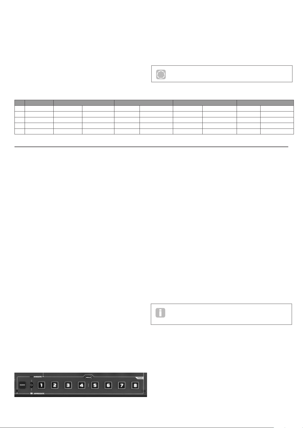
15. PADS 1 to 8: a set of eight backlit, multicolour, pressure-sensitive pads,
which may be used in two prim ary ways – A nimate or Arpeggiate. Additionally,
in conjunction with the FAVOR ITE button [17], they may be used as “Quick
Load” buttons to recall preferred patches.
16. ANI MAT E/A RP EGGIAT E switch: A 2-position switch (spring-loaded to
return-to-centre), which assigns the pads [15] to act as Animate controls or
Arpeggiator pads.
17. FAVORITE button: used to store and recall preferred patches in conjunction
with the eight pads [15].
18. HOLD button: modifies the action of a pad [15] in Animate mode by “locking”
it in an “On” state.
ARP section
19. ON: backlit button to switch the Arpeggiator on and off. W hen selected ‘On’,
the eight pads [15] enter Arpeggiator mode and the Arpeggiator LED in the
Pads section illuminates.
20. LAT CH button: applies the Arpeg giator ef fect to the last note(s) played
continuously, until a subsequent key is pressed. LATCH can be pre -selected
so that it is effective as soon as the Arpeggiator is enabled.
21. TEMPO control : sets the tempo of the Arpeggiator pattern being played. An
adjacent LED blinks to give a v isual indicati on of the tempo, and the actual
BPM value is displayed on the LCD.
Misc
22. Dynamic M ic Input : an XLR socket for the connection of the supplied
gooseneck microphone, or alternative dynamic microphone (i.e., a mic not
requiring phantom power to operate ). The mic can be us ed with the MiniNova’s
vocoder and VocalTune features, or routed to the audio outputs. This input is
overridden when a jack plug is plugged in to EX T IN {8 } on the rear panel.
23. MASTER VOLUME: the level control for the main audio outputs and the
headphone output.
24. OC TAVE + and – buttons: these transpose the keyboard up or down one
octave each time they are pressed. A ssociated multi-colour LEDs co nfirm that
a transposition has been applied.
4
Page 5
26
28
30
32
Rear view – connections
25. DC power connector: standard 2.2 mm socket for connecting the external
9 V DC PSU (supplied). See “Power requirements” on page 3.
26. On/off switch: 3-position switch:
POSITION ACTIO N
ext DC Enables external 9 V DC input
OFF Off
USB Enables power via USB port
27. USB port: Type B US B Type 1.1 (2.0-compatible) socket for connectio n to
PC or Mac
28. MIDI connectors: standard MIDI In/Out sockets (5-pin DINs)
G E T TI NG S TAR TE D
Standalone and computer operation – a foreword
The MiniNova may b e used as a standal one synthesizer, with or without MIDI connections
to/from other sound modules or keyboards. It may also be connected - via its USB port –
to a computer (Windows or Mac) running a DAW application. The MiniNova ca n then be
controlled entirely from the computer by using the MiniNova Editor plug-in. The MiniNova
Librarian is a separate software application, which greatly assists in the organising, saving
and rec all of patc hes.
25
27
29. Sustain pedal soc ket: 2-pole (mono) ¼” jac k socket for connection of a
sustain pedal. Both NO ( Normally Open) and NC (Normally Closed) pedal
types are comp atible ; if the pedal is connected when the MiniNova is p owered
on, the t ype will be automatically sensed during boot-up (provided your foot is
not on the pedal!). See “Parameter: Footswitch configuration” on page 13
for more information.
30. Headphones socket: 3-pole ¼” jack socket for stereo headphones. Phones
volume i s adjusted by the MASTER VOLU ME control [23 ].
31. OUTPUT LEFT and RIGHT: 2 x ¼” jack sockets carrying main stereo output.
Outputs are unbalance d, at +5 dBu maxi mum level .
32. EXT I N: ¼” jack socket for external instrument or line level audio inputs. This
input override s an XLR connector p lugged i nto the Dynamic Mic Input [22]
on the top panel. Input is balanced , and can accept a ma ximum input level of
0 dBu. The sensitivity of the input can be adjusted via the menu system (see
“Parameter: Input Gain” on page 12).
33. Kensing ton Lock Port: to secure your synthesizer.
29
31
33
STANDALONE OPERATION
– AUDIO AND MIDI
CONNECTIONS
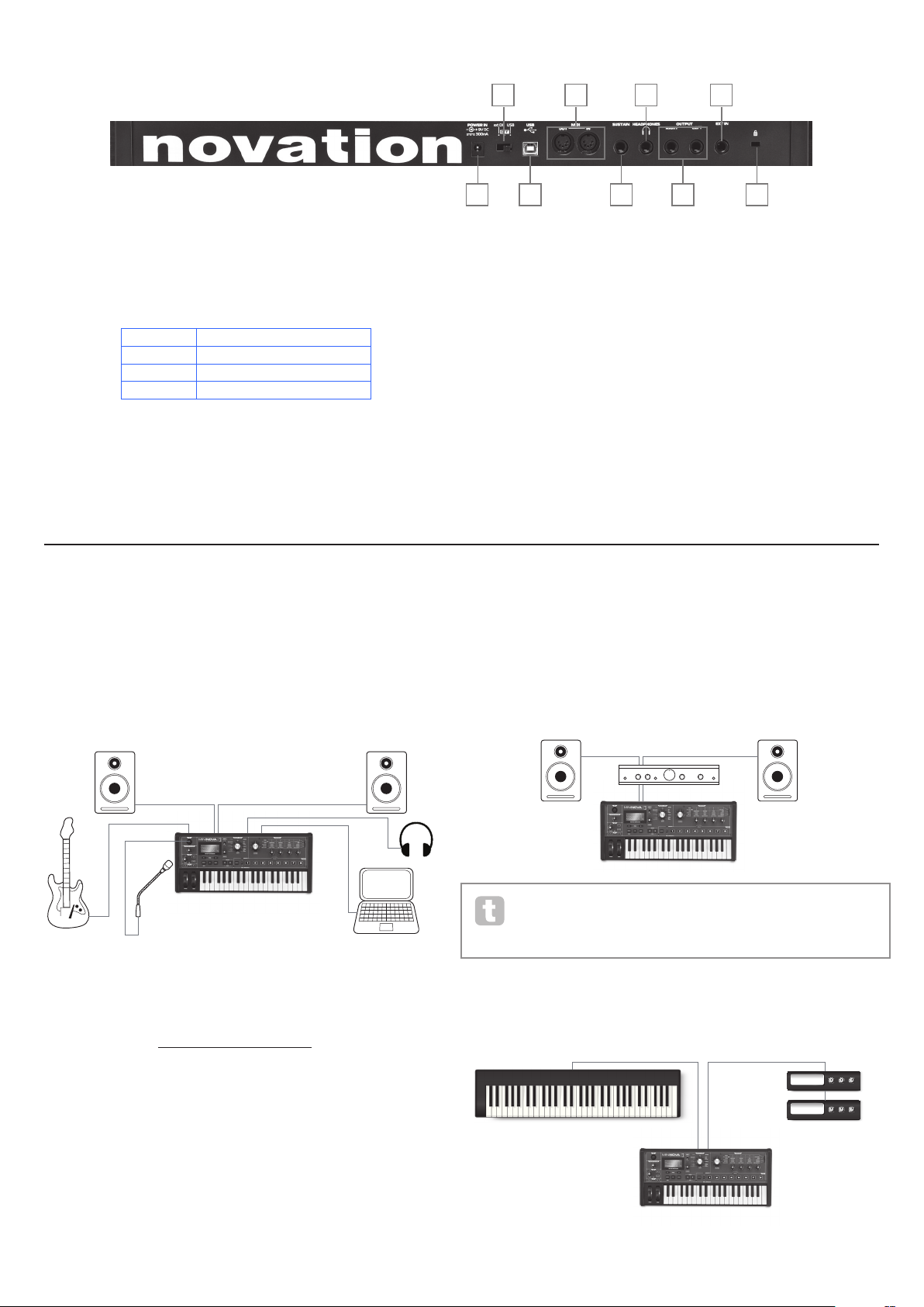
The simplest and quickest way of get ting sta rted with the MiniNova is to connect the two
rear pa nel jack sockets marked OUTPUT LEFT and RIGHT {31} to the inputs of a stereo
amplifier, audio mixer, powered speakers, third-party computer sound card or other means
of monitoring the output.
Audio Out
Audio In
USB
MiniNova connected to a computer via USB.
USB transmits MIDI to and from the computer
The various ways of connecting the MiniNova to accommodate the various methods of
working are covered in the documentation supplied with the MiniNova Editor and M iniNova
Libra rian software packages. The Installers for this software, and the related USB drivers
may be dow nloaded from http://novationmusic.com/support.
When us ing the MiniNova with the MiniNova Editor, an EDITOR flag is disp layed on the
LCD to con firm the connection. Also note that a USB flag is displayed when M iniNova is
connected to a computer via USB, and valid data interchange has been est ablished.
Audio Out
Note: the MiniNova is not a computer MIDI inter face. M IDI can be trans mitted
between the MiniNova synth and com puter via the USB connection, but MIDI
cannot be transferred b etween the computer and ex ternal equipment via the
MiniN ova’s MIDI DIN ports.
If using the MiniNova with other sound modules, connect MIDI OUT {28} on the MiniNova
to MIDI IN on the first sound module, and daisy-chain fur ther modules in the usual way. If
using the MiniN ova with a master keyboard, connect the controller’s MIDI OUT to
MIDI IN on the MiniNova, and ensure that the master keyboard is set to M IDI channel 1
(the MiniNova’s default channel).
Controller Keyboard
MIDI In
MIDI Out
Sound Modules
5
Page 6

With the amplifier or mixer off or muted, connect the AC adaptor to the MiniNova {25}, and
plug it into the AC mains. Turn the MiniNova on by moving the rear panel switc h {26} to
ext DC. After co mpleting its boot sequence, the LCD display will indicate the Patch which
has been loaded. If the TYPE/GENRE knob has not been moved since the last power-of f,
this will be the last Patch used. If the TYPE/GENRE knob has been moved, the Patch
loaded will be the lowest-numbered (or lowest alphabetically-sorted, depending on the
setting of the SORT switch) in the selected Type or Genre.
Turn on the mixer/amplifier/powered speakers, and turn up the Master Volume control
[23] until you have a healthy sound level from the speakers when you play the keyboard.
Using headphones
Instead of speakers via an amplifier and /or an audio mixer, you may wish to use a pair of
stereo headphones. These may be plugged into the rear panel headphone output socket
{30}. The main outputs are still active when headphones are plugged in. The MASTER
LEVEL control [23] also adjusts headphone level.
NOTE: The MiniNova headphone amp lifier is capable of outputting a high signa l level;
please take care when setting the volume.
A WORD ABOUT MENU
NAVIGATION
The MiniNova has been designed to give the player maximum control over sound character
and system operation with the minimum of hassle. The menu system is always entered by
pressing the MENU but ton [8 ]. The menu system consists of six individual menus :
Au dio In
Global
Arp
Chord
Ed it
Dump
Step bet ween the menus with the PAGE I and H buttons [7], and press OK [9 ] to enter the
desired menu. Use the PAGE buttons again to access the parameter you wish to change ;
use the D ATA control [6] to alter the parameter value.
The menu system can be exited by pressing the MENU/BACK button again; otherwise,
it will automatically time-out after a short period, and the screen will revert to display the
currently-loaded Patch information.
Scrolling through Patches
Your MiniNova comes pre-loaded with a set of facto ry Patches, which may be auditioned at
any time, providing you are not in the menu system. The Patches are arranged as 3 banks
(A to C), each with 128 patches ( 000 to 127). Ba nks A and B come pre-loaded with a full
set of fac tory Patches, while Bank C contains 128 copies of a n Initial Patch, which you can
either overwrite, or use as the basis for creating your own sounds. With the TYPE/GENRE
selector [4] set to ALL, either rotate the DATA control [6 ], or use the PATC H I and H
buttons [11] to step through the patches . The new sound is loaded as soon as the patch
data shows in the display.
Using the FAVORITE button to load Patches
You can assign up to eight of your favourite Patches to the eight Per formance Pads, and
then quickly reload them without needing to search through the whole Patch list .
Assigning a Patch to a Pad
With the Patch already loaded, pre ss and hold the FAVORITE button [17], and
simultaneously pres s and hold a Pad button. The display will show A ss ig nIn , with
a 3 second countdown timer. Af ter 3 seconds, the display changes to Favorite
A ss ign e d, and the Patch i s now assigned to that Pad. Note that the Pad turns red to
confirm the assignment.
Loading a Patch from a Pad
Press and hold the FAVORITE button; all the Pads will flash blue (unless the currentlyloaded Patch is one that was previously assigned to a Pad, in which c ase, the Pad shows a
steady red). W hile they are flashing, press the Pad which has the Patch you want ass igned
to it, and that Patch will now be loaded. The LCD will confirm the new Patch by name.
Demo Mode
Press the two PAT CH I and H buttons [11] simultaneously, and the M iniNova will enter
Demo Mode. Using any control will cause a bri ef description its function to be dis played
on the LCD screen. Note that none of the controls ( except m aster volume) or keyboard are
active in Demo Mode.
MODIFYING SOUNDS USING THE PERFORMANCE
CONTROLS
The MiniNova is equipped with a set of controls specifically designed for use in live
performanc e. These allow you to modify the sound of the loade d patch in a variety of
interesting and sometimes startling ways!
These controls are found in the PERFORM, PADS and ARP areas of the control panel
(see items 12 - 21 on page 4 ).
Parameter Controls
While playing li ve, it is of ten desi rable to manually adjust some aspect or other of the sound
– i.e., “ tweak” a particular parameter. Although the MiniNova’s des ign allows you to access
all the parameters defining a particular sound, it is useful if the most important par ameters
that you need while playing live are readily available, on a convenient set of c ontrols. These
are the four rotar y controls to the ri ght of the control pa nel, see item 12 on page 4.
Use these four knobs in conjunction with the Perform Row Selec tor switch [13]. A n
LED will illuminate to show you which of the six banks of available parameters the knobs
are assigned to. Note that Rows 3 to 6 always c ontrol the same pa rameters, regardles s of
the patch you have loaded – though the actual effect of the control will quite likely sound
different! Rows 1 and 2 place the four knobs into “Tweak” mode, where the parameters
they control var y with the patch (see below).
The Patch set can be browsed in either bank and numerical order, or alphabetically by
name, according the set ting of the SORT switch [5].
Searching through Types or Genres
Apar t from being arranged in 3 banks, the patches are also categorised for you ac cording
to the type of sound; this ma kes finding suitable sounds much ea sier. Eac h patch
belongs to both a Genre and a Type; the Genre broadly indicates the musical area for
which the patch might be suitable, the Type alternatively arranges the patches by sonic
characteristics. Use the TYPE/GENRE control to select the Type or Genre in which you
are interested.
Once the Type or Genre has been specifi ed, the patch set can again be browsed either in
numerical or alphabetical order.
The Genres and Types are listed below:
TYPES GENRES
All
Vocoder/VocalTune Rock/ Pop
Bass R&B/Hip Hop
Keyboard/Lead Dubstep
Pad/Strings House/Techno
Arp/ Movement D&B/Breaks
Classic Synth
6
Don’t worry too much at this stage what words like “Resonance” and “Sustain” mean – all
these ( and many other) terms are explained in much greater detail further on in the manual.
Just tr y to become familiar with the actual sonic effect you hear when you adjust each of the
parameters in turn, for di fferent catego ries of patch.
The four knobs used for “t weaking” will almost never be in the correct position
relative to the value of the parameter s they control which are stored as par t of the
currently-loaded Patch. For example, in the Patch A0 00 (“BassIsWet DC” ), the
value of the Filter Envelope Decay Time parameter is 27. If the Tweak control for this (RC2
in Row 4) is set to – say – 2 o’clock, the knob position implies a completely different value.
The LCD display includes two arrows which tell you which way to turn the knob to get the
knob position to “match” the stored parameter value. As long as Pot Pickup is set On (in
the Global Menu), the knob will have no effect until both arrows are off. If Pot Pickup is
Off, turning the knob will immediately alter the pa rameter, which may produce an audible
“jump”. Se e page 13 for more information on Pot Pickup.
r
Vocoder
Voc/MFX
r
n
n
u
u
T
T
Vocoder
Voc/MFX
r
n
u
T
Page 7
Rows 1 and 2 – Tweak and (FX) Tweak controls
With either Rows 1 or 2 selected, the knobs will have a different ef fect dep ending on
the patch loaded. This is because the actual assignment of the controls forms part of the
Patch. You will find that all the factory Patches have some Tweak Controls pre-assigned,
but you can change their function or add others if you wish.
NOTE: RC4 is preset to control the level of FX level when Row 2 ((F X) TWEAK) is
selected. However, this can be changed in the T WEAK s ubmenu of the EDIT menu.
* You will be ab le to find thi s – or any Patch yo u know by nam e – more quickly by set ting SOR T to A-Z
and scrolling through the listed Patches alphabetically.
The best way of understanding the Tweak controls is to load a patch and play with them. Try
loading the Patch “Synchromatic 1 P S”, which can be found in the Arp /Movement T YPE*.
Select the TWEAK row with the Perform Row Selec tor switch [13]. As you play, adjust
each of the four TWEAK controls in turn to hear their ef fect. You will find that you can
introduce fur ther variations to the sound. Now select the ( FX) TWEAK row; you’ll find that
the TWEAK controls now do something different and the sound can be modified in other
ways – in this case, by altering the audio effects processing applied to the sound.
Rows 3 to 6 – Fixed Tweak contr ols
The function of the four rotary controls is predeter mined when any of Rows 3 to 6 is
selected. The table below lists the functions, and tells you where to look in the User Guide
to find out m ore information on the parameter controlled in each case.
Full details of the parameters each of the Tweak controls in Rows 3 to 6 are
P
available at the page number indicated in the table below.
The imp ortant point to grasp here is that the effect of each TWEAK control on the sound
is spec ific to the patch. With different patches loaded, the TWEAK controls will alter
different sonic characteristics.
Row Group RC1 RC2 RC3 RC4
Parameter More Info? Parameter More Info? Parameter More Info? Parameter More Info?
Filter Resonance
3
Filter Envelope At tack
4
Amplitude Envelope Attack
5
Oscillator Osc1 Vir tual Sync
6
F1Re s pa ge 17
Flt At t pa ge 22
Am pAtt pa ge 20
O1V Sy n c p age 14
The Filter knob
Adjusting the frequency of the synth’s primar y filter ( Filter 1) is probably the most
commonly-used method of sound modification. For this reason, Filter 1 Frequency has
its own dedicated control in the form of a large rotary control [14] next to the parameter
controls. Ex periment with di fferent types of patch to hear how changing the filter frequency
alters the characteristic of different types of sound.
Using the Pads as performance controls
The eight Pads below the parameter controls have a number of functions on the MiniNova. In
this section, we are concerned only with their use as perfor mance controls . To enable the Pads
for per formance use, set the AN IM ATE /AR PEGGI ATE switch [16] to A NI MATE .
Like the T WEAK controls, the precise ef fect that each Pad w ill have on the characteristic
of the sound is Patch-dependent. Again, the best way of understanding what they can
do is to load a Patch and p lay with them. Load the Patch “Cry4Moon DF” - which can be
found in the Keyboa rd/ Lead T YPE* - and lightly touch each of the pads in turn while playing
norma lly. You’ll find that when you touch a pad, something distinctive ha ppens to the
sound. Try loading different types of Patch to see what ef fect the Pads have in each. Note
that not all Patche s have all ei ght Pads assigned.
Later in the manual, you will discove r how to reassign the Pads to make specifi c parameter
changes to any given patch, and that the se assignments remain with the patch for your
future use.
* You will be ab le to find thi s – or any Patch yo u know by nam e – more quickly by set ting SOR T to A-Z
and scrolling through the listed Patches alphabetically.
Trac kin g
Decay
Decay
Osc 1 Density
F1Tra c k pag e 17
FltDec pag e 22
AmpDec pa ge 20
O1Dense pa ge 15
Type
Sustain
Sustain
Osc 2 Vir tual Sync
F1Ty p e pa ge 17
FltSus page 22
AmpSus page 20
O2VSync pag e 14
The L ATCH button plays the currently selecte d arp sequence repeatedly without the keys
being held. LATC H can also be pressed before the Arpeggiator is enabled. When the
Arpeggiator is enabled, the MiniNova will immediately play the arp sequence defined by the
last set of notes played, and will do so indefinitely. The tempo of the ar p sequence is set by
the TEMPO control; you can make the sequence play faster or slower by altering this. See
page 13 for further details.
The Vocoder
Your MiniNova comes with a Vocoder section, whic h allows you to create some really great
sounds by combining synth sounds with either a voice or another instrument such as a guitar.
To use the Vocoder, rst connect a microphone (one is supplied with your MiniNova) to the
MIC socket [22] on the top panel. A lternatively, you can plug a guitar or other instrument
into the E XT IN socket {8 } on the rear panel ( this will disconnect the mic socket). Nex t,
you need to set the audio gain of the mic or instrument. To do this, press MENU [8], select
Audio In using the DATA wheel [6] , then pre ss OK [9] . This will open the menu system,
and Audio In is the first menu displayed . The first menu item in the Audio Menu is Input
Gain (In pt Gain); ad just the input gain with the D ATA wheel [6] while noting the signal
level as displayed at the top of the LCD screen as a horizontal bargraph meter. Ensure that
the loudest audio level does not cause the OVER segment to illuminate.
Set the TYPE/GENRE control [4] to VOCODER/VOCALTUNE, and select a patch from
the available subset. Now hold one or more keys down and sing into the microphone (or
play the instrum ent connected at E XT IN ). You will hear the sound of the synth, modified by
the external audio input. As with a ny other patch, you can alter various parameter s with the
FI LTE R and four rotar y encoders in the PERFORM section, or use the Animate functions
as described above.
Drive
Amount
Release
Osc 2 Density
F1Damnt pag e 17
F1Env2 p age 17
Am p R el page 21
O2Dense page 15
The Arpeggiator
The MiniNova has a powerful Arpeggiator feature which allows arpeggios of varying
compl exity and rhythm to be played and manipulated in real-time. If a single key is pressed,
the note will be retriggered by the Arpeggiator. If you play a c hord, the Arpeggiator
identifies its notes and plays them individually in sequence (this is termed an arpeggio
pattern or ‘arp se quence’); thus if you play a C major triad, the selected notes will be C, E
and G.
The MiniNova Arpeggiator is enabled by pre ssing the ARP ON button [19]; its backlight
will confirm and the eight Pads will turn red. H olding a note down will repeat the note in
the sequence, a nd you will see the Pads’ illumination changing to purple a s the pattern
progresses. Initially all enabled beats in the sequenc e are sounded, but if you pres s a Pad,
the beat corres ponding to that Pad’s position will now be omitted from the sequence,
generating a rhy thmic pattern. The ‘deselected’ Pads will not illuminate. A ‘deselected’ Pad
may be re-enabled by tapping it a second time.
Arpeggiator operation in the MiniNova is controlled by the three ARP buttons [19], [20] &
[21]: ON, LAT CH and TEMPO. The ON button enable s or disables the Arpeggiator.
As with all the other performance controls, we recommend that there is no substitute for
experimentation to get an understanding of how the various controls interact.
Note that two of the factor y Vocoder Patc hes, “Aaah 1” (B073) and “Aaa h 2” (B074),
do not make use of the built-in mi cropho ne. Although these use the M iniNova’s
Vocoder functions, they use xed formants which are stored with the Patches.
Pitch and Mod wheels
The MiniNova is fitted with a standa rd pair of synthesizer control wheels adjac ent to the
keyboard, PITCH and MOD ( Modulation ). The PITCH control is spring-loaded and always
returns to the centre position.
Moving PITCH will always raise or lower the pitch of the note( s) being played. The range of
operation can b e set via the menu system, from a semitone to an octave, in semitone steps.
The MOD whee l’s precise function varies with the Patch loaded; it is used in general
to add expression or various elements to a synthesise d sound. A c ommon use is to add
vibrato to a sound; another is to control the speed of a “vir tual” rotary speaker.
It is possible to a ssign the MOD wheel to control any p arameter constituting the sound
– or a combination of parameters simultaneously. This topic is discussed in more detail
elsewhere in the manual. See “Wh at is Legato?” on page 21.
7
Page 8
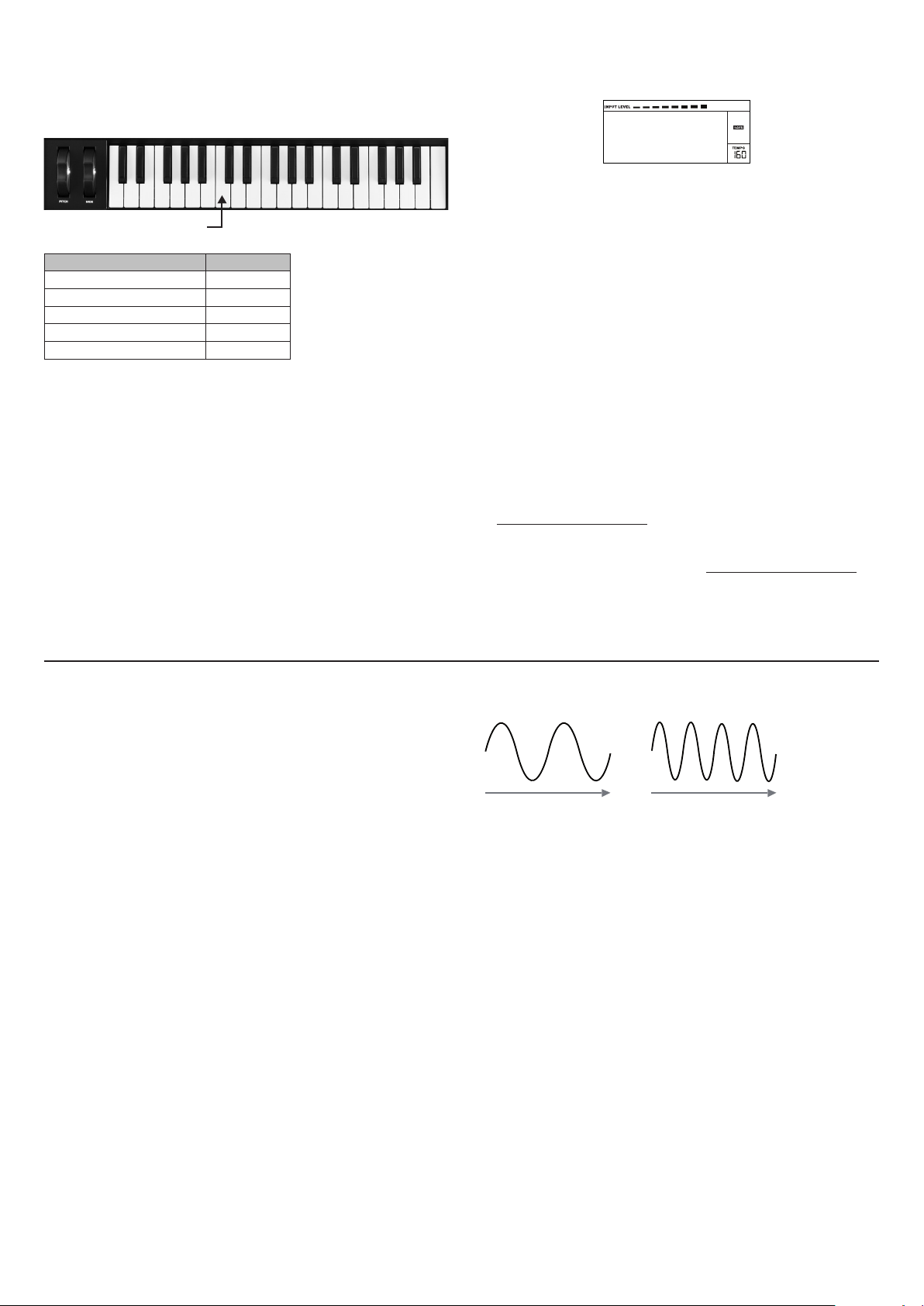
Octave Shift
Time Time
A B
These two backlit buttons [24] transpose the keyboard up or down one octave each time
they are pressed, to a maximum of four octaves . The colour displayed by the buttons
indicates the number of octaves shi fted: when both LEDs are off (the default state), the
lowest note on the keyboard is one octave b elow Mid dle C.
Middle C
SHIFT COLOUR
(no buttons pressed) LEDs off
± 1 octave Red
± 2 octaves Magenta
± 3 octaves Purple
± 4 octaves Blue
Normal keyboard pitch may be reinstated at any time by pressing both Octave buttons
together.
Storing a Patch
Novation have worked hard to create a really useful and great-sounding set of factory
Patches, and we are sure that many of them will meet your needs without further
modifi cation. However, the scope for altering – or creating comp letely new - sounds in the
MiniN ova is almost limitless, and when you have done so, you will probably want to save the
sounds for future use.
It is possible to store or write your own patches directly into the MiniNova without using
the MiniNova Editor and Librarian software applications. Once any of the pa rameters of a
Patch have been cha nged, the SAVE flag will illuminate in the LCD, to re mind you that you
are no longer working with an unmodified Patch. To save the modified Patch:
1. Press the SAVE button [10] , which will display the name that the Patch had
when it was first loaded.
NOTE: The Memory Protect function is active by default, so you are likely to see the words
Memory Protect ! flash on-screen. It will not be possible to save a modifie d version of the
current patch, without turning this option off. See “Parameter: Memory Protection” on
page 12.
Memory
Protect
Note that the screen will prompt you for a new name for the modified vers ion (Nam e?), and
that the current name will b e offered as a suggestion, with the first character flashing . Use
the DATA control [ 6] or the PATCH I and H but tons [11] to select a different alphanumeric
character.
• Use the PAG E I and H buttons [7] to move to the next character, and continue in this
manner until the new name ha s been entered.
• Press SAVE aga in. You will now be prompted to choose the location where the new
Patch is to be saved. The location of the original Patch will be offered as the default;
if you choose this , the original patch data will be overwritten. Use the D ATA control
[6], or PATCH I and H buttons [11] to select a different loc ation. N ote that Bank C
(128 locatio ns) has been lef t empty for you to save your own patches; thi s avoids
overwriting any of the original versions.
• Press SAVE aga in, and you will now be p rompted to choose the TYPE Category
that will allow MiniNova’s sorting system to retrieve it. Use the DATA control to select
the most appropriate one, and press SAVE again.
• You will finally be prompted to choose the GENRE for filing purposes. Use the DATA
control to select the most appropriate, and press SAVE again.
• The scr een will now confir m the new Patch with the message
Patch Saved. Note that whichever location is chosen for the new Patch, any
Patch data already saved to th at location will be lost.
NOTE: A faster method of managing patches (writing, loading, renaming, reordering etc.)
is by using the downloadable MiniNova Librarian. This can be downloaded free of charge
from www.novationmusic.com/support.
Updating the MiniNova’s Operating System
OS update files will be available from time to time at www.novationmusic.com/support in
the form of a MIDI SysEx file. The update proc edure requires the MiniNova to be connected
via USB to a computer which has first had the necessar y USB drivers installed . Full
instructions on performing the update will be supplied with the download.
SYNTHESIS TUTORIAL
This section covers the subject of sound generation in more detail and discusses the
various basic features available in the MiniNova’s sound generation and processing blocks.
It is recommended that this chapter is read carefully if analogue sound synthesis is an
unfamiliar subject. Users familiar with this subject can skip this chapte r and move on to the
next chapter.
To gain an understanding of how a synthes izer generates sound it is helpful to have an
appreciation of the components that make up a sound, both music al and non-musical.
The only way that a sound may be detected is by a ir vibrating the eardrum i n a regula r,
perio dic manner. The brain interprets these vibrations (very accurately ) into one of an
infinite number of different types of sound.
Remar kably, any sound may be described in ter ms of just three properti es, and all sounds
always have them. They are:
• Pitch
• Tone
• Volume
What makes one sound different from anothe r is the relative magnitudes of the three
properties a s initially present in the sound, and how the properties change over the
duration of the sound.
With a musical sy nthesizer, we deliberately set out to have precise control over these three
properties a nd, in particular, how they can be changed during the “li fetime” of the sound.
The properti es are of ten given different names: Volume may be refer red to as Amplitude,
Loudness or Level, Pitch as Frequency and Tone as Timbre.
Pitch
As state d, sound is perceived by air vibrating the ear drum. The pitch of the sound is
determined by how fast the vibratio ns are. For an adult human, the slowest vibration
perce ived as sound is about twent y times a second, w hich the b rain interprets as a bass
type sound; th e fastest is many thousands of times a second, w hich the b rain interprets as
an high treble type sound.
If the number of pe aks in the t wo waveforms (vibrations) are counted, it will be seen that
there are exactly twice as many peaks in Wave B as in Wave A. (Wave B is actually an
octave higher in pitch than Wave A). It is the number of vibrations in a given period that
determines the p itch of a sound. This is the reason that pitch is sometimes referred to as
frequency. It is the number of waveform peaks counted during a given period of time which
defines the pitch, or frequency.
Tone
Musical sounds consist of several different, related pitches occurring simultaneously. The
lowest is referred to as the ‘ fundamental’ pitch and c orresponds to the perceived note of
the sound. Other pitches making up the sound which are related to the fundamental in
simple mathematical r atios are called harmonics. The relative loudness of each h armonic
as compared to the loudness of the fundamental determines the overall tone or ‘timbre’ of
the sound.
Consider two instruments such as a harpsichord and a piano playing the same note on the
keyboard and at equal volume. Despite having the same vo lume and pitch, the instruments
still sound distinctly different. This is because the different note-ma king mechanisms of
the two instruments generate dif ferent sets of harmonics; the har monics present in a piano
sound are different to those found in a harpsichord sound.
Volume
Volume, w hich is of ten referred to as the amplitude or loudness of the sound is determined
by how large the vibrations are. Very s imply, listening to a piano fro m a metre away would
sound louder than if it were fifty metres away.
8
Page 9
A B
Volume
Harmonic
1
Sine Wave
Square Wave
Volume
Harmonic
1 2 3 4 5
Volume
Harmonic
1 3 5 7
Triangle Wave
Volume
Harmonic
1 3 5 7
Triangle Wave
Volume
Harmonic
1
Sine Wave
Sawtooth Wave
Volume
Harmonic
Square Wave
Volume
Harmonic
1 2 3 4 5
Volume
Harmonic
1 3 5 7
Triangle Wave
1 2 3 4 5
Square Wave
Volume
Harmonic
1 2 3 4 5
Volume
Harmonic
1 3 5 7
Triangle Wave
Sawtooth Waves
Volume
Having shown that just three elements may defi ne any sound, these elements now have to
be related to a Musical synthesizer. It is logical that a different section of the Synthesizer
‘synthesizes’ (or creates) these different elements.
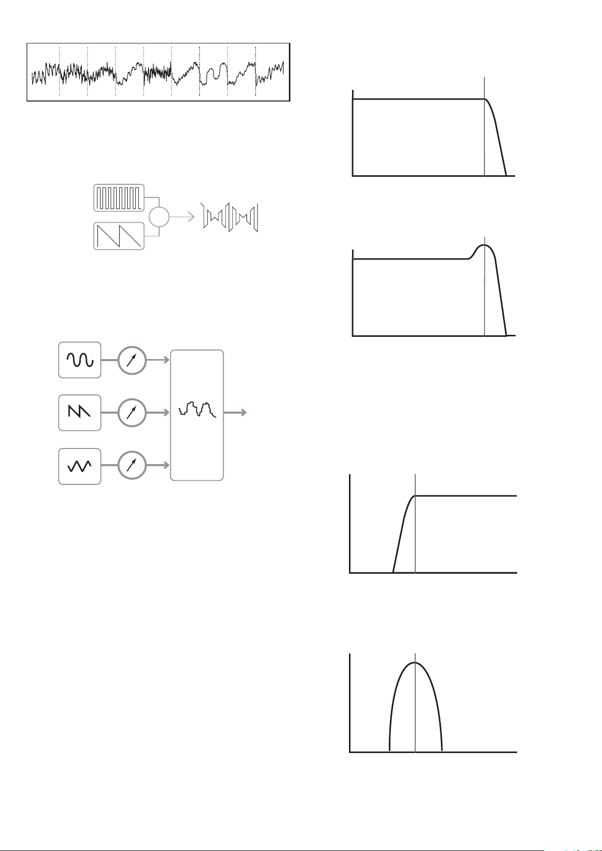
One sec tion of the synthesizer, the Oscillators, provide raw waveform signals whi ch
define the pitch of the sound along with its raw harmonic content (tone). These signals
are then mixed together in a section called the Mixer, and the resulting mixture is then fed
into a section called the Filter. This m akes fur ther alterations to the tone of the sound, by
removing (filtering) or enhancing cer tain of the harmonics. Lastly, the filtere d signal is fed
into the Amplifier, which determines the final volume of the sound.
Oscillators Mixer Filter Amplifier
Additional synthesizer sections - LFOs and Envelopes - provide further ways of altering the
pitch, tone and volume of a sound by interacting with the Oscillators, Filter and
Ampli fier, providing changes in the character of the sound which can evolve over time.
Because LFOs’ and Envelopes’ only purpose is to control (modulate) the other
synthesizer sections, they are commonly known as ‘modulators’.
These various synthesizer sections will now be covered in more detail.
Volume
Sawtooth Wave
1 2 3 4 5
Harmonic
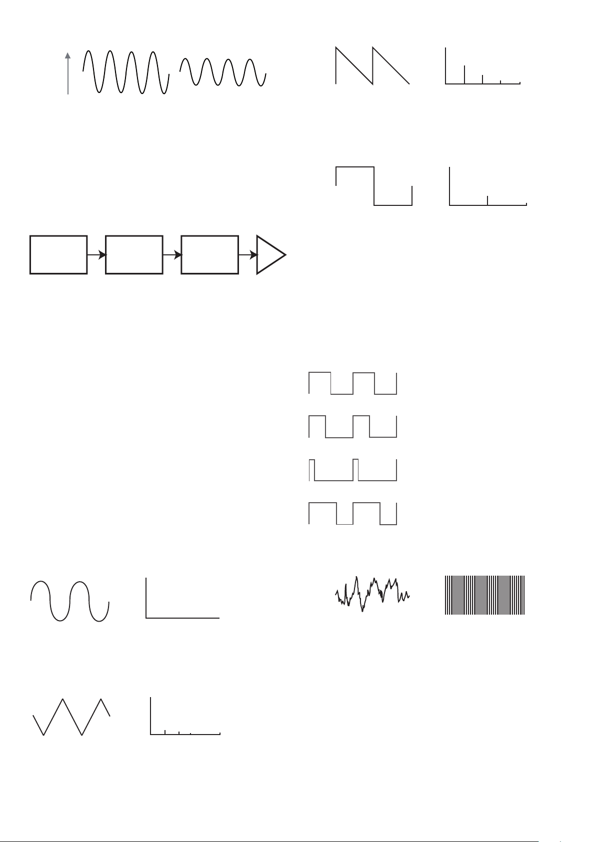
These are rich in harmonics, and containing both even and odd harmonics of the
fundamental frequency. The volume of each is inversely proportional to its position in the
harmonic series.
Square / Pulse Waves
Volume
Square Wave
1 2 3 4 5
Harmonic
These only have odd harmonics, which are at the same volume as the odd harmonics in a
sawtooth wave.
It will b e noticed that the square waveform spends equal amounts of time in its ‘high’ state
and its ‘low’ state. This ratio is known as the ‘duty cycle’. A square wave always has a duty
cycle of 50% which means it is ‘high’ for half the cycle and ‘ low’ for the other ha lf.
In the MiniNova , it is possible to adjust the duty cycle of the basic square waveform to
produce a waveform which is more ‘rectangular’ in shape. The se are often known as Pulse
waveforms. As the waveform becomes more and more rectangular, more even harmonic s
are introduced and the waveform changes its character, becoming more ‘nasal’ sounding.
The width of the pulse waveform (the ‘Pulse Wi dth’) can be altered dynamically by a
modulator, which results in the harm onic content of the waveform co nstantly changing. Thi s
can give the waveform a very ‘ fat’ quality when the pulse width is altered at a moderate rate.
The Oscillators And Mixer
The Oscillator is really the hear tbeat of the Synthesizer. It generate s an electronic wave
(which creates the vibrations when eventu ally fed to a loudspeaker). This Waveform is
produced at a controllable musical pitch, initially determined by the note played on the
keyboard or contained in a received MIDI note message. The initial distinctive tone or
timbre of the waveform is actually determined by the waveform’s shape.
Many years ago, pioneer s of music al synthesis dis covered that just a few distinctive
waveforms contained many of the most useful harmonics for mak ing musi cal sounds. The
names of these waves reflec t their actual shape when viewed on an instrument called an
Oscilloscope, and the se are: Sine waves , Square waves, Saw tooth waves, Triangle waves
and Noise.
Each waveform shape (exc ept noise) has a specific set of musically-related harmonics
which can be manipulated by further sections of the synthesizer.
The diagrams below show how these waveforms look on an oscilloscope, and illustrate
the relative levels of their harmonics. Remember, it is the relative levels of the various
harmonics present in a waveform which deter mine the tone of the final sound .
Sine Waves
Sine Wave
These possess just a single harmonic. A sine waveform produces the “purest” sound
because it only has its single pitch (frequency).
Triangle Waves
Triangle Wave
These contain only odd harmonics. The vo lume of each decre ases as the square of its
position in the harmonic series. For example, the 5th harmonic has a volume 1/25th of the
volume of the fundamental.
Volume
Volume
1
Harmonic
1 3 5 7
Harmonic
50%
a pulse waveform sounds whether the
duty cycle is 40 % or 60%, since the
waveform is just “inverted” and the
harmonic content is exactly the same.
It does not make any difference to how
40%
10%
60%
Noise Waves
Volume
1 2 3 4 5
These are basically random signals, and have no one fundamental frequency (and therefore
no pitch proper ty). A ll frequencies are at the same volume. Because they possess no pitch,
noise signals are often useful for creating sound effects and percussion type sounds.
Digital Waveforms
In addition to the traditional types of Oscillator waveforms detailed above, the MiniNova
also offers a set of carefully selected, digitally-generated waveforms containing useful
harmonic elements normally difficult to produce using traditional Oscillators.
Wavetable s
A “wavetable” is es sentia lly a group of digital waveforms. The MiniNova’s 36 wavetables
each contain 9 separate di gital waveforms. The benefit of a wavetable is that consecutive
waveforms in the wavetable can be blended. Some of the MiniNova’s wavetables contain
waveforms with similar harmonic content, while others contain waveforms with greatly
differing harmonic content. Wavetables come ali ve when the ‘wavetable index’ – the
position within the wavetable - is mo dulated , resulting in a sound that continually changes
character, either smoothly or abruptly.
9
Page 10
9 Waves make up a wave table
OSC 1
OSC 3
X
Volume
Frequency
Cut-off
Frequency
Volume
Volume
Frequency
Cut-off
Frequency
Volume
Frequency
Cut-off
Frequency
Frequency
Cut-off
Frequency
Volume
Volume
Frequency
Cut-off
Frequency
Frequency
Cut-off
Frequency
OSC 1
OSC 1 VOLUME
OSC 2 VOLUME
OSC 3 VOLUME
COMPLEX
WAVEFORM
MIX OF
OSC1, 2 AND 3
MIXER
INPUT TO
FILTER
OSC 2
OSC 3
Ring Modulation
A Ring Modulator is a sound generator that takes signals from two of the MiniNova’s
oscillators and effectively “multiplies” them together. The MiniN ova has 2 Ring Modulators,
one takes Osc 1 and Osc 3 as inputs, and th e other takes Osc 2 and Osc 3. The resulting
output depends on the various frequencies and harmonic content present in each of the
two oscillator signals , and will consist of a series of sum and difference frequencies as well
as the frequencies present in the original signals.
actually be used for some sounds as an additional sound source i f wished.
The diagram below shows th e response of a typical low pass filte r. Frequencies above the
cut-off point are reduced in volume.
Cut-off
Frequency
Volume
Frequency
When re sonance is added, frequencies at the cut-off point a re boosted in volum e.
Cut-off
Frequency
The Mixer
To extend the range of sounds that may be produced, t ypica l analogue synthesizers have
more than one Oscillator. By using multiple Oscillators to create a sound, it is possible
to achieve very interesting harmonic mixes. It is also possible to slightly detune individual
Oscillators against each other, which creates a very warm, ‘fat’ sound. The MiniNova’s
Mixer a llows mixing of three indep endent O scillators, a separate Noise Oscillator and two
Ring Modulator sources.
The Filter
The MiniNova is a subtractive music synthesizer. Subtractive implies that par t of the sound
is subtracted somewhere in the synthesis process.
The Oscillator s provide the raw waveforms with plenty of harmonic content and the F ilter
section subtracts some of the harmonics in a controlled manner.
14 types of Filter are availabl e on the MiniNova, though these are varieties of three basic
filter types: L ow Pass, Band Pass and High Pass. The type of Filter most commonly
found on synthesizers is the Low Pass type. With a Low Pass Filter, a cut-off point
(or cut-off frequency ) is chosen and any fr equencies below the point are passed, and
frequencies a bove are filtered out. The set ting of the Filter Frequency parameter dictates
the point below which frequencies are removed. This process of removing harmonics
from the waveforms has the ef fect of changing the sound’s character or timbre. When the
Frequency parameter is at maximum, the filter is completely “open” and no frequencies ar e
removed from the raw Oscillator waveforms.
In prac tice, there is a gradual (rather th an a sudden) reduction in the volume of the
harmonics above the cut-off point of a Low Pass Filter. How rapidly these harmonic s
reduce in volume as frequency increases a bove the cut-off point is determined by the
Filter’s slope. The slope is measured in ‘volume units per oct ave’. Since Volume is
measured in decibels , this slope is usually quoted as so many decibels per octave
(dB /oct) . Typical va lues are 12 dB/oct and 24 dB/oct. The hi gher the number, the g reater
the rejection of harmonics above the cut-of f point, and the more pronounced the filtering effect.
A further important parameter of the Filter is its Re sonance. Frequencies at the cut-off point
may be increased in volume by the Filter Resonance control. This is useful for emphasizing
cert ain harmonics of the sound.
Volume
Frequency
In addition to the traditional Low Pass Filter type, there are also High Pass and B and Pass
types. The ty pe of Filter used is selected with the Filter Type parameter.
A High Pa ss Filter is similar to a Low Pass Filter, but works in the “opposite sense”, so that
frequencies b elow the cut-off point are removed. Frequencies above the cut-off point a re
passed. When the Filter Frequency parameter is set to zero, the filter is completely open
and no frequencies are removed from the raw Oscillator waveforms.
Cut-off
Frequency
Volume
Frequency
When a Band Pass F ilter is used, only a narrow band of frequencies centered around the
cut- off point are p assed. Frequencies above and below the band are removed. It is not
possible to fully open this type of F ilter, and allow all frequencies to pas s.
Cut-off
Frequency
Volume
Frequency
As Resonance is increased, a whistling-like quality will be introduced to the sound passing
through the filter. When set to very high levels, Resonance actually causes the filter to
self-oscillate whenever a signal is being passed through it. The resulting whistling tone
being produced is actually a pure sine wave, the pitch of which depends on the setting of
the Frequency control (the filter’s cut-off point). This re sonance-produced sine wave can
10
Envelopes And Amplifier
In earlier paragraphs, the synthesis of the pitch a nd the timbre of a sound were described.
The nex t part of the Synthesis Tutorial describes how the volume of the sound is controlled.
The volume of a note created by a musical instrument often varies greatly ove r the duration
Page 11
KEY "ON" KEY "OFF"
TIME
KEY "ON" KEY "OFF"
VOLUM E
KEY "ON" KEY "OFF"
TIME
KEY "ON" KEY "OFF"
VOLUM E
TIME
KEY "ON" KEY "OFF"
VOLUM E
TIME
KEY "ON" KEY "OFF"
VOLUM E
ATTACK DECAY RELEASE
TIME
KEY "ON" KEY "OFF"
VOLUM E
TIME
KEY "ON" KEY "OFF"
VOLUM E
KEY "ON" KEY "OFF"
ATTACK DECAY RELEASE
SUSTAIN
TIME
KEY "ON" KEY "OFF"
VOLUM E
TIME
KEY "ON" KEY "OFF"
VOLUM E
ATTACK DECAY
RELEASE
SUSTAIN
SUSTAIN
RATE
TIME
KEY "ON" KEY "OFF"
VOLUM E
ATTACK DECAY
RELEASE
SUSTAIN
SUSTAIN TIME
TIME
KEY "ON" KEY "OFF"
VOLUM E
ATTACK DECAY RELEASE
SUSTAIN
TIME
KEY "ON" KEY "OFF"
VOLUM E
TIME
PITCH
of the note, according to the t ype of instrument.
For example, a note played on a n Organ quickly attains full volume when a key is pressed.
It stays at full volume until the key is released, at which point the volume level falls instantly
to zero.
VOLUM E
TIME
A Piano note quick ly attains full volume after a key is pre ssed, and gradually falls in volume
to zero af ter several seconds, even if the key is held.
VOLUM E
TIME
A String Section emulation only at tains full volume gradually when a key is pressed. It
remains at full volume while the key is held down, but once the key is released, the volume
falls zero fairly slowly.
KEY "ON" KEY "OFF"
VOLUM E
The MiniNova’s second Envelope Generator ( Env 2) is used to modify the filter cut-off
frequency over the lifetime of a note.
In the MiniNova , Envelope Generators 3 to 6 can be used for special purposes, such as
modulating the Wavetable index or FX levels.
KEY "ON" KEY "OFF"
FILTER
CUT-OFF
SUSTAIN
ATTACK DECAY RELEASE
TIME
LFOs
Like the E nvelope G enerators, the LFO section of a synthesizer is a Modul ator. Thus
instead of being a part of the sound synthesis itself, it is used to change (or modulate)
other sections of the synthesizer. For example, an LFO c an be used to alter Oscillator pitch,
or Filter cut-off frequency.
Most musical instruments produce sounds that vary over time both in volume and in pitch
and timbre. Sometimes these variations can be quite subtle, but still contribute greatly
towards characterising the final sound.
Where as an Envelope is used to control a one-off modulation during the lifetime of a
single note, LFOs modulate by using a repeating cyclic waveform or pattern. As discussed
earli er, Oscillators produce a constant waveform which can take the shape of a repeating
sine wave, triangle wave etc. LFOs produce waveforms in a similar way, but norma lly at a
frequency which is too low to produce a sound that the human ear could perceive. (In fact,
LFO stands for Low Frequency Oscillator.)
As with an Envelope, the waveforms generated by the LFOs may be fed to other parts of
the synthesizer to create th e desired changes over time – or ‘movements’ - to the sound.
The MiniNova has three independent LFOs, which m ay be used to m odulate different
synthesizer sections and can run at different speeds.
A typical waveshape for an LFO would be a Triangle wave.
In an analogue synthesizer, changes to a sound’s character which occur over the duration
of a note are controlled by a section called an Envelope Generator. The MiniN ova has 6
Envelope Generators (called Env 1 to Env 6). Env 1 is always related to an Amplifier, which
controls the note’s amplitude – i.e., the volume of the sound - when the note is playe d.
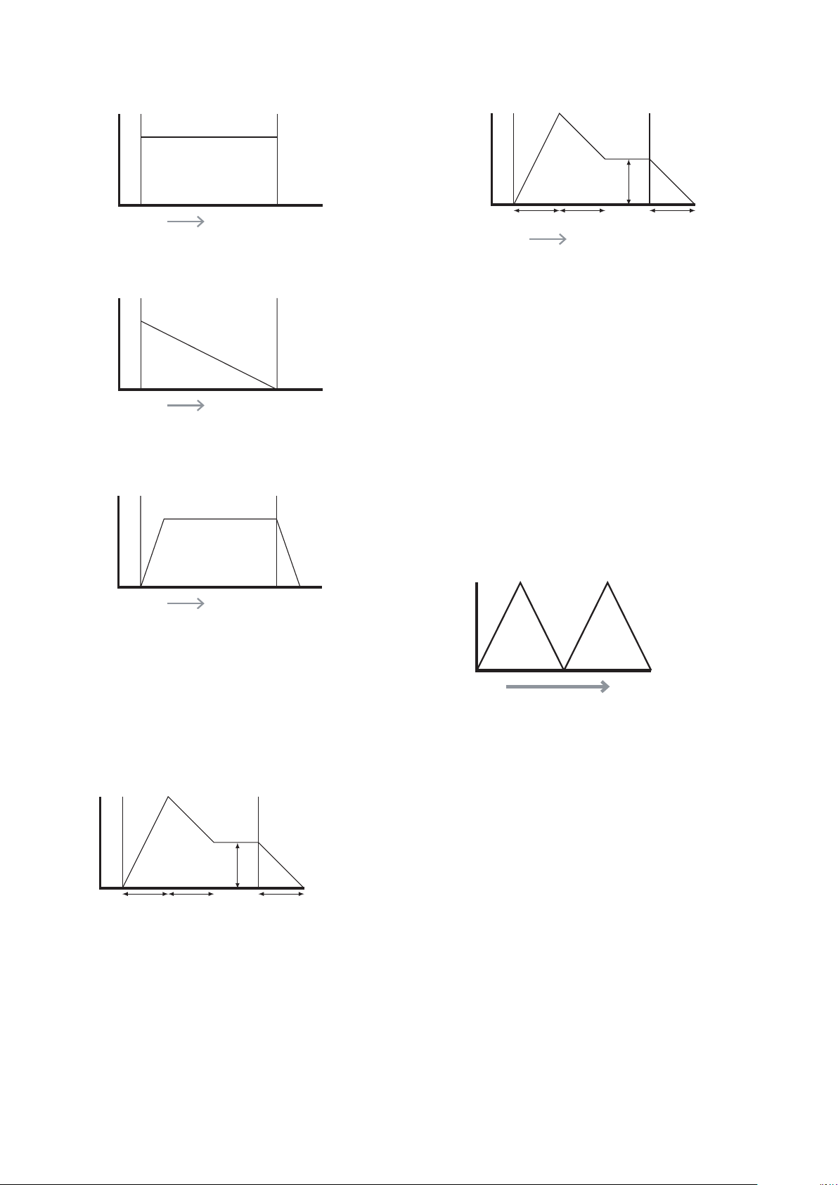
Each envelope generator has four main controls which are used to adjust the shape of the
envelope.
Attack Time
Adjusts the time it takes af ter a key is pressed for the volume to climb from zero to full
volume . It can be u sed to create a sound with a slow fade-in.
TIME
VOLUM E
SUSTAIN
Decay Time
Adjusts the time it takes for the volume to fall from its initial full volume to the level set by the
Susta in control while a key is held down.
Sustain Level
This is unlike the other Envelope controls in that it sets a level rather than a period of tim e.
It sets the volume level that the envelope remains at while the key is hel d down, af ter the
Decay Time has ex pired.
Release Time
Adjusts the time it takes for the volume to fall from the Sust ain level to zero once the key is
relea sed. It c an be used to create sounds that have a “fade-out ” quality.
A typical synthesizer w ill have one or more envelopes . One envelope is always applied to
the amplifier to shape the volume of each note played. Additional envelopes can be used to
dynamically alter other sections of the synthesizer during the lifetime of each note.
Imagine this very low frequency wave being applied to an Oscillator’s pitch. The result is
that the pitch of the Oscillator slowly rises and falls above and below its original pitch. This
would si mulate, for example, a violinist moving a finge r up and down the string of the
instrument whilst it is being bowed. This subtle up and down movement of pitch is referred
to as the ‘Vibrato’ effect.
Alternatively, if the same LFO signal were to modulate the Filter cut-off frequency instead of
the Oscillator pitch, a familiar wobbling effect known as ‘wah- wah’ would be result.
As well as setting up various sections of the synthesizer to be modulated by LFOs,
additional Envelopes may also be used as modulators at the same time. Clearly, the more
Oscillators, Filters, Envelopes and LFOs there are in a synthesizer, the more powerful it is.
Summary
A synthe sizer can be broken down into five main sound generating or sound modifying
(modulating) blocks.
1. Oscillators that generate waveforms at a various pitches.
2. A Mixer that mixes the outputs from the Oscillators together.
3. Filters that remove certain harmonics, changing the character or timbre of the sound.
4. An Amplifier controlled by an Envelope generator, which alters the volum e of a sound
over time when a note is played.
5. LFOs and Envelopes that can be used to modulate a ny of the above.
Much of the enjoyment to be had with a Synthesizer is with experimenting with the factory
preset sounds and creating new ones. There is no substitute for ‘hands on‘ experience.
Expe riments with adjusting the MiniNova’s many parameter s will eventually lead to a fuller
under standing of how the various c ontrols alter and h elp shape new sounds.
Armed with the knowledge in this chapter, and an understanding of what is actually
happe ning in the machine when tweaks to the knobs and switches are made, the process
of creating new and exciting sounds will become easy - Have fun.
11
Page 12
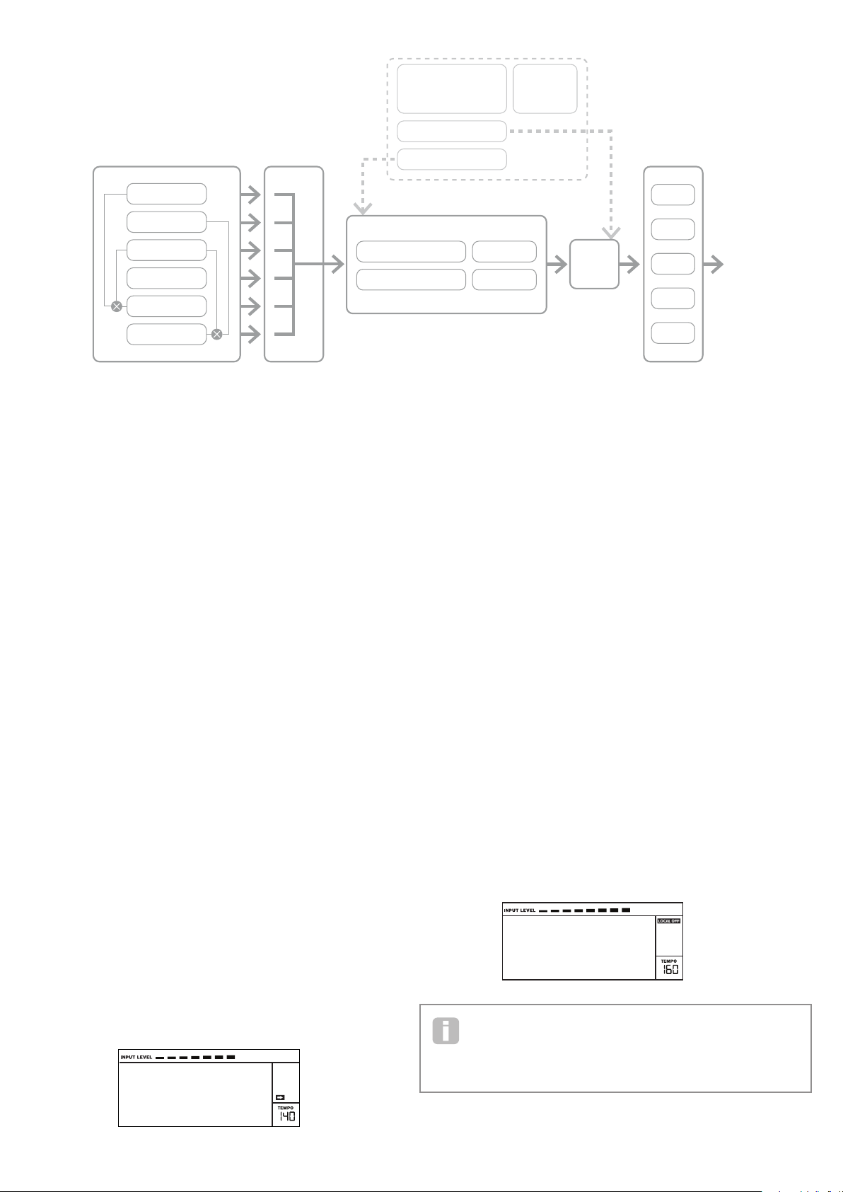
SIMPLIFIED MININOVA
BLOCK DIAGRAM
MIXE R
OSCILLATOR 1
ENVELOPES 3 - 6 LFO 1 - 3
ENVELOPE 1
ENVELOPE 2
FX 1
OSCILLATOR 2
OSCILLATOR 3
NOISE
RING MOD 1*3
RING MOD 2*3
FILTER 1 DISTORTION
FILTER 2 DISTORTION
SYNTH MENUS –
REFERENCE SECTION
This part of the User Guide gives you a detailed description of every par ameter available
for adjustment in the Mini Nova. As previously explained, all adjustments to p atches – other
than those made via the controls in the Perform and Pads sec tions of the top panel – are
made via the MiniNova’s comprehensive menu structure. The menus also include “System”
or setup options, such as patch dumping, keyboard setup, and so on.
The structure is “context-sensitive” – this m eans that you will be offered a range of options
which is dependent on what it is you are trying to do.
The menu system is a lways ente red by pressing the MENU button [8]. The menu system
consists of six individual menus:
Au dio In
Global
Arp
Chord
Ed it
Dump
Step bet ween the menus with the PAGE I a nd H buttons [7], and press OK [9] to enter the
desired menu. Use the PAGE buttons again to access the parameter you wish to change ;
use the D ATA control [6] to alter the parameter value.
The menu system can be exited by pressing the MENU/BACK button again; otherwise,
it will automatically time-out after a short period, and the screen will revert to display the
currently-loaded Patch information.
NOTE: The Default value s shown for each parameter apply to Initial patche s; other
factor y Patche s will have different value s as part of the Patch definition.
Top Menu: Audio In
Parameter: Input Gain
Displayed as: Inp tGain
Default value: +20 dB
Range of adjustment: -10 dB to +65 dB, O ff
This control adjusts gain for the Audio input. The gain is displayed directly in dBs. As the
gain is increased, the signal at the input will be seen on the bargraph meter at the top of the
LCD display. The ga in should be adjusted so that the meter pe aks two or three segments
below the right-m ost on the loudest passages. The meter also i nclude s an OVER ag; aim
to set your s ignal level so that this never comes on ! Note that if InptGain is set to O ff, the
audio input is inoperative.
Vocoder
Voc/MFX
FX 2
FILTER 1
FILTER 2
Parameter: Input FX level
Displayed as: InputFX
Default value: 0
Range of adjustment: 0 – 127
This parameter adjusts the amount of the input signal sent to the F X processor for the
currently selected Patch.
AMP OUT
FX 3
FX 4
FX 5
Top Menu: Global
Parameter: Operating System Version
Displayed As: OS Ver
Displays the firmware version cur rently installed in your MiniNova . You may need to
know this in the event of a technical issue arising, or to check whether a newer version is
available from the Novation website.
Parameter: Memory Protection
Displayed As: Protect
Default value: On
Range of adjustment: On, Of f
This is a s afety feature, used to prevent accidental erasure of memories and loss of data.
When set to On, writing Patches or Global data into memory will be prevented, and a
brief warning message ( Memory Protect!) shown on the MiniNova’s display. It
is recommended that Protect is left On unless Patches are being edite d for storing in
memor y, or a System Exclusive dump from a comp uter is to be received.
Parameter: Local Control On/Off
Displayed As: Local
Default value: On
Range of adjustment: On, Of f
This control determine s whether the Mini Nova is to be played from its own keyboard, or
to respond to MID I control from an ex ternal device, such as a MIDI sequencer or master
keyboard. Set Local to On to use the keyboard, and to Off if you are going to control the
synth ex ternally via MIDI or use the MiniNova’s keyboard as a master keyboard. When Off
is selected, a LOCAL OFF flag appears in the LC D display.
Vocoder
Voc/MFX
A primary use of Local C ontrol O n/O ff is to avoid unwante d MIDI loops through
external equipment. When set to Off, the MiniNova’s keyboard and all other controls
still transmit MIDI message s from the M IDI OUT port . If any external equipment is set
to re-transmit M IDI back to the MiniNova, then the synth will still oper ate. This will avoid notes
sounding twice, a reduction in polyphony or any other unpredictable effects.
12
Page 13

Parameter: Assign MID I Channel
Displayed As: MIDI Ch
Default value: 1
Range of adjustment: 1-16
The MI DI protocol provides 16 channels allowing up to 16 devices to co- exist on a M IDI
network, if each is assigned to operate on a di fferent MIDI channel. MIDI Ch lets you set
the MiniNova to receive and transmit MIDI data on a particular channel, so that it can
interface correctly with external equipment.
Parameter: Master Fine Tuning
Displayed As: TuneCent
Default value: 0
Range of adjustment: -50 to +50
This control adjusts the frequencies of all the Oscillators by the same small amount,
allowing you to fine -tune the w hole synth to another instrument if necessary. The
increments are cents (1/100 of a se mitone ), and thus setting the value to ±50 tunes
the synth to a quarter-tone midway betwe en two semitones . A setting of zero tunes the
keyboard with the A above middle C at 440 Hz – i.e., st andard Concert Pitch.
Parameter: Key Transposition
Displayed As: Transpse
Default value: 0
Range of adjustment: -24 to +24
Transpose is a very useful global set ting whi ch “shif ts” the whole keyboard one se mitone
at a time up or down. It differs from oscillator tuning in that it modi fies the control data from
the keyboard rather than the actual o scillators. Thus setting Transpose to +4 means that
you can play with other instruments i n the actual key of E major, but only need to play white
notes, as if you were playing in C major.
Parameter: Pot Pickup (Rot ary Per form Cont rol value matching)
Displayed As: PotPckup
Default value: Off
Range of adjustment: On, Of f
Operates with the four rotary PERFORM controls and the F ILT ER knob to match the
parameter value stored in the Patch to the Tweak control’s position. If PotPckup is set On,
the rotary control will have no effect until its level matches that stored in the Patch, thus
avoiding sudden changes in parameter value. Also, the display shows -> Pickup until the
value is reached. With PotPckup set Off, the parameter value will change as soon as the
control is turned.
Parameter: Keyboard Velocity
Displayed As: VelCurve
Default value: Normal
Range of adjustment: Low, Normal, High, Switch, Fixed 4 to 127
Selec ts the MI DI NoteOn Velocit y value which relates the Velocity response of the keys to
the force applied to them as they are played. The values 4 to 127 correspond to the actual
Velocit y values. Normal is the default setting, and should be acceptable for most playing
styles.
Use Low if playing with heavy touch, and High if you have a lighter touch. Switch
is useful for accenting a change in tou ch where a lighter touch will output a velocity
value of 90 and a heavier touch will output a value of 127. Try different curves to
suit your individual playing style(s).
Parameter: Footswitch configuration
Displayed As: FootSwth
Default value: Auto
Range of adjustment: Auto, N /Open, N/ Closed
A sustain footswitch (pedal) c an be connected to the MiniNova via the S US TAIN pedal
socket { 29}. Ascert ain whether your sustain pedal is of the Normally-open or Normallyclosed type, and set this parameter to suit. If you are unsure which it is, connect the
footswitch with the MiniNova unpowered, and then powe r it on (without your foot on
the pedal!) Provided the default setting of Auto is still selected, the polarity will now be
correctly sensed.
Parameter: Clock Source
Displayed As: ClkSo urc
Default value: Internal
Range of adjustment: Internal, USB , MIDI, Auto
The MiniNova uses a master MIDI clock in order to set the tempo (rate) of the arpeggiator
and to provide a time base for synchronisation to an overall tempo. T his cloc k may be
derived internally or provided by an external devic e able to transmit M IDI clock. The
ClkSourc set ting dete rmines whether the MiniNova’s tempo -synchronised features
(Arpeggiator, Chorus Sync, Delay Sync, G ator Sync , LFO Delay Sync, LFO Rate Sync &
Pan Rate Sync) will follow the tempo of a n external MID I clock source or follow the tempo
set by the TEMPO knob [21].
• Internal – the MiniNova will synchronise to the internal MIDI clock irrespective of
what external MIDI clock sources may be present.
• USB – synchronisation will only be set to the external MIDI clock received via
the USB connection. If no clock is detected, the tempo “flywheels”
to the last-known clock rate.
• Midi – synchronisation will only be to an external MIDI clock connected to the
MIDI input socket. If no clock is detected, the tempo “flywheels” to the lastknown clock rate.
• Auto – when no external MIDI clock source is present the MiniNova will default
to the internal MIDI clock. Tempo (BPM) will be that set by the TEMPO knob. If
an external MIDI clock is present the MiniNova will synchronise to it.
When set to any of the ex ternal MIDI clock sources the tempo will be at the MI DI Clock rate
recei ved from the external source (e.g., a sequencer). Make sure the external sequencer i s
set to transmit MIDI Clock. If unsure of th e procedure, consult the sequencer manual for
details.
Most sequencers do not transmit MIDI C lock while they are stopped. Synchronisation of
the MiniNova to MIDI Clock will only be possible while the sequencer is actually recording
or playing. In the absence of an external clock, the tempo will flywheel and will assume the
last known incoming MIDI Clock value.
Parameter: Wheel Illumination
Displayed As: WhelLeds
Default value: On
Range of adjustment: On, Of f
The PITCH and MOD wheels [ 2] are internally illuminated; this setting allows them to be
turned on or off.
Parameter: MiniN ova Power Save
Displayed As: PwrSave
Default value: On
Range of adjustment: On, Of f, 10 mins
This is a n energy-saving option. S etting PwrSave to On will make the MiniNova turn off
(saving the cur rent set tings ) when the computer goes into s leep mode. This only applies if
it is powered via th e USB connection. If set to 10 mins, the keyboard will turn off after that
perio d regardless of how it is powered. In either case, pres sing any key will restore power.
If set to Off, the keyboard will remain on.
Top Menu: Arp
Parameter: Arpeggiator Rate Sync
Displayed As: ArpSync
Default value: 16th.
Ran ge of adju stm ent : See Sync Values table “Sync Values Table” on page 34
This parameter effectively determine s the beat of the arp se quence, based on the current
tempo. See “Parameter: Clock Source” o n page 13.
Parameter: Arpeggiator Gate Time
Displayed As: Arp Gate
Default value: 64
Range of adjustment: 1 to 127
This parameter sets the ba sic duration of the notes played by the Arpeggiator (though
this will be further amended by both the Arp Pttn and Arp Sync settings). The lower the
parameter value, the shorter the duration of the note played. At its maximum value , one
note in the sequence is imme diately followed by the next without a gap. At the default value
of 64, the note duration is exactly half the beat interval (base d on the current tempo), and
each note is followed by a rest of e qual length.
Parameter: Arpeggiator Mode
Displayed As: Arp Mode
Default value: Up
Range of adjustment: See Arp M ode table “Arp Mode Table” on page 38
When enabled, the Arpe ggiator will play all notes held down in a sequence which is
determined by the Arp Mode paramete r. The third column of the table describes the nature
of the sequence in each case.
Parameter: Arpeggiator Oc taves
Displayed As: Ar p Octv
Default value: 1
Range of adjustment: 1 to 4
This setting adds upper octaves to the arp sequence. If Arp Octv is set to 2, the sequence
is played as normal, then immediately played again an octave higher. Higher values of
Arp Octv extend this proc ess by adding additional higher octaves. Arp Octv values
greater than 1 have the effect of doubling, tripling, etc., the length of the sequence. The
additional notes added duplicate the complete original sequence, but octave-shif ted. Thus
a four-note sequence played with Arp Octv set to 1, will c onsist of eight notes when Arp
Octv is set to 2.
13
Page 14

Parameter: Arpeggiator Pattern
Displayed As: Arp Pttn
Default value: Arp Edit
Range of adjustment: Arp Edit, UN pat 2 to 33
On the MiniNova , Arpeg giator se quences may be use r-configured to be up to eight notes in
length by setting Arp Pttn to Arp Edit . In this setting you can edit the Arp se quence using
the eight Pads in A RPEGG IAT E mode. It is only possibl e to modif y an Arp sequence with
the Pads when Arp P ttn is set to Arp Edit .
UN pat 2 to 33 are pre-assigned Arp patterns of various lengths ( greater than eight notes)
and timings, and are derived from the Ultra Nova. These are not modifi able.
You should spend some time experimenting with different combinations of
Arp Mode and Arp Pttn. Some patter ns work better in certain M odes.
Parameter: Arpeggiator Length
Displayed As: ArpLen
Default value: 8
Range of adjustment: 1 to 8
This parameter is only available when Arp Pttn is set to Arp Edit . This parameter
represents the number of steps mak ing up the sequence.
Parameter: Arpeggiator Swing
Displayed As: ArpSwing
Default value: 50
Range of adjustment: 1 to 100
This parameter is only available when Arp Pttn is set to Arp Edit . If this parameter is set to
something other than its default value of 50, some further interesting rhythmic effects can
be obtained. Higher values of Swing lengthen the interval between odd and even notes,
while the even-to-odd intervals are correspondingly shortened. Lower values have the
opposite effect. This is an effect which is easier to experiment with than describe!
Top Menu: Edit
This menu is wher e you can modify the sound of a Patch, or create a new one from first
principles. The Edit menu is divided further submenus as follows:
Tw ea ks
Osc
Mixe r
Filt er
Voice
Env
LFO
ModMatrx
Effects
V ox Tu ne
Vocoder
Edit menu - Submenu 1: Tw e ak s
Parameter: Tweak Number
Displayed As: Tw ea k n (where n is 1 to 8 )
Default value: (unassigned)
Range of adjustment: See Tweak Parameters table on page 36.
Use the PAG E I and H buttons [7] to select which of the eight Tweak controls you wish
to configure, and the DATA control [6] to select the parameter which the selected Tweak
control will vary.
Edit menu - Submenu 2 : Osc
With this submenu, it is fir st necessary to select the oscillator whose parameters are to be
adjusted. This selection is made with the PAGE I and H buttons [7].
Displayed As: Osc n (where n is 1 to 3)
Default value: Osc 1
Range of adjustment: Osc 1 to 3, OscComn
The MiniNova has three identica l oscill ators and a noise source; these are the synth’s
sound generators.
Top Menu: Chord
The MiniNova’s Chorder is a very useful feature which permits you to play chords
containing up to te n notes by pressing a single key. The resulting chord uses the lowest
note played as its root; all the other notes in the chord will be above the root.
Parameter: Chord Mode
Displayed As: ChrdMode
Default value: Off
Range of adjustment: On, Of f
Turns Chord mode On or Off.
Parameter: Chord Transposition
Displayed As: ChrdTrns
Default value: 0
Range of adjustment: -11 to +11
The transposition control is calibrated in semitone intervals, and the pitch of the chord can
be shif ted up to 11 semitones, either up or down.
Parameter: Save Chord
Displayed As: SaveChrd
To save a chord , first set ChrdMode to On and then select this menu option (SaveChrd) .
The bot tom line of the display will show OK?; press the OK button [ 9]. The display will
change to PlayChrd; you should now play the chord you want to capture; you can play
it in any key or inversion you wish. Then press the the OK button. After a short delay, the
display will confirm the action by with Chord SAVED!
PlayChrd Chord
SAVED!
Note that the Arpe ggiator precedes the Chorder in the MiniNova’s synth engine.
This ha s the consequence that if both the Arp eggiator and Chorder are in use, the
entire chord resulting from each key press will be arpeggiate d.
Per-Osc illator parameters
In the following parameter descriptions, the text refers to O scillator 1; however, it applies
equally to whichever oscillator is selected. A separate set of pa rameters appli cable to a ll
three oscillators is available when the Oscillator submenu is selected to OscComn (see
“Common Oscillator parameters” on page 15).
Parameter: Coarse tuning
Displayed As: O1Semi
Default value: 0
Range of adjustment: -64 to + 63
This parameter sets the ba sic per-oscillator tuning. Incre menting its value by 1 shifts the
pitch of every note on the keyboard up by one semitone for the selected oscillator only,
thus setting it to +12 effectively shifts the oscillator tuning up one o ctave. Negative values
detune in the same manner. See also “Parameter: Key Transposition” on page 13.
Parameter: Fine tuning
Displayed As: O1Cents
Default value: 0
Range of adjustment: -50 to +50
This parameter lets you make finer adjustments to the tuning. The increments are
cents (1/100 of a semitone), and thus setting the value to ±50 tunes the oscillator to a
quartertone midway between two semitones.
Parameter: Virtual Oscillator Sync
Displayed As: O1V S yn c
Default value: 0
Range of adjustment: 0 to 127
Oscillator Sync is a technique of using an additional “virtual” oscillator to add harmonics
to the first, by using the vir tual oscillator’s waveform to retrigger that of the first. This
techni que produces an interesting range of sonic effects . The nature of the resulting sound
varies as the parameter value is altered because the virtual oscillator frequency increases
as a multiple of the main oscillator frequency as the parameter value increases. When the
Vsync value is a multiple of 16, the virtual oscillator frequency is a musical harmonic of the
main oscillator frequency. The overall effect is a transposition of th e oscillator that moves
up the harmonic series, with values in between multiples of 16 producing more discordant
effects.
14
Page 15

VSync = 0
VSync = 5
VSync = 16
O1V S yn c can be also adjusted directly from Row 6 of the PERFORM section of
P
the control panel with Tweak C ontrol RC1.
O2VSync can be also adjusted directly from Row 6 of the PERFORM section of
P
the control panel with Tweak C ontrol RC3.
To get the best out of Vsync, try modulating it using an LFO. Alternatively, select Row
6 in the PERFORM section, and vary it while playing with Tweak C ontrol RC1.
Parameter: Oscillator Waveform
Displayed As: O1Wave
Default value: Sawtooth
Range of adjustment: See Waveforms table on page 34.
This selects the oscillator’s waveform from a range of 72 options. As well as analogue synth
type waveforms like sine, s quare, sawtooth, pulse a nd 9 ratios of sawtooth/pulse mix, there
are various digital waveforms and 36 wavetables consisting of nine individual waveforms
per wavetable, plus two audio input sources.
Two audio sources are included in the Waveform table; although the MiniNova only
has a single audio input (AudInL/M ), AudioInR is included for compatibility with
Ultra Nova Patches.
If audio input sources are selected, then any additional oscillator parameters will
have no ef fect on th e sound. T he audio input will be used as the source for
subsequent manipulation (e.g., filters, modulation, etc).
When the external input is selected as an oscillator source it is really being selected in
place of that oscillator and fed through the synth’s signal path from this point. To hear the
audio input when selected as an oscillator source, a note must be played on the keyboard.
It is possible to create a MI DI gate ef fect on vocals using audio inputs as the
source.
Parameter: Pulse Width/ Wave Table Index
Displayed As: O1PW/Idx
Default value: 0
Range of adjustment: -64 to 63
This control has two functions, depending on the waveform selected by O1W ave. With
pulse waveforms , it varie s the pulse width of the oscillator output. This basic ef fect ca n
most ea sily be heard by adjusting this para meter with O1Wave set to PW; you will note
how the harmonic content va ries and at high set tings the sound becomes quite thin and
metallic. A pulse wave is essentially an asymmetric square wave; when set to zero, the
waveform is a normal square wave. (See page 9.) This parameter has a dif ferent
function if the oscillator waveform is set to be one of the 36 Wave Tables (see O1Wave
above). Each Wave Table consists of nine related waveforms , and the setting of O1PW/
Idx determines which is in use . The total parameter value range of 128 is divided into 9
(approximately) equal segments of 14 value units, so setting the value to anything between
-64 and -50 will generate the first of the 9 wavefor ms, -49 to -35 the second, and so
on. See also the Wave Table Interpolation parameter (O1W TIn t), which can be used to
introduce fur ther variation in the way wavetables are used.
Parameter: Hardness
Displayed As: O1Ha rd
Default value: 127
Range of adjustment: 0 to 127
The Hardness parameter modifi es the harmonic content of the waveform, reducing the level
of the upper harmonics as the value i s decreased. Its effect is akin to that of a lowpass
filter, but operates at oscillator level. You will note it h as no effect on a sine waveform, as
this is the one waveform with no harmonics.
Parameter: Density
Displayed As: O1Dense
Default value: 0
Range of adjustment: 0 to 127
The density parameter effectively adds copies of the oscillator waveform to itself. Up
to eight additional virtual oscillators are used for this, depending on the value of the
parameter. This produce s a “thic ker” sound at low to medium values, but if the virtual
oscillators are detuned slightly (see O1Dns Dtn be low), a more interesting ef fect is
obtained.
O1Dense can be also adjusted directly from Row 6 of the PERFORM section
P
of the control panel with Tweak C ontrol RC2.
O2Dense can be also adjusted directly from Row 6 of the PERFORM section
P
of the control panel with Tweak C ontrol RC4.
Parameter: Densit y Detuning
Displayed As: O1DnsDtn
Default value: 0
Range of adjustment: 0 to 127
This parameter should be used in conjunction with the Density control. It detunes the
virtual density oscillators, and you will notice not only a thicker sound, but the effect of
beating as well.
The Density and Density Detune parameters can be used to “thicken” the
sound, and simulate the ef fect of ad ding additional Voices. T he Uniso n and
Unison Detune parameters in the Voice Menu can be used to create a ver y
similar effect, but using Dens ity and Density Detune have the advantage of not needing
to use additional Voices, w hich are nite in number.
Parameter: Pitch Wheel Range
Displayed As: O1PtchWh
Default value: +12
Range of adjustment: -12 to +12
The pitch wheel c an vary the oscillator pitc h by up to an oct ave, up or down. The units
are in semitones, so with a value of +12, moving the pitchwheel up increases the pitch of
the notes being played by one octave, and moving it down takes them down an octave.
Setti ng the par ameter to a negative value has the effect of reversing the operating sense
of the pitch wheel. You will find that many of the factory patches have this pa rameter set
to +2, allowing a pitch wheel range of ±1 tone. It is worth noting that (like all pe r-oscillator
parameters) the value can be set independently for each oscillator.
Parameter: Wave Table Interpolation
Displayed As: O1WTInt
Default value: 127
Range of adjustment: 0 to 127
This parameter sets how smooth the tr ansition is between adjacent waveforms in the same
wavetable. A value of 127 will create a very smooth transition , with the adjacent waveforms
blending together. With a value of zero the transitions will be abrupt and obvious. With a
high 01W Int value set, it is possible to retain a mix of ad jacent waveforms if the modulation
value remains fixed. When modulating the wavetable I ndex (via LFO, etc.), the wavetable
interpolation parameter sets how smooth (or not!) the transition is.
Common Oscillator parameters
The remaining parameters in the Oscillator Menu are common to all 3 oscillators . They are
available when Oscillator Number is set to OscComn.
Parameter: Vibrato Depth
Displayed As: ModVib
Default value: 0
Range of adjustment: 0 to 127
Adding vibrato to an oscillator modulates (or varies ) the pitch of the note cyclically,
adding a “wobble” to the tone. This parameter determines the vibrato depth , and hence
how obvious the “wobble” is . The mod wheel is used to apply vibrato, with the ModVib
parameter value representing the maximum depth of vibrato that can be obtained with the
mod whe el in its fully ‘up’ position. On the MiniNova, VibMod and MVibRate are common
parameters that affect all oscillators a nd do not require the use of the LFO section.
15
Page 16

Parameter: Vibrato Rate
Displayed As: MVibRate
Default value: 65
Range of adjustment: 0 to 127
This parameter sets the rate (or frequency ) of the vibrato from very slow (value =0) to very
fast (value=127).
Parameter: Oscillator Drift
Displayed As: OscDrift
Default value: 0
Range of adjustment: 0 to 127
When the three oscillators are set to the same tuning, their waveforms are perfectly
synchronised. Old ana logue synthesizers were unable to stay perfectly in tune, and
Oscillator Dri ft ‘emulates’ this imperfection by applying a controlled amount of detuning so
that the oscillators are slightly out of tune with each other. This ad ds a “fuller” character to
the sound.
Parameter: Oscillator Phase
Displayed As: OscPhase
Default value: 0deg
Range of adjustment: Free, 0 deg to 357deg
This adjusts the point in th e waveform at which the oscillators start, and is adjustable in
3 degree increm ents over one whole waveform cycle (360º). The effect of this is to add a
slight “click” or “edge” to the start of the note, a s the instantaneous output voltage when
the key is pressed is not zero. S etting the parameter to 90deg or 269deg produces the
most obvious ef fect. With the parameter set to 0deg, the oscillators always start precisely
in step. I f Free is set, the phase relationship of the waveforms is unrelated to when a key is
pressed.
Parameter: Single Fixed Note
Displayed As: FixNote
Default value: Off
Range of adjustment: Off, C #-2 to G8
Some sounds need not be chromatically-depende nt. Examples would be certain
percussion sounds (e.g., bass drums ), and sound effects, such as a laser gun. It i s possible
to assign a fixed note to a patch, such that playing any key on the keyboard generates th e
same sound. The pitch on which the sound is based may be any semitone note in a range of
over ten octaves. With the parameter set Off, the keyboard behave s as normal. With it set
to any othe r value, every key plays the sound at the pitch corre sponding to the value.
Parameter: Nois e Source Type
Displayed As: N ois eTy p
Default value: White
Range of adjustment: White, High, Band, HiBand
In addition to the three mai n oscillators, the MiniN ova also has a noise generator. White
noise is defined as a signal with “equ al power at a ll frequ encies”, and is a familiar “hissing”
sound. Restricting the bandwidth of the noise generator alters the characteristic of the
“hiss”, and the other three options for this para meter apply such filtering. Note that the
noise generator has its own input to the mixer, and in order to hear it in isolation , its input
will need to be turned up and the oscillator inputs turned down. (See “Parameter:
Noise S ource Level” on page 16.)
Edit menu - Submenu 3 : Mixe r
The outputs of the three oscillator s and the noise source are passed to a simple audio
mixer, where their individual contributions to the overall sound output can be adjusted.
Most of the factor y Patches use either two, or all three oscillators, but with their outputs
summed in various combinations of levels. A total of 6 inputs and t wo FX sends are
available for adjustment.
As with any other audio mixer, don’t be tempted to turn all the inp uts up. The mixer
should be used to balance sounds. I f multip le sourc es are in use, then each input
setting should be about halfway – a bout 64 or so, and the more inputs you are
using, the more c areful you need to be. If you get this wrong, you risk internal signal
clipping, which will sound extremely unpleasant.
Parameter: Oscillator 1 Level
Displayed As: O1Level
Default value: 127
Range of adjustment: 0 to 127
This parameter sets the amount of Oscillator 1’s signal pre sent in the overall sound.
Parameter: Oscillator 2 Level
Displayed As: O2Level
Default value: 0
Range of adjustment: 0 to 127
This parameter sets the initial amount of Oscillator 2’s signal present in the overall sound .
Parameter: Oscillator 3 Level
Displayed As: O3Level
Default value: 0
Range of adjustment: 0 to 127
This parameter sets the initial amount of Oscillator 3’s signal present in the overall sound .
Parameter: Ring Modulator Level (Oscs. 1 * 3)
Displayed As: RM1*3Lvl
Default value: 0
Range of adjustment: 0 to 127
In its simplest form, a Ring Modulator is a processing block with two inputs and one output ,
which effectively “multiplies” the two input signals together. Depending on the relative
frequencies a nd harmonic content of the two inputs , the resulting output will contain a
serie s of sum and difference frequencies as well a s the fund amentals. The M iniNova has
two Ring Modulators; both use Oscillator 3 as one input, one combines this with Oscillator
1, the other w ith Oscillator 2. T he Ring Modulator outputs are available as two additional
inputs to the mixer, controlled by RM1*3Lvl and R M2*3Lvl. The parameter controlled by
RM1*3 Lvl sets the amount of the Osc. 1 * 3 Ring Modulator output present in the overall
sound.
Try the following settings to get a good idea of what a Ring Modulator sounds like.
In the Mixer Menu, turn dow n the levels of Oscs 1, 2 & 3 and turn up RM1* 3Lvl.
Then go to the Oscillator Menu. Set Osc3 to an interval of + 5, +7 or +12
semito nes above Osc1 and the sound will be harmonically pleasing.
Changing the pitch of Osc 1 to other semitone values creates discordant, but intere sting
sounds. O1 Cent s can be varied to introduce a ‘beating’ effect.
Parameter: Ring Modulator Level (Oscs. 2 * 3)
Displayed As: RM2*3Lvl
Default value: 0
Range of adjustment: 0 to 127
The par ameter controlled by RM2*3Lvl sets the amount of the Osc. 2 * 3 Ring Modulator
output present in the overall sound .
Parameter: Noi se Sourc e Level
Displayed As: NoiseLvl
Default value: 0
Range of adjustment: 0 to 127
This parameter sets the amount of Noise present in the overall sound.
Parameter: Pre-FX level send
Displayed As: PreFXLvl
Default value: 0 dB
Range of adjustment: -12 dB to +18 dB
The sum med mixe r inputs are routed through the FX block (even if no effects are active)
at a level determined by PreF XLvl. This control should be adjusted with care to avoid
overloading the FX processing.
Parameter: Post-FX level send
Displayed As: PostFXLv
Default value: 0 dB
Range of adjustment: -12 dB to +18 dB
This parameter adjusts the level returned from the output of the F X processor. Thus both
PreFXLvl and PostFXLv will alter the signal level even when all FX slots in the FX bl ock
are bypassed.
PreFXLvl and PostFXLvl are critical controls and incorrect adjustment can
produce clipping in the F X processing section and elsewhere. It is always a good
idea to set up the FX parameters you think you need first (see “What is Legato?”
on page 21), and then increase these two parameters c arefully until you get the
amount of FX you’re after.
Edit menu - Submenu 4 : Filt er
With this submenu, it is fir st necessary to select the filter whose parameters are to be
adjusted.
Displayed As: Filt er n (where n is 1 or 2)
Default value: Filter 1
Range of adjustment: Filter 1, Filter 2, FiltrCmn
The MiniNova has two identical filter sections, which modify the harmonic content of the
oscillators’ outputs. They can be thought of as elaborate tone controls, with the additional
ability of being dynamically controllable by other parts of the synth. A total of 8 parameters
per filter are available for adjustm ent. Note that some parameters are common to both
filters (found in the FiltrCmn submenu). It is possible to use the two filter blocks together,
placing them in various series/parallel configurations, by adjustment of the common
parameter FRouting.
16
Page 17

Per-Filter parameters
Filter 1 is used as the example in the descriptions which follow, but the two are identical in
operation, except where indicated.
Parameter: Filter frequency
Displayed As: F1Fre q
Default value: 127
Range of adjustment: 0 to 127
This parameter sets the frequency at which the filter type selected by F1Type operates.
In the case of hi-pass or low-pass fi lters, it is the “cut-off” frequency; for band-pass filters,
it is the “c entre” frequency. Sweeping the filter manually will impose a “hard-to-soft”
characteristic on almost any sound.
Parameter: Drive Amount
Displayed As: F1DA mn t
Default value: 0
Range of adjustment: 0 to 127
The filter section includes a dedicated drive (or distortion) generator; this parameter
adjusts the degree of distortion treatment appli ed to the signal. Th e basic ‘ type’ of drive
added is set by F1D Typ e (see below) . The drive is added pre the filter (but see below ).
F1DA mn t can be also adjusted directly from Row 3 of the PERFORM section
P
of the control panel with Tweak C ontrol RC4.
If Filter Frequency Link is set On (see FreqLink below), F2Freq assumes a
different function:
Parameter: Filter 2 frequenc y offse t
Displayed As: Fq1<>Fq 2
Default value: +63
Range of adjustment: -64 to +63
See “Parameter: Filter Frequency Link” on page 19 for more information.
Parameter: Filter resonance
Displayed As: F1Re s
Default value: 0
Range of adjustment: 0 to 127
This parameter adds gain to the signal in a narrow band of frequencies around the
frequency set by F1Freq. It can accentuate the swept-filter effect considerably. Increasing
the resonance parameter is very good for enhancing modulation of the cut-off frequency,
creating a very e dgy sound. Increasing Resonance also ac centuates the action of the Filter
Frequency parameter, so th at as the F ILT ER knob [14] is moved, a more pronounced effect
is obtained.
F1Re s can be also adjusted directly fro m Row 3 of the PERFORM section of the
P
control panel with Tweak Control RC1.
If Filter Resonance Link is set On (see ResLink page 19), the values of filter
resonance for Filters 1 and 2 becom e equal and are varied by either control.
Parameter: Filter 1 & 2 resonance
Displayed As: F1&F2Res
Default value: not applicable
Range of adjustment: 0 to 127
Filter Drive is always added before the filter, and therefo re the filter frequency
affects the amount of drive you hear. If you want to filter your sound before it is
treated by the drive processor, try settings similar to the following:
PARAMET ER IN MENU VALUE
FRouting FiltrCmn Series
FBalance FiltrCmn 63
F1DA mnt Filter 1 0
F2DAmnt Filter 2 As required
Parameter: Dr ive Type
Displayed As: F1D Ty p e
Default value: Diode
Range of adjustment: Diode, Valve, Clipper, XOver, Rectif y, BitsDown, RateDown
The dri ve processor for each filter is located immediately before the filter section itself. The
type of drive (or distortion) generate d can be selected with the F1DTyp e parameter.
Parameter: Filter Q Normalisation
Displayed As: F1QNorm
Default value: 64
Range of adjustment: 0 to 127
This parameter alters the bandwidth of the p eak created by the resonance control F1Res .
The value of F1Re s has to be set to something other than zero for this par ameter to have
any effect. This feature enables the Filter section to emulate many of the fi lter responses
found on various classic analogue and digital synths.
Cut-off
Frequency
Parameter: Filter control by Envelope 2
Displayed As: F1Env2
Default value: 0
Range of adjustment: 0 to 127
The filter’s action may be triggered by Envelope Generator 2. Envelope 2’s own menu
provides comprehensive control over precisely how this shape of the envelope is derived,
see “Filter Envelope” on page 22. F1Env2 lets you control the “depth” a nd “direc tion”
of this ex ternal control; the higher the value, the greater the range of frequencies over
which the filter will sweep. Positive and negative values make the fi lter sweep in opposite
directions, but the audible result of this will be further modified by the filter t ype in use.
F1Env2 can be also adjusted directly from Row 4 of the PERFORM section of
P
the control panel with Tweak C ontrol RC 4.
Parameter: Filter tracking
Displayed As: F1Tr ac k
Default value: 127
Range of adjustment: 0 to 127
The pitch of the note p layed can be made to alter the cut-off fre quency of the filter. At the
maxi mum value (127), this frequency moves in semitone steps with the notes played on
the keyboard – i.e., the filter tracks the pitch changes in a 1:1 ratio (e.g., when playing
two notes an octave apart, the filter c ut off frequency will also change by one octave ).
At minimum setting (value 0), the filter fre quency remains c onstant, whatever note( s) are
played on the keyboard.
F1Tr ac k can be also adjusted directly from Row 3 of the PERFORM section of
P
the control panel with Tweak C ontrol RC2.
Parameter: Filter type
Displayed As: F1Ty p e
Default value: LP24
Range of adjustment: See Filter Table on page 38
The MiniNova filter secti ons offer 14 differe nt types of filter: four hi-pass and four lowpass (with dif ferent slopes ), and 6 ba nd-pass filters of variou s types . Each filter type
differentiates between frequency bands in a different way, rejecting some frequencies and
passing other s, and thus each imposes a subtly dif ferent c haracter on the sound.
F1Ty p e can be also ad justed directly from Row 3 of the PERFORM section of
P
the control panel with Tweak C ontrol RC3.
Low Resonance,
Low Q Normalization
High Resonance,
Low Q Normalization
High Resonance,
High Q Normalization
Common Filter parameters
With Filter number set to FiltrCmn, the displayed parameters in the Filter Menu are
commo n to both filters.
Parameter: Filter balance
Displayed As: FBalance
Default value: -64
Range of adjustment: -64 to + 63
MiniN ova’s two filter sections may be used simultaneously, but configured in different
ways (see FRouting below). Low-pass and band-pass filters could be combined in
parallel to create speec h-like sounds (see page 19). For configurations using both
filters, F Balance lets you mix the outputs of the two filter sections togethe r in whatever
combination you want. The minimum parameter value of -64 represents maximum output
from Filter 1 and no output from Filter 2, and the maximum value of + 63 represents
maxi mum output from Filter 2 and no output from Filter 1. With a value of 0, the outputs of
the two filter sections are mixed in equal proportion.
17
Page 18

Parameter: Filter Routing
Displayed As: FRouting
Default value: Parallel
Range of adjustment: Bypass, Single, Series, Par allel, Paral2, Drum
MiniN ova provides five possible combinations of the two filter blocks, plus bypass. Single
mode uses Filter 1 only, the other modes interconnect the two filter sections in various
ways.
NOISE
2*3
1*3
OSC 3
OSC 2
OSC 1
OSC 1
OSC 2
OSC 3
NOISE
2*3
1*3
FILTER 1
OSC 1
OSC 2
OSC 3
Bypass - No filiters in circuit
NOISE
2*3
1*3
FILTER
BALANCE
EFFECTS
FILTER
BALANCE
EFFECTS
FILTER 1
FILTER 2
FILTER
BALANCE
EFFECTS
Parallel - Filter sections are dri ven with the same input signal, and their output mix is
adjusted by the Filter Balance parameter.
FILTER 2
OSC 1
FILTER 1
NOISE
2*3
1*3
OSC 3
OSC 2
FILTER 2
FILTER
BALANCE
EFFECTS
Parallel 2As Parallel Mode, but Filter 1 is driven by Osc 3 and Noise source,
remaining sources feed Filter 2.
Single - Filter 1 only
OSC 1
FILTER 1
NOISE
2*3
1*3
OSC 3
OSC 2
FILTER 2
FILTER
BALANCE
EFFECTS
Series - Filter 1 feeds Filter 2, but output is still derived from Filter Balance c ontrol
OSC 1
FILTER 1
NOISE
2*3
1*3
OSC 3
OSC 2
FILTER 2
FILTER
BALANCE
EFFECTS
Drum - As Parallel Mode 2, but Filter 1’s output is added to F ilter 2’s input signals.
Note that Paral2 and Drum modes dif fer in an important respect from the others in that the
Filter 1 and Filter 2 are fed from different sources. T his allows the noise source and Osc 3
to be filtered in a dif ferent way from Oscillators 1 and 2 and the Ring Modulator O utputs ,
an important requirement when creating certain percussive sounds.
18
Page 19

Two examples of Filter routings…
Frequency
Volume
Filter 1 Filter 2
…a Notch Filter:
F1Ty p e: LP
F2Type: HP
F1Rou ting: Parallel
Filter 1 Filter 2
Volume
Frequency
…a wideband bandpas s filter
F1Ty p e: HP
F2Type: LP
F1Rou ting: Series
Filter 1 Filter 2
Volume
Frequency
Parameter: Filter Frequency Link
Displayed As: Fre qLink
Default value: Off
Range of adjustment: Off or On
Setti ng FreqLink to On creates a relationship between the frequencies of the two Filter
sections, and re-assigns the function of F2Freq for Filter 2 from Frequency to Frequency
Offset (see F1Freq , above). Filter 2’s offset is relative to Filter 1’s frequency.
Filter 1 Filter 2
Volume
Parameter: Resonanc e Link
Displayed As: ResLink
Default value: Off
Range of adjustment: Off or On
Setti ng ResLink to On applies the same Resonance parameter va lue to both F ilter 1 and
Filter 2. The Filter Resonance control (F1Re s) affects both filters, regardless of which filter
is currently selected for adjustment.
Edit menu - Submenu 5 : Voice
The MiniNova is a multi-voice, polyphonic synthesizer, which basic ally means you can play
chords on the keyboard, and every note you hold down will sound. Each note is ter med
a ‘voice’, and the MiniNova’s DSP engine is sufficiently powerful to ensure that you will
always run out of fingers before you run out of voices! However, if you are controlling
the MiniNova fro m a MIDI s equencer, it is theoretically possible to run out (there are a
maxi mum of 18 voice s internally). Although this is likely to happen only rarely, users may
occasionally observe this phenomenon, which is termed ‘voice stealing’.
The alternative to polyphonic voicing is mono. With mono voicing, only one note sounds at
a time; pressing a second key while holding the first down will cancel the fi rst and play the
second – and so on. T he last note played is always the only one that you hear. All the early
synths were mono, and if you are trying to emulate a 1970s analogue synth, you may wish
to set the voicing to mono as the mode imposes a cer tain restriction on playing style that
will add to authenticity.
In addition to selecting p olyphonic or mono voicing, the Voice menu also lets you set the
portamento and other related voicing parameters.
Parameter: Unison Voices
Displayed As: Unis on
Default value: Off
Range of adjustment: Off, 2, 3, 4
Unison can be used to “thicken” the sound by assigning additional voices (up to 4 in
total) for each note. Be aware that the “reservoir” of voices is finite and with multiple
voices assigned, polyphony is accordingly reduced. With 4 voices per note, a four-note
chord approaches the MiniNova’s li mit, and if further notes are added to the chord , “voice
stealing” is implemented and the initial note(s ) played may be cancelled.
Frequency
An increase in Filter 1’s frequency will also increase Filter 2’s frequency
Filter 1 Filter 2
Volume
Frequency
An increase in Filter 2's frequency will decrease Filter 1's frequency
Filter 1 Filter 2
Volume
Frequency
A decrease in Filter 2's frequency will increase Filter 1's frequency
If the limitation on polyphony imp osed by Unison Voices is restrictive, a similar
effect can be obtained by using multiple oscillators and adjusting their Density
and Detune parameters. In fact, most of the factory p atches use Density and
Detune rather than Unison to achieve their thickening effect.
Parameter: Unison Detune
Displayed As: U niD Tu n e
Default value: 25
Range of adjustment: 0 to 127
Unison Detune applies only when Unison Voices is set to something other than Off.
The par ameter determines how much each voic e is detuned relative to the others; you w ill
be able to hear a dif ference in the sound of the same note with different numbers of voices
even if Unison Detune is set to zero, but the sound gets more interesting as it is increased
in value.
Changing the settings of Unison Voices or Unison Detune while holding a
note down has no effect on the sound. The new settings will only be ef fective
when a fresh note is played.
Parameter: Portamento Time
Displayed As: Po r tTim e
Default value: Off
Range of adjustment: Off, 1 to 127
With Portamento active , notes played sequentially glide from one to the next, rather than
immediately jumping to the desired note pitch. The synth remembers the last note played
and the glide will start from that note even after the key has been released. The PortTime
is the duration of the glide, and a value of 115 equates to approximately 1 second.
Portamento is primarily intended for use in a mono Mode (see PortMode below), where
it is par ticularly effective. It can also be used in a Poly mode, but its operation can be
unpredictable, particularly when chords are played. Note that PreGlide must be set to zero
in order for Portamento to be operative.
Parameter: Portamento Mode
Displayed As: PortMode
Default value: Expo
Range of adjustment: Expo o r Linear
This sets the ‘sha pe’ of the Portamento and PreGlide (see following page) transitions from
one note to the next. In Linear mode, the glide alters the pitch evenly between the previous
note and that being played. In Expo mode, the pitch changes more rapidly at first, and then
approaches the ‘target’ note more slowly, i.e., exponentially.
19
Page 20

KEY "ON" KEY "ON"
TIME
KEY "ON" KEY "OFF"
VOLUM E
ATTA CK DECAY RELEASE
SUSTAIN
TIME
KEY "ON" KEY "OFF"
VOLUM E
TIME
KEY "ON" KEY "OFF"
VOLUM E
TIME
KEY "ON" KEY "OFF"
VOLUM E
PITCH
TIME
KEY "ON" KEY "ON"
PITCH
TIME
Portamento Time
PortMode = Linear
Portamento Time
PortMode = Expo
The ADSR envelope can be most easily visua lised by conside ring the a mplitude (volume)
of a note over time. The envelope describing the “ lifetime” of a note can be split into four
distinct phases, and adjustments are provided for each of th ese:
• Attack – the time it takes for the note to increase from zero (e.g., when the key is
pressed) to its maximum level. A long attack time produces a “fade-in” effect.
• Decay – the time it takes for the note to drop in level from the maximum value
reached at the end of the attack phase to a new level, defined by the Sustain
parameter.
• Sustain – this is an amplitude value, and represents the volume of the note after the
initial attack and decay phases – i.e., while holding the key down. Setting a low value
of Sustain can give a very short, percussive effect (providing the attack and decay
times are short).
• Release – This is the time it t akes for the note’s volume to drop back to zero after
the key is release d. A high value of Release will cause the sound to remain audible
(though diminishing in volume ) after the key is rele ased.
Although the above discusses ADSR in terms of volume, note that the MiniNova is
equipped with six separate envelope generators, allowing control of other synth
blocks as well as a mplitude – e.g., fi lters, oscillators, etc. Note that envelope
generators 1 and 2 are dedicated to Amplitude and Filter control respectively, and
are referred to as Amp Env and Fltr Env. A total of 16 parameters per envelope is
available for adjustment.
With this submenu, it is fir st necessary to select the envelope whose parameters are to be
adjusted:
Parameter: Pre-Glide
Displayed As: PreGlide
Default value: 0
Range of adjustment: -12 to +12
PreGlide takes priorit y over Portamento, though it does use the PortTime parameter to
set its duration. PreGlide is calibrated in semitone s, and each note played will actually
begin a on a chromatically-related note up to an octave above (value = +12) or below (value
= -12) the note corresponding to the key presse d, and glide towards the ‘ta rget’ note. This
differs from Portamento in that, e.g., t wo notes played in sequence will each have their own
PreGlide, related to the notes played, and there will be no glide ‘between’ the notes.
Although the use of Porta mento is not recommended in Poly mode s when playing
more than one note at a time, thi s restriction does not apply to PreGlide, which
can be very effective with full chords.
Parameter: Polyphony Mode
Displayed As: Po ly Mo d e
Default value: Poly1
Range of adjustment: Mono, MonoAG, Poly1, Poly2, Mono2
As the names imply, three of the possible mode s are mono and two are polyphonic.
1. Mono – this is standard monophonic mode; only one note sounds at a time, and the
“last played” rule applies.
2. MonoAG – AG stands for Auto-Glide. This is an alternative mono mode, which
differs from M ono in the way Portamento and Pre-Glide work. In Mono mode,
Portamento and PreGlide apply both if notes are played separ ately, or in a legato
style (when one note is played when another is already held down ). In MonoAG
mode, Portamento and Pre-Glide only work if the keys are played in a legato style;
playing notes separately produces no glide effect.
3. Poly1 – in this polyphonic mode successively playing the same note(s) uses
separate voices and the notes are therefore ‘stacked’, so the sound gets louder
as more notes are played. The effect will only be evident on patche s with a long
amplitude release time.
4. Poly2 – in this alternative mode, successi vely playing the same note(s) uses the
original voices, so the volume increase inherent in Poly1 mode is avoided.
5. Mono 2 – this differs from Mono in the way the Attack phases of the Envelopes
are triggered . In Mono mode, when playing Legato st yle, the envelopes are only
triggered once, by the initial key press. In Mono 2 mode, every key press will retrigger all the Envelopes.
Edit menu - Submenu 6 : Env
The MiniNova provides a great deal of flexibility in the use of envelopes in sound creation,
based on the familiar ADSR concept.
Displayed As: xxx Env or Env n (see range below)
Default value: Amp Env
Range of adjustment: Amp Env, Fltr Env, Env 3, E nv 4, Env 5, Env 6
Amplitude Envelope
The following pa rameters apply only to the Amplitude Envelope, and will be available if
Env n (above) is set to Amp Env.
Parameter: Amplitude Attack Time
Displayed As: AmpAtt
Default value: 2
Range of adjustment: 0 to 127
This parameter sets the note’s attack time. With a value of 0 the note is at its maximum
level immediate ly the key is pressed; with a value of 127, the note takes over 20 seconds
to reach i ts maximum level. At the mid-setting (64 ), the time is approx. 250 ms (provided
Amplitude Attack Slope (AmpAtS lp) has a value of zero).
AmpAtt can be also adjusted directly from Row 5 of the PERFORM section of
P
the control panel with Tweak C ontrol RC1.
Parameter: Amplitude Decay Time
Displayed As: AmpDec
Default value: 90
Range of adjustment: 0 to 127
This parameter sets the notes’ decay time. Decay time only has meaning if AmpSus (see
below) is set to less than 127, as the Decay phase will be inaudible if the sustain level is
the sam e as the level reached during the attack phase. At the mid-setting (64), the time is
approx. 150 ms (provided AmpDcSlp has a value of 127).
AmpDec can be also adjusted directly from Row 5 of the PERFORM section of
P
the control panel with Tweak C ontrol RC2.
Parameter: Amplitude Sustain Level
Displayed As: AmpSus
Default value: 127
Range of adjustment: 0 to 127
The value of the Sustain parameter sets the volume of the note after the completion of the
decay phase. Setting a low value will obviously have the effect of emphasising the start of
the note ; setting it to zero will render the note silent after the decay phase has elaps ed.
AmpSus can be also adjusted directly from Row 5 of the PERFORM section of
P
the control panel with Tweak C ontrol RC3.
KEY "ON" KEY "OFF"
VOLUM E
SUSTAIN
20
ATTA CK DECAY RELEASE
Page 21

Parameter: Amplitude Release Time
TIME
KEY "ON" KEY "OFF"
VOLUM E
ATTA CK DECAY RELEASE
SUSTAIN
TIME
KEY "ON" KEY "OFF"
VOLUM E
TIME
KEY "ON" KEY "OFF"
VOLUM E
TIME
KEY "ON" KEY "OFF"
VOLUM E
Displayed As: A mp R el
Default value: 40
Range of adjustment: 0 to 127
Many sounds acquire some of their character from the notes remaining audible af ter the key
is rele ased; this “hanging” or “ fade- out” ef fect, with the note gently dying away naturally
(as wi th many real instruments ) can be very effective. A setting of 64 gives a Release
Time of approx. 360 ms. The MiniNova has a maximum release time of over 20 seconds
(with AmpRel set to 127), but shorter times will probably b e more useful! Note that the
relationship between the parameter value and Release Time is not linear.
A mp R el can be also adjusted directly from Row 5 of the PERFORM section of
P
the control panel with Tweak C ontrol RC 4.
Note that when playing polyphonically with sounds having long release times, it is
possible for ‘Voice Stealing’ to occur. This means that some notes still sounding (in
their Release p hase) might suddenly cut off when other notes are played. This is
more likely to happen when multiple Voices are in use.
See “Parameter: Unison Voices” on page 19 for more information on this topic.
Parameter: Amplitude Velocity
Displayed As: AmpVeloc
Default value: 0
Range of adjustment: -64 to + 63
AmpVeloc does not modify the shape of the ADSR amplitude envelope in any way, but adds
touch sensitivity to overall volume, so that with positive parameter values, th e harder you
play the keys, the louder will be the sound. With A mpVeloc set to zero, the volume is the
same regardless of how the keys are played. The relatio nship between th e velocity at whic h
a note is played and volume is determined by the value. Note that negative values have the
inverse effect.
What is Legato?
As state d above, the musical term Legato means “smoothly”. A Legato
keyboard style is one where at least two notes overlap. This means that as
you play the melody, you keep the previous (or an earlier) note sounding as you play
another note. Once that note is sounding, you then release the ear lier note.
Legato style playing is re levant to some of the MiniNova’s sonic possibilities. In the
case of Amplitude Multi-Trigger, for example, it is important to appreciate that the
envelope will re-trigger if any ‘gap’ is left between notes.
Parameter: Amplitude Attack Slope
Displayed As: AmpAtSlp
Default value: 0
Range of adjustment: 0 to 127
This parameter controls the “shape” of the at tack characteristic. W ith a value of 0, the
volume i ncreases linearly during the attack pha se – that is to s ay, increases by equal
amounts in equal time intervals. A non-linear attack characteristic may be selected as an
alternative, where the volume increases more rapidly at first. The diagram below illu strates
this.
Parameter: Amplitude Decay Slope
Displayed As: AmpDcSlp
Default value: 127
Range of adjustment: 0 to 127
This parameter applies the same functio n as Amplitude Attack Slope to the Decay phase
of the envelope. With a value of 0, the volume drops linearly from the m aximum value to that
define d by the Sustain par ameter, but setting Decay Slope to a higher value will cause the
volume to reduce more rapidly initially. The diagram below illustrates this:
KEY "ON" KEY "OFF"
For the most “natural” playing style, try setting A mplitude Velocity to about +40.
Parameter: Amplitude Envelope Repeat
Displayed As: AmpRept
Default value: Off
Range of adjustment: Off, 1 to 126, KeyOff
By using Amplitude Repeat, it is possib le to repeat the Attack and Decay phases of the
envelope before the Sustain phase is initiated. This can produce an interesting “stuttering”
effect at the sta rt of the note if the At tack and D ecay times are set a ppropriately. The value
of the Repeat parameter (from 1 to 126) is the actual number of repeats, so that if you set
it to, e.g., 3, you will hear a total of four at tack /decay p hases of the envelope – the ini tial
one, plus three repeats. If set to Off there are not repeats. The max imum set ting of KeyOff
generates an infinite number of repeats.
Parameter: Amplitude Touch Trigger
Displayed As: A mpT Tr ig
Default value: Off
Range of adjustment: Off, T1ReTrig….T8ReTrig
You will have noticed that the MiniNova’s eight Performance Pads are touch-sensitive .
The Pads can be used in real time to provide creative control over the sound, which is
especially useful when playing live.
Amplitude Touch Trigger assigns any of the Pads to act as a re-trigger button – as soon
as the assignment is made, the Pad illuminates. When the Pad is touched, the ampli tude
envelope is re-triggered. After making the assi gnment , in order to use the feature it is
necessary to put the Pads into Anim ate mode ( see “Using the Pads as performance
controls” on page 7) .
Parameter: Amplitude Multi-trigger
Displayed As: AmpMTrig
Default value: Re-Trig
Range of adjustment: Legato, Re-Trig
When this parameter is set to Re-Trig, each note played will trigger its full ADSR amplitude
envelope, even if other keys are held dow n. In Legato mode, only the first key to be
pressed will produce a note with the full envelope, all subsequ ent notes w ill omit the attack
and dec ay phase s, and sound only from the start of the S ustain phase. “ Legato” literally
means “smoothly”, and this mode aids this style of playing.
It is important to appreciate that for the Leg ato mode to be operative, mono voicing must
be selected – it will not work with polyphonic voicing. See “Edit menu - Submenu 5:
Voice” on page 19.
VOLUM E
SUSTAIN
ATTA CK DECAY RELEASE
TIME
Parameter: Ampli tude Attack Track
Displayed As: AmpAtTk
Default value: 0
Range of adjustment: -64 to + 63
This parameter relates a note’s attack time to its p osition on the keyboard. When
Amplitude Attac k Track has a positive va lue, the attack ti me of a note decreases the
higher up the keyboard it is played. Converse ly, lower notes have a longer attack time. This
aids in simulating the ef fect of a real stringed instrument ( such as a g rand piano), where
the mas s of the strings on the lower notes have a slower response time when struck. When
a negative value is applied, the relationships are reversed.
Parameter: Ampli tude Dec ay Track
Displayed As: AmpDecTk
Default value: 0
Range of adjustment: -64 to + 63
This parameter works in exactly the same way as Attack Track, except that it is the Decay
time of a note that becomes dependent on its position on the keyboard.
Parameter: Amplitude Sustain Rate
Displayed As: AmpSusRt
Default value: Flat
Range of adjustment: -64 to -1, Flat, +1 to + 63
With this parameter set to Flat , the volume during the Sustain phase of the envelope
remains const ant. Additiona l variations to a note’s character can be obtained by causing
the note to become louder or quieter while the key is held. A positive value of
Sustain Rate will cause th e volume to increase during the Sustain phase, and it will
continue to do so until maximum level is reached. The pa rameter controls the rate at w hich
the note increases volume, and the higher the value, the faster the rate of increase. Any
Relea se time set will act as normal when the key is released, whether or not the maximum
volume h as been reached . If a negative value is set, the volume during the Sustain phase
drops , and if the key is not released, the note will eventually become inaudible.
21
Page 22

TIME
KEY "ON" KEY "OFF"
VOLUM E
ATTA CK DECAY RELEASE
SUSTAIN
TIME
KEY "ON" KEY "OFF"
VOLUM E
TIME
KEY "ON" KEY "OFF"
VOLUM E
TIME
KEY "ON" KEY "OFF"
VOLUM E
KEY "ON" KEY "OFF"
ATTA CK DECAY RELEASE
SUSTAIN
TIME
KEY "ON" KEY "OFF"
VOLUM E
TIME
KEY "ON" KEY "OFF"
VOLUM E
ATTA CK DECAY RELEASE
SUSTAIN
TIME
KEY "ON" KEY "OFF"
VOLUM E
TIME
KEY "ON" KEY "OFF"
VOLUM E
TIME
KEY "ON" KEY "OFF"
VOLUM E
ATTA CK DECAY
RELEASE
SUSTAIN
SUSTAIN
RATE
TIME
KEY "ON" KEY "OFF"
VOLUM E
ATTA CK DECAY RELEASE
SUSTAIN
TIME
KEY "ON" KEY "OFF"
VOLUM E
SUSTAIN
VOLUM E
ATTA CK DECAY
TIME
RATE
SUSTAIN
RELEASE
Lower values (positive or negative) of Amplitude Sustain Rate are generally
more useful.
Parameter: Amplitude Sustain Time
Displayed As: AmpSusTm
Default value: KeyOff
Range of adjustment: 0 to 126, KeyOf f
This parameter sets the duration of the Sustain phase. With a value of KeyOff, the note will
remain audible continuously until the key is released (unl ess a negative value of Sustain
Rate has been applied to reduc e its volume). Any other value of Sustain Time will cut
the note off automatically after a pre-determined time if the key is still h eld down. Release
Time still applies if the key is released sooner. A value of 126 sets the Sustain time to
approx. 10 seconds, while values around 60 set it to about 1 second.
Parameter: Amplitude Level Track
Displayed As: AmpLvlTk
Default value: 0
Range of adjustment: -64 to + 63
This parameter works in a similar way to the other “ track ing” par ameters Attack Track and
Decay Track, but it is the volume of the note which is changed , according to the interval
between it and the Level Track Note (see below). With a positive value, notes higher than
the Track Note get progressively louder the fur ther from the Track Note they are, and viceversa . With a negative value, notes higher than the Track N ote get progressively quieter
the fur ther from the Track Note they are, and again, vice-versa. Note that this volume
modifi cation is applied to all pha ses of the amplitude envelope equally; it is the overall
volume of the note which changes with A mp Level Track. The ef fect should be use d
sparingly; low values have a better effect .
Note that although Amplitude Level Track a ppears to operate in a very similar
manner to Amplitude Attack Track and Amplitude Decay Track, o nly
KEY "ON" KEY "OFF"
VOLUM E
ATTA CK DECAY
TIME
SUSTAIN TIME
SUSTAIN
RELEASE
Amplitude Level Track uses a user-definable note as the reference (set by Level
Trac k No te ), above which, for positive values , notes get louder, and below which they get
softer. With negative values, the inverse relationship will apply.
Common Envelope Parameter
Parameter: Level Trac k Note
Displayed As: LvlTkNte
Default value: C3
Range of adjustment: C-2 to G8
This parameter is common to all the envelopes. This sets the reference note used for a ll
Level Track parameters, including Amp Level Track. When active, this parameter inc reases
the volume for notes above the chosen Track Note, and reduces it for notes below it. C 3 ,
the default value, is Middle C on the keyboard ; this is th e C one octave above the lowest
note on the keyboard (also C ), prov iding no O CTAVE buttons [24] are selected.
Filter Envelope
The following pa rameters apply only to the Filter Envelope, and will be available i f Env n
(page 20) is set to Fltr Env.
The 16 parameters available for adjustment with the Filter Envelope close ly match those
for the Amplitude Envelope. Whereas the Amplitude Envelope is concerned with modifying
the sound’s amplitude, the Filter Envelope gives you “dynamic” filtering, by establishing
a relationship between the filter section a nd ADSR Filter Envelope, resulting in the filter
frequency being varied by the shape of the envelope.
In order to hear the effect of any of the Filter Envelope par ameters, you will first
need to go to the Filter Menus and set up som e filtering. Then s et F1Env 2 or
F2Env2 to a n initia l value of approx. + 30 and ensure that the filter is not fully open
– i.e., set F1Freq to mid-range.
Parameter: Filter Attack Time
Displayed As: FltAtt
Default value: 2
Range of adjustment: 0 to 127
This parameter sets how the filter sec tion acts during the note’s Attack phase. The higher
the value, the longer it takes for the filter to reac t during this phase.
FltAtt can be also adjusted directly from Row 4 of the PERFORM section
P
of the control panel with Tweak C ontrol RC1.
Parameter: Filter Decay T ime
Displayed As: FltDec
Default value: 75
Range of adjustment: 0 to 127
This parameter sets how the filter sec tion acts during the note’s Decay phase. Again, the
higher the parameter value, the longer the period for which filtering is applied.
FltDec can be also adjusted directly from Row 4 of the PERFORM section
P
of the control panel with Tweak C ontrol RC2.
Parameter: Filter Sustain Level
Displayed As: FltSus
Default value: 35
Range of adjustment: 0 to 127
The fre quency of the filter ( cut-of f or centre, depending on filter type) “settles” at a value
set by the Filter Sus tain Level. Thus, once the Attack and Decay stages of the envelope
are com pleted, the harmonic content that will be most evident in the sound will be
determined by this parameter. Remember that if the filter frequency parameter (as set in the
Filter Menu ) is set at a too low or too high a value, the envelope’s effect will be limited.
FltSus can be also adjusted directly from Row 4 of the PERFORM section
P
of the control panel with Tweak C ontrol RC3.
Parameter: Filte r Release T ime
Displayed As: Flt R el
Default value: 45
Range of adjustment: 0 to 127
As Filter Release is increased in value, the note undergoes increasingly more filter action
once the key is released.
Note that the Amplitude Release time (adjusted in the Amplitude Envelope
submenu) must be set suf ficiently high to produce an audible “fade-out” b efore
the effect of filtering on the “tail” of the note is evident.
Parameter: Filter Velocity
Displayed As: FltVeloc
Default value: 0
Range of adjustment: -64 to + 63
As Amplitude Velocity adds touch sensitivity to volume, so Filter Velocity can be set to
make filter action touch sensitive. With positive par ameter va lues, the harder you play the
keys, the greater will be the effect of the filter. With Filter Velocity set to zero, the sound’s
characteristics are the same regardless of how the keys are played. Note that negative
values have the inve rse effect.
Parameter: Filter Repeat
Displayed As: FltRept
Default value: Off
Range of adjustment: Off, 1-126, KeyOf f
When Filter Repeat is set to a va lue other than Of f, the Attack and De cay phases of the
envelope are rep eated before the Su stain phase is initiated. This has a similar effect to
Amplitude Repeat and use of either or both repeat parameter s can create some quite
striking sounds.
Parameter: Filter Touch Trigger
Displayed As: FltT Trig
Default value: Off
Range of adjustment: Off, T1ReTrig…T8ReTrig, T1Triggr…T8Triggr,
T1Enable…T8Enable
Unlike Amplitude Touch Trigger, Filter Touch Trigger has three options per Pad
control: Trigger, Re-trigger and Enable. However, as with Amplitude Touch Trigger, it
is nece ssary to enable the AN IMATE mode for the Pad s to be operative (see “Using the
Pads as performance controls” on page 7).
22
Page 23

1. Re-Trigger – acts in a similar way to Amplitude Re-Trigger, except that it is the
filter ac tion whi ch is re-triggered by touching the selected Pad. The note plays as
norma l when the key is pressed, pre ssing the Pad re-triggers the entire envelope.
2. Trigger - in this mode, the envelope-triggered filter action is not initiated by pres sing
a key, and the note will initially sound with no envelope acting on the filter. Pressing
the Pad (while the key is pres sed) will trigger the filter envelope.
3. Enable – in this mode, the envelope-triggered filter action is initiated by the
keyboard, but only while the Pad is being pressed. Thus you can very easily flip
between the sound with and without the action of the envelope on the filter.
Parameter: Filter Multi-trigger
Displayed As: Flt M Trig
Default value: Re-Trig
Range of adjustment: Re-Trig or Legato
This operates in a very similar way to Amplitude Multi-trigger. When set to Re -Trig ,
each note played will trigger its full ADSR enve lope, even if other keys are held down.
With the envelope applied to the filter section, this means that the effec t of any envelopetriggered filtering will be heard on every note. When set to Legato, only the first key to be
pressed will produce a note with the full envelope and thus produce any filtering effect. All
subsequent notes will lack any dyna mic filtering. Remember that for the Legato mode to be
operative, mono voicing must be selected – it will not work with polyphonic voicing. See
“Edit m enu - Submenu 5: Voic e” on page 19.
phase of the envelope. Thi s does, of course , only occur if the Amplitude Sustain Time is
longer than the Filter Sustain Time, otherwise the note will stop sounding altogether before
the filte r has cut off.
Parameter: Filte r Level Track
Displayed As: FltLvlTk
Default value: 0
Range of adjustment: -64 to + 63
This parameter works in a similar way to the other “ track ing” par ameters, but it is the
depth with which the envelope is applied to the fi lter which alters, in relation to the interval
between the note played and the Level Track Note (se e below). With a po sitive va lue,
the envelope-triggered filtering effect becomes progressively more pronounced for notes
higher than the Tr ack Not e the further from the Track N ote they are, and vice-versa. With
a negative value, notes higher than the Track Note undergo progressively less filtering the
further from the Trac k No te they are, and again, vice-versa.
Parameter: Level Trac k Note
Displayed As: LvlTkNte
Default value: C3
Range of adjustment: C-2 to G8
This parameter is common to all the envelopes. See “Parameter: Amplitude Level Track”
on page 22.
See “What is Legato? ” on page 21 for more det ails about Legato style.
Parameter: Filte r Attack S lope
Displayed As: FltAtSlp
Default value: 0
Range of adjustment: 0 to 127
This parameter controls the “shape” of the at tack characteristic as a pplied to the filters.
With a value of zero, any filtering effect appli ed to the Attack phase incre ases linearly
– that is to say, increa ses by equal amounts in equa l time inte rvals . A non-linear attack
characteristic may be selected as an alternative, where the filter effect increases more
rapidly at first.
Parameter: Filte r Decay Slope
Displayed As: FltDcSlp
Default value: 127
Range of adjustment: 0 to 127
This corresponds to Filter Attack Slope in th e same manner that Amplitude Decay
Slope corresponds to Amplitude Attack Slope. Thus the linearity of the reaction of th e
filter section during the D ecay pha se of the envelope can be varied, from linear to a more
exponential slope, where any filter effect is more pronounced during the first part of the
Decay phase.
Parameter: Filte r Attack Trac k
Displayed As: FltAtTk
Default value: 0
Range of adjustment: -64 to + 63
Like Amp litude Attack Track , this parameter relates a note’s attack time to its position
on the keyboard. W hen Filte r Attack Trac k has a positive value, the filtering effect during
the Attack phase of a note is shortened as you go up the keyboard. Conversely, lower notes
have their attack time increased. When a negative value is applied, the relationships are
reversed.
Parameter: Filte r Decay Track
Displayed As: FltDecTk
Default value: 0
Range of adjustment: -64 to + 63
This parameter works in exactly the same way as Attack Track, except that it is the filter
effect during the Decay phase of a note that bec omes dependent on its keyboard position.
Parameter: Filte r Sustain Rate
Displayed As: FltSusRt
Default value: Flat
Range of adjustment: -64 to -1, Flat, 1 to 6 3
With a value of Flat , filter frequency remains constant during the Sustain phase of the
note. If Filter Sus tain Rate is given a positive value, the filter frequency continues to
increase during the Sus tain phase, thus the character of the note continues altering audibly
for longer. With low values of Filter Sustain Rate, th e change is slow, and increases in
rapidity as the value is increased. With negative values, the filter frequency decre ases
during the Sustain phase. See “Parameter: Amplitude Sustain Rate” on page 21 for a n
illustration.
Parameter: Filte r Sustain Time
Displayed As: FltSusTm
Default value: KeyOff
Range of adjustment: 0 – 126, KeyOff
This parameter also applies to the Sustain phase, a nd sets how l ong any envelopetriggered filtering remains active. When set to KeyOff, the filtering remains applied
continuously until the key is relea sed. Any l ower value of Sustain Time will cause the
filtering effect to suddenly stop before the note ends, and you will be left with release
Envelopes 3 to 6
In addition to dedicated A mplitude and Filter envelopes, the MiniNova is equipped with four
further assignable envelopes, Envelopes 3 to 6. T hese envelopes have virtually the same
set of parameter s as the Amplitude and Filter envelop es, but they can be assigned at will
to control many other synth functions, including most oscill ator parameters , filters, EQ and
panning among others. T hese parameter s will be available if Env n (page 20) is set to
Env 3 to Env 6 .
The assignment of Envelopes 3 to 6 to other synth pa rameters is per formed in the
Modulation Matrix (ModMatrx) Menu (see “What is Legato?” on p age 21 for full
details). In order to audition their effects, you must first open the ModMatrx Menu and
set a Mod S lot Sourc e to Env3 and the Destination to a paramete r of your choice (e.g.,
Global Oscillator Pitch – 0123P tch).
The arrangement of parameters for Envelopes 3 to 6 is identical, and the arrange ment
closely follows that of Envelopes 1 and 2 (Amplitude and Filters). Although denoted as
Envelope 3, the pa rameter summar ies below apply equally to Envelope s 4, 5 & 6, so are not
repeated.
The actual function of Envelopes 3 to 6 will obviously depend on what they are routed to
control in the Modulation Matrix Menu. However, the derivation of the envelope parameters
themselves follow those already described for the Amplitude and Filter envelopes, with the
exception of the D elay parameter (e.g., E3Delay), whose function is described below.
Parameter: Envelope 3 Attack Time
Displayed As: E3Att
Default value: 10
Range of adjustment: 0 to 127
Parameter: Envelope 3 Dec ay Time
Displayed As: E3Dec
Default value: 70
Range of adjustment: 0 to 127
Parameter: Envelope 3 Sustain Level
Displayed As: E3Sus
Default value: 64
Range of adjustment: 0 to 127
Parameter: Envelope 3 Relea se Time
Displayed As: E3Rel
Default value: 40
Range of adjustment: 0 to 127
Parameter: Envelope 3 Delay
Displayed As: E3Delay
Default value: 0
Range of adjustment: 0 to 127
This parameter delays the start of the entire envelope. When a key is pressed, its note
sounds normally, with Enve lopes 1 and 2 acting a s they are program med. But any further
modulation ef fects triggered by Envelopes 3 to 6 will be delayed by a time set by the Delay
parameter. The ma ximum value of 127 represents a delay of 10 seconds, while a value of
about 60~70 represents a delay of approximately 1 second.
Parameter: Envelope 3 Repeat
Displayed As: E3Rept
Default value: Off
Range of adjustment: Off, 1 to 126, KeyOff
23
Page 24

Parameter: Envelope 3 Touch Trigge r
Displayed As: E3TTrig
Default value: Off
Range of adjustment: Off, T1ReTrig…T8ReTrig, T1Triggr…T8Triggr,
T1Enable…T8Enable
Parameter: Envelope 3 Multi-trigger
Displayed As: E3MTrig
Default value: Re-Trig
Range of adjustment: Re-Trig or Legato
Parameter: Envelope 3 Attack Slope
Displayed As: E3AtSlp
Default value: 0
Range of adjustment: 0 to 127
Parameter: Envelope 3 Dec ay Slope
Displayed As: E3DcSlp
Default value: 127
Range of adjustment: 0 to 127
Parameter: Envelope 3 Attack Track
Displayed As: E3AtTk
Default value: 0
Range of adjustment: 0 to 127
With this submenu, it is fir st necessary to select the LFO whose parameters are to be
adjusted:
Displayed As: LFO n (where n is 1 to 3)
Default value: LFO 1
Range of adjustment: LFO 1, LFO 2, LFO 3
A total of 12 parameters per LFO is available for adjustment . Because the three LFOs are
identical, only the functions of LFO1 are describe d.
Parameter: LFO 1 Rate
Displayed As: L1Ra te
Default value: 68
Range of adjustment: 0 to 127
Rate is the LFO’s frequency. A value of zero s tops the LFO, and most musical effects are
likely to use values in the 40~70 range, though higher or lower values may be appropriate
for certain sound effects.
When the LFO Rate is set to zero, the LFO is “stopped”, but will still apply a n
offset to the parameter it is modulating of a magnitude dependent on where it
stopped in its cycle.
LFO RATE = X LFO RATE = 0
Parameter: Envelope 3 Dec ay Track
Displayed As: E3DecTk
Default value: 0
Range of adjustment: -64 to + 63
Parameter: Envelope 3 Sustain Rate
Displayed As: E3SusRt
Default value: Flat
Range of adjustment: -64 to -1, Flat, +1 to + 63
Parameter: Envelope 3 Sustain time
Displayed As: E3SusTm
Default value: 0
Range of adjustment: 0 to 126, KeyOf f
Parameter: Envelope 3 Level Trac k
Displayed As: E3LvlTk
Default value: 0
Range of adjustment: -64 to + 63
Parameter: Level Trac k Note
Displayed As: LvlTkNte
Default value: C3
Range of adjustment: C-2 to G8
This parameter is common to all the envelopes.
See “Parameter: Am plitude Level Track” on page 22.
Edit menu - Submenu 7: LFO
The MiniNova has three separate Low Frequency Oscillators (LFOs). These are designated
LFO1, 2 and 3, a re identical in terms of features, and can be used freely to modif y many
other sy nth para meters , such as oscillator pitch or level, filters, panning, etc.
The assignment of LFOs 1 to 3 to other synth parameters is performed in the M odulation
Matrix Menu (see “What is Legato?” on page 21 for full details ). In order to audi tion
their effects, you should first open the Modulation Matrix Menu and set a Modulation Slot’s
Source to Lfo1+/- or Lfo1+* and th e Destination to a pa rameter of your choice. Note also
that the Depth control on this menu determines the amount of LFO modulation applied to
the Des tination parameter, and increasing this value will have a different effect depe nding
on what the Destination pa rameter is, but can generally be ta ken to mean “more effect”.
The inte rpretation of negative values of Depth will al so depend on the chosen Destination
parameter.
OFFSET
Parameter: LFO 1 Rate Sync
Displayed As: L1Sy nc
Default value: Off
Range of adjustment: See Sync Values Table on page 34.
This control allows the frequency of the LFO to b e synchronised to an internal/externa l
MIDI clock. When set to Off, the LFOs run at a frequency set by th e L1Ra te parameter. At
all other settings L1R at e becomes inoperative, and the LFO rate is determined by L1S yn c,
which in turn is derived from the MIDI clock. When using internal MI DI clock, the rate can
be set using the TEMPO control [21].
Parameter: LFO 1 Waveform
Displayed As: L1Wave
Default value: Sine
Range of adjustment: See LFO Waveform Table on page 34.
The MiniNova’s LFOs are able to generate not only the familiar sine , sawtooth, tria ngle and
square waveform s for modulation purposes, but are a lso able to produce a wide range of
preset sequences of various lengths and random waveforms. A common use of an LFO is
to modulate the main oscillator(s), and with many of the sequenced waveforms, setting the
Depth parameter in the M odulation Matr ix Menu to either 30 or 36 (see t able) will ensure
that the resulting oscillator pitches will be musically associated in some way.
Parameter: LFO 1 Phase
Displayed As: L1Phase
Default value: Free
Range of adjustment: Free, 0 deg -357deg
This control is only active if L1K Sy nc (same menu) is set On. It determines the start
point of the LFO waveform when the key is pressed. A complete waveform has 360º, and
the control’s increments are in 3º steps. Thus a half-way setting (180deg) will cause the
modulating waveform to start at half-way through its cycle.
KEY "ON"
O
PHASE = 0
KEY "ON"
O
PHASE = 90
KEY "ON"
O
PHASE = 180
*Selecting Lfo1+ as the sour ce makes th e LFO var y the contr olled pa rameter i n a positiv e sense
(i.e., increasing) only. Selecting it as Lfo1+/ - varies i t in both a positive and a negative s ense.
24
Parameter: LFO 1 Slew
Displayed As: L1Slew
Default value: Off
Range of adjustment: Off, 1 to 127
Slew has the effect of modifying the shape of the LFO waveform. Shar p edges become
less sharp as Slew is increased. The effect of this can be easily o bserved by selecting
Squar e as the LFO waveform and setting the rate fairly low so that the output when a key
is pres sed alternates between just two tones. Increasing the value of Slew will cause the
transition between the two tones to become a “glide” rather than a sharp change. This is
cause d by the ver tical edges of the square LFO wavefor m being slewed.
Page 25

Note that Slew has an effect on all LFO waveforms, including sine. The effect of
LFO Slew differs somewhat with differe nt LFO waveforms. A s Slew is increased,
the time taken to reach maximum amp litude is increa sed, and can ultimately result
in it never being achieved at all, though the setting at which this point is reached will vary
with waveform.
SQUARE WAVE
NO SLEW
SMALL SLEW VALUE
LARGE SLEW VALUE
Parameter: LFO 1 One-Shot
Displayed As: L1On eSh t
Default value: Off
Range of adjustment: Off or On
As its name suggests, setting this parameter to On causes the LFO to generate just a
single cycle of its waveform. Note that a full waveform cycle is a lways generated regardless
of the setting of LFO Phase; if LFO Phase is set to 90°, the one-shot waveform will start at
the 90° point, execute a full cycle, and end at 90°.
Parameter: LFO 1 Delay
Displayed As: L1Delay
Default value: 0
Range of adjustment: 0 to 127
LFO Delay is a time parameter whose function is determine d by L1InOut (see below).
Parameter: LFO 1 Delay Sync
Displayed As: L1DS ync
Default value: Off
Range of adjustment: See Sync Values Table at page 34.
When this parameter is set to Off, the LFO delay is controlled by the Delay parameter
(L1De lay). At all other settings L1Delay becomes inoperative, and the LFO delay is derived
from the internal/ex ternal MIDI clock.
Parameter: LFO 1 Key Sync On/Off
Displayed As: L1KS ync
Default value: Off
Range of adjustment: Off or On
Each LFO runs continuously, ‘in the background’. If the Key Sync setting is Off, there is no
way of predicting where the waveform will be when a key is pres sed. Consecutive pres ses
of a key will inevitably produce varying results. Setting Key Sync to On re-starts the LFO at
the sam e point on the waveform every time a key is pre ssed. The actual point is set by the
Phase parameter (L1Phas e).
KEY SYNC = OFF
NOTE 1
NOTE 2
KEY SYNC = ON
NOTE 1
NOTE 2
Parameter: LFO 1 Common Sync
Displayed As: L1Co mm
Default value: Off
Range of adjustment: Off or On
When LFOs are in use for pitch modulation (their most c ommon application), Common
Sync is only applicable to polyphonic voices. It ensures that the phase of the LFO
waveform is synchronised for every note being played. When to set Off, there is no such
synchronisation, and playing a second note while one is already pressed will result in an
unsynchronised sound a s the modulations will be out of time.
COMMON SYNC = OFF
COMMON SYNC = ON
Parameter: LFO 1 Fade In/Fade Out
Displayed As: L1I nO u t
Default value: FadeIn
Range of adjustment: FadeIn, FadeOut, GateIn, GateOut
The function of the four pos sible settings of L1InOut are as follows:
1. FadeIn - the LFO’s modulation is gradually increased over the time period set by the
Delay parameter (L1D el ay ).
2. GateIn – the onset of the LFO’s modulation is delayed by the time period set by
L1D el ay parameter, and then starts immediately at full level.
3. FadeOut – the LFO’s modulation is gradually decrea sed over the time period set by
the L1D elay parameter, leaving the note with no LFO modulation.
4. GateOut – the note is fully modulated by th e LFO for th e time period set by the
L1D el ay. At this time, the modulation stops abruptly.
Parameter: LFO 1 Delay Trigger
Displayed As: L1 DTr ig
Default value: Legato
Range of adjustment: Legato or Re-Trig
This parameter works in conjunction with the Fade /Gate parameters set by L1InOut. In
Re -Trig mode, every note played has its own delay time, as set by L1Delay (or MIDI clock
if L1D sy nc is active). In Legato mode, it is only the first note of a legato-style passage
which trigger s the delay – i.e., second and subsequent notes do not re-trigger the Delay
function. For the Legato setting of Delay Trigger to be operative, mono voicing mu st be
selected – it will not work with polyphonic voicing. See “Edit menu - Subme nu 5: Voice”
on page 19.
See “What is Legato? ” on page 21 for more det ails about Legato style.
Edit menu - Submenu 8 : ModMatrx
The heart of a ver satile synthesizer lies i n the ability to interconnect the various controllers,
sound generators and processing blocks such that one is controlling – or “modulating” another, in as many ways as poss ible. MiniNova provides tremendous flexibility of control
routing, and there is a dedicated menu for this, the Modulation Matrix M enu (ModMatrx).
NOTE 1
NOTE 2
NOTE 1
NOTE 2
Set LFO C ommon Sync to On for an emulation of early analogue polyphonic
synths.
NUMBER 20
NUMBER 1
SOURCE 1
SOURCE 2
TOUCH SELECT
DESTINATION
DEPTH
+
-
The menu may be visualised as a system for connecting controlling sources to a specific
area of the synth. Each such connection assignment is terme d a slot, and there are 20 suc h
slots, accessed by ModSlt (see below) . Each slot defines how one or two control source s
are routed to a controlled pa rameter. The routing possibilities availa ble in each of the 20
slots are identical, and the control description below is applicable to all of them.
25
Page 26

patch is b eing use d, set Source2 to.
The Modulation Matrix is both variable and additive. What do we mean by a
‘variable’ and ‘additive’ matrix?
By ‘variable’, we mean that it is not just the routing of a controlling source to a controlled
parameter which is defined in each slot, but also the “m agnitude” of the control. Thus the
‘amount’ of control – or control ‘range’ – used is up to you.
By ‘additive’ we mean that a par ameter may be varie d by more than one source, if wished.
Each slot allows for two sources to be routed to a parameter, and their ef fects are
multiplied together. This means that if either of them is at zero, there will be no modulation.
However, there is no reason why you can’t have furth er slots routing these or other
sources to the same parameter. In this case, the control signals from dif ferent slots “add”
to produce the over all effect.
MOD SLOT NO 1
MOD SLOT NO 1
MOD SLOT NO 1
MOD SLOT NO 2
MOD SLOT NO 1
MOD SLOT NO 2
SOURCE 1: LFO
SOURCE 2: MOD WHEE L
SOURCE 1: LFO
SOURCE 2: MOD WHEE L
SOURCE 1: LFO
SOURCE 2:
SOURCE 1: MOD WHEE L
SOURCE 2:
SOURCE 1: LFO
SOURCE 2:
SOURCE 1: MOD WHEE L
SOURCE 2:
You need to be careful when setting up patches like this to ensure that the
combined effect of all the controllers acting simultaneously still creates the sound
that you want.
In addition, the Modulation Matrix Menu lets you assign the Pads as additional controllers,
so long as the Anim ate mode is enabled (see “Using the Pads as performance controls” on
page 7).
With this submenu, it is fir st necessary to select the Modulation Sl ot whose parameters are
to be adjusted:
Displayed As: ModSltn (wh ere n is 1 to 20 )
Default value: ModSlt1
Range of adjustment: ModSlt1…ModSlt20
The Modulation Matrix has 20 ‘slots’ (‘mo d slots’ ), each defining a routing assignm ent of
one (or two) sources to a de stination. All the slots have the same selection of sources and
destinations and any or all can be used. The same source can control multiple destinations,
and one destination can be controlled by multiple sources.
Because the 20 Modulation Slots are identical, only the functions of Slot 1 are de scribed.
Parameter: First Source
Displayed As: Source 1
Default value: Direct
Range of adjustment: See Modulation Matrix Sources Table on page 35.
This selects a control source (modulator), which will be routed to the de stination set by
Destin. Setting both So urc e1 and Source2 to Direct means no modulation is defined.
Parameter: Second Source
Displayed As: Source 2
Default value: Direct
Range of adjustment: See Modulation Matrix Sources Table on page 35.
This selects a second control source for the chosen destination. If only one source per
26
Parameter: Touch controller enable
Displayed As: TouchSel
Default value: Off
Range of adjustment: Touch1….Touch 8
The eight AN IMAT E Pads c an be programme d as touch controllers, so that they initiate
a change to a parameter value (defined by Destin, see below) when pressed. Note that
Animate mode mus t be enabled for the Pads to be active. AN IM ATE pads will illuminate
purple if a controller has been assigned. See “Using the Pads as per formance controls”
on page 7 for more details regarding using the Pads. Note that when both a Pad and
other sources ( Source1 and/or Source2) are assigned in the same slot, the Pad acts a s
a switch for the othe r source s, whose effect will only be heard when the Pad is pressed.
Note that the Pads can also be directly assigned to trigger any of the six
envelopes in som e way (AMPTTrig, FltTTrig, E3Ttrig….E6TTrg). When set to
trigger an envelope, there is no nee d to set up an assignment between the
envelope and the touch trigger in a mod s lot. Of course, if you want to re-use the same
pad to do something else at the s ame time, go ahead and use it in a mod slot too!
Parameter: Destination
Displayed As: Destin
Default value: O123Ptch
Range of adjustment: See Mod Matrix Destination Table on page 36.
This sets which MiniNova parameter is to be controlle d by the selected source (or sources )
in the current matrix configuration. The range of possibilities comprises:
• Param eters that directly affect the sound:
• four parameters per oscillator
• global pitch (0123P tch)
• the six mixer inputs from the oscill ators, noise source and ring modulators, plus
the mixer output l evel
• per-filter drive amount, frequency and resonance, plus filter balance
• 34 assorted F X parameters including chorus, delay, EQ etc.
• 3 Vocoder parameters
• Vocal tuning pitch shift
• Param eters that can also act as modulating sources (thus pe rmitting recursive
modulation):
• LFO 1 to 3 rate
• the Dec ay phase s of the Amplitude Envelope ( Env1Dec) and Filter Envelope
(Env2Dec)
Parameter: Depth
Displayed As: Depth
Default value: 0
Range of adjustment: -64 to + 63
The Depth control sets the level of the control being applied to the Destination – i.e., the
parameter being modulated. If both Source1 and Source2 are active in the current slot ,
Depth controls their combined effect.
Depth effectively defines th e “amount” by which the controlled pa rameter
varies when under modulation control. Think of it as the “rang e” of control. It
also determines the “sense” or polarity of the control – positive Depth will
increase the value of the controlled parameter and negative Depth will decrease it, for
the sam e control input. N ote that having defined source and destination in a patch, no
modulation will occur until the Depth control is set to something other than zero.
With both sources set to Direc t and Tou chSel set to Off, the Depth control
becomes a “manual” modulation control which will always affect whichever
parameter is set as the Destination.
Edit menu - Submenu 9 : Effects
The MiniNova comes equipped with a comprehensive set of DSP-based effects
proce ssors , which can be applied to both the synth sound and any audio applied to th e
MiniN ova’s audio inputs.
The FX section comprises five processing slots, each of which may be “ loaded” with an
FX processor from a pool of devices that includes panning, equalis ation, c ompression,
delay, chorus, distortion, reverb and gator effects. In addition to the slots, control s are also
provided for global FX parameters like panning, F X level, F X feedback, etc.
The FX controls are acce ssed from the Effects submenu. This provides six options:
PanRoute and FXSlot1 to FXSlot5. PanRoute provides selection of p anning and slot
configuration. Entering FXSlot1 to FXSlot5 allows you to choose the FX device and its
associated parameters for each of the five slots.
Page 27

The following pa rameters apply only to the PanRoute option:
Parameter: Pan Position
Displayed As: PanPosn
Default value: 0
Range of adjustment: -64 to + 63
This is the main manual pan control a nd positions the dry (pr e-FX ) synth sound/ Input
audio in the stereo image between th e left and right outputs. Negative values of PanPosn
move the sound to the left and positive values to the right. N ote that some FX (e.g., reverb,
chorus) are inherently stereo, and thes e are added post-panning. Thus if you are using a
sound that uses F X such as these, PanPosn will appea r to not entirely loc alise the sound
fully left or right at its ex treme settings.
Parameter: Pan Rate
Displayed As: Pan Rat e
Default value: 40
Range of adjustment: 0 to 127
Automatic panning is also possible, and the Pan section has a dedicated sinewave L FO
which c ontrols this. Th e PanRate parameter controls the LFO frequency, and thus how
rapidly the sound moves between left and right and back again. With a value of 40, the
sound takes approx. 3 seconds to complete a full cycle, and the range of control allows
extremely slow or extremely fast panning.
FXRouting = 3
INPUT
SLOT
FEEDBACK
1
FXRouting = 4
INPUT
SLOT
FEEDBACK
1
FXRouting = 5
INPUT
SLOT
FEEDBACK
1
SLOT
2
SLOT
2
SLOT
2
SLOT
3
SLOT
3
SLOT
3
SLOT
4
SLOT
4
SLOT
4
SLOT
5
SLOT
5
SLOT
5
DRY/WET
OUTPUT
DRY/WET
OUTPUT
DRY/WET
For the most effective results with Pan Rate, ensure that PanPosn is set 0
(i.e., centre panning)
Parameter: Pan Sync
Displayed As: PanSync
Default value: Off
Range of adjustment: See Sync Values Table at page 34.
Auto-p anning rate may be synchroni sed to the internal or external MID I clock, using a wi de
variety of tempos.
Parameter: Pan Depth
Displayed As: PanDepth
Default value: 0
Range of adjustment: 0 to 127
This control determine s the amount of image shift applied by the auto-panner. At its
maxi mum value of 127, the auto-panner will pan the sound both fully left and fully right;
lower values will pan less extremely, with th e sound remaining more centrally located.
The auto-panner is effe ctively off when the parameter value is zero ( but the “manual” pan
parameter PanPosn is still operative).
Parameter: FX Slot Routing
Displayed As: FXRouting
Default value: 1
Range of adjustment: 0 to 7
This parameter lets you configure the interconnection of the F X slots. The five slots may be
interconnected in serial, in parallel, or in various combinations of serial and parallel.
FXRouting = 0
INPUT
FEEDBACK
(DISABLED)
SLOT
1
SLOT
2
SLOT
3
SLOT
4
SLOT
5
DRY/WET
OUTPUT
OUTPUT
FXRouting = 6
INPUT
FEEDBACK
SLOT
1
SLOT
2
SLOT
3
SLOT
4
SLOT
5
DRY/WET
OUTPUT
FXRouting = 7
INPUT
FEEDBACK
SLOT
1
SLOT
2
SLOT
3
SLOT
4
SLOT
5
DRY/WET
OUTPUT
Parameter: Effect feedback
Displayed As: FXFedback
Default value: 0
Range of adjustment: 0 to 127
This parameter controls how much signal is fed back to the input of the effects chain from
its output. The F X Slot from which the feedback is derived varies with the FX Routing
configuration in use – see diagrams above. However, with all routing configurations, the
feedback is added back into the chain at FX Slot 1. Note that not all configurations employ
feedback.
FX Slot s
Each of the FX slot options (accessed fro m the initial Effects submenu) are identical, and
may be loaded with one of the various FX proces sors available. The parameter descriptions
following refer to the first FX slot; operation of the other four are identical.
FXRouting = 1
INPUT
SLOT
FEEDBACK
1
FXRouting = 2
INPUT
SLOT
FEEDBACK
1
SLOT
2
SLOT
2
SLOT
3
SLOT
3
SLOT
4
SLOT
4
SLOT
5
SLOT
5
DRY/WET
OUTPUT
DRY/WET
OUTPUT
The FX types can be categ orised in various ways: some are time-based (chorus,
delay), others are static (EQ , distor tion). Some should be used as an FX send/
return loop (implying a parallel connection), others as an insert (implying a serial
connection). Depending on the synth sound itself and the actual effects being used, some
configurations will clearly work better than othe rs. When using multiple effects, try a few
different interconnections to see which works best.
Parameter: FX1 Type
Displayed As: FX1 Type
Default value: Bypass
Range of adjustment: See Effects Types Table on page 38.
The table shows the “pool” of FX devices avail able. As DSP capacity is fi nite, each device
in the list may only be loaded into one slot, and onc e it has been loaded, it will no longer
appear in the lis t of available proc essors for the oth er slots . You will see that multip les of
most of the FX devices are provided, to allow the most creative use of the FX .
27
Page 28

Parameter: Effect Amount
Displayed As: FX1 A mnt
Default value: 64
Range of adjustment: 0 to 127
The pre cise function of this parameter dep ends on which FX device is loaded into the slot.
See the table below for a summary.
FX TY PE ADJUSTED PARAMETER
Compressor Level
EQ Level
Distortion Amount or bit/sample rate reduction
Delay Send and Return levels
Chorus Level
Reverb Send and Retur n levels
Gator Level
The remaining parameters available for adjustment in the F XS LOTn submenu are
determined by which effects device has been loaded into the slot. A slot which has no FX
device loaded has no further menu options available.
Each F X device has its own menu; these are de scribed in turn below. All references to FX1
may be taken as being equally applicable to the other four FX slots.
EQ Menu
The equ aliser is a three-band ‘swept’ type, with cut/boost and frequency controls for each
band. T he LF and HF sections are sec ond-order (slope of 12 dB/octave ) shelving filter s,
and the M F section is a bell-response filter.
Note that FX1 A mnt parameter should be set to 127 for the full range of cut or boost
(±12 dB) to be available. Lower set tings of F X1 Amnt will result less cut or boost
being applied at the minimum or maximum values of the EQ Level parameters
Parameter: LF Cut/Boost
Displayed As: EQBasLvl
Default value: 0
Range of adjustment: -64 to + 63
This parameter controls the LF response of the equaliser; a va lue of 0 gives a flat response
in the LF region, p ositive values will give a rise in the LF response – i.e., more bass , and
negative values will have the opposite effect. The range of adjustment is ±12 dB (with
FX1 Amnt set to 127 ).
Parameter: MF Cut/Boost
Displayed As: EQ M id Lvl
Default value: 0
Range of adjustment: -64 to + 63
This parameter controls the MF response of the equaliser; a value of 0 gives a flat res ponse
in the MF region, positive values will give a rise in the MF response – i.e., more midfrequencies ( the voic e region of the audio spectr um), and negative values will accordingly
reduce the MF response. The range of adjustment is ±12 dB (with FX1 Amnt set to 127).
as you adjust EQMidLvl, and this control will have a proportionately decreasing effect
on frequencies above and below the centre frequency. The range of adjustment is from
440 Hz (value = 0 ) to 2.2 kHz ( value = 127 ). The default value of 64 corresponds to
approximately 1.2 kHz.
Parameter: HF Fre quency
Displayed As: EQTrbFre
Default value: 64
Range of adjustment: 0 to 127
Decre asing the value of E QTrb Fre decreases the frequency above which EQ TrbLvl is
effective, so in general, EQTr bLv l will have more ef fect on the sound the lower the value of
EQTr bFr e. Increasing the value of EQ TrbF re will raise the frequency above which the cut/
boost c ontrol is effective, with a value of 127 corres ponding to about 4.4 kHz. A value of 0
corre sponds to about 650 Hz and the default va lue of 64 to about 2 kHz.
Compressor Menu
Two compressor devices are available. Their facilities are identical; the example below
illustrates Compressor 1.
The compressors can be used to reduce the dynamic range of the synth sound (or the
external audio input), which gives the ef fect of “ thicke ning” the sound and /or giving it
more “punch” or impact. They are par ticularly effective on sounds with a strong percussive
content.
Parameter: Compression Ratio
Displayed As: C1Ra tio
Default value: 1.0
Range of adjustment: 1.0 to 13.7 (0.1 steps )
With the minimum value of 1.0 set, the compressor has no effect as 1.0 means that
every change in input level results in an equa l change in output level. The parameter sets
the degree to which sounds which are louder than the level set by the Threshold level
parameter get re duced in volume. I f the Ratio is set to 2.0, a change in input level results
in a change in output level of only half the magnitude, thus the overall dynamic range of the
signal is reduc ed. The higher the setting of Compressio n Ratio, the more compression is
applied to those parts of the sound which are above the Threshold level.
Parameter: Threshold Level
Displayed As: C1Thrsh
Default value: -16
Range of adjustment: -60 to 0
Threshold defines the signa l level at which compressor action starts . Signals below
the threshold ( i.e. the quieter parts of the sound ) are unaltered, but signa ls exceeding
the threshold ( the louder sections) are reduced in level - in the ratio set with C1Ratio resulting in an overall reduction of the dynamic range of the sound. Note that the value of
the parameter approxim ately represents the actual analogue signal level – i.e., the number
of dBs below the ma ximum digital clip level of 0 dB.
Note that any alteration in volume resulting from compressor action has nothing to
do with how the output level of the synth is set. Whether you are using the
MiniN ova’s MASTER VOLUME control or an Expression pedal to control your
overall volume, any compression in the FX section is applie d ‘before’ these volume control
methods, and thus will remain constant.
Parameter: HF Cut/Boost
Displayed As: E QTr b Lvl
Default value: 0
Range of adjustment: -64 to + 63
This parameter controls the HF response of the equaliser; a value of 0 gives a flat response in
the HF re gion, positive values will give a rise in the HF response – i.e., more treble, and negative
values less treble. The range of adjustme nt is ±12 dB (with FX1 A mnt set to 127).
Parameter: LF Frequency
Displayed As: EQBasFre
Default value: 64
Range of adjustment: 0 to 127
The equ aliser is a “swept” type, which means that in addition to being able to increase or
decre ase the tr eble, mid or bass , you can also control the frequency band over which the
Cut/Boost controls are ef fective – i.e., just what is meant by “bass”, “mid” and “treble”.
This gives you much more accurate control over the frequency response. Increasing the
value of EQBasFre increases the frequency below which EQBasLvl is effec tive, so in
general, EQBasLvl will have more effect on the sound the higher the va lue of EQBasFre.
Decre asing the value of EQBasFre will lower the frequency below which the cut/boost
control is effe ctive with a value of 0 corresponding to approx. 140 Hz . The maximum value
of 127 cor responds to about 880 Hz and the default value of 64 to about 500 Hz.
Parameter: MF Fre quency
Displayed As: EQ MidFr e
Default value: 64
Range of adjustment: 0 to 127
Incre asing the value of this parameter inc reases the “centre” frequency of the MF
response. The centre frequency is the one that gets the maximum amount of cut or boost
28
Parameter: Attack Time
Displayed As: C1Attack
Default value: 0
Range of adjustment: 0 to 127
The Attack Time parameter determines how fast the compressor applies gain reduction
to a signa l exceeding the threshold. With pe rcussive sounds - such as struck drums or
plucke d bass - it may be desirable to compres s the main envelope of the sound while
retaining the distinctive front e dge or “attack pha se” of the sound. A low va lue gives a fast
attack time, and compression will be applied to the front edge of the signal. High values
give slow response times, and percussive leading edges will not be compressed, to give a
“punchier” sound. The range of attack times availa ble is from 0.1 ms to 100 ms.
Parameter: Release Time
Displayed As: C1 Rel
Default value: 64
Range of adjustment: 0 to 127
This parameter should be adjusted in conjunction with the Hold Time parameter (see
C1Hold below) . Release Time determines the time period over which the gain reduction
is removed (resulting in no compression) after the completion of the Hold Time. Low
values give a shor t Release Time, high values a long one. The ra nge of release times
available is from 25 ms to 1 second.
Parameter: Hold Time
Displayed As: C1Hold
Default value: 32
Range of adjustment: 0 to 127
Hold Time determines for how long any gain reduction applied to a signal exceeding the
Threshold Level remains applied after the signal level drops below the Threshold Level.
Page 29

At the end of the Hold Time, the amount of gain reduction is reduced over the Release
Time. Low values give a short Hold Time, high values a l ong one. T he range of hold tim es
available is from 2.5 ms to 500 ms.
the maximum value of 127 equating to approx. 700 ms. I f Delay Time is varied (eithe r
manually or via modulation), while a note is being played, pitch shifting will result. S ee also
Delay Slew.
Compressor times are of particular importance with repetitive, rhy thmic sounds.
For example, setting too short a Hold Time may result in audible “pumping” of
background noise between notes, which ca n be quite unpleas ant. Hold, Release
and Att ack Times are usually best adjusted in conjunction with one another, by ear, to
obtain an optimum effect with the particular sound you are us ing.
Parameter: Auto Gain
Displayed As: C1Gain
Default value: 127
Range of adjustment: 0 to 127
A consequence of compression is that the ove rall volume of the sound may be reduced.
The MiniNova’s compressors automatically “make up” for this loss of level, and ensure that
the level of the compresse d signal remains as near as possible to that of the input. Auto
Gain provides additional gain, which may be useful in situations where heavy compression
is used .
Distortion Menu
Distortion is usually regarded as something undesira ble, and although we all take great
pains most of the time to avoid it, there are circumstanc es when adding some carefullycontrolled distortion gives you exactly the sound you’re after.
Distortion arises when a signa l is passed through a non-linear channel of some kind , the
non-linearity producing alterations to the waveform which we hear as distortion. The nature
of the circuitry exhibiting the non-linearity dictates the precise nature of the distortion. The
MiniNova’s distortion algorithms are able to simulate various types of non-linear circuitry,
with results ranging from a slight thickening of the sound to something really quite nasty.
Care should be taken when s electing different Distorti on Types, as the same
setting of the F X1 Am nt parameter will produce ver y different volumes depending
on the Distortion Typ e in use.
The MiniNova has two distortion effect devices . These may be loaded into any two FX
slots. Their facilities are identical; the example below illustrates Distortion 1.
Parameter: Delay Sync
Displayed As: Dly1Syn c
Default value: Off
Range of adjustment: See Sy nc Valu es Table on page 34.
Delay time may synchronised to the internal or external MIDI clock, using a wide variety of
tempo dividers/multipliers to produce delays from about 5 ms to 1 second.
Be aware that the total delay time available is finite. Using large tempo divisions
at a very s low tempo rate may exceed the delay time li mit.
Parameter: Delay Feedback
Displayed As: Dly1Fbck
Default value: 64
Range of adjustment: 0 to 127
The output of the delay processor is connected back to the input, at a reduced level;
Dly1Fbck sets the level. Thi s results in multiple echoes, as the delayed signal is further
repeated. With Dly1Fbck set to zero, no delayed signal at all is fed back, so only a single
echo results. As you increase the value, you will hear more echoes for eac h note, though
they still die away in volume. Setting the control in the centre of its range (64) results in
about 5 or 6 audible echoes ; at the ma ximum setting, the repetitions will still be audible
after a minute or more.
Parameter: Delay L eft-R ight Ratio
Displayed As: Dly1L/R
Default value: 1/1
Range of adjustment: 1/1, 4/3, 3/4, 3/2, 2/3, 2/1,1/2, 3/1, 1/3, 4/1, 1/4,
1/OFF, OFF/1
The value of this parameter is a ratio, and determines how each delayed note is distributed
between the lef t and right outputs. Setting Dly 1L/R to the default 1/1 value places all
echoe s centra lly in the stereo image. With other values, the larger number represents
the delay time, and an echo will be produced at this time in o ne channel only, depending
whether the larger number is to the left of the slash or the right. I t will be ac companied by
a faster echo in the other cha nnel, at a time dened by the ratio of the two numbers. Values
with OFF to one side of the slash result in all the echoes being in one channel only.
Parameter: Distortion Type
Displayed As: Di st1Ty p
Default value: Diode
Range of adjustment: Diode, Valve, Clipper, XOver, Rectify, BitsDown , RateDown
(see below)
• Diode - Simulation of analogue circuitry producing distortion where the waveform is
progressively “squared-off” as the amount of distortion is increased.
• Valve - Simulation of analogue circuitry producing distortion similar to Diode, but at
extreme settings alte rnate half-cycle s of the waveform are inverted.
• Clipper - Simulation of a digi tal overload.
• XOver - Simulation of the crossover distortion generated by bi-polar analogue
circuitry, e.g., amplifier output stages.
• Rectify - All negative-going half-cycles are inverted, simulating the effect of
rectification.
• BitsDown - Reproduces the “grainy” quality associate d with lowe r bit rates, as
found in older digital devices.
• RateDown - Gives the effec t of reduc ed definition and HF loss, similar to the use of
a low sample rate.
Parameter: Distortion Compensation
Displayed As: Di st1Ty p
Default value: 100
Range of adjustment: 0 to 127
Distortion C ompensation only has an effect on Diode and Valve distortion types.
Increasing compensation reduces the harshness of the distortion effect.
Delay Menu
The Delay FX processor produces one or more repetitions of the note played. Although the
two are intimately related in an acoustic sense, delay should not be confu sed with reverb in
terms of an effect. Think of delay simply as “Echo”.
The MiniNova has two delay proces sors. T heir facilities are identical ; the example below
illustrates Delay 1.
Parameter: Delay T ime
Displayed As: Dly1Tim e
Default value: 64
Range of adjustment: 0 to 127
This parameter sets the ba sic delay time. With Dly1Sync (see below ) set to Off, the note
played will be rep eated after a fixed time. Higher values corre spond to a longer delay, with
The PanPosn parameter (the first para meter in the PanRoute submenu) sets the
overall stereo placement of both the initial note and its delayed repetitions, and
takes precedence. This means , for example, that if you select 1/OFF as the L/ R
Ratio, so that all the echoes are on the left , these echoes will gradually diminish if you set
a positive value of PanPosn, which pans the signal to the right. When PanPosn is at +63
(fully right), you will hear no echoes at all. However, all of this only applies to FX Slot 1,
when FXRouting is set to 1! With othe r FX Slots and/or slot configurations, you may find
that the panning works slightly differently.
Parameter: Delay Stereo Image Width
Displayed As: Dly1Widt
Default value: 127
Range of adjustment: 0 to 127
The Delay Stereo Image Width parameter is only really relevant to settings of De lay
Left- Right Rat io which result in the echoe s being split across the stereo image. With its
default value of 127, any stereo placement of delayed signals will b e fully left and fully right.
Decre asing the value of D ly1Wd th reduces the width of the stereo im age and pa nned
echoe s are at an intermediate position between centre and fully left o r right.
Parameter: Delay S lew Rate
Displayed As: Dly1Slew
Default value: Off
Range of adjustment: Off, 1 to 127
Delay Slew Rate only has an effect on the sound when the Delay T ime is being
modulated. Modulating delay time produces pitch-shifting. With DSP-generated delays,
very fast changes of delay time are possible, but these may produce unwelcome effects,
including digital glitching and clicks. Delay Slew Rate effectively slows the applied
modulation down, so that any such glitches resulting from trying to change the delay time
too rapidly may be avoided. T he default value of Off corresp onds to the maximum rate of
change, and the delay time will attempt to follow any modulation accurately. Higher values
will produce a smoother effect.
Reverb Menu
The Reverb algorithms ad d the effect of an acoustic space to a sound. Unlike delay,
reverberation is created by generating a dense set of delayed signals, typically with
different phase relationships and equalisations applied to re-create what happens to sound
in a real acoustic space.
The MiniNova has two rever b processors. Their facilities are identical ; the example below
illustrates Reverb 1.
29
Page 30

Parameter: Reverb Type
Displayed As: Rvb1Type
Default value: LrgHall
Range of adjustment: Chamber, Small Room, Large Room, Small H all, Large Hall,
Great H all
MiniNova provides six different reverb algorithms, designed to simulate the reflections
which occur in rooms and halls of various sizes.
Parameter: Reverb Decay
Displayed As: Rvb1Dec
Default value: 90
Range of adjustment: 0 to 127
The Reve rb Decay parameter sets the b asic reverb time of the selected spac e. It can b e
thought of as setting the size of the room.
Gator Menu
The built-in Gator is a very powerful Novation effect . In essence, it is similar to a Noise
Gate, tr iggered by a repeating pattern derived from the internal or external MIDI clock. This
breaks a note up rhy thmically. One of six patterns is available by setting the Gator Mode
parameter; the base patterns have 16 steps, but by combining these in various ways, the
Gator Mode setting produces longer, more complex patterns.
The Gator is compatible with Patche s prepared on the Novation UltraNova. The
Ultra Nova allows the user to freely c reate and edit 32-ste p patterns, including
definition of per-step volume, and to save these patterns as part of a Patch. As
Ultra Nova Patches are fully compatible with the MiniNova, these Gator patterns will be
replayed correctly if they are imported into a MiniN ova.
Chorus Menu
Chorus is an effect produced by mixing a continuously delayed version of the signal with
the original. T he characteristic swirling effect is produced by the Chorus processor’s own
LFO making ver y small changes in the delays. The changing delay also produces the effect
of multiple voices, some of which are pitch-shifted; this adds to the effect.
The Chorus processor can also be configured as a Phaser, where varying phase shift is
applied to the signal in specific frequency bands, and the result remixed with the original
signal. The familiar ‘swishing’ effect is the result.
The MiniNova has four Chorus proc essors. Their facilities are identical; the example below
illustrates Chorus 1. Note that although the parameter s are named ‘Chor us’, they are a ll
effective in both Chorus and Phaser modes.
Parameter: Ch oru s Typ e
Displayed As: C h1Ty pe
Default value: Chorus
Range of adjustment: Phaser or Chorus
Configures the FX proc essor as either a C horus or Phaser.
Parameter: Chorus Speed
Displayed As: Ch1Rate
Default value: 20
Range of adjustment: 0 to 127
The Chorus Rate parameter controls the frequency of the Chorus processor’s dedicated
LFO. Lower values give a lower frequency, and hence a sound whose characteri stic
changes more gr adually. A slow rate is generally more effective.
Parameter: Chorus Sync
Displayed As: Ch1S ync
Default value: Off
Range of adjustment: See Sy nc Valu es Table on page 34.
Chorus Rate may synchronised to the internal or external M IDI clock, using a wide va riety
of tempos.
Parameter: Chorus Feedback
Displayed As: Ch1Fbck
Default value: 10
Range of adjustment: -64 to + 63
The Chorus processor has its own feedback path between output and input, and a certain
amount of feedback will us ually need to be app lied to get an effective sound. Higher values
will generally be needed when Phaser mode is selected. Negative values of Feedback
mean that the signal being fed back is phase- reversed.
Parameter: Chorus Depth
Displayed As: Ch1Depth
Default value: 64
Range of adjustment: 0 to 127
The Depth par ameter determines the amount of LFO modulation applied to the Chorus
delay time, and thus the over all depth of the effect. A value of zero produces no effect.
Parameter: Chorus Delay
Displayed As: Ch1Delay
Default value: 64
Range of adjustment: 0 to 127
Chorus D elay is the actual delay that is used to gene rate the chorus /phaser effect.
Dynamically altering this parameter will produce some interesting effects, though the
difference in sound between different static settings is not marked, unless Chorus
Feedback is at a high value. The overall effect of Chorus Delay is more pronounced in
Phaser mode.
Modulating Chorus Delay with an LFO gives a much richer, dual chorus effect.
Gator patterns in the MiniNova may be edited “of f-line” using MiniNova Editor
software.
Note that for the Gator to have its full effect, the FX Amount set ting for the Slot
into which it is loaded needs to be at maximum - 127. In addition to this, the
FX Rout ing configuration will also have a bearing on its audibility.
Parameter: Gator On/Of f
Displayed As: GtOn/Off
Default value: On
Range of adjustment: Off or On
This switches the Gator ef fect on or off.
Parameter: Gator Latch
Displayed As: GtLatch
Default value: On
Range of adjustment: Off or On
With the Latch Of f, a note sounds only while its key is pressed. With L atch On, pressing a
key will cause the note, modified by its G ator pattern, to sound continuously. It is canc elled
by setting GtLatch to Off again.
Parameter: Gator Rate Sync
Displayed As: GtRSync
Default value: 8th
Range of adjustment: See Sy nc Valu es Table on page 34.
The clo ck driving the Gator’s trigger is derived from the MiniNova’s maste r tempo clock and
the BPM may be adju sted by the ARP TEMPO control [21]. Gator Rate may synchronised
to the internal or ex ternal MIDI clock, using a wide variety of tempos.
Parameter: Gator Key Sync
Displayed As: GtKSync
Default value: On
Range of adjustment: Off or On
When Key Sync is On, eve ry time you press a key, the Gator pattern re starts at its
beginning.
With Key Sync Off, the pattern continues independently in the background.
Parameter: Gator Edge Slew
Displayed As: Gt Slew
Default value: 16
Range of adjustment: 0 to 127
Gator Edge Slew controls the rise time of the triggering clock. This in turn controls how
fast the gate opens and closes and thu s whether the note ha s a sharp at tack or a slight
‘fade-in” and “ fade-out”. Higher values of GtSlew lengthen the rise time, and thus slow
down the gate response.
Parameter: Gator Hold
Displayed As: Gt Hold
Default value: 64
Range of adjustment: 0 to 127
The Gator Hold parameter controls how long the Noise Gate is open for onc e it has been
triggered, and thus the duration of the note he ard. Note that this parameter is independent
of the clock tempo or Gator Rate Sync parameter, and that the note durati on set by
GtHold is constant, w hatever speed the pattern is running at.
Parameter: Gator Left-Right Delay
Displayed As: GtL/RDel
Default value: 0
Range of adjustment: -64 to + 63
To enhance the effect of sequenced patterns further, the Gator includes a dedicated delay
proce ssor. When set to zero, the notes in the pattern are centrally located in the stereo
image. With positive values, the notes are panned hard left and a delayed repetition of the
note is panned hard right. The value of the para meter controls the delay time. With negative
values, a pre-echo results (an echo which prece des the note). Th e stereo imaging is the
same, with the timed pattern note itself on the left and the pre-echo on the right.
30
Page 31

Parameter: Gator Mode
Displayed As: GtMode
Default value: Mono16
Range of adjustment: see Gator Modes Table on page 38.
The Mode parameter allows you to select one of 6 methods of combining the two sets of
16-step Groups, {A} and {B}. Three of the modes are mono, and three are stereo, in which
notes in Set {A} are routed to the Left output and those in Set {B} to the Right output.
mono 16
top line
bottom line
mono Alt 1
mono Alt 2
1 2 3 5 764 8 9 10 12 14 15 161311
1 2 3 5 764 8 9 10 12 14 15 161311
top line
bottom line
top line
top line
bottom line
bottom line
1 2 3 5 764 8 9 10 12 14 15 161311
1 2 3 5 764 8 9 10 12 14 15 161311
1 2 3 5 764 8 9 10 12 14 15 161311
1 2 3 5 764 8 9 10 12 14 15 161311
1 2 3 5 764 8 9 10 12 14 15 161311
1 2 3 5 764 8 9 10 12 14 15 161311
Stereo 16
Left Channel
Right Channel
Bottom Line
Stereo Alt 1
Left Channel
bottom line
Right Channel
bottom line
Stereo Alt 2
Left Channel
bottom line
bottom line
Right Channel
bottom line
bottom line
Top Line
top line
top line
top line
top line
top line
top line
1 2 3 5 764 8 9 10 12 14 15 161311
1 2 3 5 764 8 9 10 12 14 15 161311
1 2 3 5 764 8 9 10 12 14 15 161311
1 2 3 5 764 8 9 10 12 14 15 161311
1 2 3 5 764 8 9 10 12 14 15 161311
1 2 3 5 764 8 9 10 12 14 15 161311
1 2 3 5 764 8 9 10 12 14 15 161311
1 2 3 5 764 8 9 10 12 14 15 161311
1 2 3 5 764 8 9 10 12 14 15 161311
1 2 3 5 764 8 9 10 12 14 15 161311
1 2 3 5 764 8 9 10 12 14 15 161311
1 2 3 5 764 8 9 10 12 14 15 161311
1 2 3 5 764 8 9 10 12 14 15 161311
1 2 3 5 764 8 9 10 12 14 15 161311
The main FX Pan parameters in the first submenu of the Effects menu will override
the stereo Gator Modes. The stereo modes will only operate as described if the
main FX Pan controls are set centrally.
Edit menu -Submenu 10 : V o xTu n e
Try working out all the notes that make up a simple melody and play them all at
once as a chord. Then, if you sing the melody, VocalTune will snap your vocal only
to those notes.
Parameter: VocalTune Key
Displayed As: VT Key
Default value: C
Range of adjustment: C to B (standard 12-note scale )
Sets the key in which Vocal Tune operates (with VT Mo de set to ScalCorr and V T Scale
not set to Played ).
Parameter: VocalTune Speed
Displayed As: VT Speed
Default value: 64
Range of adjustment: 0 to 127
Sets the time for Vocal Tune to adjust the pitch of the incoming audio to the tar get pitch. A
value is 0 is slow and 12 7 is fast.
Parameter: VocalTune Routing
Displayed As: VTInsert
Default value: PreFX
Range of adjustment: PreFilt, PostFilt, PreFX
This parameter controls the routing of the Vocal Tune output within the synth.
• PreFilt – Pre F ilter; inserts the pitch-shifted audio ( before the filter) into the same
mixer audio channel as the Oscillator. The vocal signa l will the refore only be heard
when a key is pressed (or when a MIDI Note On command is received).
• PostFilt – Post Filter; inserts the pitch-shif ted audio (after the filter) into the same
mixer audio channel as the Oscillator. The vocal signa l will still only occur when a key
is pres sed (or actioned via a MIDI Note On command ).
• PreFX – Inserts the pitch-shifted audio dire ctly into the FX stage of the MiniNova .
With this setting, there is no need to press a key to hear the vocal.
Parameter: VocalTune Output Level
Displayed As: VT Level
Default value: 127
Range of adjustment: 0 to 127
VT Level sets the output level of the pitch-shifted audio.
Parameter: VocalTune Vibrato Level
Displayed As: VibAmont
Default value: 0
Range of adjustment: -12 to +12
The VocalTune feature incorporates a vibrato effect, which adds additional authenticity to
the pitch-shifted audio. VibAmont sets the amount of vibrato applie d to the pitch-shif ted
audio.
Parameter: VocalTune Mode
Displayed As: VT Mod e
Default value: Off
Range of adjustment: Off, ScalCorr, KBCtrl, Pitch
VocalTune is a powerful MiniNova feature, which lets you alter the pitch of a signal at the
Audio /Mic Input ( e.g., your voice through the MiniNova’s mic). There are three methods of
providing the musical scale that VocalTune uses as a reference when changing the pitch of
the audio signal.
• ScalCorr - Scale Correction. A fixe d scale is selected with the VT Scal e parameter
(below), and a key with VT Key. This set ting will set the pitch of the Mi c input to
match that scale.
• KBCtrl – Keyb oard Control. The keyboard sets the guide pitch based on the last
note(s) played. If you play a chord, the audio input will assume the pitch of the
neare st note in the chord.
• Pitch – Pitch Shift. Adds a fixed amount of pitch shif t to the inc oming audio.
The amount of shift is set using the PtchShft parameter. Additional real-time
pitch shifting can be controlle d using the Pitch Wheel (range being set using the
BendShft parameter).
Parameter: VocalTune Scale
Displayed As: VT Scale
Default value: Played
Range of adjustment: Played, Chrmatic, Major, RelMinor, HarMinor, MelMinor
When in S cale Correction mode ( with VT Mode set to ScalCorr) you can select the
scale that Vocal Tune uses as a reference. If VT Sc ale is set to Played, the Voca lTune will
reference the notes in the chord that has been played most recently.
The more notes in the last chord, the more notes Voc alTune has to snap to. A
three-note triad doesn’t give gre at results.
Parameter: VocalTune Vibrato Level Via MOD W heel
Displayed As: VibM odWl
Default value: 0
Range of adjustment: -12 to +12
In addition to VibAmont, you have the ability to alter the amount of vibrato applie d to the
pitch-shifted audio in real-ti me, using the MOD W heel. VibModWl sets the range that can
be applied.
Parameter: VocalTune Vibrato Rate
Displayed As: VibR ate
Default value: 80
Range of adjustment: 0 to 127
The rate (speed) of the vibrato applied to both VibAmont and VibModWl.
Parameter: VocalTune Pitch Shift
Displayed As: PtchShft
Default value: 0
Range of adjustment: -24 to +24
VocalTune applies both xed a nd dynamic pitch shifting. PtchShft sets the amount of
fixed pitch shif t that will be appli ed to the incoming audio signal. This will be in addition to
any pitch shift applied a s a result of VocalTune being used to alter the pitch of an incoming
audio signal in real time ( e.g., V TMode settings of ScalCorr and KBCntl). PtchShft
intervals are in semitones.
Parameter: VocalTune Pitch Wheel Range
Displayed As: BendShft
Default value: 12
Range of adjustment: -24 to +24
BendShft sets the range of additional pitch shift available from use of the Pitch Wheel.
Bend Shift intervals are also in semitones. VT Modes Scal Corr and KBCntl apply
additional correction prior to the Bend Shift stage.
31
Page 32

Parameter: VocalTune Gate Threshold
Displayed As: GateThr
Default value: -50
Range of adjustment: -96 to 0
The input channel of the VocalTune feature includes a Noise Gate to help reject unwanted
microphone noise. Set GateT hr to suit the incoming audio source. Values are in dBs .
Parameter: Modulator Level
Displayed As: M od ul Lvl
Default value: 0
Range of adjustment: 0 to 127
ModulLvl adjusts the level of the mic rophone (or other external input) that is mixed with
the Vocod er output signal .
Parameter: VocalTune Gate Release Time
Displayed As: GateRel
Default value: 64
Range of adjustment: 0 to 127
This parameter sets how long the gate remains open after the signal level ha s dropped
below the value set by Gat eThr. The default value of 64 should suffice for ma ny purposes,
but longer or shorter times may be more suitable for certain t ypes of material.
Edit menu - Submenu 11: Vocoder
A Vocoder is a device which analyzes selected frequencies present in an audio signal
(called a Modulator) and superimposes these frequencies onto another sound (called the
Carrier). It does this by feeding the Modulator signal into a ba nk of band pass filters. Each
of these filters (12 of them in the MiniNova) covers a particular band in the audio spectrum,
and the filter bank thus “splits” the audio signal into 12 separate frequency bands. The
result of this arrangement is that the spectral content – i.e. the “character” of the audio
signal is “imposed” upon the synth sound, and what you hear is a synth sound simulating
the audio input ( typic ally a vocal).
The final character of the vo coded sound will d epend greatly on the harmonics present
in the synth sound used as the C arrier. Patches very rich in harmonics (for example using
Sawtooth Waves) w ill generally gi ve the best results.
Typically, the Modulator signal used by a Vocoder would be a human voice speaking or
singing into a microphone. This creates the distinctive robotic or ‘talky’ like sounds which
have recently returned to popularity and are now being used in lots of current music
genres. Bear in mind however, that the Modulator signal need not be restricted to huma n
speech. Other types of Modulator signa l can be used (for example, an electric guitar or
drums ) and can often give quite unexpected and interesting results.
The mos t common way of using the Vocoder is with the dynamic gooseneck mic supplied
with the MiniNova (or any other dyna mic mic ) plugged into the top panel XL R socket [ 22].
Alternatively, the Modulator signals may be from an instrument or other source connected
to the EX T IN socket {32}, located on the rear panel, but remember that a jack plug
connected at this input will override the top pa nel XLR input. The Modulator input to the
Vocoder is always mono.
The pitch of the final vocoded sound will depend on the note s that the Carrier (the cur rently
selected Patch ) is playing. Notes can either be playe d on the MiniNova’s keyboard or
recei ved via MIDI from an exter nal keyboard or sequencer. Both Carrier and M odulator
signals must be p resent s imulta neousl y for the Vocoder effect to work , so notes must be
played while the M odulator signal is present. The Vocoder is enabled by selecting a Patch
of Type VOCODER/MIC FX with the TYPE/GENRE knob [4], and controlled from the
VOCODE R submenu.
Submenu: Vocoder
Parameter: Vocoder On/Off
Displayed As: On/Off
Default value: Off
Range of adjustment: On or Of f
Enables/disables the Vocoder function.
Parameter: Vocoder Level
Displayed As: VocodLvl
Default value: 0
Range of adjustment: 0 to 127
Characteristic Vocoder sounds are obtained by blending the Vocoder output with one
or other of the two source signals. M iniNova lets you mix the output of the vocoder with
either the Modulator signal or the C arrier signal , or both. VocodLvl adjusts the l evel of the
Vocoder output in this mix.
MiniNova
127 127 127
0 0 0
VocoderModulator Carrier
Parameter: Vocoder Width
Displayed As: VocWidth
Default value: 127
Range of adjustment: 0 to 127
The outputs of each Vocoder lter band are routed to the Left and Right channels
alternately to produce a ste reo image with good depth. D ecreasing the value of Width
will progress ively route all the filter outputs to both outputs, so with Width set to zero, the
Vocoder output will be in mono and centrally located in the stereo image.
Parameter: Vocoder Mode
Displayed As: VocMode
Default value: Normal
Range of adjustment: Normal, AllM ax
The Normal setting produces standard vocoder operation. The modulator signal (usually
the microphone input) is analysed to produce driving levels for the vocoder carrier
synthe sis bands. Use this mode if you want the t ypical ‘talk ing robot’ type of sound.
If Voc Mode is set to AllMax, no analysis is performed. All the carrier synthesisis bands
are set to a high level and this allows the vocoder to be used as a powerful multi-filter
effect. Used in conjuction with the other vocoder parameters, in particular Resonate,
VocShift and VocSpred (see below), effects ranging from subtle stereo comb filtering
and pha sing to strange bell like textures can be found. Exper iment !
Parameter: Vocoder Freeze Mode
Displayed As: VocFreez
Default value: Off
Range of adjustment: Off or On
With VocFreez set to Off, nor mal voco der operation is available. In this mode, the
modulator input (normally the mic) will be constantly analysed by the vocoder.
If VocFreez is set to On, the current levels of the vocoder modulator analysis filters will
be frozen, and stored. (Imagine taking a single frame from a film as an analogy. ) This can be
used to ‘capture’ the mic signal. Factory Patches ‘Aaah1’ (B073) and ‘Aaah2’ (B074) use
this freeze mode . Note that the frozen formant is stored as part of the Patch dat a.
Parameter: Vocoder Shift
Displayed As: VocShift
Default value: 0
Range of adjustment: -64 to + 63
The Voc Shift parameter changes how the vocoder modulator analysis filter band
frequencies a re mapped to the carrier synthesis band frequencies. It offsets the whole
of the analysis bands by the s ame amount relative to the synthesis bands. A positive value
shifts the carrier bands up the frequency spectrum, whereas negative values shif ts them
downwards.
Parameter: Carrier Level
Displayed As: C ar ri Lvl
Default value: 0
Range of adjustment: 0 to 127
Carri Lvl adjusts the level of the Carrier signal (the currently selected synth Patch) in the
Vocoder output mix.
32
Page 33

Parameter: Vocoder Spread
Displayed As: VocSpred
Default value: 0
Range of adjustment: -64 to + 63
VocSpred further modifies how the vocoder modulator analysis filter band frequencies
are map ped to the carrier synthesis band frequencies. It increases or decreases the range
of frequencies involved (think of ‘stretching’ and ‘shrinking’). Positive values of VocSpred
stret ch how the fr equencies are mapp ed, negative values have the opposite effect.
Parameter: Vocoder Sibilance Type
Displayed As: Si bTyp e
Default value: HighPass
Range of adjustment: HighPass or Noise
In the default setting of HighPass, sibilance is extracted from the Modulator signal (i.e.
the vocalist’s natural voice) by filtering. This set ting will allow some of the Modulator signal
to be heard. If you want to add some sibilance to the vocoded vocals, but the per former’s
voice just isn’t that sibilant naturally, you can arti ficially simulate sibilance by selecting
Noise as Sibilance Type. This will add a small level of noise to the Modulator si gnal and
the vocoder will treat the ad ditional HF content in the same manner as it would natural
sibilance.
Parameter: Vocoder Sibilance Level
Displayed As: SibLevel
Default value: 40
Range of adjustment: 0 to 127
This parameter determines the am ount sibilance that will be present in the final vocoded
signal, and can make the Vocoder emphasise the explosive ‘S’ and ‘T’ sounds found in
speech. Sibilance can be added to give the Vocoder to give a more distinctive sound and
to make vocoded vocals more intelligible.
Parameter: Vocod er Noise G ate Threshold
Displayed As: GateThr
Default value: -96
Range of adjustment: -96 to 0
The Modulator signal (from the mi cropho ne or exte rnal audio input ) has a noise gate in the
signal path to reject unwanted low level signals. GateThr sets the threshold of the gate.
This is a valuable feature when using the Vocoder in live perform ance as it will help prevent
Vocoder action being trig gered by extraneous sounds picked up by the microphone. The
calib ration is approximately in dBs below internal clip level (0 dB ).
Parameter: Vocod er Noise G ate Release Time
Displayed As: GateRel
Default value: 0
Range of adjustment: 0 to 127
GateRel sets the release time of the Noise Gate; that is, how long the Gate stays open
after the Modul ator signal level drops below the level set by GateThr (i.e., how long the mic
remains live after you stop singing).
Both Voc Shift and VocSpred drastically alter the tonal output of the vocoder.
Changing them widely from their default values may have a detrimental effect on
the intelligibility of the vocoder output, but they are very useful creative tools. Note
that both are also m od slot de stinations in the Modulation Matrix. Great ‘moving’
vocoder sounds can be achieved by using these destinations.
Parameter: Vocoder Resonance
Displayed As: Resonate
Default value: 0
Range of adjustment: 0 to 127
Resonate sets the amount of resonance that the vocoder synthesis filter bands have.
More resonance gives a ringing sound to the vocoder output. Less resonance gives a drier
sound.
Parameter: Vocoder Decay
Displayed As: VocDecay
Default value: 0
Range of adjustment: 0 to 127
Controls how long the analysis bands take to close once their threshold has been
exceeded. Short decay times aid intelligibility of the vocoder. Longer release times are
useful for more creative vocoder effects.
Top Menu: Dump
The final menu is where you transfer Patch and other data between the MiniNova and a
MIDI-enabled device (hardware or software) that can store MIDI SysEx data.
Parameter: Dump Current Patch
Displayed As: DmpCrPch
On pressing the OK button while DmpCr Pch OK? is displayed, the currently-loaded
Patch (i.e., all the current synth Patch parameters ) will be transmitted via both the US B and
MIDI OUT por ts. You can alternatively press MENU/BACK if you decide not to go ahead
with the dump.
Parameter: Set Bank
Displayed As: Set Bank
Use the D ATA knob to select Bank A, B or C ; on pres sing OK, you will be asked to confirm
whether you want to go ahead and dump the Patch data for all patches in the currentlyselected bank.
Parameter: Set Patch to dump
Displayed As: SetPatch
This option lets you dump any Patch in the M iniNova – not necessarily the currently-loaded
one. The name of the Patch to dump is displayed on the second row of the LCD. Use the
DATA knob to select the Patch to dump by name, then use the PAGE H but ton to sele ct the
next menu option:
Parameter: Dump S elected Patch
Displayed As: DumpPtch
Press OK to dump th e Patch selected by SetPatch.
Parameter: Dump All Patches
Displayed As: D um p All
Pressing OK while this screen is displaye d will dum p all 384 Patches (128 x 3 banks). This
dump will not includ e the MiniNova’s Global settings (see below ).
Parameter: Dump G lobal set tings
Displayed As: Du mpGlo bal
This function is the complement to Dump All; the current G lobal settings (i.e., audio levels,
transposition settings, etc.) will be dumped as a separ ate write procedure.
33
Page 34

Waveform Table
DISPLAY FORM
Sine
Triangle
Sawtooth
Saw9:1PW
Saw8:2PW
Saw7:3PW
Saw6:4PW
Saw5:5PW
Saw4:6PW
Saw3:7PW
Saw2:8PW
Saw1:9PW
PW
Square
BassCamp
Bass_FM
EP_Dull
EP_Bell
Clav
DoubReed
Retro
StrnMch1
StrnMch2
Organ_1
Organ_2
EvilOrg
HiStuff
Bell_FM1
Bell_FM2
DigBell1
DigBell2
DigBell3
DigBell4
DigiPad
Wtable 1
Wtable ....
Wtable ....
Wtable36
AudioInL/M
AudioInR
Sine
Triangle
Sawtooth
Sawtooth Pulse Width 9:1 Ratio
Sawtooth Pulse Width 8:2 Ratio
Sawtooth Pulse Width 7:3 Ratio
Sawtooth Pulse Width 6:4 Ratio
Sawtooth Pulse Width 5:5 Ratio
Sawtooth Pulse Width 4:6 Ratio
Sawtooth Pulse Width 3:7 Ratio
Sawtooth Pulse Width 2:8 Ratio
Sawtooth Pulse Width 1:9 Ratio
Pulse Width
Square
Camp Bass
Frequency Modulated Bass
Dull Electric Piano
Bell Electric Piano
Clavinova
Double Reed
Retro
String Machine 1
String Machine 2
Organ 1
Organ 2
Evil Organ
High Stuff
Frequency Modulated Bell 1
Frequency Modulated Bell 2
Digital Bell 1
Digital Bell 2
Digital Bell 3
Digital Bell 4
Digital Pad
Wavetable 1
Wavetable ....
Wavetable ....
Wavetable 36
Left Audio Input (or Gooseneck Microphone)
Right Audio input
Sync Values Table
DISPLAY DETAI LS CHORUS SYNC
32nd T
32nd
16th T
16th
8th T
16th D
8th
4th T
8th D
4th
1 + 1/3
4th D
2nd
2 + 2/3
3 Beats
4 Beats
5 + 1/3
6 Beats
8 Beats
10 + 2/3
12 Beats
13 + 1/3
16 Beats
18 Beats
18 + 2/3
20 Beats
21 + 1/3
24 Beats
28 Beats
30 Beats
32 Beats
36 Beats
42 Beats
48 Beats
64 Beats
48 cycles per 1 bar
32 cycles per 1 bar
24 cycles per 1 bar
16 cycles per 1 bar
12 cycles per 1 bar
8 cycles per 3 beats /
32 cycles per 3 bars
8 cycles per 1 bar
6 cycles per 1 bar
4 cycles per 3 beats /
16 cycles per 3 bars
4 cycles per 1 bar
3 cycles per 1 bar
2 cycles per 3 beats /
8 cycles per 3 bars
2 cycles per 1 bar
3 cycles per 2 bars
1 cycle per 3 beats / 4
cycles per 3 bars
1 cycles per 1 bar
3 cycles per 2 bars
1 cycle per 6 beats / 2
cycles per 3 bars
1 cycle per 2 bars
3 cycles per 4 bars
1 cycle per 12 beats
/1 cycle per 3 bars
3 cycles per 10 bars
1 cycle per 4 bars
1 cycle per 18 beats
/2 cycles per 9 bars
3 cycles per 8 bars
1 cycle per 5 bars
3 cycles per 16 bars
1 cycle per 6 bars
1 cycle per 7 bars
2 cycles per 15 bars
1 cycle per 8 bars
1 cycle per 9 bars
2 cycles per 21 bars
1 cycle per 12 bars
1 cycle per 16 bars
LFO RATE SYNC
LFO DELAY SYNC
PAN SYNC
ARP SYNC
GATOR SYNC
FX DELAY SYNC
a a
a a
a a
a a
a a
a a
a a
a a
a a
a a
a a
a a
a a
a a
a a
a a
a a
a a
a a
a
a
a
a
a
a
a
a
a
a
a
a
a
a
a
a
34
Page 35

LFO Waveforms Table
DI SPL AY WAVEFORM E XTR A INFO
Sine
Triangle
Sawtooth
Square
Rand S/H
Time S/H
PianoEnv
Seq 1
Seq 2
Seq 3
Seq 4
Seq 5
Seq 6
Seq 7
Altern 1
Altern 2
Altern 3
Altern 4
Altern 5
Altern 6
Altern 7
Altern 8
Chromat
Major
Major 7
Mino r 7
MinA rp 1
MinA rp 2
Diminish
DecMinor
Mino r3rd
Pedal
4ths
4th s x12
1625 Maj
162 5 Min
2 511
Traditional LFO shapes
Jumps to random va lues every
cycle of the LFO
Jumps to min and ma x value
each held for a random amount
of time
A curved sawtooth shape
These are sequences that jump
to different values, holding each
for a six teenth of the LFO cyc le
rate.
These are sequences that jump
between a minimum and a
maxi mum value, each value held
for a var ying inte rval of time.
These are “melodic” sequences
of various kinds. When
modulating oscillator pitch, to
obtain chromatic results, set
Modul ation Depth to either ±30
or ±36.
Modulation Matrix Sources Table
DISPLAY SOU RCE COMMENTS
Direct
ModWheel
AftTouch
Express
Velocity
Keyboard
Lfo 1+
Lfo 1+/-
Lfo2+
Lfo2+/-
Lfo 3 +
Lfo 3 +/-
Env1Amp Env2Filt
Env3 - Env6
AudInEnv
* Note tha t the MiniN ova keyboa rd does no t send Afte rtouch d ata, but t he synth en gine will c orrect ly
respo nd to any Aftertouch d ata rece ived via M IDI (vi a DIN or US B).
Mod Wheel Mod Whe el is the controller.
Aftertouch Modulation is proportional to the
Expression pedal An external foot pedal provides
Key velocity M odulation is proprtional to hard
Key position Modulation is propor tional to key
LFO 1 ‘+’ = LFO inc reases value of
LFO 2
LFO 3
Envelopes 1 to 6 All six envelopes are triggered
Audio Input
Envelope
No modulation source selected.
pressure applied to a key while
it is held down. ( Monophonic
aftertouch).*
the control.
the key is played.
position.
controlled parameter i n a positi ve
sense only.
‘+/-‘ = LF O increases and
decreases value of controlled
parameter equally.
by a keypress, and any/all may
be used to vary parameter s over
time. Note that Env1 and Env
2 are “ha rd-wir ed” to control
Amplitude and Filter parameter s,
but are still available to co ntrol
other parameters.
Output of Envelope Follower in
Mic/Audio Input signal path.
35
Page 36

Modulation Matrix Destinations Table
DISPLAY DE STINATION COMME NTS
Oscillators:
O123Ptch
O1Pitch
O2Pitch
O3Pitch
O1V sy n c
O2Vsync
O3Vsync
O1PW/Idx
O2PW/Idx
O3PW/Idx
O1Ha rd
O2Hard
O3Hard
O1Level
O2Level
O3Level
NoiseLvl
RM1*3Lvl
RM2*3Lvl
F1DA mn t
F2DAmnt
F1Fre q
F2Freq
F1Re s
F2Res
FBalance
L1Ra te
L2Rate
L3Rate
Env1Dec
Env2Dec
FX1A mnt
FX2Amnt
FX3Amnt
FX4Amnt
FX5Amnt
FXFedbac
FXWetLvl
Ch1Rate
Ch1Depth
Ch1Delay
Ch1Fback
Ch2Rate
Ch2Depth
Ch2Delay
Ch2Fback
Ch3Rate
Global oscillator pitch All Oscillators: Pitch Transpose
Per-oscillator pitch Oscillator 1: Pitch Transpose
Oscillator 2: Pitch Transpose
Oscillator 3: Pitch Transpose
Per-oscillator Variable Sync Oscillator 1: Virtual Sync
Oscillator 2: Virtual Sync
Oscillator 3: Virtual Sync
Per-oscillator pulse width/
Wave Table Index
Per-oscillator hardness Oscillator 1: Hardness
Mixers:
Mixer input levels Mixer: Oscillator 1 Level
Filters :
Pre-filter distortion, perfilter
Filter 2: Distortion Amount
Per-filter frequency Filter 1: Frequency
Per-filter resonance Filter 1: Resonance
Filter 1/Filter 2 balance Filter Balance
LFOs:
Per-LFO frequency LFO 1: Rate
Envelopes:
Envelope Decay Time Envelope 1 (Amp): Decay Time
FX:
Chorus parameters Chorus 1: Rate
Oscillator 1: Pulsewidth / Wavetable
Index
Oscillator 2: Pulsewidth / Wavetable
Index
Oscillator 3: Pulsewidth / Wavetable
Index
Oscillator 2: Hardness
Oscillator 3: Hardness
Mixer: Oscillator 2 Level
Mixer: Oscillator 3 Level
Mixer: Noise Level
Mixer: Ring Mod 1*3 Level
Mixer: Ring Mod 2*3 Level
Filter 1: Distortion Amount
Filter 2: Frequency
Filter 2: Resonance
LFO 2: R ate
LFO 3: Rate
Envelope 2 (Filter): Decay Time
FX1: FX Amount
FX2: FX Amount
FX3: FX Amount
FX4: F X Amount
FX5: F X Amount
FX: FX Feedback
FX: Wet Level
Chorus 1: Depth
Chorus 1: Delay
Chorus 1: Feedback
Chorus 2: Rate
Chorus 2: Depth
Chorus 2: Delay
Chorus 2: Feedback
Chorus 3: Rate
Ch3Depth
Ch3Delay
Ch3Fback
Ch4Rate
Ch4Depth
Ch4Delay
Ch4Fback
Dly1Tim e
Dly1Fba k
Dly 2 Tim e
Dly2Fbak
EQBasLvl
EQBasFrq
EQ M id Lvl
EQ MidFr q
E QTr b Lvl
EQTrbFrq
PanPosn
VocShift
VocSpred
VocRes
PreFXLvl
Pit S hif t
Delay parameters Delay 1: Delay Time
EQ settings EQ: Bass Level
Pan Position Pan: Pa n Position
Vocoder Shift
Vocoder Spread
Vocoder Resonance
Pre FX Level Mixer output level
Pitch Shift Controls dynamic pitch shifting in
Chorus 3: Depth
Chorus 3: Delay
Chorus 3: Feedback
Chorus 4: Rate
Chorus 4: Depth
Chorus 4: Delay
Chorus 4: Feedback
Delay 1: Feedback
Delay 2: Delay Time
Delay 2: Feedback
EQ: Ba ss Frequency
EQ: Mi d Level
EQ: Mi d Freque ncy
EQ: Treble Level
EQ: Treble Frequency
Vocal Tuning processor
Tweak Parameters Table
DISPLAY AREA DETAIL
----
Po r tTim e
FXWetLvl
PstFXLvl
PanPosn
UniDetune
O1WTInt
O1Pw/Idx
O1V S yn c
O1Ha rd
O1Dense
O1DnsDtn
O1Semi
O1Cents
O2WTInt
O2Pw/Idx
O2Vsync
O2Hard
O2Dense
O2DnsDtn
O2Semi
O2Cents
Oscillators:
Oscillator 1 parameters Oscillator 1: Wavetable Interpolation
Oscillator 2 parameters Oscillator 2: Wavetable Interpolation
Voice: Portamento Time
FX: Wet Level
Mixer: Post FX Level
FX: Pan Position
Voice: Unison Detune
Oscillator 1: Pulsewidth / Wavetable
Index
Oscillator 1: Vir tual Sync
Oscillator 1: Hardness
Oscillator 1: Density
Oscillator 1: Density Detune
Oscillator 1: Semitone Transpose
Oscillator 1: Cents Transpose
Oscillator 2: Pulsewidth / Wavetable
Index
Oscillator 2: Virtual Sync
Oscillator 2: Hardness
Oscillator 2: Density
Oscillator 2: Density Detune
Oscillator 2: Semitone Transpose
Oscillator 2: Cents Transpose
36
Page 37

Tweak Parameters Table - Continued
O3WTInt
O3Pw/Idx
O3Vsync
O3Hard
O3Dense
O3DnsDtn
O3Semi
O3Cents
O1Level
O2Level
O3Level
RM1*3Lvl
RM2*3Lvl
NoiseLvl
Fbalance
F1Fre q
F1Re s
F1DA mn t
F1Tr ac k
F2Freq
F2Res
F2DAmnt
F2Trac k
F1Env2
F2Env2
AmpAtt
AmpDec
AmpSus
A mp R el
FltAtt
FltDec
FltSus
Flt R el
E3Delay
E3Att
E3Dec
E3Sus
E3Rel
L1Ra te
L1RS ync
L1Slew
L2Rate
L2RSync
L2Slew
L3Rate
L3RSync
L3Slew
Oscillator 3 parameters Oscillator 3: Wavetable Interpolation
Mixer:
Filters :
Envelope 1:
Envelope 2:
Envelope 3:
LFOs:
Oscillator 3: Pulsewidth / Wavetable
Index
Oscillator 3: Virtual Sync
Oscillator 3: Hardness
Oscillator 3: Density
Oscillator 3: Density Detune
Oscillator 3: Semitone Transpose
Oscillator 3: Cents Transpose
Mixer: Oscillator 1 Level
Mixer: Oscillator 2 Level
Mixer: Oscillator 3 Level
Mixer: Ring Mod 1*3 Level
Mixer: Ring Mod 2*3 Level
Mixer: Noise Level
Filter Balance
Filter 1: Frequency
Filter 1: Resonance
Filter 1: Distortion Amount
Filter 1: Keyboard Tracking
Filter 2: Frequency
Filter 2: Resonance
Filter 2: Distortion Amount
Filter 2: Keyboard Tracking
Filter 1: Envelope 2 A mount
Filter 2: Envelope 2 Amount
Envelope 1 (Amp ): Attack Time
Envelope 1 (Amp ): Decay Time
Envelope 1 (Amp): Sustain Level
Envelope 1 (Amp): Release Time
Envelope 2 (Filter): At tack Time
Envelope 2 (Filter): Decay Time
Envelope 2 (Filter): Su stain Level
Envelope 2 (Filter): Release Time
Envelope 3: Delay
Envelope 3: Att ack Time
Envelope 3: Decay Time
Envelope 3: Sustain Level
Envelope 3: Release Time
LFO 1: Rate
LFO 1: Sync Rate
LFO 1: Slew Amount
LFO 2: R ate
LFO 2: Sync Rate
LFO 2: S lew Amount
LFO 3: Rate
LFO 3: Sync Rate
LFO 3: Slew Amount
FX1A mnt
FX2Amnt
FX3Amnt
FX4Amnt
FX5Amnt
FXFedbck
D st1 Lvl
Dst2Lvl
Dly1Tim e
Dly1Syn c
Dly1Fbck
Dly1Slew
Dly 2 Tim e
Dly2Sync
Dly2Fbck
Dly2Slew
Ch1Rate
Ch1Fbck
Ch1Depth
Ch1Delay
Ch2Rate
Ch2Fbck
Ch2Depth
Ch2Delay
Ch3Rate
Ch3Fbck
Ch3Depth
Ch3Delay
Ch4Rate
Ch4Fbck
Ch4Depth
Ch4Delay
Gt Slew
GtDecay
GtL/RDel
A rp G Tim e
ArpSwing
M1Depth
M...Depth
M20Depth
FX:
FX1: FX Amount
FX2: FX Amount
FX3: FX Amount
FX4: F X Amount
FX5: F X Amount
FX: FX Feedback
Distortion Distortion: Distortion 1 Level
Distortion: Distortion 1 Level
Delay parameters Delay 1: Delay Time
Delay 1: Delay Sync Time
Delay 1: Feedback
Delay 1: Slew Amount
Delay 2: Delay Time
Delay 2: Delay Sync Time
Delay 2: Feedback
Delay 2 : Slew Amount
Chorus parameters Chorus 1: Rate
Chorus 1: Feedback
Chorus 1: Depth
Chorus 1: Delay
Chorus 2: Rate
Chorus 2: Feedback
Chorus 2: Depth
Chorus 2: Delay
Chorus 3: Rate
Chorus 3: Feedback
Chorus 3: Depth
Chorus 3: Delay
Chorus 4: Rate
Chorus 4: Feedback
Chorus 4: Depth
Chorus 4: Delay
Gator parameters Gator: Slew A mount
Gator: Decay Time
Gator: Left/Right Delay Time
Arpeggiator parameters Arpeggiator: Gate Time
Arpeggiator: Swing
Modulation Depth:
Modul ation Matrix: Slot 1 Depth
Modulation Matrix: Slot ... Depth
Modul ation Matrix: Slot 20 Depth
37
Page 38

Filter Table
❚ ❚ ❚ ❚
❚❚ ❚❚
DIS PLAYE D AS DESCRIPTION
LP6NoRes
LP12
LP18
LP24
BP6/\6
BP12/\12
BP6/\12
BP12/\6
BP6/\18
BP18/\6
HP6NoRes
HP12
HP18
HP24
Lo-pass, 6 dB/oct, no resonance
Lo-pass, 12 dB/oct
Lo-pass, 18 dB/oct
Lo-pass, 24 dB/oct
Symmetric Band-pass, 6 dB/oct
Symmetric Band-pass, 12 dB/oct
Asymmetric Band-pass, 6 dB/oct (hi-pass), 12 dB/oct (lo-pass)
Asymmetric Band-pass, 12 dB/oct (hi-pass), 6 dB/oct (lo-pass)
Asymmetric Band-pass, 6 dB/oct (hi-pass), 18 dB/oct (lo-pass)
Asymmetric Band-pass, 18 dB/oct (hi-pass), 6 dB/oct (lo-pass)
Hi-pass, 6 dB/oct, no resonance
Hi-pass, 12 dB/oct
Hi-pass, 18 dB/oct
Hi-pass, 24 dB/oct
Arp Mode Table
DIS PLAYE D AS DE SCRIPTI ON COMME NTS
Up
Down
Chord
UpDown
UpDown2
Random
Played
Ascending Sequence begins with lowest note played
Descending Sequence begins with highest note played
“Polyphonic” mode All keys held are played simultaneously as a chord
Ascend/descend Sequence alternates
As UpDown, but lowest and highest notes are played twice
Random The keys held are played in a continuously-varying random
Key order Sequence comprises notes in the order in which they are
sequence
played
Gator Modes Table
DISPLAY MODE DESCRIPTION
Mo no16
MonoAlt1
MonoAlt2
Stereo16
Ste rAlt1
Ste rAlt2
16-note mono 16-note mono sequence: {A}
32-note mono 32-note mono sequence: {AB}
2 x 32-note mono 2 x 16-note sequences, each repeated: {AABB}
16-note stereo 2 x 16-note sequences simultaneously, {A} L, {B} R
16-note stereo 2 x 16-note sequences simultaneously: {A} L, {B} R, {A} R, {B} L
16-note stereo As SterAlt1, but each sequence pair is repeated
Effects Type Table
DI SPL AY EFFECT COMMENTS
By pass
EQ
Compres1
Compres2
Disto rt1
Disto rt2
Delay1
Delay2
Reverb1
Reverb2
Chorus1
Chorus2
Chorus3
Chorus4
Gator
- No effects enabled
Equalisation 3-band sweep EQ
Compression Compressor with variable threshold and
ratio, and variable ADSR
Overdrive Adds distortion effects
Delay line (Echo) Single and multiple echos
Reverberation Hall and room simulation
Chorus & Phasing Time-domain effects
Gator 8-level, 32-step sequencer
A
❚❚❚ ❚ ❚
B
❚ ❚❚❚
❚ ❚ ❚ ❚
❚❚ ❚❚
38
Page 39

FIRMWARE UPDATES
It is possible to install fi rmware updates into the MiniNova. To check whether updates are
available and to find out how to perform this operation, visit the N ovation website
(www.novationmusic.com/support).
39
Page 40

40
Page 41

41
 Loading...