


EXPLORER II ESC
OPERA TING INSTRUCTIONS
THE EXPLORER II
SPECIFICA TIONS
PART #1910
EXPLORER ACCESSORIES
The Explorer II adds One-Touch Set-Up™ to the winning
combination of high frequency design and economical pricing
in a sport level ESC (Electronic Speed Control). With
revolutionary Polar Drive Technology™ and Digital
Glitch Circuitry
smoother than conventional ESCs. While Radio Priority
Circuitry
pack has discharged.
The Explorer II also has built-in brake light circuitry to
power two external LEDs for added realism with Touring
Sedans and Formula One cars.
and versatile mounting hardware available in Novak kit #5655)
Novak's Solid State RVP™ provides rugged protection
against reverse voltage application without the need for
fuses, while the built-in BEC (Battery Eliminator Circuit)
powers the radio system with no external receiver battery.
Other features include the Novak Input Plug System™
for
Overload Protection,
heat sinks. The factory-installed JST/Tamiya style battery
connectors and bullet style motor connectors make for
quick and easy installation of the ESC into your car or truck.
TM
compatibility with all major radio systems,
TM
the Explorer runs faster, longer, and
maintains steering control even after the battery
(Two high-power brake LEDs
and purple
anodized Micro Fin™
Novak's
Anti-
Thermal
PRECAUTIONS
Input Voltage 6-7 cells (1.2 volts DC/cell)
Case Width 1.98 inches [50.29 mm]
Case Depth 1.42 inches [36.07 mm]
Case Height 0.70 inch [17.78 mm]
Weight (w/o heat sinks) 1.87 ounces [50.01 g]
On-Resistance
Rated Current 150 amps
Braking Current 50 amps
BEC Voltage 5.0 volts DC
BEC Current 0.5 amps
Wire Size (Battery/Motor) 16 gauge
Wire Length
Signal Harness Length 6 inches [152 mm]
Transistor Type MEGAFET
PWM Drive Frequency 7800 hertz (nominal)
Part Number 1910
Brake Light Part Number 5655 (optional accessory kit)
@ Transistors 0.005 Ω
(Battery/Motor)
6 inches [152 mm]
@ 25°C transistor
junction temp.
RADIO INTERFERENCE
BRAKE LIGHT KIT
The Explorer II speed control comes equipped with built-in
circuitry to power two high-power brake light LEDs.
Novak's optional Brake Light Kit (#5655) comes complete with two premium quality LEDs and versatile
mounting brackets to mount the brake lights behind the
taillight section of the car body or onto most any vertical
or horizontal surface on the chassis.
MOTOR CAPACITORS
To prevent radio interference problems, you must have
three 0.1µF capacitors properly installed on every motor.
Included with the Explorer II speed control are three
0.1µF (50V) capacitors for one motor. Additional 0.1µF
(50V) capacitors are available in Novak kit #5620. Please
refer to Step 4 on the back page for proper motor
capacitor installation instructions.
HEAT SINKS
Replacement heat sinks are available for the Explorer II
ESC in Novak kit #5408. These purple anodized MicroFin
heat sinks provide the cooling needed for the lower
operating temperatures and higher operating efficiencies,
and also help to prevent overheating.
STEP 1
CHANGING THE INPUT HARNESS
• READ INSTRUCTIONS CAREFULLY BEFORE USING!
• WATER & ELECTRONICS DON'T MIX! Do not operate
model in or around water. Never allow water, moisture,
or other foreign materials to get inside the ESC.
•
6 OR 7 CELLS ONLY Never use more than 7 or less than
6 sub-C cells (1.2 volt DC/cell) in the main battery pack.
• MOTOR CAPACITORS REQUIRED Three 0.1µF (50V)
ceramic capacitors must be properly installed on every
motor to prevent radio interference.
• DON'T LET TRANSISTOR TABS TOUCH Never allow
the two transistor tab banks or the heat sinks to touch
each other or any exposed metal, as this will create a
short circuit and damage the speed control.
• DISCONNECT THE BATTERIES Always disconnect the
battery pack from the speed control when not in use.
• TRANSMITTER ON FIRST Always turn on the power of
your transmitter first so that you will have control of the
radio equipment when you turn on the speed control.
• DON'T GET BURNT! Transistor tabs can get hot, so be
careful not to touch them until they cool.
• INSULATE WIRES Always insulate exposed wiring with
heat shrink tubing to prevent short circuits.
STEP 2
HEAT SINK INST ALLATION
The high frequency switching operation of electronic
speed controls can generate radio interference. Here are
some common causes of radio interference problems:
• CAPACITORS NOT INSTALLED ON MOTOR Electric
motors generate radio noise that can interfere with the
receiver. To prevent radio problems, every motor must
have three 0.1µF (50V) ceramic capacitors installed on
it. Refer to Step 4 on back page for proper installation.
RECEIVER/ANTENNA INCORRECTLY MOUNTED The
•
receiver and antenna should be mounted as far from
the motor, power wires, battery, and servo as possible,
as these components all emit radio noise. On graphite
or aluminum, place receiver on edge with the crystal
and antenna as far above the chassis as possible. Mount
the antenna close to receiver and trail any excess wire
off the top of antenna. Do not cut or coil excess wire!
• MOTOR BRUSHES WORN As motor brushes continue
to wear, excessive motor noise will be generated. To
avoid radio interference, worn motor brushes should
be replaced. The motor commutator may also need to
be cleaned or trued and can be machined to help the
motor run more efficiently.
STEP 3
MOUNTING INSTRUCTIONS
Included with the Explorer II ESC is the Novak Input Plug
SystemTM to convert the Futaba J style signal harness for
compatibility with Airtronics, KO, Kyosho, JR, Airtronics Z,
and Hitec radios. Refer to Figures 1 through 3 to change plug.
Airtronics (A) KO Kyosho (KYO) JR/Hitec/AirZ
FIGURE 1 With a small standard screwdriver, press on
each of the three metal prongs until the wires are easy to
remove. Remove wires.
FIGURE 2 With the screwdriver, carefully lift each of the
metal locking tabs to the angle shown.
Two Micro Fin™ heat sinks have been included to provide
proper cooling for the Explorer II. The speed control will
operate cooler and run faster when the heat sinks are installed. DO NOT use the Explorer II without the heat sinks,
as this voids the warranty and may cause the speed control
to overheat and thermally shut down.
1. INSTALL THE LEFT HEAT SINK
Place the speed control on a flat surface and press one
heat sink (longer fins go down onto transistor tabs)
onto the left bank of 3 transistor tabs.
NOTE: Do not use too much force when installing the
heat sinks because you can damage the transistors or other
components on the PC board. Never use a vise or pliers to
install the heat sinks.
2. INSTALL THE RIGHT HEAT SINK
Press the second heat sink (again, long fins down) onto
the right bank of 3 transistors tabs.
The heat sinks should press onto the transistor tabs with a
snug fit. If heat sinks are installed upside-down or shifted
off-center, they will be too loose and will not work properly.
3. DO NOT USE GLUE
Do not use glue or other types of adhesives to attach
the heat sinks to the transistor tabs.
4. DO NOT SHORT CIRCUIT HEAT SINKS
The two separate banks of transistor tabs or heat sinks
should never contact each other or other conductive
objects (metal, graphite, etc.), or they will short circuit
and damage the speed control.
1. DETERMINE THE BEST ESC MOUNTING LOCATION
The speed control should be positioned away from
the receiver and antenna as shown in set-up photo on
back page. Choose a mounting position that will keep
power wires away from the receiver and antenna.
Choose a position that will provide maximum airflow
through the heat sinks to allow for proper cooling.
2. INSTALL THE SPEED CONTROL
Use the included double-sided tape to mount ESC.
3. INSTALL THE ON/OFF SWITCH
Determine a convenient place to mount switch where
it will be easy to get to. Mount switch using a piece of
double-sided tape. If your car has a switch mount
molded into the chassis, remove the two phillips head
screws from the switch housing and reassemble
switch into chassis using the 3/8" long screws that are
included in the speed controls accessory kit. Note the
direction of
4. INSTALL THE RECEIVER
Mount the receiver as far from the speed control,
motor, power wires, battery, and servo as possible.
These components all emit radio noise when the
throttle is being applied. If your car has a graphite or
aluminum chassis, place the receiver on its edge with
the crystal and antenna as far above the chassis as
possible. The receiver can also be mounted on the
shock tower.
5. INSTALL THE ANTENNA
Mount the antenna as close to the receiver as possible. Trail any excess wire off the top of the antenna
mast––Donnot cut or coil excess wire.
Cutting or coiling excess wirewill reduce radio range.
ON/OFF cover and reverse it if necessary.
FIGURE 3 Insert each pin into the correct plug slot. Each
pin should "click" into place.
(Sanwa plug shown)
WHT = White wire terminal (signal)
BLK = Black wire terminal (negative)
RED = Red wire terminal (positive)
CAUTION
to the receiver, servo, and speed control.
Improper installation of these wires may cause damage
The locking tab must not extend
outside the plastic plug housing.
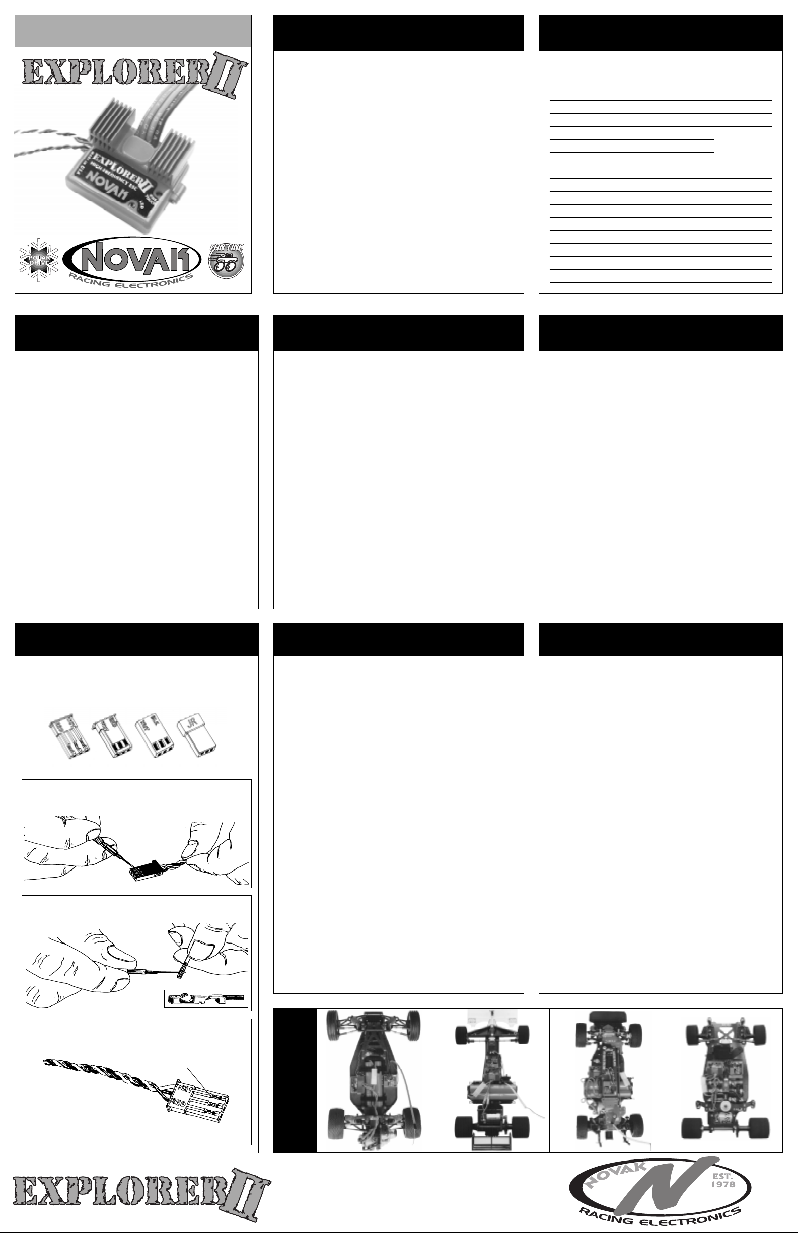
EXAMPLES
INSTALLATION
NOVAK ELECTRONICS, INC.
18910 Teller Avenue
Irvine, CA 92612
www.teamnovak.com
 Loading...