

NorthStar Rim Tach RT8500 Instruction Manual
NorthStar™ brand
Instruction Manual
Manual Number: 791-1060-00 Rev. B
November, 2008
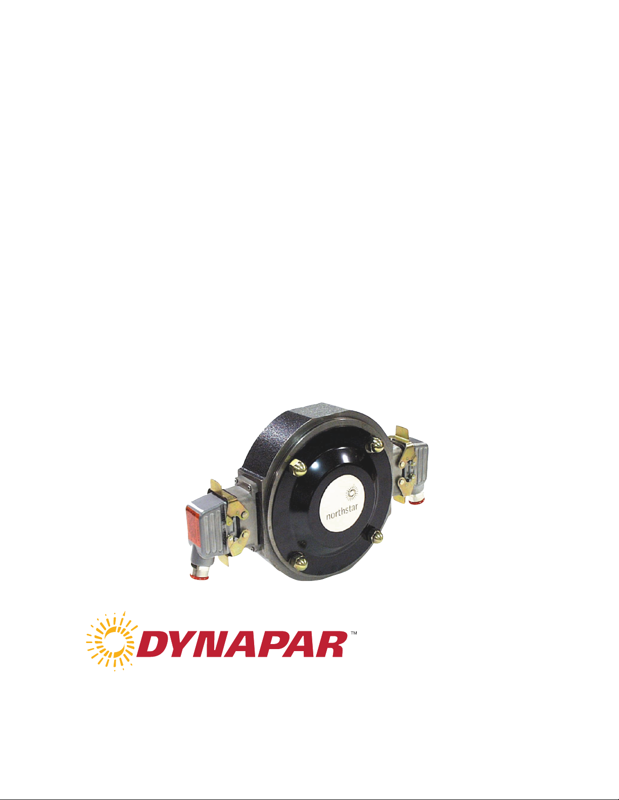
Rim Tach® RT8500
Magnetoresistive Encoder
Designed for use in
with .625” to 4.500” Thru-Shaft Applications and 1.125”,
2.125”, 2.375”, & 2.875” End-of-Shaft Applications

2 ©Dynapar 1-800-873-8731 November 2008

NorthStar RIM Tach® 8500 & 8500 Quad Instruction Manual
Table of Contents and List of Illustrations
Chapter/Paragraph Page
1.0 Introduction ....................................................................................................................................... 4
1.0 Safety Summary........................................................................................................................................... 4
1.1 General ....................................................................................................................... ................................ 5
1.2 Description ..................................................................................................................................................5
Figure 1: RIM Tach
1.3 Specifications ..............................................................................................................................................6
â
8500 Thru-Shaft Enclosure/Sensor Physical Dimensions ................................ 5
2.0 Installation ......................................................................................................................................... 7
2.0 Inspection and Unpacking ........................................................................................................................... 7
2.1 P ainting Considerations ...............................................................................................................................7
2.2 Motor Facing & Shaft ................................................................................................................................. 7
Figure 2 Typical 8.5” Diameter Type C-Face Motor .......................................................................... 8
3.0 Installation Instructions for Pulse Wheels .................................................................................. 8
3.1 Spoked Clamp Style Wheel and Enclosure Installation – 0.625” - 1.250” ID...................................... 9
Figure 3: Enclosure Installation ......................................................................................................10
Figure 4: RimTach 8500 Spoked Wheel Wxploded View 0.625” – 1.250” .................................... 11
Figure 5: Optional Pulse Wheel Alignment Check with Depth Gauge ............................................12
3.2 Ring Clamp Style Wheel and Enclosure Installation 1.375” – 3.25” ID and High Slew Wheel .......... 13
Figure 6: Installation of RimTach 8500 with Clamp Ring Style Wheel ........................................... 13
Figure 7: Alignment for Clamp Ring Style Pulse Wheel ................................................................... 14
3.3 Set Screw Wheel and Enclosure Installation 3.25” – 4.50” ID ............................................................ 15
Figure 8: Pulse Wheel Alignment Check Using Straight Edge ........................................................16
Figure 9: Enclosure Installation .......................................................................................................17
3.4 End of Shaft Wheel and Enclosure Installation ................................................................................... 17
Figure 12: Pulse Wheel Assembly..................................................................................................... 18
Figure 13: Non-Standard End-of-Shaft Mounting............................................................................ 19
4.0 Sensor Module Installation ........................................................................................................... 19
Figure 14: Sensor Module...................................................................................................................20
Figure 15: Sensor Module(s) Installation
.................................................................................... 20
5.0 Electrical Installation .................................................................................................................... 21
Table 1. Signal Coding Table .............................................................................................................. 21
Figure 16: Quick Release Connector Installation................................................................................22
6.0 Returning Equipment to Dynapar ................................. ............................................................ 23
Methods and apparatus disclosed and described herein have been developed solely o n company funds ofDynapar. No govern ment or
other contractual support or relationship whatsoever has existed which in any way affects or mitigates proprietary rights of Dynapar in
these developments. Methods and apparatus disclosed herein may be subject to U.S. Patents existing or applied for.Dynapar reserves
the right to add, im prove, m odify, or w ithdraw functions, de sign modifications, or products at any time without notice. Dynapar s hall n ot be li able for
errors contained herein or for incidental or consequential damages in connection with furnishing, performance, or use of this material.
CHAPTER 1
3 November 2008

NorthStar RIM Tach® 8500 & 8500 Quad Instruction Manual
INTRODUCTION
1.0 Safety Summary
High current, voltage, and rotating parts can cause serious or fatal injury. The use of electric machinery, like all other uses of
concentrated power and ro tating eq uipment, m ay b e h azardous. In stalling, o perating, an d m aintaining electric m achinery
should be perf ormed by qu alified pers onnel, in accordance w ith applicable provisions of the National Electrical Code and
sound local practices . Failure to com ply with these precautions or w ith specific warnings els ewhere in this manual violates
safety standards of design, manufacture, and intended use of the instrument. ©Dynapar assumes no liability
for the customer's failure to comply with these requirements.
Rotating Machinery
Avoid contact with rotating parts. Avoid by-passing or rendering inoperative any safety guards or prot ection devices. Avoid
extended exposure in close proximity to machinery with high noise levels. Use proper care and procedures in handling, lifting,
installing, operating and maintaining the equipment.
Before Installation
Safe maintenance practices with qualified personnel is im perative. Before starting maintenance procedures, be positive that,
(1) equipment connected to the shaft will not cause mechanical rotation, (2) main machine windings have been disconnected
and s ecured f rom all electrical pow er s ources, an d (3) all acces sory dev ices as sociates w ith th e w ork area have been deenergized. If high potential insulation test is required, follow procedures and precautions outlined in NEMA standards MG-1.
Grounding
Improperly grounding the frame of th e m achine can cau se s erious or f atal in jury to pers onnel. Grou nding of th e m achine
frame and structure should comply with the National Electrical C ode and with sound local practices . Check wiring diagram
before connecting power.
Do Not Operate In An Explosive Atmosphere
Do not operate th e instrument in th e presence of f lammable gases or f umes. Operatin g any electrical instrument in such an
environment constitutes a definite safety hazard.
Keep Away From Live Circuits
Operating personnel must not remove instrument covers. Component replacement and internal adjustments must be made by
qualified maintenance personnel. Do n ot replace com ponents w ith pow er cable con nected. T o av oid in juries, alw ays
disconnect power and discharge circuits before touching them.
Do Not Substitute Parts Or Modify Instrument
Do not ins tall substitute pa rts or pe rform a ny unauthorized modification to the instrument. Introducing additional hazards is dangerous.
Return the instrument to an authorized Dynapar representative for service and repair to ensure that safety features are
maintained.
CAUTION!: Crucial information, that must be read and followed regarding safety and unit functioning.
DO THIS!: Additional procedure, that must be read and followed, without safety issues.
NOTE: Useful information that should be read.
QUESTION: Helpful hints to answer your possible questions.
4 November 2008

NorthStar RIM Tach® 8500 & 8500 Quad Instruction Manual
1.1 General
These instructions do not claim to cover all details o f v ariation in eq uipment o r to p rovide f or ev ery p ossible
contingency or hazard to be met in connection with installation, operation, and service. Should further information be
desired or s hould particu lar problems aris e which are n ot covered sufficiently f or the purchaser’s pu rposes, please
contact Dynapar, or one of its designated representatives.
1.2 Description
The RIM Tach
provide position and v elocity f eedback f rom b oth A C an d DC electric m otors w ith p ulse co unts ran ging f rom 6 0
through 1200 pulses per revolution.
Designed for NEMA 180 through 500 diameter AC or DC motor frames, the RIM Tach
iron casting construction, and provides interchangeable sensor modules and a m agneto-resistive technology capable
of withstanding th e h arshest in dustrial en vironments. T his en sures a precis e an d con sistent dig ital m otor s peed
feedback.
The NorthStar R IM Tach
one piece, magneto-resistance sensor module with en capsulated s urface m ount electron ics. T he en capsulation
provides res istance to w ater, oil m ist, dirt, h igh tem peratures, an d oth er h arsh en vironments. The sensor module
includes a 10- pin qu ick con nector requ iring on ly a s crewdriver f or f inal electrical in stallation. T he n on-contact
magneto-resistive se nsor a nd r ugged m agnetized p ulse w heel a re d esigned and machined to function properly
without any adjustments when assembled to a NEMA 180 ty pe C F ace (8.5- inch diam eter) m otor f rame an d
accessory m ount. T here are n o bearin gs to f ail or requ irements f or flexible cou plings s ince th e m agnetized pu lse
wheel as sembly is attach ed directly to th e s haft. T he R IM T ach
many monitoring and control applications, and is a standard feedback device for AC and DC variable speed drives.
The unit is bi-directional providing square wave outputs.
®
8500 (and henceforth 8500 Quad) is a high performance, reliable Digital Tachometer, designed to
The RIM Tach
up to 4.
3.15[80.0]
2.56[65.0]
.20[5.1]
]
]
8
3
3
1
0
0
.
.
[
[
5
5
0
1
0
0
0
0
.
.
+
+
]
9
.
5
1
2
[
0
0
5
.
8
∅
8500 allow s up to 2 s ensor modules, whereas the Rim Tach 8500 Q uad allows
8500 utilizes rugged ductile
®
8500 is mounted directly to th e motor frame and utilizes a patent pending, heavy-duty,
8500 prov ides preci se, rel iable s peed s ignals for
"B"
"D"
]
8
2
2
[
8
9
.
8
.25[64]
(92[234])
4 X 50-13UNC X 3.47 studs
4 X .50-13UNC a corn nuts
on
]
]
5
0
0
.
0
[
[
2
0
0
0
0
0
.
-
]
9
.
)
5
]
1
8
2
5
[
[
0
7
0
2
5
.
.
2
8
(
∅
C
.06[1.5]
(1.02[25])
Figure 1: RIM Tach
1/2" NPT
Conduit Connection
PPR
60, 120, 240, 480, 960
64, 128, 256, 512, 1024-Z
75, 150, 300, 600, 1200-Z
8500 Thru-Shaft Enclosure/Sensor Physical Dimension
"C"
Dim ensio ns (R EF ): inch (mm)
Channels
12.13[308.1]
12.28[312.0]
12.69[322.5]
"C"
Single
B
C
7.33[186.2]
7.48[190.0]
7.89[200.5]
Dual
DC
15.42[391.8]
15.72[399.3]
16.55[420.4]
7.33[186.2]
7.48[190.0]
7.48[190.0]
5 November 2008

NorthStar RIM Tach® 8500 & 8500 Quad Instruction Manual
1.3 Specifications
Electrical Specifications
Frequency Response 0 - 120 kHz
Pulse Code A, B, Z (Index), and complements (A, B, Z)
Output Phases
Pulse Duty Cycle
Quadrature Accuracy
Output Type High speed, differential driver
Rise and Fall Time
Current Consumption 45 mA typical plus line driver load
Output Current 150 mA maximum continuous
ESD Protection 2kV
Maximum Operational Speed 7,000 RPM or 120 kHz
Nominal Air Gap
Shaft Axial End Play
Enclosure Configuration 8.5-inch diameter 180 C motor face or accessory flange to meet NEMA MG1-4 standards
Slew Rate 3,600 RPM/second12,000 RPM (with optional high slew rate pulse wheel)
Enclosure Material Ductile iron casting
Sensor Module Stainless Steel
Approximate Weight 25lb.
Dimensions 22” X 12” X 9”
Operational Temperature
Operational Humidity Range Minimum of 90%
Chemical Resistance Salt spray, most solvents, mild acids and bases
Vibration Minimum 18 g’s RMS, 5-2000 Hz shock spectrum
Shock (Sensor Module) 1 meter drop tested, min. 30g’s
Power +5.0 to +15.0 VDC
Output Differential output swinging between Vcc - 0.6V and Ground
Connector 10 pin industrial latching connector with ½ inch NPT fitting, IP-65 NEMA 4, 12 rated
Suggested Cable 22 - 16 AWG, 10 conductor, shielded, twisted pair
A, B phase @quadrature: 90° phase, Z phase: One per rev. (gated)
50% ± 15% (within defined mechanical specifications)
90° ± 22° (within defined mechanical specifications)
Less than 1µs @ 10,000 pf typical load
Mechanical Specifications
0.019 ± 0.008”
Up to ± 0.050”
Environmental Specifications
-40° to +80° C
Interface Specifications
Specifications subject to change without notice.
CHAPTER 2
INSTALLATION
6 November 2008

NorthStar RIM Tach® 8500 & 8500 Quad Instruction Manual
2.0 Inspection and Unpacking
Inspect shipping container for external damage. A ll claim s for damage (apparen t or con cealed) or partial los s of shipment
must be made in writing to Dynapar within (5) days from receipt of goods. If damage or loss is apparent, please notify the
shipping agent immediately.
Open shipping container and locate the packing list. T he packing list is included to verify that all components, accessories,
and manual were received. Please use the packing list to check off each item as the unit is unpacked. In spect for damage.
Dynapar recommends that the shipping container be retained for future shipping, storage, or return to factory purposes.
If an y equ ipment w as dam aged in tran sit, be s ure to f ile proper claim s prom ptly w ith th e carrier an d in surance company.
Please adv ise Dynapar of such filing. In cas e of parts shortages, advise Dynapar immediately. Dynapar
cannot be responsible for any missing parts unless notified within 60 days of shipment.
2.1 Painting Considerations
The enclosure may be painted. Please pay attention to the following considerations.
• Do not hinder the latches on the connector if the connector is painted.
• If the enclosure is painted before the sensor module(s) is added, be sure to mask off the area where the sensor module(s)
will be placed. The module must mate directly to the enclosure. Failure to do this will degrade the alignment of the
system and may cause it to fail.
• Ensure excess paint runoff does not clog Enclosure drain holes.
2.2 Motor Facing and Shaft
The RIM Tach
MG1-4 Standards. To prepare the motor facing and shaft for installation, perform the following steps.
Clean outer rim and surface of motor facing and shaft of paint, grease, dirt and other debris where RIM Tach
contacts motor or accessory. Also ensure that mating surfaces have not been damaged and that unit will fit squarely on
motor.
®
8500 has been designed to be mounted on a 8.5 inch diameter 180 C Flange that meets or exceeds the NEMA
®
8500 unit
Ensure there is no paint, burrs, protrusions, or deformations on the motor facing or shaft. If the enclosure does not
fit squarely on the motor facing, the alignment between the sensor module and the magnetic pulse wheel may be
degraded.
Apply a thin layer of corrosion preventative or oil to motor facing and shaft to aid assembly and provide some corrosion
protection.
Ensure motor facing and shaft are free from
paint, burrs, protrusions, and deformations
7 November 2008

NorthStar RIM Tach® 8500 & 8500 Quad Instruction Manual
(4) ½” - 13 UNC
1.00” max. engagement
Shaft
Min Shaft
length > 2.49”
8.5” Dia.
(+0.000 to -0.003)
0.24”
Drawing Not
to Scale
Accessory
Mounting
Face
Front View Side View
Figure 2 : Typical 8.5” Diameter Type C-Face Motor
3.0 VERIFY THE TYPE OF WHEEL YOUR APPLICATION WILL
USE. EACH STYLE OF WHEEL HAS IT’S OWN INSTALLTION
METHOD TO ENSURE PROPER ALIGNMENT WITH THE SENSOR.
3.1 Thru Shaft - Spoked/Clamp Style Wheel – 0.675” – 1.25” ID
3.2 Thru Shaft - Ring Clamp Style Wheel – 1.375” – 3.250” ID
and High Slew Pulse Wheels
3.3 Thru – Shaft Set Screw Style Wheel – 3.256” – 4.50” ID
3.4 End of Shaft Style Wheel – 1.125”, 2.125” 2.375” & 2.875” ID of Shaft
8 November 2008
 Loading...