

Page 1
R2D 2
NSTALLATION
I
Part No. GMRad2KIM
Northstar
a unit of Brunswick New Technologies Marine Electronics
30 Sudbury Road
Acton, Massachusetts 01720
K
W
Rev. A
RADAR
ANUAL
M
www.NorthstarNav.com
Service: 978/897-6600
Sales: 800/628-4487
Page 2

Page 3

Contents
SECTION ONE: Introducing the Northstar radar
SECTION TWO: Installing and wiring the radar
Installing the antenna
Wiring the radar
SECTION THREE: Setting up the radar
Configuring the navigator
Calibrating the radar
Adjusting the appearance settings
Finishing up
- - - - - - - - - - - - - - - - - - - - - - - - - - - - - - - - - - - - - - - - - - - - - - - - - 18
- - - - - - - - - - - - - - - - - - - - - - - - - - - - - - - - - - - - - - - - - - 4
- - - - - - - - - - - - - - - - - - - - - - - - - - - - - - - - - - - - - - - - - - - - - - - 7
- - - - - - - - - - - - - - - - - - - - - - - - - - - 13
- - - - - - - - - - - - - - - - - - - - - - - - - - - - - - - - - - - - - - 13
- - - - - - - - - - - - - - - - - - - - - - - - - - - - - - - - - - - - - - - - - - 15
- - - - - - - - - - - - - - - - - - - - - - - - - - - - - - - - 18
SECTION FIVE: Using manual control functions
Gain and clutter adjustments
Other functions
- - - - - - - - - - - - - - - - - - - - - - - - - - - - - - - - - - - - - - - - - - - - - - 23
SECTION SIX: Servicing the radar
- - - - - - - - - - - - - - - - - - - - - - - - - - - - - - - - - - - 21
- - - - - - - - - - - - - - - - - - - - - - - - - - - - - - - 25
- - - - - - - - - - - - - - - - - - - 1
- - - - - - - - - - - - - - - - - - - - 3
- - - - - - - - - - - - - - - - - - - 21
Contacting Northstar
Hearing from you
Using the Dealer Express web pages
Returning a radar for service
- - - - - - - - - - - - - - - - - - - - - - - - - - - - - - - - - - - - - - - - - - 25
- - - - - - - - - - - - - - - - - - - - - - - - - - - - - - - - - - - - - - - - - - - - - 26
- - - - - - - - - - - - - - - - - - - - - - - - - - - - - - 26
- - - - - - - - - - - - - - - - - - - - - - - - - - - - - - - - - - - - 26
APPENDIX A: Specifications and Drawings
APPENDIX B: Manual Tuning Procedure
- - - - - - - - - - - - - - - - - - - - - - - - - 29
- - - - - - - - - - - - - - - - - - - - - - - 27
Page 4

Page 5
SECTION ONE: Introducing the Northstar radar
WARNING!
WARNING!
Microwave Radiation Hazard
The microwave energy radiated by a radar antenna is
harmful to humans, especially to one’s eyes. Never look
directly into an open waveguide or into the path of
radiation from an enclosed antenna. Radar and other
radio frequency radiation can upset cardiac
pacemakers. If someone with a cardiac pacemaker
suspects abnormal operation, immediately turn off the
equipment and move the person away from the
antenna. Turn off the radar whenever it is necessary to
work on the antenna unit or on other equipment in the
beam of the radar.
High Voltage Warning
Dangerously high voltages are present within the radar
scanner unit. There are no internal connections or
adjustments necessary for installation. The cover
should be removed only by a qualified radar service
technician. Technicians must exercise extreme care
when working inside the unit. Always remove power
before removing the cover. Some capacitors may take
several minutes to discharge, even after switching off
the radar. Before touching the magnetron or any high
voltage components, ground them with a clip lead.
The Northstar R2D radar is designed as an option available for the Northstar 6000i navigator.
A radar unit should only be installed by a qualified marine technician, as potentially lethal high
voltage is present, along with heavy rotating parts. There is a transmit interlock that prevents radar
transmissions if the array is not rotating. However, high voltage remains for a period of time after the
system is turned off. If you are not familiar with this type of electronics, consult with a trained
service or installation technician before attempting to service any part of the equipment.
Installation includes mechanical mounting and electrical wiring, followed by properly configuring
the navigator to work with the radar, and finally adjusting the radar for proper performance.
Don’t take any shortcuts, and follow these instructions carefully.
R2D Radar Installation Manual, Rev. A Page 1
Page 6
SECTION ONE: Introducing the Northstar radar
NOTE:
For the radar overlay to function properly on the chart screen, you must
correctly
navigator’s NMEA interface connector, pins 1 and 3). Without the heading
sensor, the radar image will not line up properly with the chart.
The Northstar 6000i accepts the following standard NMEA 0183 sentences
to obtain heading information from a sensor: HDG, HDT, OSD, HCC, HCD,
and HDM.
For sensor installation and calibration instructions, see the sensor
manufacturer’s installation manual. In addition, the navigator must be
calibrated to the heading sensor as described on page 17
install and calibrate a separate heading sensor (using the
Components supplied are listed on the next page.
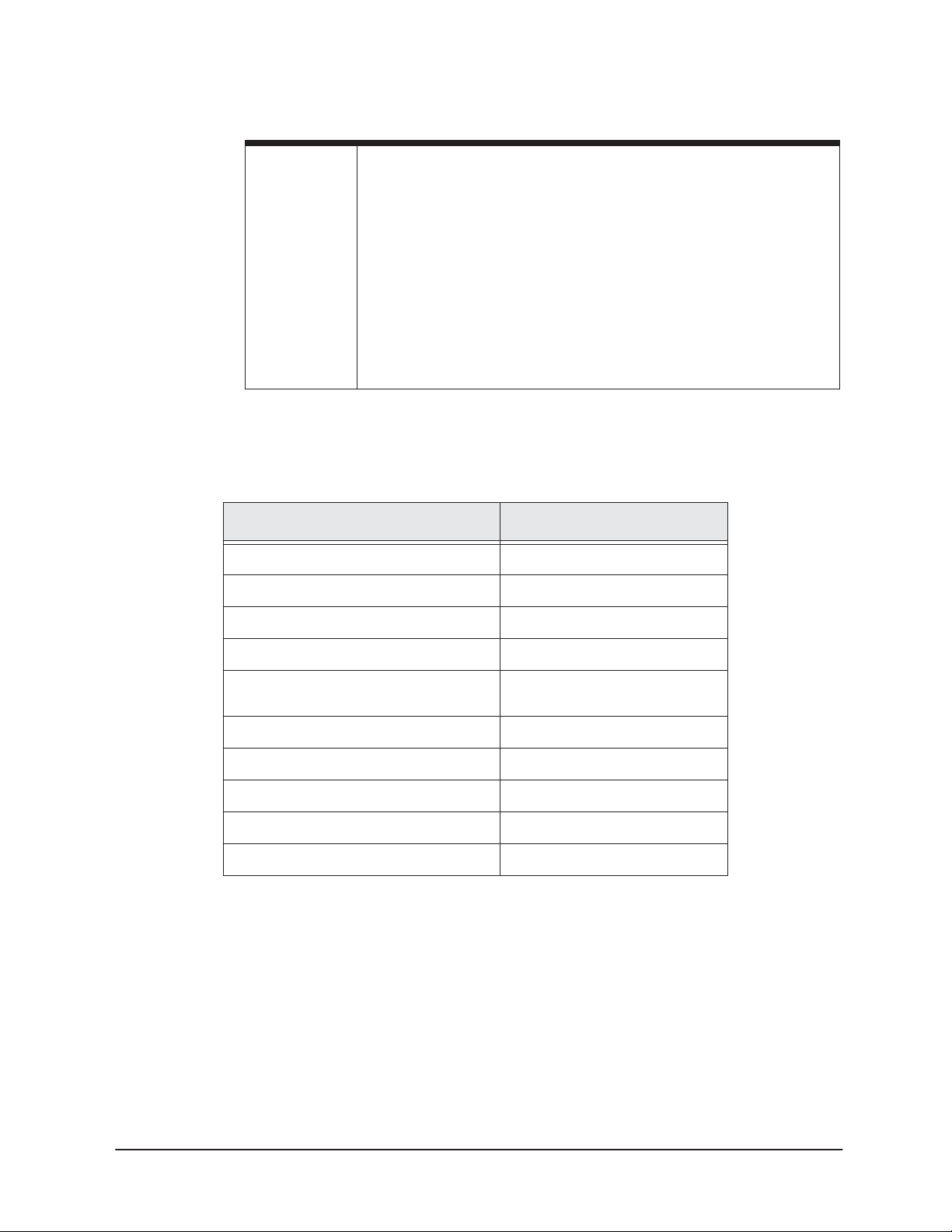
TABLE 1: Radar parts list
Description
Radome R2D
Installation Manual GMRAD2KIM
Part Number
Mounting Template GTR2DOME
Power Switch ST165
Cable, 10 meters (5m, 15m, 20m
optional)
Cable navigator I/O WA215SR-C
(4) Mounting bolts, metric, M10 X 25U
(4) Flat washers
(4) Lock washers
(2) Fuses, 5A (spare)
WC274
Page 2 R2D Radar Installation Manual, Rev. A
Page 7
SECTION TWO: Installing and wiring the radar
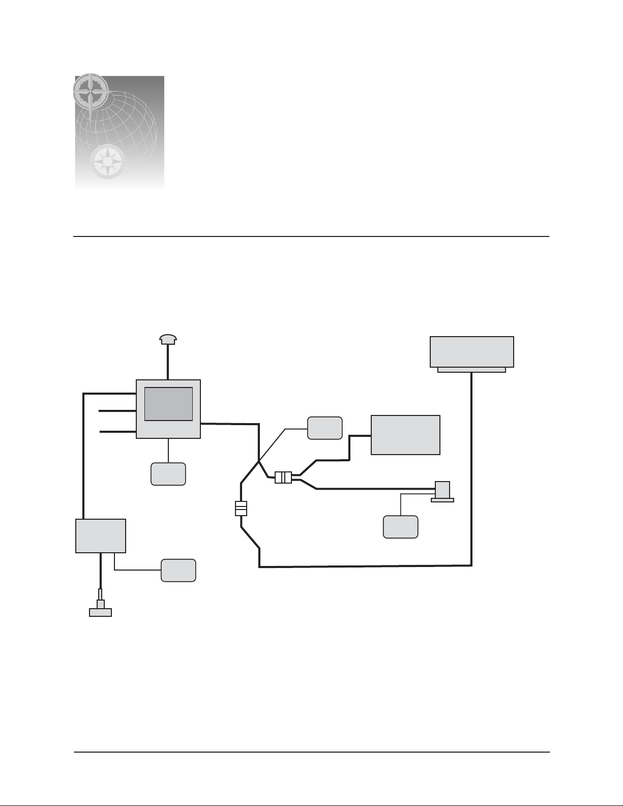
System diagram
A configuration diagram for a fully-optioned Northstar system with radar, heading sensor and
echosounder is shown in Figure 1. This diagram provides an overview of the interconnection
between components.
2301, AN150 or AN156
GPS/WASS
Antenna
Prefabricated
Antenna Cable
Northstar
2kW Dome Radar
Aux Port
VGA out
NTSC in
Northstar
Echo
Sounder
Northstar
Navigator
Ship's
power
Transducer
NMEA Port 2
Ship's
power
WA215SR-C
I/O cable
In and Out
Ship's
power
NMEA Port 1 out
NMEA Port 1 in
5, 10, 15 or 20m
NMEA device
repeater, etc.)
WC274
cable
(Autopilot,
Heading
Ship's
power
sensor
Figure 1: System diagram
R2D Radar Installation Manual, Rev. A Page 3
Page 8

SECTION TWO: Installing and wiring the radar
Installing the antenna
Do
Do
Do
Do
Do
CAUTION!
To eliminate interference, install the antenna away from GPS and radio
receiver antennas, including SatNav and satellite TV antennas.
Choosing the antenna location
The radar’s ability to detect targets depends greatly on the position of its antenna. The ideal antenna
location is high above the ship's keel line where there aren’t any obstacles. This ideal location is
limited by various factors; therefore, consider the following when choosing the antenna location:
•
install the antenna as high as possible (after considering the structure of the vessel’s
hull, the weight of the antenna, and how easy it will be to maintain the antenna). The
higher the installation position, the longer the radar ranging distance.
•
install the antenna away from masts or other obstructions. If the antenna isn’t higher
than obstructions, radar waves may be blocked, creating shadow zones or generating false
echoes.
•
install the antenna closer to the vessel’s bow, for a clear view to the front. When
installing the antenna on a mast, place it in front of the mast. If obstacles can’t be avoided
for vessel structural reasons, see “Shifting the antenna away from the keel line,” described
below.
•
install the antenna as far away as possible from the antennas of other equipment, such
as direction finders, GPS equipment, radio receivers, etc. Radar scanners may cause
interference with radio receivers.
•
keep the connecting cable as short as possible. Whenever possible, keep the distance
from the antenna to the navigator within the standard cable length of 10 meters. If you
must use longer cable, do not exceed 30 meters.
•
Don’t install the antenna where it may be subjected to smoke or hot air from smokestacks
or heat from lamps.
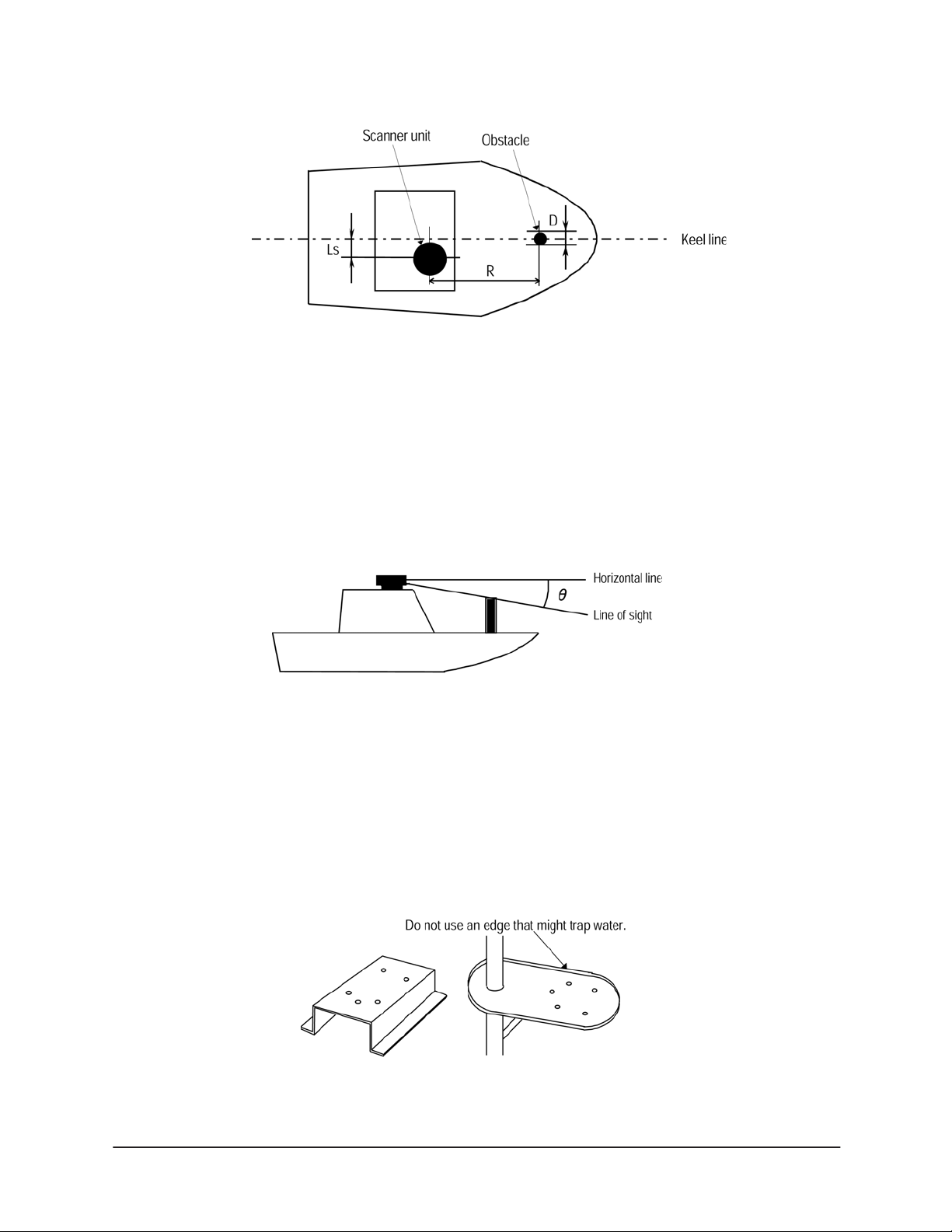
Shifting the antenna away from the keel line
By shifting the antenna position from the keel line to starboard, it’s possible to move shadow zones
to the port side. This makes it possible to keep a clear view to the bow. You can calculate the distance
to be shifted, depending on the distance from the antenna to any obstacles, by using the following
equation (Ls = distance to be shifted from keel line; D = diameter of obstacle on keel line; and R =
distance from antenna to obstacle):
Ls=0.4R+D/2 (when R<15m)
Ls=0.025R+D/2 (when R>=15m)
Page 4 R2D Radar Installation Manual, Rev. A
Page 9
SECTION TWO: Installing and wiring the radar
Figure 2: Shifting from the keel
Obtaining sufficient dip angle
Raise the antenna position above on-board obstacles to avoid shadow zones. Dip angle is the angle
between a horizontal line and the line of sight from the antenna to the obstacle. By maintaining a dip
angle greater than 5 degrees, you may be able to prevent mid- and long-distance shadow zones. The
radar can’t detect objects below its line of sight.
Figure 3: Sufficient dip angle
Mounting the antenna
It may be easier to install the antenna by fabricating a mounting base, as shown below, but you can
also install the antenna directly to a rigid, flat surface, such as the roof. Pay attention to the water
drain tube at the bottom of the antenna.
Figure 4: Using a mounting base
R2D Radar Installation Manual, Rev. A Page 5
Page 10
SECTION TWO: Installing and wiring the radar
NOTE:
When the radar platform or mounting bracket has a curvature of more than
2mm, repair it or use spacers.
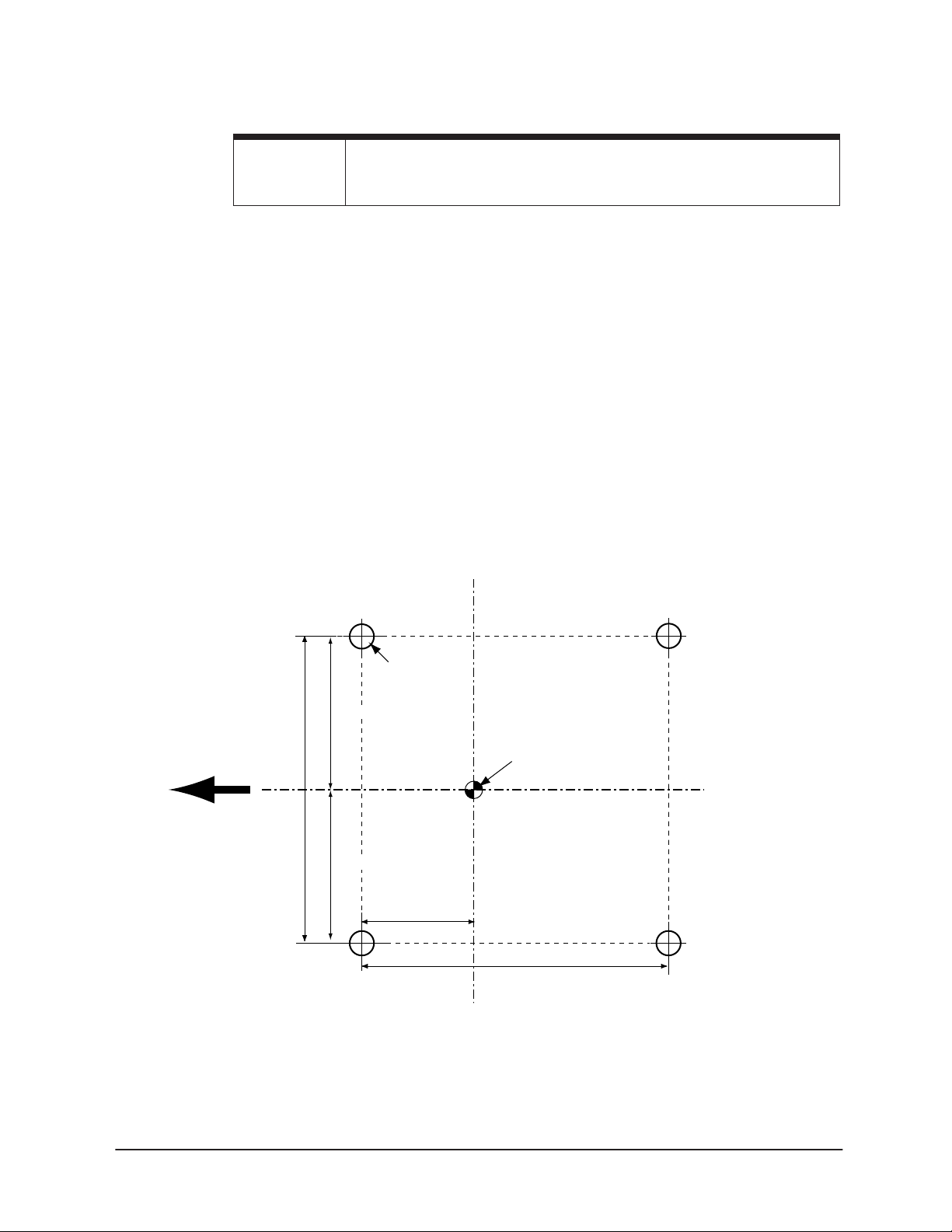
1. Referring to Figure 5 below and the supplied full-size antenna mounting templates, drill four
1/2 in. (13mm) diameter holes through the mounting surface.
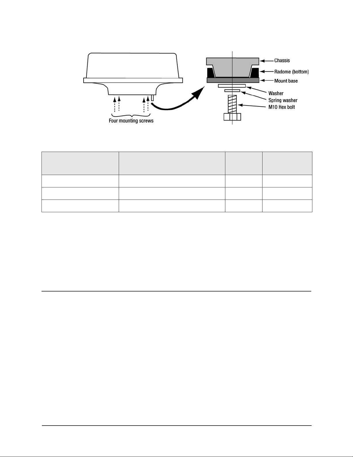
2. Check that each bolt (with lock washer and flat washer) protrudes at least 5/15 in. (8mm) but
less than 9/16 in. (15mm). The scanner will be damaged if bolts protrude more than 9/16 in.
(15 mm).
3. Apply sealant around each mounting hole.
4. Place the radome scanner unit on the mounting surface. Orient the radome with the index
mark on the housing facing forward (cable gland facing aft).
5. Install and tighten four M10 X 25U (M10 X 1 in.) mounting bolts
6. Secure the cable near the scanner to support the weight of the cable and prevent strain on
the watertight cable seal.
The bolts supplied will suffice for mounting base thicknesses of 3/16 to 3/8 inch (5 to 10 mm). If the
mounting base is thicker or thinner than that, use bolts specified in Table 2 on page 7. See Figure 6
below for details on bolting the antenna to the mounting base.
Ship's Heading
5-7/8 (148.5)
2-15/16 (74.24)
2-15/16 (74.25)
1/2 (13) dia.
Mounting Holes
4 places
2-9/16 (65)
Dimensions in inches (mm)
Center of radome
5-7/8 (148.5)
Figure 5: Hole positions for mounting radome
Page 6 R2D Radar Installation Manual, Rev. A
Page 11
SECTION TWO: Installing and wiring the radar
Figure 6: Mounting the radome antenna
TABLE 2: Bolts for mounting radome antenna
Do
Do
Do
Thickness of
mounting base
3/16 – 3/8 in. (5 – 10mm) M10
7/16 – 9/16 in. (11 – 15mm) M10
5/8 – 3/4 in. (16 – 20m) M10
Radome mounting bolts Material Comments
×
25 (1.5mm pitch) Stainless Included
×
30 (1.5mm pitch) Stainless
×
35 (1.5mm pitch) Stainless
Replacing the fuse
You must use proper rating fuses to safely operate the radar. Replace the internal fuse with a 5A
125V fuse only.
Wiring the radar
Regardless of the type of antenna, when connecting the cables, keep in mind the following:
•
Do not tie the radar cables, especially the power supply cable, together with the cables of
other equipment
•
leave service and drip loops so you can easily remove the control box
•
mount the control box in a dry area protected from moisture and humidity
•
lay the cable along the vessel’s hull or wall surface, and secure it at intervals of about
16” (40 centimeters)
Install the radar antenna cable as described below.
R2D Radar Installation Manual, Rev. A Page 7
Page 12

–
SECTION TWO: Installing and wiring the radar
Pre-wired cables
The supplied WA215SR-C cable plugs into the navigator’s 18-pin connector, and connects to the
radar, radar power source, radar power control, and NMEA accessories.
Power control
Blue
Green
+V Red
V Black
Connect to
navigator
Connect to
heading sensor
and NMEA Port 1 device
(Autopilot) using WA598
connector (not supplied)
WA215SR-C
WA215SR-C cable — navigator to power source point
N/C
Connect to
WC274 cable
To coil of
optional
power control
relay
Figure 7: Pre-wired WA215SR-C cable
The WC274 cable connects between the WA215SR cable and the radar dome.
Connect
to WA215SR
cable
WC274
WC274 cable — radar to navigator cable
from
radar
dome
Figure 8: Pre-wired WC274 cable
Radome cable connection
Use the following instructions along with Figure 1 for connecting to cable to an enclosed radome.
1. Connect the WC274 cable between the navigator and the WA215SR radome cable.
2. Connect the supplied WA215SR-C cable to the navigator’s NMEA port and run the other end
to the interconnection point.
3. To connect a heading sensor and/or other device to NMEA Port 1, use an optional WA589
connector as shown in Figure 7
Page 8 R2D Radar Installation Manual, Rev. A
Page 13

Connecting the power wiring
The R2D unit is designed for 12/24/32-volt installations.
SECTION TWO: Installing and wiring the radar
CAUTION!
Power should be fed through a switch and protective fuses (or circuit breakers).
To connect the power cable:
1. Connect the red wire from the WC274 cable to V+ (12 to 32 VDC).
2. Connect the black wire from the WC274 cable to V–.
Do not apply over 41.6V to the radar or it may be damaged.
Radar power control
Electrical power for the radar’s standby state is controlled by the blue and green wires in the WC274
cable. When these wires are connected to each other, the radar powers up and enters standby mode.
When they are not connected, the radar is turned off (although it still draws a tiny amount of power).
Connect the blue and green wires in any one of the following three ways:
•
Option 1: Connect the blue and green wires to an S.P.S.T. switch as shown in Figure 9 to
control the radar’s power An appropriate switch is included with the radar.
Figure 9: Using a switch to control radar power
•
Option 2: Permanently connect the blue and green wires to each other, and control the
radar’s power from a switched circuit breaker at the mains circuit panel.
•
Option 3: Connect the blue and green wires to a set of relay contacts controlled by the
navigator, so that the radar will turn on to standby mode automatically whenever the
navigator is turned on. Control the relay using the pink wire (“Honk” output) from the
WA215SR cable, and install a spike-suppression diode across the relay coil as shown in
Figure 10.
R2D Radar Installation Manual, Rev. A Page 9
Page 14

SECTION TWO: Installing and wiring the radar
r
An appropriate relay for Option 3 (with a 12-volt coil, and complete with
instructions) is available from Northstar as part number RELAY-IK. An appropriate
relay can also be obtained from Greenwich Electronics (www.geirelays.com, or
888-554-5561) using P/N HD1-012D-A30PMS for a 12-volt system, or
HD1-024D-A30PMS for a 24-volt system. Using this relay, the coil is connected to
the narrow tabs and the contacts are connected to the wide tabs (labelled COM and
NO).
Note: Choose a relay that’s compatible with the ship’s power
Figure 10: Using a relay to control radar powe
If the relay is used for power control, the navigator’s Honk output must be configured for power
control as follows:
1. Press the STAR key to display the alarms page.
2. Press the Cursor Pad down to highlight “Honk Output.”
3. Press Edit, press the Cursor Pad up or down to display REMOTE PWR.
4. Press ENTER.
The 200ppnm or alarm outputs can not be used when this output is used for power
control.
Page 10 R2D Radar Installation Manual, Rev. A
Page 15

SECTION TWO: Installing and wiring the radar
Wiring heading sensors
The WA215SR cable is pre-wired with a connector for interfacing to various heading sensors. Other
sensors can be connected as shown in the following tables.
ROBERTSON RFC35N HEADING
NORTHSTAR NMEA 18-PIN CONNECTOR
SENSOR
Wire Color Description Pin No. Wire Color Description
Brown Tx– Data Ground 1 Blue NMEA Port 1 in B
White Tx + Data Transmit 3 Brown NMEA Port 1 In A
Green Rx– Data Ground Not Connected
Yellow Rx+ Data Receive Not Connected
Pink Vin+ Power A+ Ship’s Power Supply, Fused, 12 VDC
Gray Vin– Power Ground Ship’s Power Ground
KVH AUTOCOMP 1000 HEADING
NORTHSTAR NMEA 18-PIN CONNECTOR
SENSOR (P/N 01-0118-0001)
Wire Color Description Pin No. Wire Color Description
Orange NMEA 0183 Out – 1 Blue NMEA Port 1 in B
Green NMEA 0183 Out + 3 Brown NMEA Port 1 In A
White Damping 0 Connect to Power Ground
Brown Damping 1 Connect to Power Ground
Blue AutoComp Disable Do not connect. Cap and Insulate
Red 12 VDC Power Ship’s Power Supply, Fused, 12 VDC
Black Power Ground Ship’s Power Ground
Drain, Foil,
Shield
R2D Radar Installation Manual, Rev. A Page 11
not used Not Connected
Page 16

SECTION TWO: Installing and wiring the radar
Page 12 R2D Radar Installation Manual, Rev. A
Page 17

SECTION THREE: Setting up the radar
Note: It is important that the navigator’s Demo Mode
Several menu keys need to be activated before the adjustment they control can be changed. Here’s
how they work:
• any key displayed in red is active and can be adjusted by pressing it or (in many cases) by
using the keypad or cursor pad to change its value
• any key displayed in blue is inactive and must be pressed once to activate it before
changing its value.
The radar normally provides a good picture when used in its automatic modes, described below.
In many cases, the picture can be improved by using the Range Rider mode, also described below.
not
be used while a radar unit is connected.
Configuring the navigator
To enable an installed radar to communicate with the navigator, you must first set up the radar
option on the navigator’s PORT 2 SETUP screen:
1. Press the STAR key several times to display the OPTIONS/SERVICE INFO screen.
2. Press
3. Press
4. Press Edit, and press the Cursor Pad up or down to select Radar.
5. Press
Port Setup Options.
Port 2 Setup, and use the Cursor Pad to select the Output Format line.
Enter.
You do not have to re-start the navigator for this option to take effect.
Configuring the radar as described also configures the heading sensor wired to NMEA Port 1.
IMPORTANT: If the system will be operated without a heading sensor,
it is absolutely necessary to change this configuration
as described in “Heading sensor requirements” on
page 14.
R2D Radar Installation Manual, Rev. A Page 13
Page 18

SECTION THREE: Setting up the radar
Radar transmitter power
As a safeguard against antenna rotation and radiation, the radar transmitter must be turned on
manually each time the navigator is turned on, as described below. Be sure no injury will be caused
when the antenna starts rotating.
CAUTION: Be sure to turn the transmitter off using the same proce-
dure, or by removing radar power, before servicing the
unit or working in the vicinity of the rotating antenna.
The radar does not automatically turn off when the
navigator is turned off, unless the power control relay
has been installed.
Heading sensor requirements
For all radar functions to operate properly, a heading sensor should be installed as described on
page 11 and calibrated as described on page 17. The sensor may be a stand-alone unit, or may be
integrated into an autopilot system, provided it outputs the NMEA 0183 HDG, HDT, OSD, HCC,
HCD or HDM heading sentence to the navigator.
If the heading sensor requires sea trial calibration, perform the manufacturer’s recommended
calibration procedure before attempting to perform the radar heading calibration described below.
Heading calibration should be performed during initial setup, annually, and after any major
structural changes that are made to the vessel.
Disabling the heading sensor input
The heading sensor is configured by default when the navigator is configured for radar. If a heading
sensor is not installed and connected, it is absolutely necessary to remove its configuration as
described below.
If a heading sensor is not installed:
1. Turn the navigator on and let it complete its power-up sequence.
2. Display the radar screen:
• On the 958, press CHART, Split, and Radar.
• On the 6000i, press RADAR.
3. The unit will ask if you want to turn on the radar transmitter. Press Enter turn it on.
4. Press Page 2, Page 3, Page 4, and Install... to access the installation screen.
5. Press Hdg Sensor Installed to change its displayed status to No.
6. Clear the heading sensor alarm by pressing the STAR key to display the alarm screen and
press Clear Alarm.
Page 14 R2D Radar Installation Manual, Rev. A
Page 19

SECTION THREE: Setting up the radar
Calibrating the radar
A newly installed radar must be calibrated by adjusting the trigger delay and heading calibration.
Calibration and check-out should be performed in a normal operating environment and under fair
weather conditions. A wave height of approximately one to two feet, causing some sea clutter, is
ideal. The vessel must not be in an enclosed area or in a busy location such as a boat yard. Ideally, an
area of at least 3nm forward of the vessel, containing known targets including the coastline, should
be available for evaluation of close and medium range radar returns. Attempts to tune and calibrate
under less than recommended conditions may lead to substandard performance. A sea trial that
allows the selection and use of all ranges is highly desirable.
The Northstar radar uses a fully automatic tuning procedure that continuously checks for optimum
adjustment during operation. Northstar recommends using auto tuning mode for normal operation.
For special situations requiring manual tuning, see Appendix B.
Preparing for calibration
To prepare for calibration, do the following:
1. Display the radar screen by pressing RADAR.
2. The unit may ask if you want to turn on the radar transmitter. If it does, turn it on.
At this point, you should see range rings
displayed on the screen. You may see the
transmitter warm-up countdown displayed
(updated every five seconds), followed by the
message “Radar is OFF.”
If no messages or range rings appear, then
the radar control box is not powered or is not
properly interfaced to the navigator. Check
power wiring, interface wiring, and
navigator configuration as described above.
3. Press Page 2 and then Page 3, Page 4, and
Restore... .
4. Press Restore factory settings.
A new Northstar 6000i is shipped set up with standard factory settings appropriate for basic
operation.
5. Press Return.
Radar tuning
Tuning makes the radar receiver frequency match the transmitter frequency.
For normal operation of a Northstar radar, setting the tuning mode to Auto is recommended. To tune
the unit manually see Appendix B. To check the tuning mode or change it to
1. From Page 4 (selected above), press
2. If necessary, press
Tune mode repeatedly until it displays Auto.
Install... and Tune... .
Auto:
R2D Radar Installation Manual, Rev. A Page 15
Page 20

SECTION THREE: Setting up the radar
Recalibrate mode
The system is shipped from the factory with its tuning fully calibrated for optimum operation.
northstar strongly advises that this calibration not be changed, unless the transmitter/receiver
module has been replaced, or if the automatic tuning is otherwise badly misadjusted. Tuning can be
recalibrated if necessary by pressing Recalibrate on the tuning screen. This operation is fully
automatic, but it requires up to 15 minutes. Do not change the display while recalibration is in
progress.
Setting the Trigger Delay
There are two methods that can be used to set the Trigger Delay. The two methods should produce
very similar settings. The installer may use either or both methods. Method One is the easier method
to perform; Method Two may produce more accurate results.
The procedure should be performed after the factory settings have been restored as described above,
or by manually turning off the Interference Rejection, Trails and Expand functions.
Method 1:
This method should be used while the vessel is in open water with few or no nearby echoes.
First, we need to set the rain clutter and sea clutter to 0 and the gain to 50.
1. From the main radar screen, press Page 2.
2. Press the zoom IN key several times to zoom in to the most magnified image (1/8 nm).
3. If necessary, press Mode to make it read Manual.
4. Press Rain Cutter to activate the control.
5. Press the “0” key on the keypad to set the rain clutter value to zero.
6. Press Sea Clutter.
7. Press the “0” key on the keypad three times to set the sea clutter to zero.
8. Press Gain to activate the control.
9. Press “1,” “5” and “0” on the keypad to set the gain to 150.
The screen will display a green ring with black center (assuming you are using the standard green
screen colors).
If this gain setting does not display the green ring on the screen, try other gain settings until the
green ring is displayed clearly. Using too high a gain setting may saturate the image.
10. Press Page 3, Page 4, and Install... .
11. Press Trigger Delay. Set the trigger delay to zero by pressing “000” on the keypad.
12. Increase the trigger delay by pressing the Cursor Pad to the right (or enter a larger number
on the keypad). The black circle will shrink as you increase the trigger delay. Set the trigger
delay so that the black center just disappears, with a one or two dots remaining in the very
center of the screen.
Method 2:
The vessel should be located 50 to 100 yards from a straight jetty or other landmark that should
produce a straight-line echo on the screen.
1. Adjust the gain to obtain a reasonably good image of the jetty echo.
Page 16 R2D Radar Installation Manual, Rev. A
Page 21

SECTION THREE: Setting up the radar
2. Adjust the Trigger Delay to make the jetty echo appear as a straight line on the screen as
shown in Figure 11.
Jetty
Vessel
Incorrect Incorrect Correct
Figure 11: Adjusting Trigger Delay
Setting the Heading Calibration
The heading calibration rotates the radar image on the screen to line it up with the displayed chart
and the compass. Accurate heading calibration is especially important when overlaying the radar
image onto the chart.
1. Make sure the heading sensor is calibrated according to the
manufacturer’s instructions.
When sea trialing the vessel, set a straight course for a solid object such as
a lighthouse, jetty, or radar nav marker that is at least 1 nm away as
referenced on the chart.
2. Turn on the radar overlay feature: Press CHART to display the chart and press Overlay to
display radar echoes overlaid on the chart.
3. Set the chart rotation to North-up by pressing Rotate several times until North up is
displayed.
4. Find a target that appears on both the radar image and the chart. An appropriate choice
would be a land pattern or solid object about a mile or more from the vessel, with a fixed
point, such as a jetty, lighthouse, or pier. (Avoid beaches and buoys as these may have radar
images that don’t align with the chart.) Zoom in as necessary to place identifiable objects
near the outer edge of the screen.
5. Press the Control key so that it displays Radar.
6. Press Page 2, Page 3, Page 4, and Install... .
7. Press Heading Calibrate and press the Cursor Pad left and right to rotate the radar image so
that the radar target matches its compass heading on the chart and lines up on top of the
position shown on the chart.
Antenna parking position
Adjusting the antenna parking position is not necessary for a dome antenna.
R2D Radar Installation Manual, Rev. A Page 17
Page 22

SECTION THREE: Setting up the radar
Adjusting the appearance settings
The Mode, Rain Clutter, Sea Clutter and Gain are normally set to automatic mode to obtain an
excellent image under most conditions.
To access these controls, press Page 2 from the main radar screen.
The Mode key determines how the gain and clutter keys work. It has the following settings:
• Auto 1 is for normal, open-water use in calm seas.
• Auto 2 is for normal, open-water in rough seas.
• Harbor automatically optimizes the radar settings for use in a harbor.
• Range Rider is a Northstar exclusive feature recommended when manual settings are
required. The user can freely make any needed gain and clutter adjustments, and these
settings are “remembered” for each range. When the range is selected again, the last-used
gain setting for that range is reapplied.
• Manual is a fully manual function in which the user will usually need to adjust the settings
each time the range is changed.
Any settings made to Rain Clutter, Sea Clutter and Gain in Auto mode are discarded when the unit is
switched away from an Auto mode (unless they have been saved as described in the next section).
Restoring factory settings
Appearance settings and manual settings can be restored to values that normally produce a useful
pictures as follows:
1. From the main radar page, press Page 2, Page 3, Page 4, and Install... .
2. Press Restore... .
Press Restore Auto, Restore Harbor, Restore Range Rider, and/or Restore Manual to set these items
back to their state when the unit was shipped from the factory.
Finishing up
This completes the installation calibration. Note that the heading correction may need to be adjusted
slightly after the gain is optimized to provide a better picture, as described in the next section.
Although the basic installation has been completed, it is best to complete Section 4 to check out and
optimize the entire system.
Restoring all factory settings
If you ever wish to restore all radar settings to their factory settings (except trigger delay, heading
calibration and whether or not a heading sensor is installed), do the following:
1. From the main radar page, press Page 2, Page 3, Page 4, and Install... .
2. Press
Page 18 R2D Radar Installation Manual, Rev. A
Restore... .
Page 23

SECTION THREE: Setting up the radar
3. Press Restore factory settings to return the unit to its state when it was shipped (with the
exception of the following:
• trigger delay
• heading calibration
• whether or not a heading sensor is installed
• parking calibration (for open array antennas)
This function is used before performing manual tuning (see Appendix B), or any time it is necessary
to restore the unit to a known state.
R2D Radar Installation Manual, Rev. A Page 19
Page 24

SECTION THREE: Setting up the radar
Page 20 R2D Radar Installation Manual, Rev. A
Page 25

SECTION FIVE: Using manual control functions
This section contains an overview of the radar’s manual control functions and how to use them. All
radar adjustments take effect immediately — pressing ENT, Done or Return is not necessary.
Some of the functions described in this section are found only in Northstar software version 8.0 and
later, and in Northstar 6000i software version 1.61 and later.
Gain and clutter adjustments
The Mode, Rain Clutter, Sea Clutter and Gain can be set to automatic mode to obtain an excellent
image under most conditions. Some situations may require manual settings.
To access these manual controls, press Page 2 from the main radar screen.
The Mode key has the following settings:
• Auto 1 and Auto 2 are for normal, open-water use.
• Harbor automatically optimizes the radar settings for use in a harbor.
• Range Rider is a Northstar exclusive feature recommended when manual settings are
required. The user can freely make any needed gain and clutter adjustments, and these
settings are “remembered” for each range. When the range is selected again, the last-used
gain and clutter settings for that range are reapplied. In addition, the Sea State control can
apply further adjustments to sea clutter over all ranges as needed for current conditions.
• Manual provides fully manual control, in which the user usually needs to adjust the
settings each time the range is changed.
Automatic settings are described on page 18, “Adjusting the appearance settings.”
Manual settings directly control Rain Clutter, Sea Clutter and Gain. They may be applied in either of
two ways, depending on the setting of the Mode control on this screen.
• Mode = Manual: settings usually need to be adjusted every time the range is changed
• Mode = Range Rider: settings are saved separately for each range, and the last-used
settings for each range (modified by the sea state control) are reapplied when that range is
selected
R2D Radar Installation Manual, Rev. A Page 21
Page 26

SECTION FIVE: Using manual control functions
Rain Clutter
Enter the rain clutter setting on the keypad or by using the cursor pad. Manual settings range from 0
to 8. Higher settings suppress more rain echoes.
Sea Clutter
Enter the sea clutter setting on the keypad or by using the cursor pad. Manual settings range from 0
to 255. Higher settings suppress more sea clutter echoes.
The Sea Clutter control can also be used to lower the gain near the vessel Doing this can help
eliminate side lobe echoes, or to separate two or more close echoes that appear as one large echo on
the screen.
Gain
Enter the gain setting on the keypad or by using the cursor pad. Manual settings range from 0 to
255. Higher settings display more echoes.
Manual gain adjustments will be different for each range scale. Longer ranges generally require more
gain. Using the Range Rider function described above minimizes the need for frequent adjustments.
Other adjustments
Sea state
The Sea State control is only available when the radar’s Mode is set to Range Rider. Sea State adjusts
the sea clutter up or down slightly to correspond with the expected echoes from whitecaps and
breaking waves. The normal or “0” setting applies no changes, and is used when the sea state is the
same as when the settings were entered. Positive numbers are used when the sea is rougher, and
negative numbers when the sea state is calmer.
For safety reasons, the Sea State is automatically set back to “0” each time the unit is turned on.
To set the Sea State (when in Range Rider mode):
1. From the main radar screen, press
2. Press
3. Use the cursor pad to enter a new number. Changes are shown immediately on the screen.
4. Press Done to return to the main radar screen.
Sea State.
Page 2 and Page 3.
Page 22 R2D Radar Installation Manual, Rev. A
Page 27

SECTION FIVE: Using manual control functions
Sweep type
The Northstar radar can be set to display images in either of two ways:
• displaying digital data in quadrants directly as it comes from the radar receiver
• simulating the analog sweep of traditional radars
Choose whichever display is more pleasing to the operator.
To change the sweep type:
1. From the main radar screen, press Page 2, Page 3, Page 4, and Preferences.
2. Press Sweep to select Digital (quadrant by quadrant) or Analog (traditional).
3. Press Return and Done.
Other functions
See the 6000i Operator’s manual for information on using the following functions:
• Radar Markers (EBLs, VRMs, Guard Zones)
• Interference rejection
• Trails control
• Echo Expand function
• Preferences, including:
• Range rings
• Bearings (relative or True/Mag)
• Echo colors
• Echo fading
R2D Radar Installation Manual, Rev. A Page 23
Page 28

SECTION FIVE: Using manual control functions
Page 24 R2D Radar Installation Manual, Rev. A
Page 29

SECTION SIX: Servicing the radar
NOTE:
Please have the radar serial number ready before contacting the
Northstar Service Department.
Contacting Northstar
After you’ve followed the instructions in this manual, if you need technical assistance or have any
other service-related questions, you can contact the Northstar Service Department. Please be as
complete and accurate as possible when describing the problem so that a service technician can
research the problem and provide the quickest response. You can reach Northstar by e-mail, fax, U.S.
mail, or phone as described in Table 3 below. The Northstar Service Department is available between
9:00 AM and 5:00 PM Eastern Time, Monday through Friday, excluding major holidays. To buy
spare, replacement, or missing parts, and to get brochures and product information, contact the
Northstar Sales Department.
TABLE 3: Contacting Northstar
Email:
Service: service@NorthstarNav.com
Sales: sales@NorthstarNav.com
Fax:
Service: 978/897-1595
Sales: 978/897-7241
Telephone:
Main number: 978/897-6600 or 800/628-4487
U.S. mail:
Northstar Service Department
30 Sudbury Road
Acton, MA 01720 USA
Website:
www.northstarnav.com (you can send e-mail to Northstar directly from this site,
and access additional technical information and download manuals in PDF form
under either the Manuals
For radars still under warranty, field repairs are not authorized and will void the warranty! Please contact the
Northstar Customer Service Department if you need clarification, or need assistance with having repairs done.
R2D Radar Installation Manual, Rev. A Page 25
or Support links).
NOTE:
Page 30

SECTION SIX: Servicing the radar
Hearing from you
Your feedback is important and helps Northstar ensure that this manual is a valuable resource for all
marine technicians. E-mail your comments or suggestions about this manual to the following
address: manuals@northstarnav.com.
Using the Dealer Express web pages
Northstar dealers can get service information online by going to the Dealer Express area on
Northstar’s website. Contact Northstar for your dealer password before clicking on the Dealer Express
link. This area includes the following topics:
• service bulletins (for known issues and solutions)
• software update information (for new software features)
• service request form (for sending systems back)
• service status request form (for systems currently under repair)
• owner registration form (for registering new products)
Returning a radar for service
Radar repairs are performed only by authorized Northstar dealers or at the Northstar factory. Service
includes a complete hardware and software check-out. For systems out of warranty or for
non-warranty repairs, an estimate will be provided prior to repair. The repaired radar will be returned
via prepaid economy ground freight (units returned overseas are chargeable). Any radar units or
accessories returned for warranty repair that are determined to be without fault are subject to a
handling charge.
NOTE:
Before returning the radar to the Northstar factory, to prevent delays, it is critical that you first obtain a Return
Materials Authorization (RMA) number from the Northstar Service Department. If the radar was purchased through
a dealer, call the dealer with the radar serial number so they can help you get an RMA number. The radar serial
number is on the label at the back of the unit. Shipments without a proper RMA number will not be accepted
The radar should be shipped only in a properly designed carton with packing material, and to the
Northstar factory at the following address: Northstar Service Department, 30 Sudbury Road, Acton,
MA 01720 USA.
Page 26 R2D Radar Installation Manual, Rev. A
Page 31

APPENDIX A: Specifications and
Drawings
TABLE 4: Radar specifications
R2D
ANTENNA 18” radome
SCANNER MRT158
POWER REQUIREMENT 10.8–41.6VDC 30W max
PEAK POWER OUTPUT 2 kW
FREQUENCY 9445 ± 30MHz
BEAM WIDTHS
Horizontal 4.7
Vertical 25˚
ROTATION 30 RPM
PULSE LENGTH (µsec) / PRF (Hz) S: 0.1/2200
M: 0.3/1100
L: 0.8/550
IF CENTER FREQ. 60 MHz
IF BANDWIDTHS S, M: 6 MHz
TEMPERATURE -13˚ to 131˚F (-25˚ to +55˚C)
WIND VELOCITY
(relative)
WATER RESISTANCE IPX5 (IEC529)
PRESENTATION MODE North-, Leg-, Course-, and Heading-up overlay
RANGE NM 24
RANGE ACCURACY Better than 7m or 0.8% of max. range of scale in use
BEARING ACCURACY Better than 1˚
Sensor Dimensions
and Weight
L: 3MHz
100 knots relative
20” W by 8.75” H,
15.4 lbs
Interface Cable length: 33’ (standard); longer cables available
R2D Radar Installation Manual, Rev. A Page 27
Page 32

APPENDIX A: Specifications and Drawings
Page 28 R2D Radar Installation Manual, Rev. A
Page 33

APPENDIX B: Manual Tuning Procedure
Important: The following manual tuning procedure is provided only for possible situations where
the unit’s automatic tuning does not perform well. At present, Northstar is not aware of any such
situation and recommends that automatic tuning be used unless a reason is found to use this
manual procedure.
Begin by restoring all radar settings to their factory settings (except trigger delay, heading calibration
and whether or not a heading sensor is installed), as follows:
1. From the main radar page, press Page 2, Page 3, Page 4, and Install... .
2. Press Restore... .
3. Press Restore factory settings to return the unit to its state when it was shipped (with the
exception of trigger delay, heading calibration and whether or not a heading sensor is
installed).
4. Press Return and Done. to return to the main radar screen.
Next, we need to set the rain clutter and sea clutter to 0 and the gain to 50.
5. From the main radar screen, press Page 2.
6. If necessary, press Mode to make it read Manual.
7. Press Rain Cutter to activate the control.
8. If necessary, press Rain Clutter again to make it read Manual.
9. Press the “0” key on the keypad twice to set the rain clutter value to zero.
10. Press Sea Clutter.
11. Press the “0” key on the keypad twice to set the sea clutter to zero.
12. Press Gain to activate the control.
13. If necessary, press Gain again to make it read Manual.
14. Press “0,” “5” and “0” on the keypad to set the gain to 50.
15. Press Return and then Done to return to the main radar screen.
Now, we’ll set the scale to 1/8 nm.
16. Press the zoom IN key several times to access the 1/8 nm scale.
The current scale in shown in the upper left corner of the screen, identified as “RNG.”
17. From the main radar page, press Page 2, Page 3, Page 4, and Install... .
18. Press Tune... to display the tuning screen.
19. Press Tune Mode repeatedly (if necessary) to set it to Manual)
20. Set the tune value to 87 (if necessary) by typing “087” on the keypad.
21. If necessary, make small adjustments to optimize the tuning value.
R2D Radar Installation Manual, Rev. A Page 29
Page 34

APPENDIX B: Manual Tuning Procedure
Page 30 R2D Radar Installation Manual, Rev. A
 Loading...