

North Star PVM-1, PVM-3, PVM-4, PVM-2, PVM-5 User Manual
...
5610 Rose Loop NE
Bainbridge Island, WA, USA 98110
(520)780-9030; (206)219-4205 FAX
http://www.highvoltageprobes.com
probes@highvoltageprobes.com
Voltage Probe Manual and Data
North Star High Voltage, Inc.
Rev March 2018
High Voltage Safety is important. Always ground the probe to a reliable ground
point near the measurement point. Do not touch the probe during high voltage
operation. Stay away from malfunctioning high voltage equipment and ground it
carefully if it must be touched. Failure to ground the probe near the device under
13.56 Mhz users should use a 0 ohm series resistor for PVM1..PVM6
Safety
test can also destroy the probe.
General
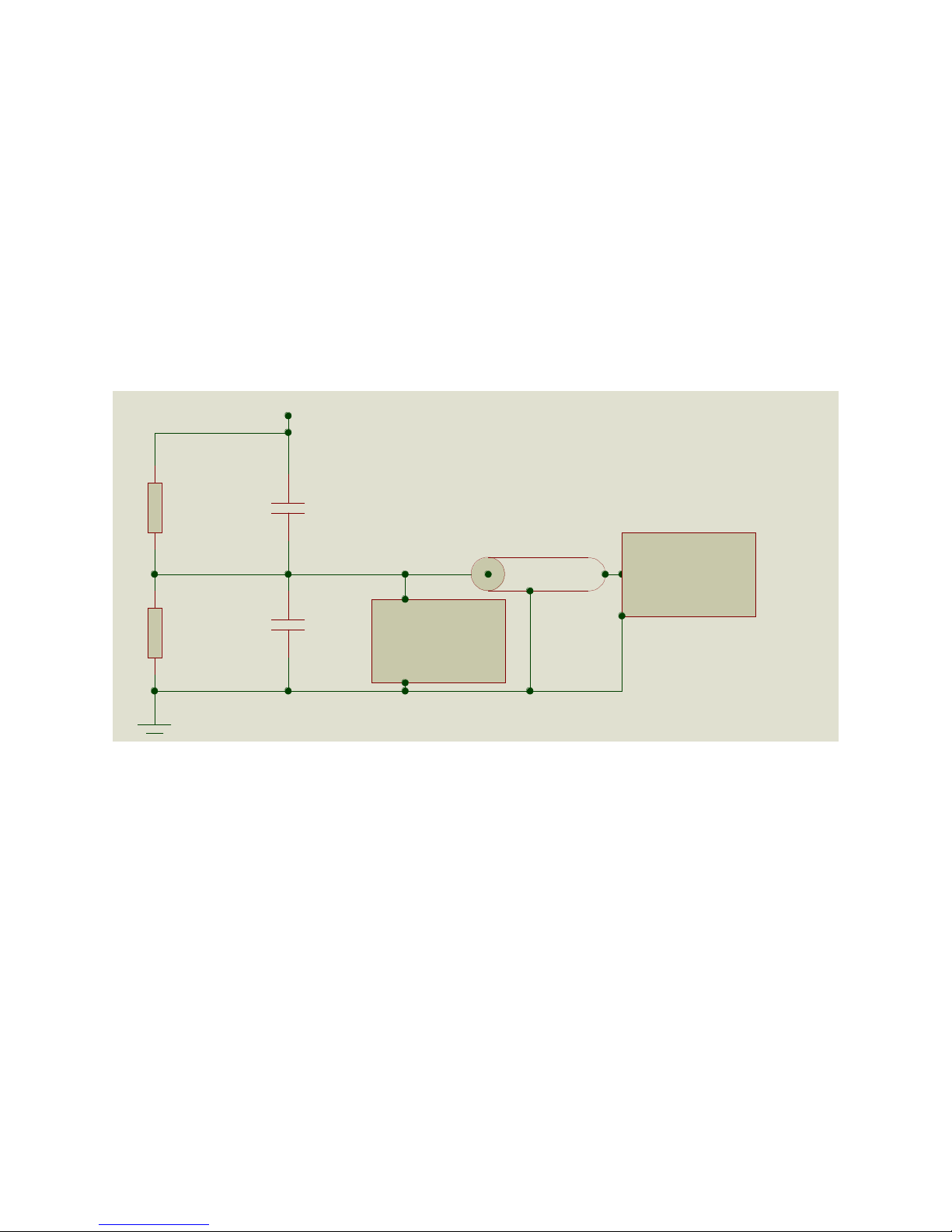
RHV
CHV
RLOW
CLOW
Scope or Meter
Connection Coax
Additional
Compensation
HV Input
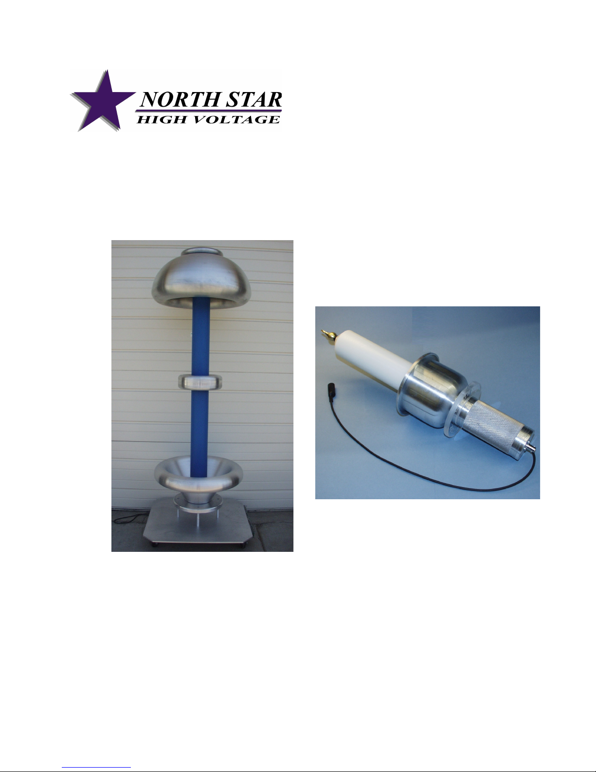
The PVM and VD series high voltage probes are RC dividers designed to produce
precisely attenuated signals over a very wide bandwidth. The circuit diagram is shown
below. The divider network consists of a high voltage network represented by a parallel
capacitor and resistor, and a low voltage network which consists of a parallel RC
network and a compensation circuit. The high voltage section of the voltage divider is in
a polypropylene oil filled housing. The low voltage section is in the small rectangular
box or circuit board inside the bottom of the handle (PVM series probes) or in the small
rectangular box underneath the probe base (VD series probes). The purpose served
by placing the low voltage section in a secondary enclosure is that it reduces noise.
Additional compensation for high frequencies is used in the PVM-2 and PVM-6.
Generalized Probe Configuration
The probe is designed to produce the calibrated level of output with a 1 Megohm
impedance on the measurement device, and with the specified cable length in place.
Changes in cable length tend to change the calibration approximately 0.5 %/ft. for a
typical 1000:1 probe. The 10,000:1 probes, including the VD series probes, have
smaller variations in calibration with cable length.
The high voltage section of each probe is insulated with Shell Diala-AX or Ergon Hivolt
transformer oil which does not contain PCBs. The oil does not have any known toxic
effects. It is the same transformer oil used throughout the world in distribution
transformers.

Input Impedance for Standard Operation
Standard probes are designed to operate into a 1 megohm oscilloscope. Operation into
higher impedance devices such as multi-meters requires a parallel resistance for
accurate measurement. For example, a 1.111 Megohm resistance can be placed in
parallel with a yellow Fluke meter (10 Megohm input) to produce a 1 Megohm input
impedance. Operation into lower impedance equipment requires factory changes.
Read the manual of your measuring instrument to determine its input impedance since
many meter manufacturers use different input impedances on different meter scales.
Erroneous readings will result with all passive probes (not just our probes) when the
wrong measurement impedance is used.
Proximity Effect and Exclusion Zone for VD and PVM11/12 Probes
The “proximity effect” (change in calibration when the probe is near ground or near a
high voltage node) has been reduced or eliminated in all NS probes. Good practice and
high voltage safety still dictate that the probe should be spaced away from other
conductors by a distance of at least 3 mm/kV (15 cm if the DC voltage is 50 kV). This is
particularly true of DC voltage and repetitive AC voltage. A high frequency (f>50 Hz)
calibration shift of about 0.5 - 1 % is possible if conductors are closer.
Proximity Effect for PVM-1 – PVM-7, PVM-100
The PVM-1 – PVM-7 use a unique shielded design which both reduces proximity effects
and increases the “speed” of measurement into the low nanosecond regime. Proximity
effect at reasonable distances (15 cm) are too low to measure in the PVM1- PVM6
probes. The PVM-100 also has a shielded design.
High Frequency Measurements
It may be necessary to improve the grounding of the probe in order to clean up noise in
very high voltage, high frequency (>20 Mhz) measurements. Specifically, a wide area
ground from the bottom of the probe, or additional individual grounds may be required.
It may also be necessary to further shield the probe cables at the highest frequencies.
The cause of noise is often the ground loop which results if the probe cable carries
some of the ground current. Inductive isolators on the probe signal cable can also be
helpful in “choking” ground currents. Note that the impedance presented to the load at
50 Mhz with a probe with 8 pf. Input capacitance is only 400 ohms, so currents matter at
high frequencies.
Connections
In general, the ground clip lead should be connected to the ground of the equipment
under test, and the tip of the probe should be connected to the voltage source for PVM
series probes. For VD series probes, the signal is connected to the top of the probe,
and the ground is connected to the base. At high frequency, the inductance of the

ground path must also be minimized. One method of improving high speed
measurement is to use multiple grounds in addition to the black ground lead provided.
The cylindrical ground shield can also be used for ground connections. Wide area and
large diameter conductors can be helpful in reducing inductance which is important for
measurements involving frequencies above 10 Mhz (30 ns rise of faster).
Connections should be made with the equipment to be measured turned off. The BNC
output cable should be connected directly to the oscilloscope, and in general the
oscilloscope should be grounded. An RG-223 cable (double shielded cable) is provided
with all probes. The double shielded cable is essential at high frequencies and it is
advantageous at low frequencies. Any 50 ohm (or 93 ohm if appropriate) cable can be
used to connect to the measurement instrument as long as that cable has the right
capacitance, but single shielded cables have more noise than the double shielded
cables we always provide.
It is important to avoid setups where the current of the source returns through the
ground shield of the probe. The probe is not designed for this, and the IR drop over the
cable appears as an erroneous signal at the oscilloscope.
Changing the Cable
We recommend that if a different cable than originally supplied is to be used, it should
be made from RG-223 cable (except for 93 ohm cable probes) and kept to the same
length as the original cable. Connectors can be placed in this cable (for example for
penetrating screen room walls). Double shielded cables (RG-223) reduce spurious
noise, leading to better performance. RG-223 has a capacitance of ~ 30.8 pf/ft.
Troubleshooting
The repair of most problems with the probe will lead to a requirement for re-calibration.
If there is a problem, dis-assembly of the probe high voltage section is not
recommended. Except in unusual situations, North Star will repair the probe without
question if it is under warranty. It is much easier for us to ascertain the problem if the
probe has not been modified by the user when it is returned to us.
If the probe has no signal output, but is not shorted to ground, the problem may be a
poor connection in the tap-off box. The tap-off box can be inspected, and if wires are
loose they should be reconnected. Do not adjust the potentiometers in the tap-off box,
or re-calibration will be required.
The largest source of problems is systems which have an unexpected input impedance
different from 1 Meg (subject to the presence of the switch option).
 Loading...