

Designed, Engineered &
Assembled in the U.S.A.
City Softener
Model NSR 17CS
How to install, operate
and maintain your
Ultra Demand Automatic
Water Conditioner
If you have any questions or concerns when
installing, operating or maintaining your water
conditioner, call our toll free number:
1-800-972-0135
or visit www.northstarwater.com
When you call, please be prepared to provide
the model and serial number of your product,
found on the rating decal, located on the rim
below the salt lid hinges.
Point-of-entry system tested and certified by
NSF International for NSF/ANSI 372, and is not
certified for material safety, contaminant reduc-
tions or structural integrity by NSF International.
Certified to
NSF/A NSI 3 72
Manufactured and warranted by
North Star Water Treatment Systems
1890 Woodlane Drive
Woodbury, MN 55125
Installation and Operation Manual
7351101 (Rev. D 6/12/17)

TABLE OF CONTENTS
Page
pecifications & Dimensions . . . . . . . . . . . . . . . . . . . . . . . . . . . . . . . . . . . . . . . . . . . . . . . . . . . . . . . . . . . . . . . . . . . 3
S
Before You Start . . . . . . . . . . . . . . . . . . . . . . . . . . . . . . . . . . . . . . . . . . . . . . . . . . . . . . . . . . . . . . . . . . . . . . . . . . . . 3
Installation Requirements . . . . . . . . . . . . . . . . . . . . . . . . . . . . . . . . . . . . . . . . . . . . . . . . . . . . . . . . . . . . . . . . . . . . 4-5
Installation Instructions . . . . . . . . . . . . . . . . . . . . . . . . . . . . . . . . . . . . . . . . . . . . . . . . . . . . . . . . . . . . . . . . . . . . . . 6-9
rogramming the Water Softener . . . . . . . . . . . . . . . . . . . . . . . . . . . . . . . . . . . . . . . . . . . . . . . . . . . . . . . . . . . . 10-11
P
Customizing Features / Options . . . . . . . . . . . . . . . . . . . . . . . . . . . . . . . . . . . . . . . . . . . . . . . . . . . . . . . . . . . . . 11-14
aintenance . . . . . . . . . . . . . . . . . . . . . . . . . . . . . . . . . . . . . . . . . . . . . . . . . . . . . . . . . . . . . . . . . . . . . . . . . . . . 15-16
M
Wiring Schematic . . . . . . . . . . . . . . . . . . . . . . . . . . . . . . . . . . . . . . . . . . . . . . . . . . . . . . . . . . . . . . . . . . . . . . . . . . 16
Troubleshooting . . . . . . . . . . . . . . . . . . . . . . . . . . . . . . . . . . . . . . . . . . . . . . . . . . . . . . . . . . . . . . . . . . . . . . . . . 17-19
Exploded View & Parts List . . . . . . . . . . . . . . . . . . . . . . . . . . . . . . . . . . . . . . . . . . . . . . . . . . . . . . . . . . . . . . . . 20-23
Bypass Blending Valve . . . . . . . . . . . . . . . . . . . . . . . . . . . . . . . . . . . . . . . . . . . . . . . . . . . . . . . . . . . . . . . . . . . . . . 24
Inspect Shipment
The parts required to assemble and install the water
softener are included with the unit. Thoroughly check
the water softener for possible shipping damage and
parts loss. Also inspect and note any damage to the
Remove and discard (or recycle) all packing materials.
To avoid loss of small parts, we suggest you keep the
small parts in the parts bag until you are ready to use
them.
shipping carton.
WATER CONDITIONER WARRANTY
Warrantor: North Star Water Treatment Systems, 1890 Woodlane Drive, Woodbury, MN 55125
Warrantor guarantees, to the original owner, that:
One Year Full Warranty:
● For a period of one (1) year from the date of purchase, all parts will be free from defects in materials and workmanship and will perform their normal functions.
Limited Warranties:
● For a period of ten (10) years from the date of purchase, the salt storage tank and fiberglass mineral tank will not rust,
corrode, leak, burst, or in any other manner, fail to perform their proper functions.
● For a period of three (3) years from the date of purchase, the electronic control board and valve body will be free of
defects in materials and workmanship and will perform their normal functions.
If, during such respective period, a part proves to be defective, Warrantor will ship a replacement part directly to your
home, without charge.
General Provisions
Damage to any part of this water conditioner because of misuse, misapplication, neglect, alteration, accident, installation or
operation contrary to our printed instructions, or damage caused by any unusual force of nature such as, but not limited to,
freezing, flood, hurricane, tornado, or earthquake is not covered by this warranty. In all such cases, regular parts and service charges will apply.
We assume no warranty liability in connection with this water conditioner other than specified herein. This warranty is in
lieu of all other warranties, expressed or implied, including warranties of fitness for a particular purpose. We do not authorize any person or representative to assume for us any other obligations on the sale of this water conditioner.
Should a defect or malfunction occur, contact your contractor. If you are unable to contact your contractor, return the part,
freight prepaid, directly to the factory at the address below. Enclose with the part a full description of the problem, with
your name, full address, date purchased, model and serial numbers, and selling contractor's name and address. We will
repair or replace the part and return it to you at no cost if our repair department determines it to be defective under the
terms of the warranty.
This warranty gives you specific legal rights and you may have other rights which vary from state to state.
This water conditioner is manufactured by
North Star Water Treatment Systems, 1890 Woodlane Drive, Woodbury, MN 55125
Customer Information Telephone No. 1-800-972-0135
2
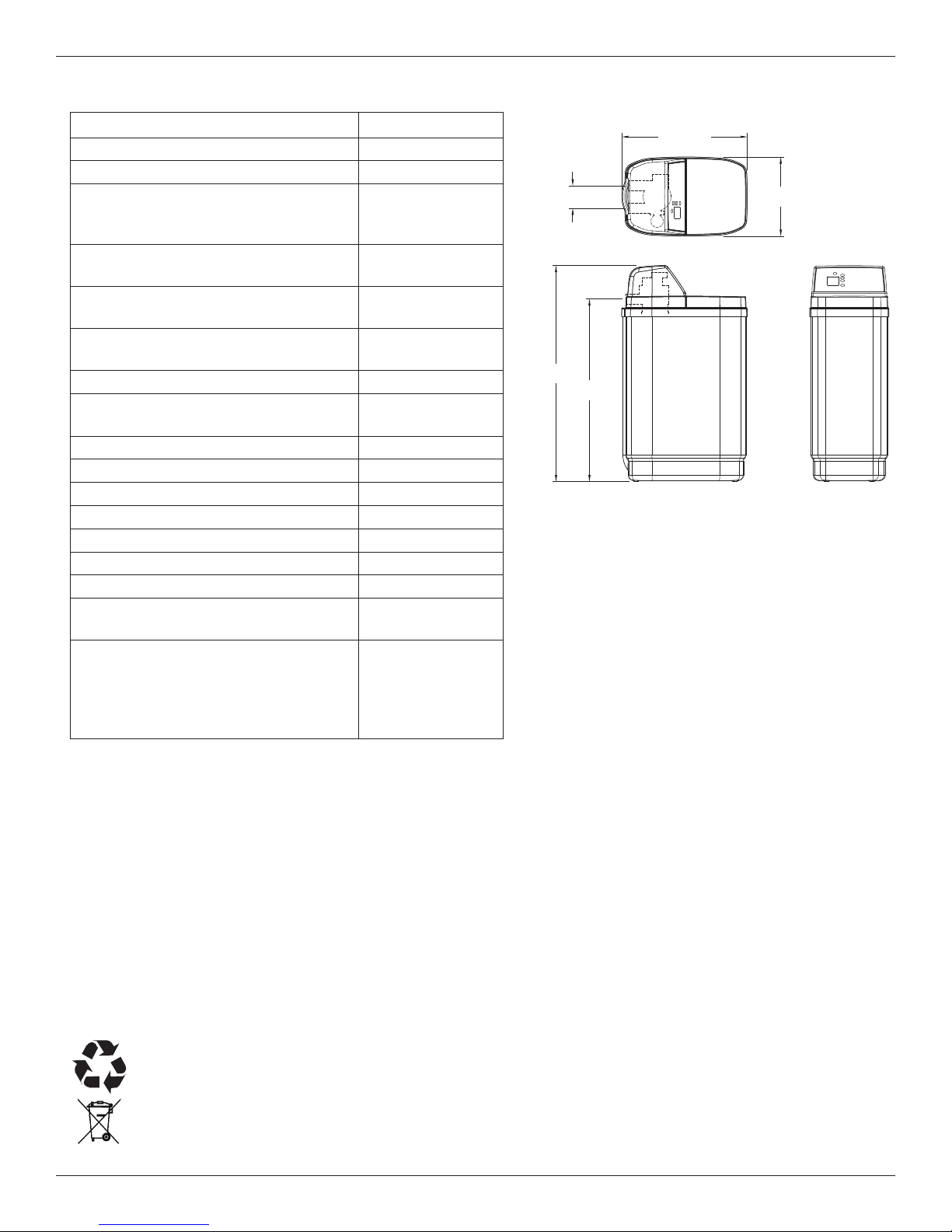
Specifications & Dimensions
Model NSR 17CS
odel Code CS17
M
Nominal Media Tank Size 9” dia. x 35”
Softening Capacity
(Grains @ Salt Dose)
Efficiency (Grains/Pound of Salt
@ Min. Salt Dose)
Water Used During Regeneration
@ Min. Salt Dose
Total Water Used Per Regeneration
@ Max. Salt Dose
Service Flow Rate 6.0 gpm
Amount of High Capacity Ion
Exchange Resin
Amount of Activated Carbon 0.21 cu. ft.
Pressure Drop at Service Flow Rate 9.0 psig
Water Supply Max. Hardness 50 gpg
Intermittent Flow* @ 15 PSI 8.2 gpm
Water Pressure Limits (min. / max.) 20 - 125 psi
Water Temperature Limits (min./ max.) 40 - 120 °F
Minimum Water Supply Flow Rate 3 gpm
Maximum Flow Rate to Drain during
Recharge
0.50 ppm
Capacity at 0.75 ppm
Chlorine Concentration** of: 1.0 ppm
1.5 ppm
2.0 ppm
9,388 @ 1.85 lbs.
4,175 @ 3.12 lbs.
1
18,951 @ 5.66 lbs.
5,075 @ 1.85 lbs.
4.8 gal. /
1,000 grains
46.2 gallons
0.62 cu. ft.
2.0 gpm
1,770,000 gal.
1,160,000 gal.
870,000 gal.
580,000 gal.
450,000 gal.
18-7/8”
IN
3-3/8”
OUT
IN - OUT
42”
37”
1-7/8”
1
FIG. 1
*Intermittent flow rate does not represent the maxi-
mum service flow rate used for detemining the conditioner’s rated capacity and efficiency. Continuous
operation at flow rates greater than the service flow
rate may affect capacity and efficiency performance.
**Typical residential chlorine concentration is 0.5 to 1.0
ppm.
Variable Salt Dose: The salt dose is selected by
the electronic controls at regeneration time based
on the amount needed.
= The water softener requires a minimum water flow of 3 gallons per minute at the inlet. Maximum allowable inlet
water pressure is 125 psi. If your house water pressure is over the maximum, install a pressure reducing valve in
the water supply pipe to the system (Adding a pressure reducing valve may reduce the flow). If your home is
equipped with a back flow preventer, an expansion tank must be installed in accordance with local codes and laws.
= The water softener works on 24V DC electrical power, supplied by a direct plug-in power supply (included). Be
sure to use the included power supply and plug it into a nominal 120V, 60 Hz household outlet that is in a dry
location only, grounded and properly protected by an overcurrent device such as a circuit breaker or fuse.
= Do not use this system to treat water that is microbiologically unsafe or of unknown quality without adequate dis-
infection upstream or downstream of the system.
European Directive 2002/96/EC requires all electrical and electronic equipment to be disposed of accord-
ing to Waste Electrical and Electronic Equipment (WEEE) requirements. This directive or similar laws are
in place nationally and can vary from region to region. Please refer to your state and local laws for proper disposal of this equipment.
Before You Start
3
Installation Requirements
LOCATION REQUIREMENTS
Consider all of the following when selecting an installation location for the water softener.
= Do not locate the water softener where freezing
temperatures occur. Do not attempt to treat water
over 120ºF. Freezing temperatures or hot water
damage voids the warranty.
= To condition all water in the home, install the water
softener close to the water supply inlet, and
upstream of all other plumbing connections, except
outside water pipes. Outside faucets should remain
on hard water to avoid wasting conditioned water
and salt.
= A nearby drain is needed to carry away regenera-
tion discharge (drain) water. Use a floor drain,
laundry tub, sump, standpipe, or other options
(check your local codes). See "Air Gap
Requirements" and "Valve Drain Requirements"
sections.
= The water softener works on 24V DC electrical
power, supplied by a direct plug-in power supply
(included). Provide nearby a 120V, 60 Hz electrical
outlet, in accordance with national and local codes.
= Always install the water softener between the water
inlet and water heater. Any other installed water
conditioning equipment should be installed between
the water inlet and water softener (See Figure 3
below).
= Avoid installing in direct sunlight. Excessive sun
heat may cause distortion or other damage to nonmetallic parts.
PLUMBING CODES
All plumbing must be completed in accordance with
national, state and local plumbing codes.
In the state of Massachusetts: The Commonwealth
of Massachusetts plumbing code 248-CMR shall
be adhered to. A licensed plumber shall be used
for this installation.
AIR GAP REQUIREMENTS
A drain is needed for regeneration water (See Figure
2). A floor drain, close to the water softener, is preferred. A laundry tub, standpipe, etc. are other drain
options. Secure valve drain hose in place. Leave an
air gap of 1-1/2” between the end of the hose and the
drain. This gap is needed to prevent backflow of
sewer water into the water softener. Do not put the
end of the drain hose into the drain.
1-1/2”
air gap
FLOOR DRAIN
Drain
Hose
1-1/2”
air gap
Drain
Hose
1-1/2”
air gap
LAUNDRY TUBSTANDPIPE
Drain
Hose
FIG. 2
THE PROPER ORDER TO INSTALL WATER TREATMENT EQUIPMENT
Untreated Water to
Cold Water
to House
Hot Water
to House
Outside Faucets
Water
Heater
Softener
Water
Optional
Sediment
Filter
City Water Supply
Pressure
Tank
Well Water Supply
OR
Well
Pump
FIG. 3
4
Installation Requirements
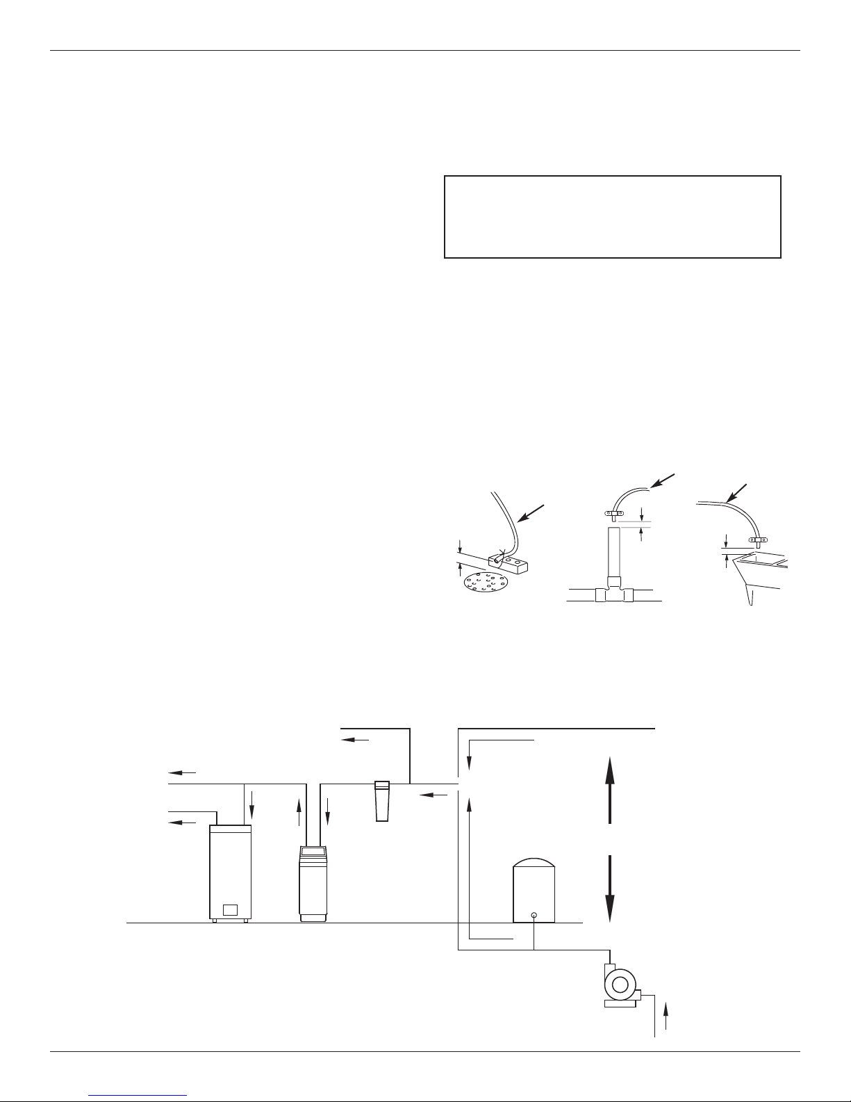
VALVE DRAIN REQUIREMENTS
Using the flexible drain hose (included), measure and
cut to the length needed. Flexible drain hose is not
allowed in all localities (check your plumbing codes). If
local codes do not allow use of a flexible drain hose, a
rigid valve drain run must be used. Purchase a compression fitting (1/4 NPT x 1/2” minimum tube) and
1/2” tubing from your local hardware store. Plumb a
rigid drain as needed (See Figure 5).
NOTE: Avoid drain hose runs longer than 30 feet.
Avoid elevating the hose more than 8 feet
above the floor. Make the valve drain line as
short and direct as possible.
1/4” NPT
Thread
Clip
Cut barbs from drain fit-
ting (pull clip to remove
1/4 NPT
Threads
Barbs
fitting from valve)
Barbs for 3/8”
I.D. Tubing
Hose Clamp
Drain Hose
FIG. 4
Compression Fitting.
1/4 NPT x 1/2” O.D.
Tube (not included)
1/2” Outside Dia.
Copper Tube
(not included)
FIG. 5
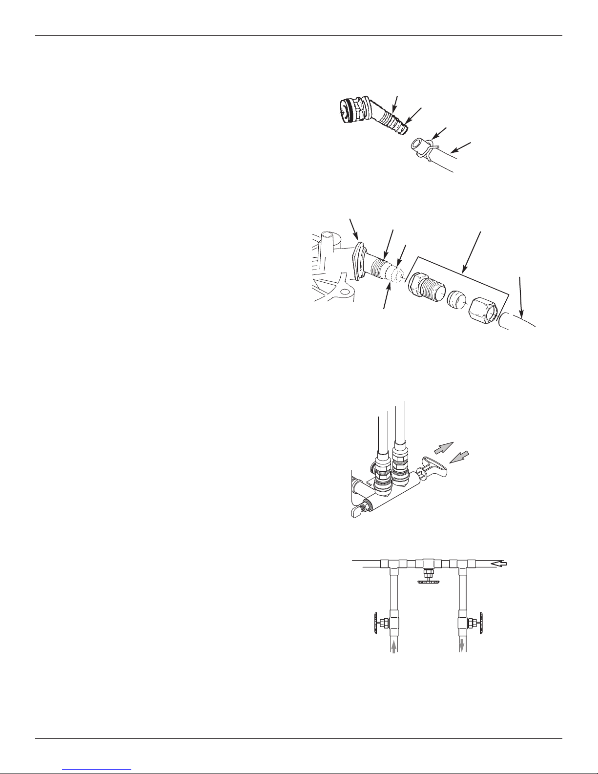
INLET / OUTLET PLUMBING OPTIONS
Always install either a single bypass valve (provided),
as shown in Figure 6, or, if desired, parts for a 3 valve
bypass system (not included) can be purchased and
assembled, as shown in Figure 7. Bypass valves
allow you to turn off water to the softener for maintenance if needed, but still have water in house pipes.
Pipe fittings must be 3/4” minimum.
Use:
= Copper pipe
= Threaded pipe
= PEX (Crosslinked Polyethylene) pipe
= CPVC plastic pipe
= Other pipe approved for use with potable water
IMPORTANT: Do not solder with plumbing attached to
installation adaptors and single bypass
valve. Soldering heat will damage the
adaptors and valve.
Outlet
Valve
SINGLE BYPASS VALVE
Pull out for “Service”
(Soft water)
Push in for
“Bypass”
3 VALVE BYPASS
Bypass
Valve
From Water
Softener
To Water
Softener
FIG. 6
Inlet
Valve
FIG. 7
5
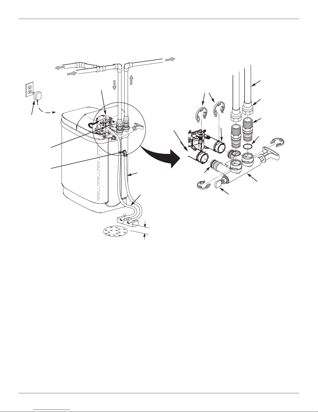
Installation Instructions
TYPICAL INSTALLATION
To Outside
Faucets
To
Controller
Plug-in
Power
Supply
Valve Drain
Elbow
Overflow
Drain Elbow
*Do not connect
the water softener
valve drain tubing
to the salt storage
tank overflow
hose.
Hard Water
Water Softener
V
alve
a
W
n
i
a
M
Floor Drain
pe
Pi
r
te
Salt Storage
Tank Overflow
Hose*
Inlet
Valve Drain
Hose*
Secure Valve Drain
Hose in place over
Floor Drain
1-1/2”
air gap
Conditioned
Water
Lubricated
O-ring
Pipe
Clips
Outlet
Blend Adjusting Knob
(See Page 24 for instructions)
NOTE: See “Air Gap Requirements” section.
NOTE: Water Softener shown with Salt Lid
and Top Cover removed
1” NPT Sweat
Adaptor (not
included)
1” NPT
Threaded
Adaptor
O-ring
Single
Bypass Valve
FIG. 8
TURN OFF WATER SUPPLY
1. Close the main water supply valve, located near the
well pump or water meter.
2. Shut off the electric or fuel supply to the water
heater.
3. Open all faucets to drain all water from house pipes.
NOTE: Be sure not to drain water from the water
heater, as damage to the water heater elements could result.
ASSEMBLY
1. North Star models are factory assembled. During
installation, remove the salt lid and set it aside to
prevent damage. Check the brinewell to be sure it
is secured and vertical (See Figure 11). Unsnap the
faceplate cover to expose the softener valve assembly.
2. Lift the brine valve out of the brinewell. Make sure
the float stem is parallel to the stand tube so the
seals will seat properly during operation. Place the
brine valve back into the bottom of the brinewell and
reinstall the brinewell cover.
3. Install the brine tank overflow grommet and elbow
into the 13/16” diameter hole in the back of the salt
storage tank wall.
MOVE THE UNIT INTO PLACE
1. Move the water softener into the desired location.
Set it on a solid, level surface.
IMPORTANT: Do not place shims directly under the
salt storage tank to level the softener.
The weight of the tank, when full of
water and salt, may cause the tank to
fracture at the shim.
continued on next page
6
Installation Instructions
ontinued from previous page
c
2. Visually check and remove any debris from the
ater softener valve inlet and outlet ports.
w
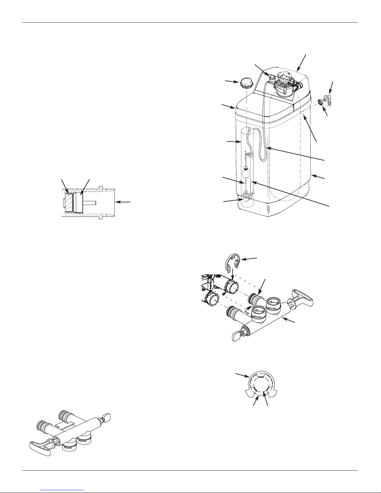
. Make sure the turbine assembly spins freely in the
3
"out" port of the valve (See Figure 9).
4. If not already done, put a light coating of silicone
grease on the single bypass valve o-rings.
5. Push the single bypass valve into the softener valve
as far as it will go. Snap the two large holding clips
into place, from the top down as shown in Figures
12 & 13.
IMPORTANT: Be sure the clips snap firmly into place
so the single bypass valve will not pull
out.
Turbine
Turbine Support Assembly
Valve Outlet
FIG. 9
Brinewell
Cover
Salt
Lid
Brinewell
Float
Stem
Brine
Valve
Nozzle
Venturi
Assembly
Top Cover
Brine Tank
O
Elbow
Brine Tank
Overflow
Grommet
13/16” Hole
Brine
Tubing
Salt
Storage
Tank
verflow
Stand
Tube
COMPLETE INLET AND OUTLET PLUMBING
Measure, cut, and loosely assemble pipe and fittings
from the main water pipe to the inlet and outlet ports of
the water softener valve. Be sure to keep fittings fully
together, and pipes squared and straight.
Be sure hard water supply pipe goes to the water softener valve inlet side.
NOTE: Inlet and outlet are marked on the water sof-
tener valve. Trace the water flow direction to
be sure hard water is to inlet.
IMPORTANT: Be sure to fit, align and support all
plumbing to prevent putting stress on
the water softener valve inlet and outlet.
Undue stress from misaligned or unsupported plumbing may cause damage to
the valve.
Complete the inlet and outlet plumbing for the type of
pipes you will be using.
ALTERNATE BYPASS VALVE INSTALLATION
If connecting to floor
level plumbing, install
the bypass valve turned
downward, as shown.
OUT
IN
FIG. 10
FIG. 11
Clip
Channel
Single Bypass Valve
FIG. 12
Correct Assembly
Clip
Outside diameter
of water softener
valve inlet & outlet
NOTE: Be sure all 3 tabs of the clip go through the matching
holes on the water softener valve inlet or outlet, and
fully into the channel on the single bypass valve.
Make sure that the tabs are fully seated.
Outside diameter
of clip channel on
single bypass valve
FIG. 13
7
Installation Instructions
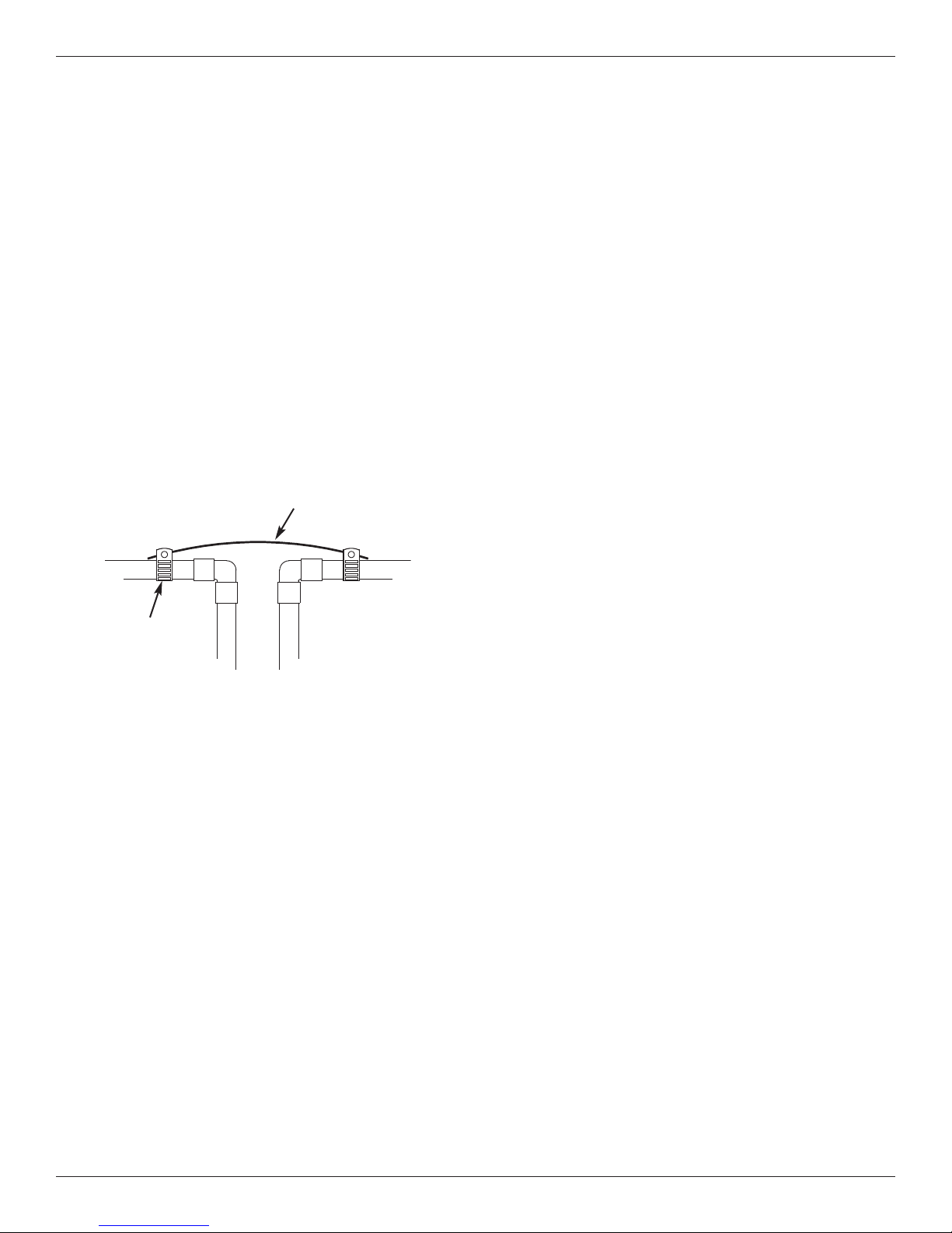
GROUNDING INFORMATION
(for Installations on Metal Pipe)
The house main incoming water pipe is often used to
ground electrical outlets in the home. Grounding protects you from electrical shock. Installing the water
softener with a plastic bypass valve will break this
ground. Before beginning installation, purchase and
securely install two grounding clamps and a #4 copper
wire across the location where the softener will be,
tightly clamping it at both ends, as shown in Figure 14.
NOTE: Check local plumbing and electrical codes
for proper installation of the ground wire.
The installation must conform to them. In
Massachusetts, plumbing codes of
Massachusetts shall be conformed to.
Consult with your licensed plumber.
Ground Wire
(not included)
Clamp
(2 - not included)
FIG. 14
INSTALL VALVE DRAIN HOSE
NOTE: See valve drain options on page 4.
1. Measure, cut to needed length and connect the 3/8”
drain line (provided) to the water softener valve
drain fitting. Use a hose clamp to hold the hose in
place.
IMPORTANT: If codes require a rigid drain line see
“Valve Drain requirements" section.
2. Run the drain hose (or a rigid line) to the floor drain.
Secure drain hose. This will prevent “whipping'' during regenerations. Be sure to provide a 1-1/2” min -
imum air gap to prevent possible sewer water
backup. See “Air Gap Requirements" section.
NOTE: In addition to a floor drain, you can use a laun-
dry tub or standpipe as a good drain point for
this hose.. Avoid long drain hose runs, or elevating the hose more than 8 feet above the
floor.
INSTALL SALT STORAGE TANK OVERFLOW HOSE
1. Measure, cut to needed length and connect the 3/8”
drain line (provided) to the salt storage tank overflow elbow and secure in place with a hose clamp.
2 Route the hose to the floor drain, or other suitable
drain point no higher than the drain fitting on the salt
storage tank (This is a gravity drain). If the tank
overfills with water, the excess water flows to the
drain point. Cut the drain line to the desired length
and route it neatly out of the way.
IMPORTANT: For proper operation of the water soften-
er, do not connect the water softener
valve drain tubing to the salt storage
tank overflow hose.
TEST FOR LEAKS
To prevent air pressure in the water softener and
plumbing system, complete the following steps in
order:
1. Fully open two or more softened cold water faucets
close to the water softener, located downstream
from the water softener.
2. Place the bypass valve (single or 3 valve) into the
"bypass" position. See Figures 6 & 7 on Page 5.
3. Slowly open the main water supply valve. Run
water until there is a steady flow from the opened
faucets, with no air bubbles.
4. Place bypass valve(s) in "service" or soft water position as follows:
= Single bypass valve: Slowly move the valve stem
toward "service," pausing several times to allow
the water softener to fill with water.
= 3 valve bypass: Fully close the bypass valve and
open the outlet valve. Slowly open the inlet
valve, pausing several times to allow the water
softener to fill with water.
5. After about three minutes, open a hot water faucet
until there is a steady flow and there are no air bubbles, then close this faucet.
6. Close all cold water faucets and check for leaks at
the plumbing connections that you made.
7. Check for leaks around clips at softener’s inlet and
outlet. If a leak occurs at a clip, depressurize the
plumbing (turn off the water supply and open
faucets) before removing clip. When removing clips
at the softener’s inlet or outlet, push the single
bypass valve body toward the softener (See Figure
15). Improper removal may damage clips. Do not
reinstall damaged clips.
8
 Loading...