

North Star NSLA1683066 Owner's Manual
READ & SAVE THESE INSTRUCTIONS
30-Gallon Electric Air Compressor
Owner’s Manual
WARNING: Read carefully and understand all ASSEMBLY AND OPERATION
INSTRUCTIONS before operating. Failure to follow the safety rules and other basic safety
precautions may result in serious personal injury.
Item #75859

Page 2 of 36
Thank you very much for choosing a NorthStar® product!
For future reference, please complete the owner’s record below:
Serial Number/Lot Date Code: ________________________________
Purchase Date: ____________________________________________
Save the receipt, warranty, and this manual. It is important that you read
the entire manual to become familiar with this product before you begin
using it.
This air compressor is designed for certain applications only. Northern
Tool and Equipment is not responsible for issues arising from
modification or improper use of this product such as an application for
which it was not designed. We strongly recommend that this product not
be modified and/or used for any application other than that for which it
was designed.
For technical questions, please call 1-888-895-4549.

Page 3 of 36
Table of Contents
Intended Use .......................................................................................................................................... 5
Packaging Contents .............................................................................................................................. 5
Technical Specifications ...................................................................................................................... 5
Safety Signal Words ............................................................................................................................. 5
Important Safety Information ............................................................................................................... 6
Specific Operation Warnings ............................................................................................................... 9
Main Parts of Compressor ................................................................................................................. 10
Hot Surfaces ........................................................................................................................................ 11
Assembly ............................................................................................................................................. 12
Attaching Vibration Pads ................................................................................................................ 12
Installing Hoses .............................................................................................................................. 12
Disconnecting Hoses ...................................................................................................................... 13
Installation ........................................................................................................................................... 13
Lubrication and Oil .......................................................................................................................... 13
Compatibility ................................................................................................................................... 13
Location .......................................................................................................................................... 13
Humid Areas ................................................................................................................................... 13
Wiring ................................................................................................................................................... 13
Wiring Instructions .......................................................................................................................... 14
Grounding ............................................................................................................................................ 14
Grounding Instructions ................................................................................................................... 14
Extension Cords .................................................................................................................................. 15
Voltage and Circuit Protection .......................................................................................................... 16
Motor Reset ......................................................................................................................................... 16
Motor Reset Switch ........................................................................................................................ 16
How to Use Your Unit ......................................................................................................................... 17
How to Stop .................................................................................................................................... 17
Break-In Procedure ........................................................................................................................ 17
Before Each Start-Up .......................................................................................................................... 18
Operating Instructions ........................................................................................................................ 19
How to Start .................................................................................................................................... 19
After Each Use ..................................................................................................................................... 19
Maintenance ........................................................................................................................................ 20
Checking Safety Valve ................................................................................................................... 21
Checking Air Filter .......................................................................................................................... 21
Draining Air Tank ............................................................................................................................ 21

Page 4 of 36
Pump Oil............................................................................................................................................... 22
Compressor Pump Oil .................................................................................................................... 22
Checking Oil ................................................................................................................................... 22
Changing Oil ................................................................................................................................... 22
Belt Replacement / Belt Tension / Motor Pulley & Flywheel Adjustment ...................................... 23
Belt Replacement ........................................................................................................................... 23
Adjusting Belt Tension .................................................................................................................... 24
Motor Pulley/Flywheel Alignment ................................................................................................... 24
Air Compressor Pump Intake and Exhaust Valves ........................................................................ 24
Inspect Air Lines and Fittings for Leaks ......................................................................................... 25
Air Compressor Head Bolts - Torqueing ........................................................................................ 25
Service and Adjustments ................................................................................................................ 25
To Replace or Clean Check Valve ................................................................................................. 25
Troubleshooting .................................................................................................................................. 26
Air Compressor Parts Diagram ......................................................................................................... 30
Air Compressor Parts List.................................................................................................................. 30
Pump Parts Diagram ........................................................................................................................... 32
Pump Parts List ................................................................................................................................... 32
Replacement Parts .............................................................................................................................. 33
Limited Warranty ................................................................................................................................. 34

Page 5 of 36
Intended Use
The NorthStar 30-Gallon Electric Air Compressor provides compressed air for air tools and pressurized
objects that require high air pressure. It features:
• Maximum Efficiency: Heavy-duty induction motor for maximum performance and efficiency.
• Long Lasting Operation: Cast iron oil-lubricated pump for long service life.
• Versatile Operation: Dual voltage motor is wired for standard 120V outlets but can be converted to
240V applications.
Note: Do not use for low-pressure objects such as balloons, air mattresses, and sport balls, which can
explode quickly and easily. Special precautions are necessary when used for cleaning to prevent flying
debris hazards. It is not to be used to supply breathing air.
Packaging Contents
• Air Compressor
• Isolator C-Channel Vibration Pads (2)
• Owner’s Manual
• Compressor Insert Sheet
Technical Specifications
Property
Specification
Model
NSLA1683066
Weight
165 lb. (75 kg)
Height
48”
Width
24.12”
Running HP
1.6
Tank Capacity
30 Gallons
Voltage/Amps/Phase
120/240 Volts / 15/7.5 Amps / 1 Phase
Kick-in Pressure
125 PSI (8,62 bar)
Kick-out Pressure
155 PSI (10,69 bar)
Air Delivery
5.3 CFM @ 90 PSI
6.2 CFM @ 40 PSI
Noise Rating
77 dB
Pump Type
Belt Drive
Safety Signal Words
The definitions below describe the level of severity for each signal word. Please read the manual and pay
attention to these symbols.
DANGER: Indicates an imminently hazardous situation which, if not avoided, will result in death
or serious injury.
WARNING: Indicates a potentially hazardous situation which, if not avoided, could result in death
or serious injury.
CAUTION: Indicates a potentially hazardous situation which, if not avoided, may result in minor or
moderate injury.
NOTICE: Indicates a practice not related to personal injury which, if not avoided, may result in
property damage.

Page 6 of 36
Important Safety Information
⚠WARNING
• Read and understand all instructions. Failure to follow all instructions may result in serious injury or
property damage.
• The warnings, cautions, and instructions in this manual cannot cover all possible conditions or
situations that could occur. Exercise common sense and caution when using this tool. Always be
aware of the environment and ensure that the tool is used in a safe and responsible manner.
• Do not allow persons to operate or assemble the product until they have read this manual and have
developed a thorough understanding of how it works.
• Do not modify this product in any way. Unauthorized modification may impair the function and/or
safety and could affect the life of the product. There are specific applications for which the product
was designed.
• Use the right tool for the job. DO NOT attempt to force small equipment to do the work of larger
industrial equipment. There are certain applications for which this equipment was designed. This
product will be safer and do a better job at the capacity for which it was intended. DO NOT use this
equipment for a purpose for which it was not intended.
• Industrial or commercial applications must follow OSHA requirements.
⚠WARNING
PROP 65
• This product can expose you to chemicals including lead, which is known to the State of California to
cause cancer and birth defects or other reproductive harm. For more information, go to
www.p65warnings.ca.gov.
⚠WARNING
WORK AREA SAFETY
• Inspect the work area before each use. Keep work area clean, dry, free of clutter, and well-lit.
Cluttered, wet, or dark work areas can result in injury. Using the product in confined work areas may
put you dangerously close to cutting tools and rotating parts.
• Do not use the product where there is a risk of causing a fire or an explosion; e.g., in the presence of
flammable liquids, gases, or dust. The product can create sparks, which may ignite the flammable
liquids, gases, or dust.
• Do not allow the product to come into contact with an electrical source. The tool is not insulated and
contact will cause electrical shock.
• Keep children and bystanders away from the work area while operating the tool. Do not allow children

Page 7 of 36
to handle the product.
• Be aware of all power lines, electrical circuits, water pipes, and other mechanical hazards in your
work area. Some of these hazards may be hidden from your view and may cause personal injury
and/or property damage if contacted.
• Keep your work area clean and well lit. Ensure floors are not slippery from wax or dust.
• The compressed air directly from your compressor is not safe for breathing. The air stream may
contain carbon monoxide, toxic vapors, or solid particles from the air tank. Breathing these
contaminants can cause serious injury or death. Never use air obtained directly from the compressor
to supply air for human consumption. The compressor is not equipped with suitable filters and in-line
safety equipment for human consumption.
• Never drill into, weld or make any modifications to the air tank or its attachments. Never attempt to
repair a damaged or leaking air tank. Replace with a new air tank.
• The air tank is designed to withstand specific operating pressures. Never make adjustments or parts
substitutions to alter the factory set operating pressures.
• Over inflation of tires could result in serious injury and property damage. NOTE: Air tanks,
compressors and similar equipment used to inflate tires can fill small tires very rapidly. Adjust
pressure regulator on air supply to no more than the rating of the tire pressure. Add air in small
increments and frequently use the tire gauge to prevent over inflation.
• Oil can leak or spill and could result in fire or breathing hazard; serious injury or death can result. Oil
leaks will damage carpet, paint or other surfaces in vehicles or trailers. Always place compressor on a
protective mat when transporting to protect against damage to vehicle from leaks. Remove
compressor from vehicle immediately upon arrival at your destination. Always keep compressor level
and never lie on its side.
⚠WARNING
PERSONAL SAFETY
• Stay alert, watch what you are doing, and use common sense when operating the tool. Do not use
the tool while you are tired or under the influence of drugs, alcohol, or medication. A moment of
inattention while operating the tool may result in serious personal injury.
• Dress properly. Do not wear loose clothing, dangling objects, or jewelry. Keep your hair, clothing and
gloves away from moving parts. Loose clothes, jewelry, or long hair can be caught in moving parts.
Air vents on the tool often cover moving parts and should be avoided.
• Wear the proper personal protective equipment when necessary. Use ANSI Z87.1 compliant safety
goggles (not safety glasses) with side shields, or when needed, a face shield. Use a dust mask in
dusty work conditions. Also use non-skid safety shoes, hardhat, gloves, dust collection systems, and
hearing protection when appropriate. This applies to all persons in the work area.
• Work in an area with good cross ventilation. Read and follow the safety instructions provided on the
label or safety data sheets for the materials you are spraying. Always use certified safety equipment:
NIOSH/OSHA respiratory protection or properly fitting face mask designed for use with your specific

Page 8 of 36
application.
• Do not overreach. Keep proper footing and balance at all times.
• Remove keys or wrenches before connecting the tool to an air supply, power supply, or turning on the
tool. A wrench or key that is left attached to a rotating part of the tool may cause personal injury.
• Secure the work with clamps or a vise instead of your hand when practical. This safety precaution
allows for proper tool operation using both hands.
• Never touch any exposed metal parts on compressor during or immediately after operation. The
compressor will remain hot for several minutes after operation. Do not reach around protective
shrouds or attempt maintenance until the unit has been allowed to cool.
• The compressed air stream can cause soft tissue damage to exposed skin and can propel dirt, chips,
loose particles and small objects at high speed, resulting in property damage or personal injury.
Never point any nozzle or sprayer toward any part of the body or at other people or animals.
⚠CAUTION
AIR COMPRESSOR USE AND CARE
• Do not force the air compressor. Products are safer and do a better job when used in the manner for
which they are designed. Plan your work and use the correct product for the job.
• Check for damaged parts before each use. Carefully check that the product will operate properly and
perform its intended function. Replace damaged or worn parts immediately. Never operate the
product with a damaged part.
• Do not use a product with a malfunctioning switch. Any power tool that cannot be controlled with the
power switch is dangerous and must be repaired by an authorized service representative before
using.
• Disconnect the power/air supply from the product and place the switch in the locked or off position
before making any adjustments, changing accessories, or storing the tool. Such preventive safety
measures reduce the risk of starting the tool accidentally.
• Store the product when it is not in use. Store it in a dry, secure place out of the reach of children.
Inspect the tool for good working condition prior to storage and before re-use.
• Use only accessories that are recommended by the manufacturer for use with your product.
Accessories that may be suitable for one product may create a risk of injury when used with another
tool. Never use an accessory that has a lower operating speed or operating pressure than the tool
itself.
• Keep guards in place and in working order. Never operate the product without the guards in place.
• Do not leave the tool running unattended.
• Drain the moisture from the tank on a daily basis. A clean, dry tank will help prevent corrosion.
• Pull the pressure relief valve ring daily to ensure that the valve is functioning properly, and to clear
the valve of any possible obstructions.

Page 9 of 36
• To provide proper ventilation for cooling, the compressor must be kept a minimum of 12 inches (31
cm) from the nearest wall, in a well–ventilated area.
• Fasten the compressor down securely if transporting is necessary. Pressure must be released from
the tank before transporting.
• Protect the air hose and electric cord from damage and puncture. Inspect them weekly for weak or
worn spots and replace if necessary.
• To reduce the risk of electric shock, do not expose to rain. Store indoors.
• Never operate the compressor if the power cord or plug are damaged. Take the equipment to the
nearest Authorized Service Center and a specialized technician will replace it.
• The compressor is too heavy to be lifted by one person. Obtain assistance from others before lifting.
Specific Operation Warnings
⚠WARNING
• Repairs attempted by unqualified personnel can result in serious injury or death by electrocution. Any
electrical wiring or repairs required on this product should be performed by authorized service center
personnel in accordance with national and local electrical codes.
• Failure to provide adequate grounding to this product could result in serious injury or death from
electrocution. Refer to Grounding Instructions paragraph in the Installation section. Make certain that
the electrical circuit to which the compressor is connected provides proper electrical grounding,
correct voltage and adequate fuse protection.
• Under some conditions and duration of use, noise from this product may contribute to hearing loss.
Always wear certified safety equipment: ANSI S12.6 (S3.19) hearing protection.
• Exceeding the pressure rating of air tools, spray guns, air operated accessories, tires and other
inflatables can cause them to explode or fly apart and could result in serious injury. Follow the
equipment manufacturer’s recommendation and never exceed the maximum allowable pressure
rating of attachments. Never use compressor to inflate small low-pressure objects such as children’s
toys, footballs, basketballs, etc.
• Drain air tank daily or after each use. If air tank develops a leak, replace it immediately with a new air
tank or replace the entire compressor.
Page 10 of 36
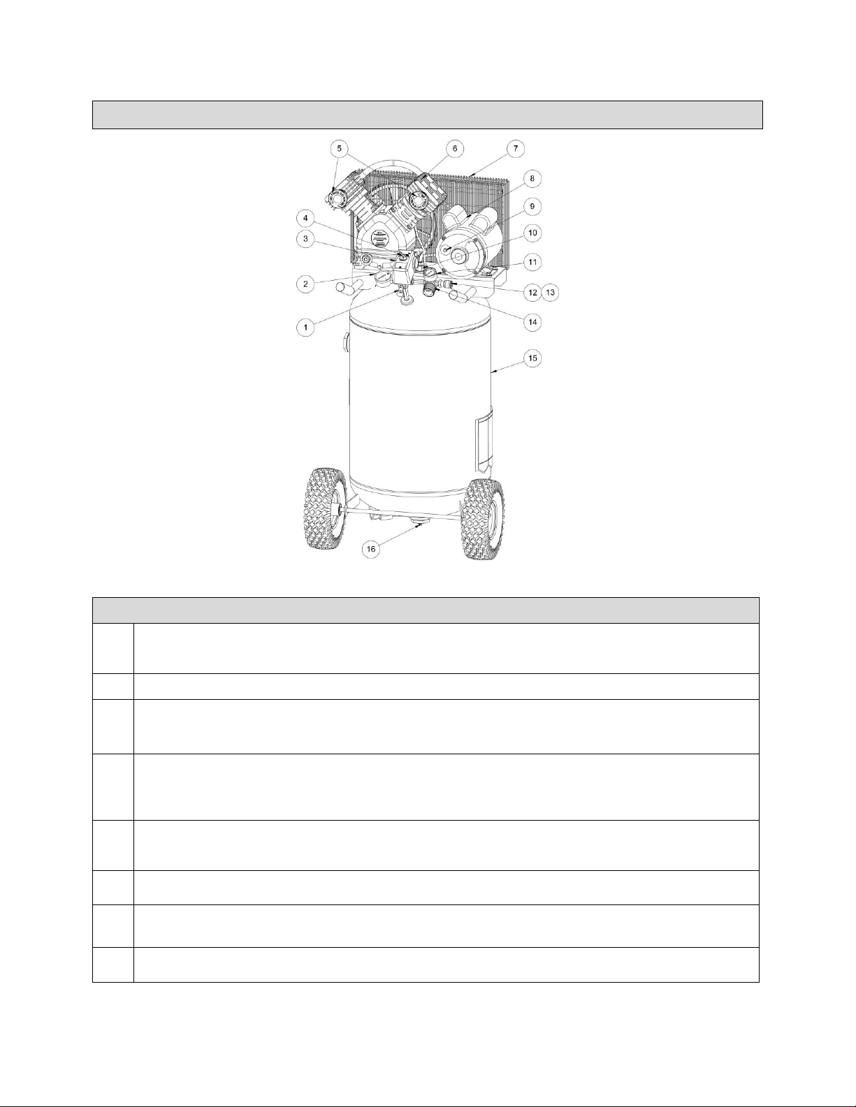
Main Parts of Compressor
Figure A
Components
1.
Safety Valve: This valve is designed to prevent system failures by relieving pressure from the
system when the compressed air reaches a predetermined level. The valve is preset by the
manufacturer and must not be removed or modified in any way.
2.
Tank Pressure Gauge: The tank pressure gauge indicates the reserve air pressure in the tank.
3.
Pressure Switch: The pressure switch automatically starts the motor when the air tank pressure
drops below the factory set cut-in pressure. It stops the motor when the air tank pressure reaches
the factory set cut-out pressure.
4.
Pressure Auto (-) / Off (O) Switch: Place this switch in the AUTO (-) position to provide automatic
power to the pressure switch and OFF (O) to remove power at the end of each use. NOTE:
ALWAYS ensure the switch is in the OFF (O) position before removing or replacing the pressure
switch cover.
5.
Air Intake Filters: The filters are designed to clean air entering the pump. To ensure the pump
continually receives a clean, cool, and dry air supply, the filters must always be clean and the filter
intakes must be free from obstructions.
6.
Air Compressor Pump: The pump compresses air into the air tank. Working air is not available until
the compressor has raised the air tank pressure above that required at the air outlet.
7.
Belt Guard: This covers the engine pulley, pump flywheel, and belt. Never operate without the belt
guard in place.
8.
Motor: The electric motor powers the pump. The electric motor is equipped with an overload
protector to help prevent possible motor burnout.
Page 11 of 36
Components
9.
Motor Overload Protector: The motor has a thermal overload protector. If the motor overheats for
any reason, the overload protector will shut off the motor. The motor must be allowed to cool down
before restarting. To restart:
1. Set the Auto/Off switch to OFF (O) and unplug unit.
2. Allow the motor to cool.
3. Depress the red reset button on the motor.
4. Plug the power cord into the correct branch circuit receptacle.
10.
Check Valve: When the air compressor is operating, the check valve is open, allowing
compressed air to enter the air tank. When the air compressor reaches cut-out pressure, the
check valve closes, allowing air pressure to remain inside the air tank.
11.
Regulated Pressure Gauge: The regulated pressure gauge indicates the air pressure available at
the outlet side of the regulator. This pressure is controlled by the regulator and is always less or
equal to the air tank pressure.
12.
Universal Quick Connect Body: The universal quick connect body accepts the three most
popular styles of quick connect plugs: Industrial, Automotive and ARO. One hand push-to-connect
operation makes connections simple and easy.
13.
Air Outlet: Connect an air hose to this outlet.
14.
Regulator: The regulator knob controls the air pressure coming from the air tank. To adjust the
regulator, turn the knob clockwise to increase regulated pressure and counter-clockwise to
decrease regulated pressure.
15.
Air Tank: The 30 Gallon ASME tank stores the compressed air.
16.
Air Tank Drain Valve: The drain valve is located at the base of the air tank and is used to drain
condensation at the end of each use.
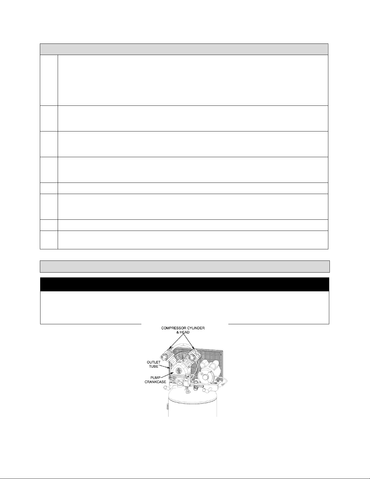
Hot Surfaces
⚠WARNING
• Never touch any exposed metal parts on compressor during or immediately after operation. The
compressor will remain hot for several minutes after operation. Do not reach around protective
shrouds or attempt maintenance until the unit has been allowed to cool.
Figure B
 Loading...