

NorthStar NS100 - RADIO, NS100 VHF Installation Sheet
Radio Installation Sheet
for NS100 VHF system
w ww .NorthstarNav.com
HLR
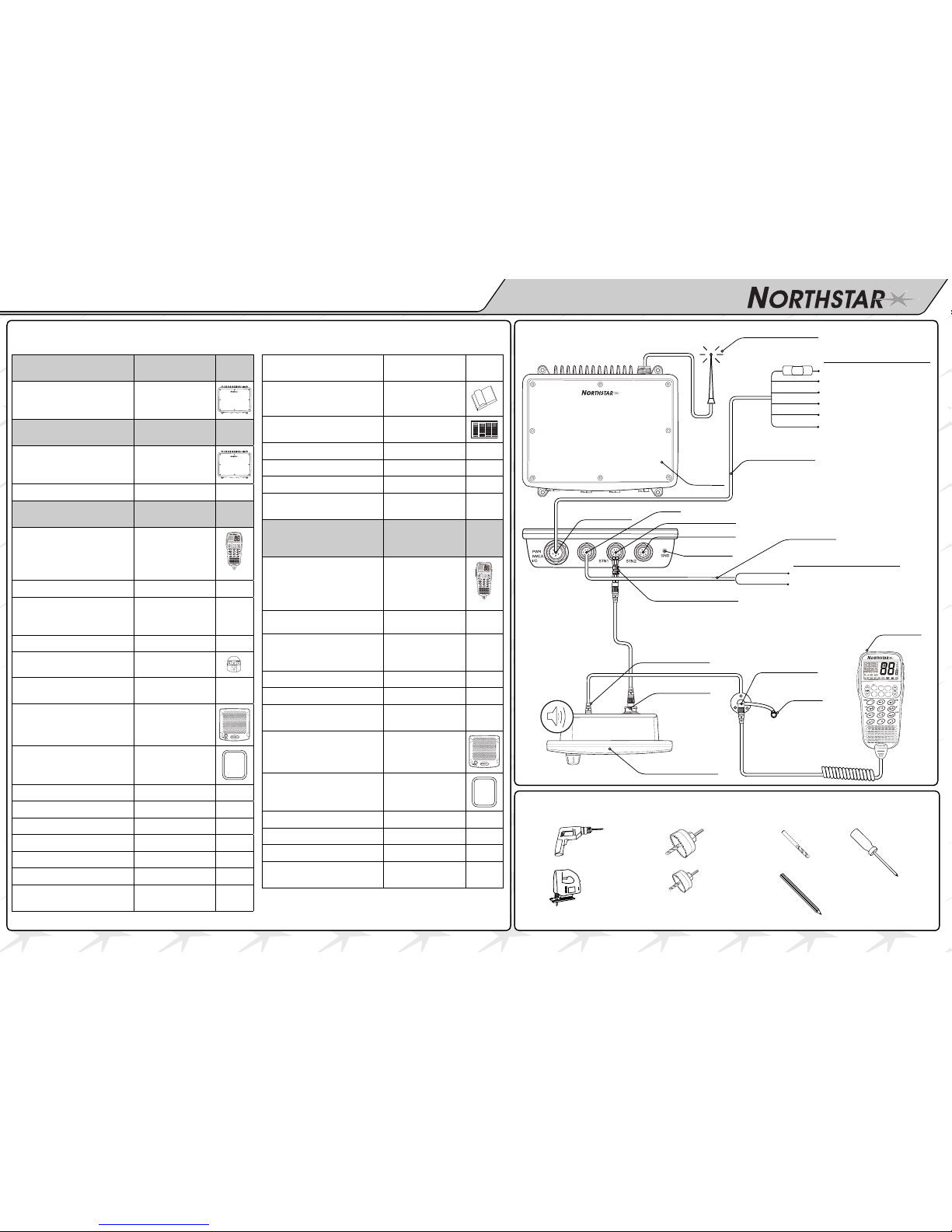
Wiring Setup
3CH
16/9
CALL
SCAN
WX
FUNC
SI NGLE SYSTEM
(NS100SS)
PART CODE
1 x VHF Black Box Radio
(single)
APNSBB2E8070
DUAL SYSTE M
(NS100DS)
PART CODE
1 x VHF Black Box Radio
(dual)
APNSBB2E8080
1 x Hailer Cable
PWNSBB2E7120
ADDITIONAL WITH
EACH SYSTE M
PART CODE
1 x Hand set with cord (US)
APNSBB2E8030
3CH
16/9
CALL
SCAN
WX
FUNC
1 x Mic Plate - black
MMNSBB2E4000
1 x Black Box to Speaker
cord with Female-Female
Adapter
WALI 08L07KX0
WALI08F08F0
3 x SS self tapping screws
MS35-20SPSX1
1 x Mic Clip with magnet
APNSBB2E8050
2 x SS self tapping screws
for mic clip
MS35-20TSPX1
1 x Large Speaker
APNSBB2E8060
1 x Speaker Gasket
MPNSBB2E7040
4 x Speaker tabs
PPNSBB2E3270
4 x SS self tapping screws
MS35-20SPSX1
4 x SS self tapping screws
MS35-20SPSX1
1 x Power Cable w/tags
WALI06LXXXX0
1 x SS Grounding screw
MS30-06PSNX2
1 x Spare 10A fuse
PKFU125V10A0
1 x Mounting Template
- Black Box
PPNSBB2E7080
1 x Mounting Template
- Speaker
PPNSBB2E7030
1 x Quickstart Guide and
Reference Manual
PPNSBB2E7050
1 x Quickstart Guide
PPNSBB2E7070
1 x Radio Installation Sheet
PPNSBB2E7260
1 x Warranty Sheet
PPNSBB2E7100
1 x DSC Sticker
PPNSBB2E7110
1 x Dust Cap for Handset
connector plate
MPLILTD-4/80
OPTIONAL ADDITI ONAL
HANDSET K IT
(NS100HS)
PART CODE
1 x Hand set with cord (US)
APNSBB2E8030
3CH
16/9
CALL
SCAN
WX
FUNC
1 x Mic Plate - black
MMNSBB2E4000
1 x Black Box to Speaker
cord with Female-Female
Adapter
WALI 08L07K X0
WALI 08F0 8F0
3 x SS self tapping screws
MS35-20SPSX1
1 x Mic Clip with magnet
APNSBB2E8050
2 x SS self tapping screws
for mic clip
MS35-20SPSX1
1 x Large Speaker
APNSBB2E8060
1 x Speaker Gasket
MPNSBB2E7040
4 x Speaker tabs
PPNSBB2E3270
4 x SS self tapping screws
MS35-20TSPX1
1 x Installation Sheet
PPNSBB2E7030
1 x Dust Cap for Handset
connector plate
MPLILTD-4/80
Parts Checklist
Tools Required
Antenna
Hand set &
mike clip
Large spea ker
Hand set
connecto r plate
Power/NMEA
10A
10A F us e
HLR
Station 1
Station 2
Ground lug
10 pi n sock et
8 pin socket
COLOR FUNCTION PIN#
RED BATTERY (+) 5
BLACK GR OUND 1
GREEN NME A IN (+) 2
YELLOW NME A IN (–) 6
ORANGE N MEA OUT (+) 3
BLACK N MvEA OUT (–) 4
COLOR FUNCTION PIN#
YELLOW HAILER (+) 1
BLACK HA ILER (–) 8
Black Box
Radio
• Drill
• Sabre saw
•1-1/4” Hole
Saw
•1” Hole Saw
1/8” Drill bit
Phillips
Screwdriver
Pencil
Female-F emale ada pter
Power Cable
Hailer Cable
Dust cap
PPNSBB2E7080 (L A00 040 6A)
Installation Tips Installing Handset Connector Installing Microphone Clip Plate
Installing Remote SpeakerWiring Hailer Connector
Mount the handset near the mounted
connector allowing a drip loop in the MIKE
cord. Be sure there is about 2” of vertical
clearance to allow the handset to be easily
lifted off and returned to the clip plate.
Place the clip plate on the dash with the
magnetic sensor toward the rear. Using the clip
plate as a guide, mark the 2 holes.
Use a 1/8” drill. Mount the clip plate with the 2
screws provided.
Mount the handset connector.
1.
2.
3.
4.
Find a location for the Handset connector near
the vessel steering wheel and check that there is
enough wire length to reach the remote speaker
location. Stretch the mike cord to be sure the
handset is comfortable to use while driving.
Using the black metal plate as a guide, mark the
center of the hole to be drilled.
Use a 1” hole saw to cut out the dash.
Leaving the small rubber gasket on the backside
of the connector, push it through the D hole
in the plate. Put the rubber dust cap over the
connector shaft and tighten the nylon nut.
Hold the plate & connector assembly to the dash
and mark the 3 holes. Use a 1/8” drill. Mount the
plate with the 3 screws provided.
Connect the handset connector.
When removed, be sure to cover the connector
with the provided dust cap.
1.
2.
3.
4.
5.
6.
7.
Check that the location of the powerful 20W
4 Ohm HAILER HORN (not provided) does not
effect the ship’s compass before drilling holes
and mounting. The Horn needs a clear view of
the bow of the boat so the FOG and PA signals
can be heard well by other vessels.
Run 2 #20 AWG wires from the horn to the Box
and connect to the HAILER connector wires.
Follow the wire colors on the front of this sheet
and crimp to the HAILER connector assembly
wiring.
CAUTION
NOTE: DO NOT GROUN D EITHE R SIDE O F THE
HAILER WI RES.
1.
2.
Check the location does not effect the ship’s
compass before drilling any holes.
Using the template provided, use the 1-1/4”
hole saw to cut out the 4 corners.
Use the sabre saw to trim the remaining inside
of the speaker cutout.
Use the 1/8” drill bit for the 4 side mounting
holes.
Mount the speaker with supplied gasket from
the front and hook up the connectors.. No
need to get behind the panel.
Put the 4 speaker clips on the speaker to cover
up the mounting holes for a professional look.
1.
2.
3.
4.
5.
6.
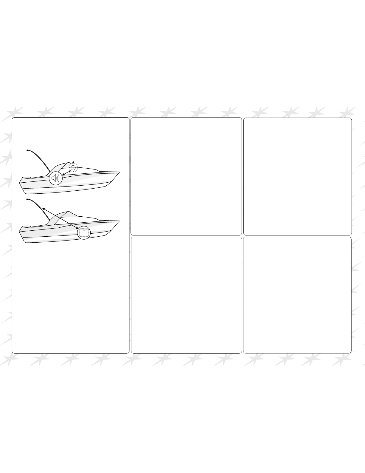
Speaker is at le ast
45cms (1.5') fr om
the compass
Black Box Radio must
be at least 1metre (3’)
from the Antenna
Location Requirements - Please check these before doing
any cutting or drilling.
Ensure that the chosen location:
• is at least one metre (3') from the antenna
• allows easy connection to (at least) a 10 Amp fused 12V
only DC electrical source and the antenna.
• is at least 45cms (1.5') from the compass to avoid
creating magnetic deviation of the compass during radio
operation
• has a suitable space close by for installing the
microphone bulkhead mount
• provides easy access to the front panel controls
• provides reasonable access to the wiring at the back of
the radio.
 Loading...