

North Star MDS-A-O User Manual
NorthSbrCompumlnc
2547 Ninth Street
Berkeley,
Co.
94710
Introduction.
Cautions
Limited
Out
Limited
of
Warranty
Hardware
Software
Software
Parts
List
Assembly
Figure
lA:
Assembly
System
Theory
Integration
of
Appendix
Schematic
MICRO-DISK
DOUBLE
Table
SYSTEM
DENSITY
of
Contents
.....
. . . . . .
Warranty
Repair
. .
Warranty
License
. . . • .
. . . . . . . .
Information
Identification
and
Check-out
• • .
Instructions
. • • • . . . .
Operation
1:
Pulse
Drawings
Signal
• • . • • • . •
MDS-A-D
•
of
Components
•••••
Detection
10
11
22
27
35
36
2
2
3
3
4
4
5
8
,<
l
,
!
I
-~
I
Copyright
1978,
North
star
Computers,
Inc.
MDS-D
REVISION
25010
;
2
The
North
disk
system
includes
regulation,
provided
System,
programs.
drives.
on
a
diskette,
storage.
are
available
If
you
entire
Information
purchased
Assembly
Star
the
on
BASIC
The
Each
Addition
have
manual.
the
section.
Micro-Disk
for
use
disk
cables,
diskette
Language
system
disk
thus
as
options
purchased
Be
section
MDS-A-D
with
controller
software
and
System,
is
drive
allowing
disk
sure
drives,
the
to
before
in
INTRODUCTION
System
5-100
(MDS-A-O)
bus
board,
and
documentation.
includes
capable
can
record
up
MDS-A-D
carefully
beginning
assembled
CAUTIONS
the
Monitor,
of
to
AC
as
computers.
one
floppy
North
and
controlling
179,200
716,800
power
form,
supplies,
a
kit,
read
assembly.
you
is
Star
various
bytes
bytes
then
the
a
complete
The
disk
The
Disk
up
of
of
first
Assembly
If
may
skip
system
drive,
software
Operating
utility
to
four
information
on-line
and
cabinets
skim
you
have
the
floppy
power
disk
disk
the
is
.•
A
.
,
.-
1.
Correct
else.
2.
Do
NOT
while
3.
Do
NOT
turned
4.
Be
sure
correct
5.
Be
careful
correct
6.
Do
NOT
physically
controller
In
7 •
I
,
some
in
the
electrical
drive
drive
this
insert
the
power
insert
on.
the
output
orientation.
connect
cases
vicinity
away
in
a
document
or
is
or
+5
volt
voltages
to
insert
or
tamper
while
disk
of
noise.
from
grounded
the
from
remove
turned
remove
and
all
disconnect,
with
the
power
drives
TV'S,
This
noise
cabinet.
the
Ie's
+12
before
IC's
the
electric
may
the
MDS
on.
from
volt
disk
is
may
be
source
errata
controller
the
regulators
installing
in
correct
mount
drive,
turned
not
operate
motorS,
remedied
or
before
board
or
on.
by
doing
from
while
are
any
positions
dismount,
power
properly
or
by
moving
installing
the
generating
IC·s.
board,
other
anything
computer
the
and
or
in
or
if
sources
the
the
power
with
any
disk
located
disk
disk
is
the
,
•
,
l
way
of
I
I
~.
I
North
star
MICRO-DISK
System
2
-
..
-
'--
..
.
~:;,
....
••
'
'~'North
: ;
parts
{,.
period
.t'
North
;'~-.:
-the
(ixesulting
~~over
~'invalid
.~
documentation
~·<·.·.for
;.
defective
jl~~·exceed
'UNIT
.
:A
·.:units
~·:·costs
'~~
from
tlwarranty
t:-::.
implied,
~!...
product.
~
concerning
.~
North
!::
....
no
.
~
Star
and
of
Star
purchaser.
transportation
warranty
$30
OR
COPY
OF
located
and
the
Star
warranties
Computers,
workmanship
90
Computers,
from
if
all
due
without
PART
THE
arrangements
factory
is
and
No
the
equipment
LIMITED
Inc.
of
days
from
This
improper
Inc.
warranty
to
instructions
are
not
carefully
repair
to
RETURNED
ORIGINAL SALES
outside
made
is
warranty,
completeness,
which
be
purchaser's
purchaser's
FOR
the
are
borne
in
lieu
limited
for
extend
HARDWARE
warrants
this
date
use
the
o"f
will
or
factory.
included
deemed
WARRANTY
United
for
transportation
entirely
of
all
to
the
expressed
any
beyond
the
product
purchase.
repair
does
by
action,
RECEIPT.
correctness,
particular
not
assembly
followed.
North
consent
REPAIR
States
by
other
repai~
or
1mpl1ed,
those
WARRANTY
electrical
to
be
free
If
the
defect
extend
by
purchaser,
Also,
in
Star
then
will
This
the
warranties,
or.
the
the
accompanying
Should
Computers,
a
repair
be
MUST
warranty
of
America
of
customer.
repl~cement
or
application.
expressly
of
such
to
defects
at
defects
warranty
a
assessed.
BE
ACCOMPANIED
the
product
expressed
1S
extended
suitability
stated
and
defects
no
not
unit
charge
applies
only
of
mechanical
for
occur,
cost
does
is
returned
Inc.
This
There
not
ANY
if
to
the
of
herein
to
all
and
or
the
are
a
,'I
to
it
be
to
BY
to
•
,If
your
;diagnosing
'.be
arranged
)computer
<be
shipped
~escription
about
'will
Star.
$25.0~
:amount
description.
unit
technician.
the
problem
be
returned,
Out-of-warranty
per
of
is
or
repairing
with
PREPAID
of
the
hour.
time
out
a
spent
OUT
of
warranty
local
Alternatively,
to
the
problem.
and
about
C.O.D.,
If
you
on
OF
the
dealer
North
within
repair
wish
your
WARRANTY
and
problem,
or
other
Star
Include
your
service
to
unit,
system
30
place
mention
REPAIR
you
are
unsuccessful
out-of-warranty
experienced
any
North
address
as
many
configuration.
days
is
an
after
billed
upper
this
Star
with
details
receipt
at
limit
in
service
local
products
a
clear
as
the
the
at
possible
Your
by
rate
on
written
.,
may
may
written
unit
North
of
the
North
Star
MICRO-DISK
System
LIMITED
SOFTWARE
WARRANTY
"
•
••
f,
The
following
DOS,
DISK SYSTEM.
identical
stored
memory
SYSTEM
If
customer
removed,
it
date
No
completeness,
software
resulting
limited
diskette.
and
on
from
using
a
diskette
is
returned
of
purchase.
warranty,
to
Monitor
to
the
and
then
for
limited
North
the
customer
the
the
malfunctions
has
North
expressed
correctness,
any
from
the
software
North
diskette
North
not
to
North
particular
use
repair
Star
been
Star
of
warranty
delivered
Computers,
star
diskette
by
Star
operated
will
Star,
or
implied,
the
software
or
replacement
applies
master
and
a
properly
disk
and
or
application.
controller
has
re-write
prepaid,
suitability
on
Inc.
copy
can
not
with
is
is
of
to
the
diskette
warrants
of
the
be
read
functioning
been
the
or
replace
within
extended
of
No
covered
the
North
software
board
damaged
write-protect
three
concerning
the
consequential
-
original
Star
with
that
into
MICRO
and
by
the
months
North
this
BASIC,
the
MICRO
a
copy
has
computer
DISK
disk
the
diskette
Star
warranty
software
been
RAM
drive.
tab
if
from
the
damage
is
'~
-1
,.
The
North
North
SYSTEM
Star
under
star
BASIC,
Computers,
the
DOS
Inc.,
following
SOFTWARE
and
and
license
LICENSE
Monitor
are
are
included
agreement:
copyrighted
with
the
products
MICRO
of
DISK
~
~'
lc
.'
,
I
I
I
The
software
HORIZON
customer
as
long
copy.
a
computer
board,
software
Star
disk
computer
may
as
the
This
which
and
also
for
controller
may
make
North
license
use
be
used
and
North
copies
Star
specifically
does
specifically
in
NOT
any
board.
North
in
Star
of
copyright
include
system
Star
conjunction
MICRO DISK
the
software
prohibits
a
prohibits
which
MICRO-DISK
with
notice
North
modification
does
System
SYSTEM
for
is
use
Star
not
the
North
only.
convenience
preserved
of
the
disk
contain
controller
of
Star
The
of
with
software
the
a
North
use,
each
in
;
i
.
""
,
1
4
•

MDS
, ,
..
~
.
9
.'
..
---~---.-
SYSTEM
MDS
CONTROLLER
1
i'!' 5
I
~~
\,~'
1
":
6
"2
1
2
"2
C2
'2
"
:Integrated
PARTS
disk
ribbon
diskette,
diskette,
MDS-D
System
OEM
HDS
MDS
North
printed
20-pin
drive,
Manual
controller
power
16-pin
14-pin
34-pin
crystal,
IN4148
+5
volt
+12
volt
heat
6-32x3/8'·
#6
6-32
sinks,
lock
nuts
Circuits
Shugart
cable
Manual
Software
Star
PARTS
circuit
Ie
Ie
Ie
cable
diodes
regulators,
assembly
blank
pre-recorded
board
name
sockets
sockets
sockets
connector
4MHz
regulator~
6107B-14
machine
washers
PARTS
Manual
with
with
plate
board
Screws
.
SA-4e0
with
parts
parts
(Sit x
header
7805
78L12
LIST
or
(double
software
10"),
340T-S
density)
HDS-AD
",1
.1
.6
'I
2
1
2
1
3
3
1
4
1
74LS00
74LS02
74LS08
74LSIr
74LS14
74LS32
74LS74
74LS109
74LS123
74LS138
74LS161
74LS164
74LSl74
North
Star
3
2
1
1
3
1
3
1
1
1
1
1
1
MICRO-DISK
74LS241
74LS253
74LS257
74LS273
74LS393
7404
7438
74166
DWE
PROM
DSEL
DPGM
LF356
3080
PROM
PROM
System
or
74LS166
(6301
(6301
(63091
or
or
82S129)
82S129)
I
I
I
I
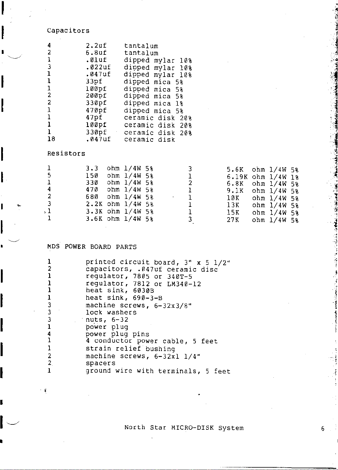
Capacitors
4
I
2
1
3
1
1
1
2
2
1
1
1
1
18
2.2Uf
6.8uf
.01uf
.022uf
.047uf
33pf
100pf
200pf
330pf
470pf
47pf
100pf
330pf
.047uf
tantalum
tantalum
dipped
di?ped
dipped
dipped
dip1?ed
dipped
dipped
dipped
ceramic
ceramic
ceramic
ceramic
mylar
mylar
mylar
mica
mica
mica
mica
mica
disk
disk
disk
disk
10%
10%
10%
5%
5%
5%
1%
5%
20%
20%
20%
I
I
I
I
I
I
I
Resistors
1
I
•
5
1
4
2
3
> 1
1
MDS
1
2
1
1
1
1
3
3
3
1
4
1
1
2
2
1
POWER
3 • 3
150
330
470
680
2.2K
3.3K
3.6K
printed
capacitors,
regulator,
regulator,
heat
heat
machine
lock
nuts,
power
power
4
strain
machine
spacers
ground
ohm
ohm
ohm
ohm
ohm
ohm
ohm
ohm
BOARD
conductor
PARTS
sink,
sink,
washers
6-32
plug
plug
relief
wire
1/4W
1/4W
1/4W
1/4W
1/4W
1/4W
1/4W
1/4W
circuit
.047uf
7805
7812
60308
690-3-8
screws,
pins
power
screws,
with
5%
5%
5%
5%
5%
5%
5%
5%
board,
ceramic
or
340T-S
or
LM340-12
6-32x3/8"
cable,
bushing
6-32xl
terminals,
3
1
2
1
1
1
1
3
3"
x 5 1/2"
5
1/4"
disc
feet
5
feet
5.6K
6.19K
6.8K
9.1K
10K
13K
15K
27K
ohm
ohm
ohm
ohm
ohm
ohm
ohm
ohm
1/4W
1/4W
1/4W
1/4W
1/4W
1/4W
1/4W
1/4W
5%
1%
5%
5%
5%
5%
5%
5%
·
•
-,)
•
•
.;
I
I~
•
North
Star
MICRO-DISK
System
6
.'
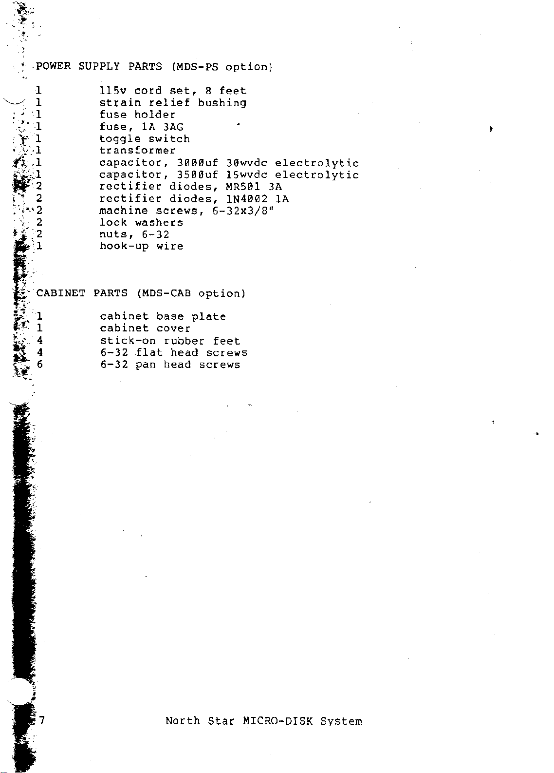
POWER
SUPPLY
PARTS
(MDS-PS
option)
~
:
...
'1
.
-".
v-
r I
,.~"1
({I
W~
i
.~;
~'.~
•.
, 2
".
I
1
-1
2
CABINET
115v
cord
strain
fuse
fuse,
toggle
holder
lA
transformer
capacitor,
capacitor,
rectifier
rectifier
machine
lock
nuts,
hook-up
PARTS
cabinet
cabinet
stick-on
6-32
6-32
washers
6-32
(MDS-CAB
flat
pan
set,
relief
3AG
switch
diodes,
diodes,
screws,
wire
base
cover
rubber
head
head
8
bushing
3000uf
3500uf
option)
plate
screws
screws
feet
30wvdc
15wvdc
MR501
IN4002 lA
6-32x3/8,r
feet
.'
electrolytic
electrolytic
3A
7
North
Star
MICRO-DISK
System
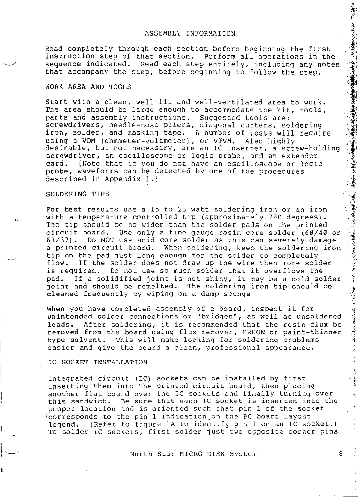
ASSEMBLY
INFORMATION
Read
completely
instruction
sequence
that
WORK
Start
The
parts
screwdrivers,
iron,
using
desirable,
screwdriver,
card.
probe,
described
SOLDERING
Par
with
•
The
circuit
63/37).
a
tip
flow.
is
pad.
joint
cleaned
When
unintended
leads.
removed
type
easier
accompany
AREA
with
area
and
solder,
a YOM
best
a
tip
printed
on
required.
you
solvent.
[Note
waveforms
temperature
the
If
If
and
and
through
step
indicated.
AND
a
should
assembly
of
the
step,
TOOLS
clean,
be
large
instructions.
needle-nose
and masking
(ohmmeter-voltmeter),
but
not
necessary,
an
oscilloscope
that
in
Appendix
TIPS
results
should
board.
Do
NOT
circuit
pad
the
a
solidified
should
frequently
have
solder
After
from
the
give
if
can
use
be
no
Use
use
board.
just
solder
Do
not
be
completed
connections
soldering,
board
This
the
each
that
well-lit
controlled
only
acid
long
remelted.
by
will
board
Read
you
be
1.1
a
15
wider
does
use
joint
wiping
using
section.
before
enough
do
detected
a
core
enough
so
assembly
make
each
pliers,
tape.
not
to
than
fine
When
not
much
it
a
section
step
beginning
and
well-ventilated
to
A number
are
or
logic
have
by
25
watt
tip
the
gauge
solder
soldering,
for
draw
solder
is
not
The
on
a
of
or
"bridges",
is
recommended
flux
looking
clean,
before
Perform
entirely,
accommodate
Suggested
diagonal
all
to
cutters,
of
or
VTVM.
an
Ie
inserter,
probe,
an
oscilloscope
one
of
soldering
(approximately
solder
rosin
as
this
keep
the
solder
up
the
wire
that
shiny,
soldering
damp
a
remover,
professional
sponge
board,
for
it
soldering
beginning
operations
including
follow
the
tools
tests
Also
and
the
procedures
iron
pads
that
FREON
core
can
it
may
iron
inspect
as
on
the
to
then
overflows
well
the
the
area
to
kit,
are:
soldering
will
highly
a
screw-holding
an
extender
or
or
an
700
degrees)
the
printed
solder
severely
soldering
completely
more
be
a
cold
tip
should
it
as
unsoldered
the
rosin
or
paint-thinner
problems
appearance.
first
in
any
notes
step.
work.
tools,
require
logic
iron
(60/40
damage
solder
the
solder
for
flux
the
•
iron
be
or
be
i
.~
f
'.;-;
!
•
.
1'-./
IC
SOCKET
Integrated
inserting
another
this
proper
~corresponds
legend.
To
sandwich.
solder
INSTALLATION
circuit
them
flat
location
to
(Refer
Ie
into
board
Be
and
the
to
sockets,
(IC)
the
over
sure
is
pin
figure
North
sockets
printed
the
that
oriented
1
indication.on
lA
first
Star
can
be
circuit
Ie
sockets
each
to
solder
MICRO-DISK
IC
such
identify
just
installed
board,
and
socket
that
the
two
System
pin
pin
finally
is
1
PC
board
1
opposite
by
then
turning
inserted
of
the
on
an
first
placing
socket
layout
IC
socket.)
corner
into
over
the
pins
8
·
~.'
,
..
".
'f
;:
\.,.
~
.u;;
R"'~
\-
"',
~'.;;
•.
,
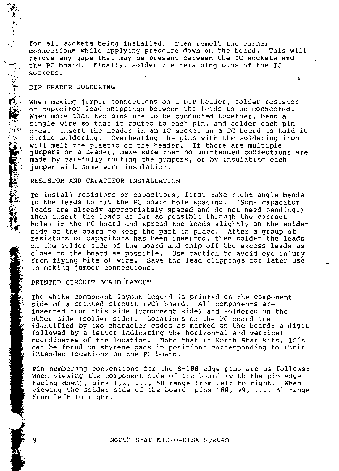
for
all
connections
remove
the
PC
sockets.
DIP
HEADER
When
or
When
making
capacitor
more
single
,once.
during
will
melt
jumpers
made by
jumper
sockets
while
any
gaps
board.
SOLDERING
jumper
lead
than
wire
so
Insert
soldering.
the
on a
header,
carefully
with
some
being
applying
that
Finally,
snippings
two
that
the
header
plastic
wire
installed.
may
be
solder
connections
pins
it
are
routes
in
Overheating
of
the
make
routing
sure
the
insulation.
pressure
present
the
on a DIP
between
to
be
to
an
IC
the
header.
that
jumpers,
Then
down
between
remaining
the
connected
each
pin,
socket
pins
If
no
remelt
on
the
the
the
pins
header,
leads
to
together,
and
on a
with
PC
the
there
unintended
or
by
insulating
corner
board.
IC
sockets
of
solder
be
connected.
solder
board
soldering
are
multiple
connections
the
resistor
bend
each
to
This
IC
hold
each
will
and
a
pin
it
iron
are
RESISTOR
To
install
in
the
leads
Then
holes
side
resistors
on
the
close
from
in
making
PRINTED CIRCUIT
The
white
side
inserted
other
identified
followed
coordinates
can
be
intended
leads
are
insert
in
of
the
solder
to
flying
of
a
side
found
AND
CAPACITOR INSTALLATION
resistors
to
already
the
the
PC
board
or
capacitors
the
board
bits
jumper
component
printed
from
(solder
by.
by
a
of
on
locations
or
fit
the
appropriately
leads
board
side
of
to
of
as
as
and
keep
the
possible.
wire.
connections.
BOARD
LAYOUT
layout
circuit
this
side
side).
two-character
letter
the
indicating
location.
styrene
on
the
capacitors,
PC
board
far
as
spread
the
part
has
been
board
Save
legend
(PC)
board.
(component
Locations
codes
Note
padS
PC
in
board.
first
hole
spaced
possible
the
leads
in
inserted,
and
snip
Use
caution
the
lead
is
printed
side)
on
as
marked
the
horizontal
that
positions
make
spacing.
and
do
through
slightly
place.
then
off
clippings
All
components
and
the
in
North
corresponding
right
(Some
not
After
solder
the
to
avoid
on
the
soldered
PC
board
on
the
and
angle
need
the
correct
on
a
excess
for
component
are
board:
vertical
Star
bends
capacitor
bending.)
the
solder
group
the
of
leads
leads
eye
injury
later
are
on
the
a
kits,
to
their
as
use
digit
IC's
pin
numbering
When
viewing
facing
viewing
from
9
left
down),
the
to
conventions
the
component
pins
solder
right.
North
1,2,
side
...
of
Star
for
the
side
,
the
of
50
board,
MICRO-DISK
8-100
the
range
edge
board
from
pins
System
pins
(with
left
100,
to
99,
are
the
right.
.•.
as
pin
,
follows:
edge
When
51
range
<·========0100MFO)
positive
(+1
lead
\.};...
Axial
ElecHolytic
.
lead
Capacitor
====ODD)====~
Resistor
=
Pin 1
---P"
Resistor
Network
·ii
.1
"
••
Transistor
Regulator
(To-92l
,
Quick-Connect
Lug
and
.047 )
Ceramic
Disc
Capacitor
Ii
I
Dipped
Mylar
Capacitor
'I
I,
I
Dipped
Mica
Capacitor
Regulator
(To-220)
)
+
+
+
-
II~t;"
~
(+l lead
Dipped
Tantalum
Capacitor
,
I
Integrated
Circuit
{Ie}
Figure
IC
Socket
lA.
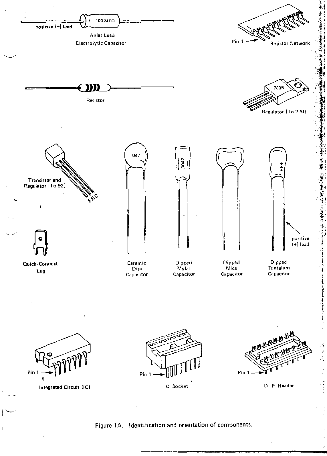
Identification and orientation of components.
DIP
i
l
I
Header
=:
:.f
,
, .
,
, ,
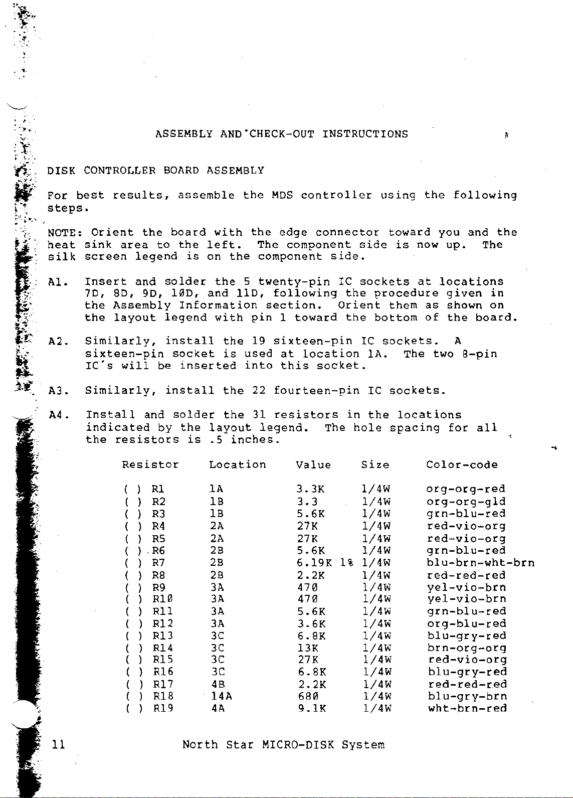
ASSEMBLY
AND'CHECK-OUT
INSTRUCTIONS
ct,
:.'.
~
j,'t
DISK
For
steps.
NOTE:
heat
silk
AL
A2.
'3
n •
A4.
CONTROLLER
best
results,
Orient
sink
screen
Insert
70,
the
the
Similarly,
sixteen-pin
IC's
Similarly,
Install
indicated
the
area
legend
and
80,
Assembly
layout
will
resistors
the
90,
and
BOARD
assemble
board
to
the
is
solder
100,
Information
legend
install
socket
be
inserted
install
solder
by
the
is
ASSEMBLY
the
with
left.
on
the
and
with
layout
.5
the
5
110,
the
is
used
into
the
the
inches.
the
The
component
twenty-pin
pin
19
22
31
legend.
MDS
controller
edge
following
section.
1
sixteen-pin
at
this
fourteen-pin
resistors
connector
component
toward
location
socket.
side.
IC
Orient
The
using
toward
side
sockets
the
the
IC
in
hole
is
procedure
them
bottom
sockets.
lAo The two
IC
sockets.
the
locations
spacing
the
now
at
as
of
following
you
and
up.
locations
given
shown on
the
board.
A
8-pin
for
all
the
The
in
11
Resister
( ) Rl
R2
( )
( )
R3
( )
R4
( ) R5
(
),
R6
( )
R7
( )
RB
( )
R9
( ) RiB
( )
Rll
( )
R12
( ) R13
( ) R14
R15
( )
( )
R16
( ) R17
( ) RiB
( )
R19
North
Location
lA
lB
lB
2A
2A
2B
2B
2B
3A
3A
3A
3A
3C
3C
3C
3C
4B
14A
4A
Star
Value
3.3K
3 • 3
5.6K
27K
27K
5.6K
6.19K
2.2K
47B
47B
5.6K
3.6K
6.BK
13K
27K
6.BK
2.2K
6BB
9.1K
MICRO-DISK
Size
1/4W
1/4W
1/4W
1/4W
1/4W
1/4W
1%
1/4W
1/4W
l!4W
1/4w
1/4W
1/4W
1/4W
1/4W
1/4W
1/4W
1/4W
1/4W
1/4W
System
Color-code
erg-org-red
org-org-gld
grn-blu-red
red-vio-org
red-vio-erg
grn-blu-red
blu-brn-wht-brn
red-red-red
yel-vio-brn
yel-vio-brn
grn-blu-red
org-blu-red
blu-gry-red
brn-org-erg
red-vio-org
blu-gry-red
red-red-red
blu-gry-brn
wht-brn-red
( ) R20
( ) R21
( ) R22
( ) R23
( ) R24
l l
~~~
( 1 R27 12A
( 1 R28 12A
( ) R29
( ) R30 14A
5A
50
6A
60
60
ii~
12A
-J'
1
i
,
-1
10K
470
15K
2.
2K
330
~~~ij~~ ~~~=~~;;=~;~
150
15~
150
150
1/41'1
1/41'1
1/41'1
1/41'1
1/4W
1/41'1
1/41'1
1/41'1
1/41'1
brn-blk-org
yel-vio-brnt
brn-grn-org
red-red-red':
org-org-brn
brn-grn-brn
brn-grn-brn;
brn-grn-brn
brn-grn-brn
,
l
,.;~:
>t<;
J
"
,t~
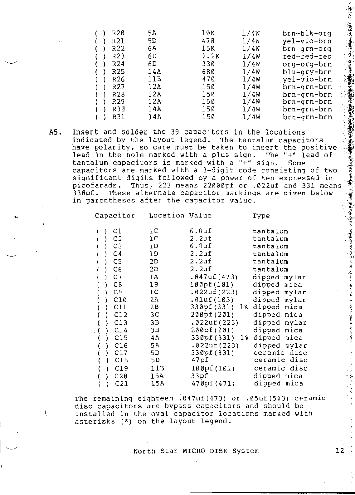
A5.
Inser~
indicated
have
lead
tantalum
capacitors
significant
picofarads.
330pf.
in
The
disc
installed
asterisks
~n:3:o1de/::e
by
the
layout
polarity,
in
the
capacitors
These
parentheses
Capacitor
( )
Cl
( ) C2
( ) C3
( )
C4
( 1
C5
( 1 C6
( )
C7
( ) C8
( 1
C9
( )
C10
( )
Cll
( ) C12
( ) C13
( ) C14
( ) C15
( )
C16
( )
C17
( 1
C18
( ) C19
( )
C20
( )
C21
remaining
capacitors
In
hole
are
digits
Thus,
(*)
so
marked
marked
alternate
after
Location
lC
lC
10
10
20
20
lA
18
lC
2A
28
3C
38
38
4A
5A
50
50
118
15A
15A
eighteen
are
the
oval
on
the
39
care
is
with
followed
223
the
bypass
layout
must
marked
means
capacitor
capa:::ors
legend.
be
taken
with
a
plus
with
a
3-digit
by a
22lHHlpf
capacitor
capacitor
Value
6.8uf
2.2uf
6.8uf
2.2uf
2.2uf
2.2uf
.047uf(473)
100pf(101)
.022uf(2231
.01uf(1031
330pf
200pf(201)
.022uf
200pf(2011
330pf(33111%
.022uf(223)
330pf(331)
47pf
100pf(1011
33pf
470pf(471)
.047uf(473)
capacitors
legend.
The
a "+"
power
markings
value.
(331)
(223)
or
locations
in
1~::
tantalum
to
sign.
code
or
1%
.05uf(5~3)
and
10ca:::::rn-brn,.jj
capacitors
insert
The
sign.
consisting
of
ten
expressed
.022uf
are
Type
tantalum
tantalum
tantalum
tantalum
tantalum
tantalum
dipped
dip?ed
dipped
dipped
dipped
dipped
dipped
dipped
dipped
dipped
ceramic
ceramic
ceramic
diT?ped
dipped
should
marked
the
"+~
Some
and
given
mylar
mica
mylar
mylar
mica
mica
mylar
mica
mica
mylar
disc
disc
disc
mica
mica
ceramic
be
with
positive
lead
of
331
means
below
, ,
I
_~::_:;
of
1;
two
in
~
.1:
-.~:
~;
'
't'
~
J
-a-
,
"
l
•
f
,
"
f
I-
North
Star
MICRO-DISK
System
12
" .
,
~.-
"
..
'to
;-
".,.
n:
~
..
"
.~
,
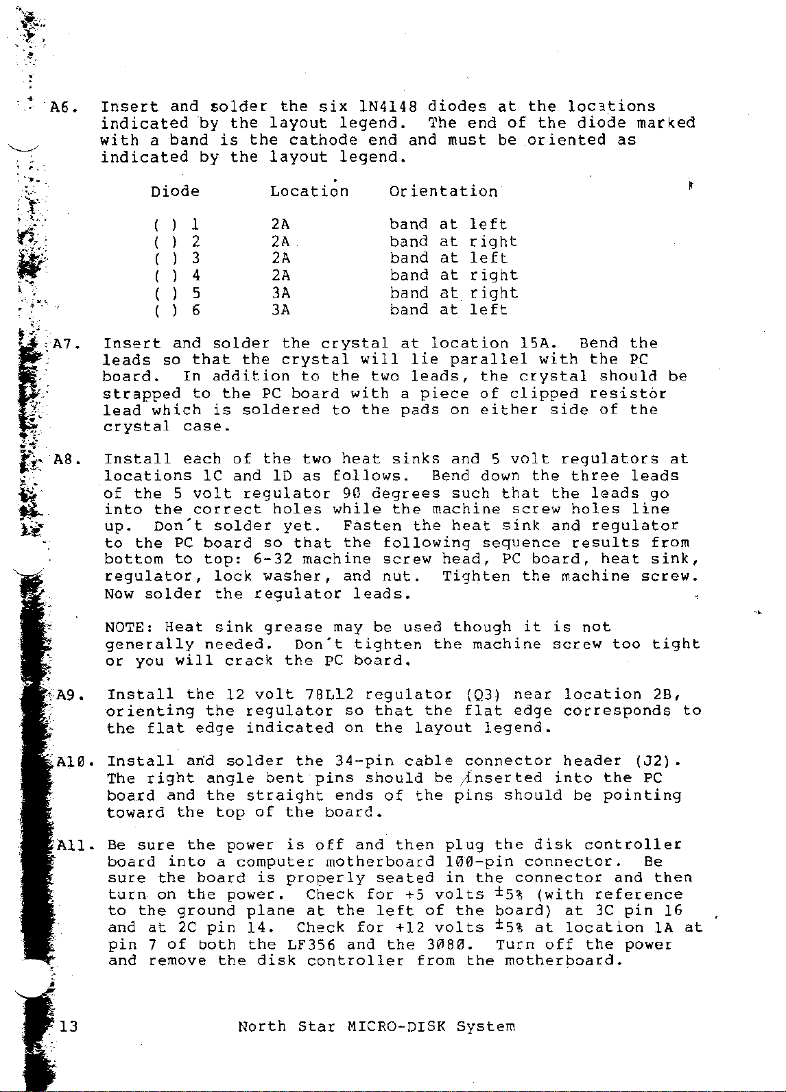
A6.
Insert
indicated
with
indicated
a
Diode
and
band
(
( 2
( 3
( 4
( 5
( 6
-by
by
1
solder
the
is
the
the
layout
the
layout
Location
2A
2A
2A
2A
3A
3A
six
cathode
.
IN4148
legend.
end
legend.
diodes
The
and
must
Orientation
band
band
band
band
band
band
at
at
at
at
at
at
end
left
right
left
right
right
left
at
of
be
the
loc3tions
the
oriented
diode
marked
as
,
,.-.;.-
••
fl:
I
h'
AS.
Insert
leads
board.
strapped
lead
crystal
which
Install
locations
of
the
into
up.
to
bottom
regulator,
Now
NOTE:
generally
or
Install
orienting
the
the
Don't
the
solder
you
flat
and
so
5
PC
to
Heat
will
that
In
to
case.
each
Ie
volt
correct
board
top:
needed.
the
the
edge
solder
the
addition
the
is
soldered
of
and
regulator
solder
6-32
lock
the
regulator
sink
crack
12
volt
regulator
indicated
the
crystal
to
PC
board
the
two
1D
as
holes
yet.
so
that
machine
washer,
grease
Don't
the
crystal
the
to
follows.
while
may
PC
78L12
will
two
with
the
heat
90
degrees
Fasten
the
and
leads.
be
tighten
board.
regulator
so
on
at
lie
leads,
a
piece
pads
sinks
the
the
following
screw
nut.
used
that
the
layout
location
parallel
on
and
Bend
such
machine
heat
head,
Tighten
though
the
the
the
of
either
5
down
that
sink
sequence
PC
machine
(Q3)
flat
legend.
15A.
with
crystal
clipped
side
volt
the
the
screw
and
board,
the
it
is
screw
near
edge
Bend
the
should
the
PC
resistor
of
the
regulators
three
leads
holes
regulator
results
heat
machine
not
too
location
corresponds
be
at
leads
go
line
from
sink,
screw.
-.
tight
28,
to
:A10.
All.
13
Install
The
board
toward
Be
sure
board
sure
turn
to
the
and
pin
and
right
and
the
into
the
on
ground
at
2C
7
of
remove
arid
the
board
the
both
solder
angle
the
top
power
a
power.
pin
the
bent
straight
of
the
is
computer
is
properly
plane
14.
the
LF356
disk
North
the
34-pin
pins
ends
board.
off
motherboard
Check
at
the
Check
controller
Star
cable
should
of
the
and
then
seated
for
+5
left
for
and
MICRO-DISK
+12
the
of
3080.
from
connector
be
4nserted
pins
plug
100-pin
in
volts
the
volts
the
System
should
the
connector.
the
connector
±5%
board)
±5%
Turn
motherboard.
into
disk
(with
at
off
header
the
be
pointing
controller
reference
at
3C
location
the
(J2).
and
pin
power
PC
Be
then
16
IA
at
 Loading...