

Page 1

Northstar 941X
Refe rence Manual
SOFTWARE VERSION 2.05
30 SUDBURY ROAD
ACTON, MASSACHUSETTS 01720
(508) 897-6600
Copyright 1994, 1995, 1996 Northstar Technologies P/N GM1100 Doc. Rev D
Page 2

Page 3

WARRANTY
Northstar Technologies, a Divisi on of CMC E lectr onics, Inc., wa rr ant ees it s pr oducts
to be free from defects in material and workmanship for a period of two (2) years
from the date of shipment to an authorized dealer. This warranty applies to the
original purchaser or subsequent owner.
This warranty covers repair and/or replacement, at our option, of any part or parts
found to be defective, provided such defects in our opinion are due to faulty material
or workmanship and are not caused by tampering, abuse, or normal wear.
All warranties are F.O.B.: Northstar Technologies
30 Sudbury Road
Acton, Massachusetts 01720
This warranty applies only to products in normal use. It does not apply to units or
circuit boards defective due to improper installation, physical damage, tampering,
lightning or other electrical discharge, receivers or ma inframes subjected to fresh
water or saltwater immersion*, units with altered serial numbers, or units repaired
by unauthorized persons or in violation of Northstar service procedures.
The foregoing are the only warranties expressed or implied. No other warranty
exists.
Northstar assumes no responsibility for any conseq uential losses or damages of any
nature with respect to any products or services sold, rendered, or delivered.
*
Certain Northstar control heads are warranty protected against damage due to
water leakage, provided the head has not been tampered with.
Page 4

IMPORTANT NOTICE
Although Northstar products are designed to be very useful navigation tools, they
are not substitutes for good seamanship. T he prudent navigator should never rely on
any single device as the sole source of navigation guidance. Exercise caution and
good judgment whenever underway.
Page 5

!
1
2
C
CONTENTS
ONTENTS
CC
ONTENTSONTENTS
The Northstar 941X
The Northstar 941X
The Northstar 941XThe Northstar 941X
Introduction ................................................................. 2
Upon First Start-up ......................................................2
Using This Manual........................................................3
941X Features...............................................................4
941X Functions............................................................. 5
Comparing GPS and Loran .......................................... 5
Mounting Basics ...........................................................9
Special Functions..........................................................9
The Display Screen.....................................................10
Interfacing Capability..................................................11
Using the Controls
Using the Controls
Using the ControlsUsing the Controls
POWER Key................................................................ 14
CONTRAST Key.......................................................... 14
SAVE/MOB Key...........................................................15
Function Keys.............................................................16
Menu Keys....................................................................17
Cursor Keys..................................................................17
Keypad .........................................................................17
Special Display Windows ........................................... 18
!
3
Basic Navigation
Basic Navigation
Basic NavigationBasic Navigation
Displaying Position, Heading & Speed ......................22
Position Plotter...........................................................22
Using GPS...................................................................25
Using DGPS ................................................................26
Using Loran ................................................................30
Using Phantom Loran ................................................32
Page 6

4
5
Creating Waypoints and
Creating Waypoints and
Creating Waypoints and Creating Waypoints and
Routes
Routes
RoutesRoutes
Entering Data..............................................................36
Creating Waypoints....................................................37
Avoidance Areas .........................................................39
Waypoint Lists............................................................ 41
Coordinate Options ....................................................42
Updating Waypoint Coordinates ...............................42
Editing Waypoints......................................................43
Transferring Waypoints to a PC.................................44
Creating Routes ..........................................................44
Saving a Route ............................................................47
Changing a Route........................................................50
Waypoint & Route Navig
Waypoint & Route Navigaaaation
Waypoint & Route NavigWaypoint & Route Navig
Quick-Start Waypoint.................................................54
Navigating to Waypoints............................................ 55
Navigating Along Routes............................................59
Restarting the Course Line......................................... 61
tion
tiontion
6
The NAV LOG Function
The NAV LOG Function
The NAV LOG FunctionThe NAV LOG Function
What NAVLOG Does ..................................................64
Logging Your Trip.......................................................65
Changing Your Trip ....................................................65
Adding Waypoints to the Trip....................................66
Page 7

7
8
9
Other Special Functions
Other Special Functions
Other Special FunctionsOther Special Functions
Alarms.........................................................................68
Screen Backlighting.....................................................71
TideTrack™..................................................................71
Internal Differential Beacon Receiver ....................... 74
Customizing the 941X
Customizing the 941X
Customizing the 941XCustomizing the 941X
Time of Day.................................................................78
Display Options ..........................................................78
Navigation Options.....................................................82
Receiver Options.........................................................87
Port Setup Options .....................................................90
Service Options........................................................... 91
Geodetic Datum..........................................................94
Installation and Interfacing
Installation and Interfacing
Installation and InterfacingInstallation and Interfacing
Mounting the 941X...................................................100
Wiring the 941X System........................................... 102
Antenna Location .....................................................104
DGPS Antenna Coupler (ACU).................................108
Interfacing the 941X..................................................112
Programming the Output Ports ................................115
Appendix
Appendix (Specifications) ........................................129
AppendixAppendix
Glossary
Glossary..................................................................... 135
GlossaryGlossary
Index
Index .........................................................................138
IndexIndex
Page 8

Figures
Figures
FiguresFigures
Tables
Tables
TablesTables
IGURE
F
F
F
F
F
F
F
F
F
F
F
F
F
T
T
T
T
T
T
T
T
T
1—MAX. P
IGURE
2—Y
IGURE
3—R
IGURE
4—941X GPS-O
IGURE
5—941X C
IGURE
6—S
IGURE
7—F
IGURE
8—C
IGURE
9—ACU A
IGURE
10—PL 259 (UHF) C
IGURE
11—I
IGURE
12—200 PPNM O
IGURE
13—941X D
ABLE
1—D
ABLE
2—I
ABLE
3—P
ABLE
4—NMEA 0183 S
ABLE
5—C
ABLE
6—C
ABLE
7—N
ABLE
8—Y
ABLE
9—C
OSITION VARIANCES WITH UNCORRECTED
OKE MOUNT DRILLING DIMENSIONS
EAR CONNECTORS
OMBO
TRIPPING THE COAX CABLE JACKET
LARED CABLE BRAID
OMPLETED
NTERFACE CONNECTOR (MATING SIDE
ATUM LIST
NTERFACE CONNECTOR PINS
ORT SETUP OPTIONS
ONNECTION TO NORTHSTAR
ONNECTION TO NORTHSTAR
ORTHSTAR
EOMAN ELECTRONIC PLOTTER SETUP WITH
ONNECTING TO EXTERNAL
BNC C
SSEMBLY
IMENSIONS
.....................................................................97
800 S
......................................................103
NLY ANTENNA
GPS/DGPS A
(AN145 & AN150)..........105
NTENNA
..................................................108
ONNECTOR
...........................................................110
ONNECTOR
UTPUT BLOCK DIAGRAM
........................................111
......................................................132
........................................114
.....................................................116
ENTENCE IDENTIFIERS
800 P
800 P
ERIES OUTPUT PORT SETUP
NS B
...........................102
(AN190).............105
............................107
....................................108
)...................... 113
........................115
.............................120
ORT
A.....................123
ORT
B..................... 123
EACON RECEIVER
GPS....8
...............123
941X.......124
......125
Page 9

1
Introducing the Northstar 941X
Introduction 2
Upon First Start-up 2
Using This Manual 3
Features 4
Functions 5
Comparing GPS and Loran 5
Mounting 9
Special Functions 9
The Display Screen 10
Interfacing Capability 11
his section introduces you to the Northstar 941X navigator, outlining its various operational functions, in-
stallation configurations, and specifications.
Use this section to get a quick overview of what the 941X is
all about, and how you can use it to your best advantage.
Rev. D 1 — Introduction
1 — Introduction Page 1
1 — Introduction1 — Introduction
Page 10
Introduction
HE NORTHSTAR 941X combines 12-channel GPS navigation with
T
Differential GPS capability, a high-definition display, loran compatibility, built-in tide data up to the year 2010, and many other navigation
features.
For the ultimate in GPS accuracy, the 941X may be purchased as the
941XD, featuring an internal DGPS (Differential GPS) receiver. This advanced system gives you even greater accuracy by accepting Differential
GPS signal “corrections” from shore-based transmitters (called “beacons”), and using them to display position fixes as accurate as 2-5 meters. You can also connect your 941X to any external source of DGPS
corrections meeting the SC-104 standard (such as the Northstar 8800
DGPS Sensor).
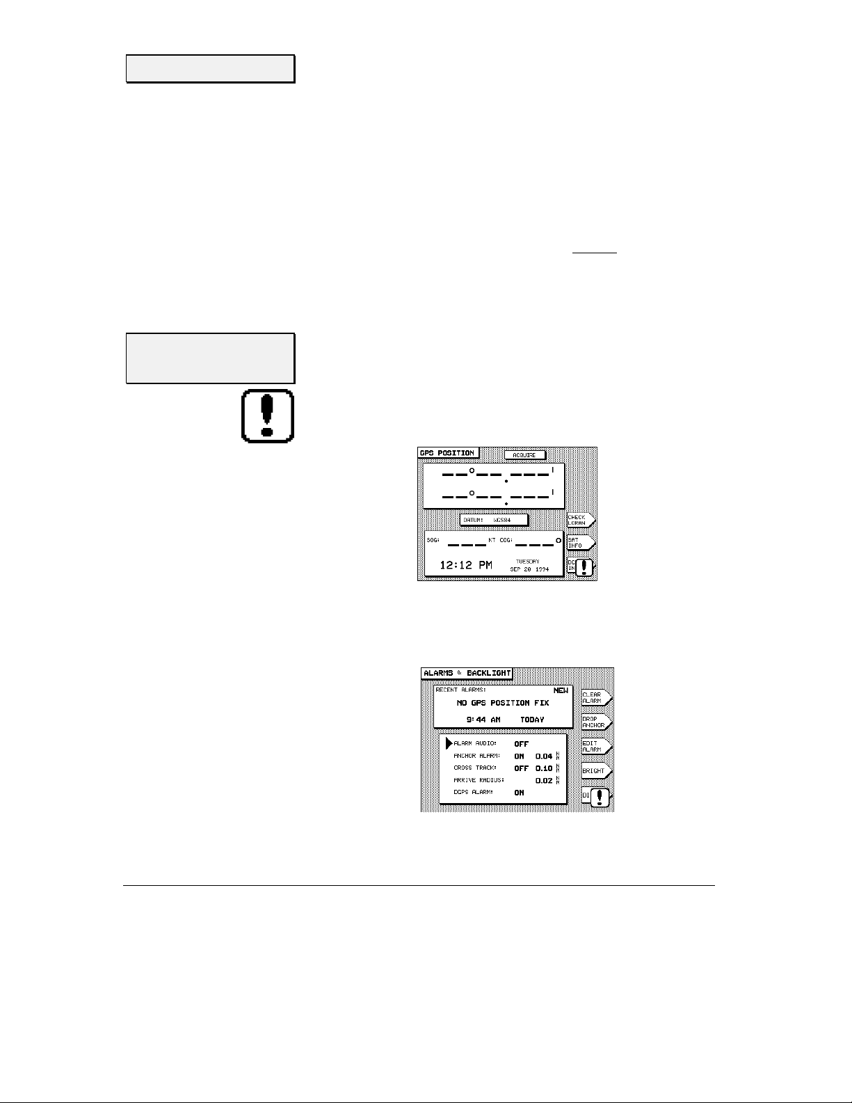
Upon First
Start-up
When you turn your 941X on for the very first time, you may be greeted
with a flashing exclamation poin t symbol in the lower right portion of the
GPS POSITION
the status box at the top. The flashing exclamation point simply means
that an alarm message is present and waiting for your acknowledgment.
To see the message, press the
BACKLIGHT
screen, and the word
screen will be displayed.
ACQUIRE
STAR
key once. The
SKY SEARCH
or
ALARMS AND
in
Page 2 1 — Introduction
1 — Introduction Rev. D
1 — Introduction1 — Introduction
Page 11

The alarm message
date, are shown in the
upper right corner of the box indicates that this is a previously unacknowledged message.
This sequence is a normal part of powering-up the 941X for the first
time, as it notifies you that it is in the process of acquiring satellite information necessary for navigation. It normally takes only two to five
minutes to acquire this data, after which the 941X is ready to navigate.
(This alarm condition usually occurs in units sh ipped to customers located more than several hundred miles from the Northstar factory, and
only the first time the 941X is turned on after being installed.)
NO GPS POSITION FIX
RECEN T ALARM S
box. The word
, along with its time and
NEW
in the
Using This
Manual
"
Press the
acknowledge and clear the message. Press the
left of the screen to return to the main
is now ready to navigate. (For more on alarms, see page 68. If you wish
to proceed directly to navigating with the 941X, skip to page 22.)
Your 941X was designed to be an easy-to-use, full-function GPS navigator, understandable in the information it displays and dependable in its
performance. This Reference Manual is intended to complement that
ease of use by illustrating and describing th e 941X’s various functions in
a format helpful to quick learnin g and safe operation.
The sections in this manual are grouped by relat ed functions, beginning
with an overview of basic control panel layout and function commands,
and gradually progressing to more advanced waypoint and route navigation operations. Sample screen images are used throughout to help illustrate what the 941X displa y screen looks like for the function being
described.
The “helpful hand” (pictured at left) is a convenient shortcut that leads
you directly to step-by-step instructions. You can also use it as a quickreference for locating less-frequently-used operations.
CLEAR ALARM
menu key to the right of the display screen to
POSITION
GPS POSITION
key below the
screen. The 941X
Rev. D 1 — Introduction
1 — Introduction Page 3
1 — Introduction1 — Introduction
Page 12

Features
Upon using the 941X, you’ll see that you can actually learn to operate the
system’s various features without consta nt referral to th is manual. After
you’ve read through it once, you won't have to refer to it very often again .
Since the 941X anticipates your most frequent requests for navigation
information, accessing most functions req uires only one or two button
pushes. By minimizing the attention needed to navigate, you can now
devote more time to other aspects of your trip.
GPS features
navigation
features
waypoints and
routes
• accurate, worldwide position data in any weather, 24 hours a day
• optional internal DGPS (Differential GPS) Beacon Receiver for
accuracy as good as 2-5 meters
• fast signal acquisition
• fast-reacting, accurate speed and course
• lat/lon display
• built-in plotter shows:
1) your position relative to nearby waypoints;
2) your rece nt track line;
3) your intended course line; and
4) avoidance areas,
all against a latitude/longitude grid.
• tide prediction software integrated with navigation display (at
any NOAA tide station; for today or any other date.)
• stores up to 1,000 waypoints and 500 routes
• displays waypoints:
1) in alphabetical order
2) in order of distance from your present position
3) saved with the
4) stored as avoidance points
• plots position of:
1) nearby waypoints
2) routes
3) avoidance areas
SAVE
button
Page 4 1 — Introduction
1 — Introduction Rev. D
1 — Introduction1 — Introduction
Page 13

Functions
Five keys on the 941X instantly select the most commonly used functions, as described below:
POSITION
Speed- and Course-Over-Ground, and Time and Date are also displayed.
An alternate position screen plots your position graphically, along with
any nearby waypoints and your track history.
STEER
waypoint. It also displays your Cross Track Error, Estimated time to
waypoint, Estimated Time of Arrival, Course Over Ground, Speed Over
Ground, Speed of Advance, etc.
(
and accesses setup functions for customizing the operation and displays
of your 941X, including screen brightness.
WAYPTS/ROUTES
navigation.
NAV LOG
trip) and lets you modify it.
displays position coordinates as
1) GPS lat/lon coor dinates
2) loran TDs, if you have a loran receiver interfaced to the unit
3) or calculated “Phantom Loran” TDs if you don't.
shows how to steer precisely along a course line to your current
STAR
) (The
key) displays alarm conditions and tide information,
lets you enter or access waypoints and routes for
displays the progress of your current navigation plan (toda y’s
In addition to these function keys, the
your position as a waypoint, and provides a Man Overboard function for
returning to the saved point.
MENU KEYS
Five
tween specific choices displayed on the screen.
Comparing GPS
and Loran
The nation’s GPS system has received much publicity, often descri bed as
providing the ultimate in navigation accuracy for all applications. Its
major advantage over all other commercially-available navigation systems, including loran, is its all-weather, worldwide availability and
solute accuracy
device to determine your actual latitude and longitude coordinates on
the surface of the earth, as compared to position information determined
Rev. D 1 — Introduction
1 — Introduction Page 5
1 — Introduction1 — Introduction
on the right edge of the display are used to select be-
. (
Absolute accuracy
SAVE/MOB
key instantly saves
ab-
refers to the ability of a navigation
Page 14

from a chart or other r eference.
to return to a position whose coordinates you have previously recorded
with the same equipment.)
Developed by the United States Department of Defense (DOD) the GPS
system of 21 active satellites (with 3 additional spar es) literally encircles
the earth with naviga tion information. GPS is offered in two forms: for
military users and for civil users.
Repeatable accuracy
refers to the ability
selective
availability
GPS and DGPS
With GPS available to virtually anyone around the world, the DOD
wanted to avoid the possibility that its precision could be used by hostile
forces as a source of accurate targeting data against U.S. interests. To
guard against such actions, they introduced intentional errors into the
GPS signals that only U.S. forces could bypass. Called
(or SA), it involves a complex formula of data encryption that can
ability
ability
abilityability
be turned on or off without the end-user ever knowing for sure whether
it is in effect or not. DOD’s stated position is that SA will remain in effect
indefinitely.
Selective Availability effectively reduces GPS’s absolute and repeatable
accuracy from 30 meters (roughly 100 feet) 95 % of the time, to 100 meters (330 feet) 95% of the time. This means that, with SA, you can expect
to be within 300 feet of your intended position 95% of the time, and beyond that area approximately 5% of the time. At first, this was accepted
by most end-users as an inevitable part of GPS, a tradeoff against its
global availability. But it didn’t meet the Coast Guard’s requirement of 820 meter accuracy for navigating harbors. It was then that a system of
differential corrections
them to effectively circumvent SA’s built-in errors.
was developed by the Coast Guard that enabled
Selective Avai
Selective Availlll----
Selective AvaiSelective Avai
These differential corrections are generated by fixed “refer ence stations”
and broadcast by marine radiobeacons over a relatively limited area—
usually a maximum broadcast radius of 250 miles—to Differentialcapable GPS (DGPS) receivers. The precise geographic location of the
reference station is used to calculate corrections based on the GPS data
received from the satellites, and the corrections are then broadcast to
DGPS receivers. The receivers then convert this data into extremely
precise position, heading and speed information. (Referred to as
Page 6 1 — Introduction
1 — Introduction Rev. D
1 — Introduction1 — Introduction
Page 15

“beacons,” the transmitters are being situated at various locations along
the U.S. coastline and Great Lakes, most of which are former marine radiobeacon sites.)
With DGPS, navigators are guar anteed position accur acy on the or der of
2-5 meters
much better). Lat/lon positions displayed to thousandths of minutes
(roughly 6 feet) are common with DGPS. When using a radar or electronic plotter, DGPS corrections improve the steadiness of your displayed plot line dramatically.
In addition to accurate positioning information, DGPS provides critical
“integrity monitoring” of the received GPS signals, enabling the user to
be notified in seconds (as opposed to hours, with uncorrected GPS) that
an anomaly has been detected in a transmitted satellite signal. The integrity monitor instructs the DGPS receiver not to use data from the satellite in question.
50% of the time, and to 10 meters 95% of the time (usually,
loran
Loran, on the other hand, can still outperform non-differential GPS—
when SA is in effect—in
weather and characterized by a relatively limited range (when compared
to GPS), it’s a dependable system familiar to thousands of boat owners.
Since the 1970’s, LORAN users have relied upon that system’s ability to
repeatedly get them back to a previously-saved location with extreme
accuracy. Fishermen especially appreciated this capability because each
subsequent visit to a lobster trap or buoy was virtually “on the mark,”
saving them valuable time and money. Loran’s
superior to anything else commercially-available at the time.
In very good coverage areas, loran can typically get you to within 50 feet
(or roughly 14 meters) of your previously-visited target. On the other
hand, at its very best, uncorrected GPS with SA enabled will get you to
within
300 feet
uncorrected GPS—with variations of up to 300 feet in displayed position—wouldn’t be much help in getting you through a narrow channel.
Since most loran chains were configured for optimum coastline navigation, it’s easy to see why loran’s
masters and fishermen well for the last 25 years.
(100 meters) of your intended destination. Obviously,
repeatable accuracy
repeatable
. Though susceptible to
repeatable
accuracy has served harbor-
accuracy was
Rev. D 1 — Introduction
1 — Introduction Page 7
1 — Introduction1 — Introduction
Page 16

Loran, however, isn’t as proficient as GPS in
absolute accuracy
, or visiting a spot for the first time. Since it transmits at a relatively low frequency (100 kiloHertz—similar to that on your AM radio), your ability to
get an accurate position “fix” is directly related to: 1) your distance from
the loran transmitters, and 2) the weather between you and the transmitters. It’s in these two areas that GPS consistently excels when it
comes to
absolute
accuracy.
Even with SA, GPS provides an
absolute
accuracy of around 300 feet
nearly everywhere in the world, under virtually any conditions. With a
“constellation” of satellites orbiting the earth and transmitting their position data on an extremely high frequency (1.575 GigaHertz, or 1.5
cycles per second), GPS is impervious to weather and your location
lion
bil-
on the surface of the earth. You can receive position fix es at any time,
anywhere, in any weather. This far surpasses the
absolute
accuracy that
is achievable from a good loran receiver in a strong signal coverage area,
in favorable weather conditions: usually 600 feet.
If you are accustomed to using your Northstar loran’s
repeatable
accuracy to return to within a boat length of a lobster trap or a buoy, time after time, you will not necessarily see this same performance with
uncorrected GPS—you could be as much as 600 feet from your expected
position. This will be especially apparent when using the 941X’s plotter
screen (without DGPS), where you may see your boat’s plotted position
appear to wander around within an area up to 600 feet in diameter (see
Figure 1 below).
Position circle of 300-foot radius,
showing possible 600-foot error
between fixes.
ACTUAL
40°00.000 N
72°00.000 W
Figure 1—Max. Position Variances with Uncorrected GPS
Page 8 1 — Introduction
1 — Introduction Rev. D
1 — Introduction1 — Introduction
300’
300’
You could be
anywhere within
the circle, 95% of
the time.
Page 17

getting more
accuracy
If you need a higher level of accuracy than what basic GPS provides,
there are two choices available to you:
Mounting
1. Use
2. Interface your
The 941X is designed to be yoke- or flush-mounted on your boat. The
unit is waterproof and can be exposed directly to the weather. The GPS
antenna should be mounted fairly low on th e vessel to minimize the effects of pitch and roll, and where it has a clear view of the entir e sky. Th e
Beacon Receiver antenna (if installed) should be mounted fairly high,
like a loran antenna. Refer to “Mount ing the 941X,” on page 100, for details.
Differential GPS
beacon receiver (or use an externally-located Northstar differential
beacon receiver), or other source of differential corrections for your
941X. DGPS should provide better than 10-meter accuracy (repeatable and absolute) 95% of the time. See “Using GPS” on page 25 for
more information.
the appropriate NMEA 0183 format output capability). You will
then keep the “repeatable accuracy” of your loran, and add all of
the navigation features of the 941X, including the excellent worldwide “absolute accuracy” of GPS. Refer to Table 2 on pa ge 114 for
connector pin wiring guide.
by installing a Northstar internal differential
loran receiver
to your 941X (provided the loran has
Special
The following functions are unique to the 941X; you may want to read
about them in detail before using them.
Functions
loran TDs
Rev. D 1 — Introduction
The 941X automatically converts GPS coordinates to loran TDs for those
who have lists of fishing spots and other waypoints recorded as TDs. This
feature is called Phantom Loran™. You can display your position as TDs
or enter waypoints as TDs. The accuracy to be expected from this conversion is generally better than 500 to 1500 feet. You can also interface your
existing loran receiver to the 941X and then display and navigate with
1 — Introduction Page 9
1 — Introduction1 — Introduction
Page 18

real-time loran TDs. These features greatly ease the transition from using
loran to using GPS. See page 30 for further details on using loran TDs.
plotter functions
TideTrack™
The Disp lay
Screen
The 941X’s plotter provides a picture of your position, and of what is
around you. Nearby waypoints, avoidance areas, and a lat/lon grid may
be displayed along with an image of your boat.
When you are using the plotter, the five menu keys below the display
screen allow you to perform the following functions:
1) restart the desired track line to run directly from your position to the
waypoint, “zeroing” the cross-track error display
2) change the options available for the plotter
3) center the image of the boat on the screen
4) zoom in to show more detail
5) zoom out to show more area
See page 22 for more information on using the plotter.
TideTrack displays a 24-hour tide graph for any of over 3,000 NOAA tide
stations covering the entire U.S. coast, including Alaska and Hawaii, as
well as much of the western Canadian coastline. Tides may be shown for
today or any other day you ch oose. See page 71 for more information on
using TideTrack.
The Liquid Crystal Display (LCD) and all controls are lighted for nighttime use. The display is easily readable under all conditions, from full
sunlight to total darkness. Anti-ref lection treatment of the display and its
window eliminates over 90% of the reflection and glare. Important data
can be displayed using large numbers which can be seen from a distance.
To adjust the bright ness, press th e
DIM
and
trolled by the
cleaning the
screen
Page 10 1 — Introduction
Use caution when cleaning the plastic window in front of the display
screen. Although it is resistant to scratches, it can be damaged if you
wipe dirt off with a dry cloth. Always use a damp cloth when wiping t he
window. Use a small amount of window cleaner or alcohol to dissolve
menu keys to set the desired illumination. Contrast is con-
ARROW
1 — Introduction Rev. D
1 — Introduction1 — Introduction
key to the left of the screen.
STAR
key (
) and use the
BRIGHT
Page 19

any oil or grease on the screen. Whenever possible, avoid touching the
window with your fingers, as natural oils from your hand will temporarily degrade the characteristics of the window and cause your finger prints
to appear as bright reflections. These will disapp ear when the screen is
cleaned as described above.
CLEANING HINT
CLEANING HINT
Pre-packaged moist towellettes (especially those containing a
small amount of alcohol) are excellent for cleaning t he display
window. You might wish to keep a supply on hand to wipe off
fingerprints and other smudges.
CLEANING HINTCLEANING HINT
Interfacing
Capability
The 941X contains two independent output ports for driving NMEAcompatible devices, two input ports for accepting data from other NMEA
devices, and an auxiliary port reserved for future use. It also features an
RS-232 port for input or output of SC-104 DGPS corrections, and waypoint/route or software program loading from a PC. The 941X can be
interfaced to a wide variety of devices, including autopilots, plotters, radars, etc. Refer to “Interfacing the 941X,” beginning on page 112, for
more information.
Rev. D 1 — Introduction
1 — Introduction Page 11
1 — Introduction1 — Introduction
Page 20

Page 12 1 — Introduction
1 — Introduction Rev. D
1 — Introduction1 — Introduction
Page 21

2
Using the Controls
POWER Key 14
CONTRAST Key 14
SAVE/MOB Key 15
Function Keys 16
Menu Keys 17
Cursor Keys 17
Keypad 17
Special Display Windows 18
HIS SECTION describes each of the Northstar 941X's
controls. Use this section for learning what each con-
trol does and for an overview of usin g its various functions.
Rev. D 2 — Using the Controls
2 — Using the Controls Page 13
2 — Using the Controls2 — Using the Controls
Page 22

HE MAJOR FUNCTIONS of each of the 941X's controls are de-
T
scribed in this section.
POWER Key
Press the
special startup screen that includes an owner-identification message
which you may customize to aid in theft-prevention. Next, the 941X displays the results of the internal self-tests that are automatically run each
time the unit is turned on. Finally, navigation data is displayed.
If any of the six major components of the 941X fails the self-test, the notification
acknowledge it with the press of any function key (located below the display screen). Return the 941X to the factory for service.
POWER
SYSTEM TEST: FAILED
switch briefly to turn on the 941X. The unit displays a
will remain on the screen until you
To turn the 941X off, press the
one full second until the unit turns off.
CONTRAST Key
Page 14 2 — Using the Controls
Liquid Crystal Display (LCD) screens require a contrast adjustment to
compensate for different viewing angles, temperature conditions, etc.
The 941X's contrast control allows you to adjust its display screen to give
the best picture for your current condit ions. Pressing the upper contrast
arrow darkens the screen, and pressing the lower arrow lightens it. Adjust the screen for the best contrast as seen from your normal operating
location.
2 — Using the Controls Rev. D
2 — Using the Controls2 — Using the Controls
POWER
switch and hold it in for at least
Page 23

SAVE/MOB Key
SAVE/MOB
The
It does this in either of two ways, depending on whether you press the
key briefly, or press and hold it.
key is used to save your current position as a waypoint.
saving a
waypoint
Man Overboard
feature
Press the
new waypoint will automatically be given a name, such as –S002–,
where the letter S indicates a saved waypoint, and the 3-digit number
increases by one every time you save a waypoint.
The waypoint’s 3-digit number will “wrap around,” or revert, to –S001–
when the 941X has reached the limit you set using the
WPT #
Press and hold the
Overboard” (MOB) mode. The 941X saves your position and displays it
in the plotter screen as an “X.” The plotter screen is locked on the display, showing your position and the MOB location. The MOB location
immediately becomes your current waypoint, with new bearing and distance information displayed on the right-hand side of the screen.
SAVE/MOB
function under
SAVE/MOB
button briefly to simply stor e your position. Th is
MAX SAVED
DISPLAY OPTIONS
button for three seconds to enter “Man
(see page 80).
INVOKING MOB WHILE USING AN AUTOPILOT
Some autopilots will attempt to steer your boat according to
any bearing changes output by the 941X, regardless of the severity of the change. Others automatically disengage when a
severe or abrupt turn is required. Please refer to your autopilot
manual for information regarding this procedure.
Rev. D 2 — Using the Controls
2 — Using the Controls Page 15
2 — Using the Controls2 — Using the Controls
Page 24

To leave MOB mode and return to normal navigation, press
for at least three seconds.
SAVE/MOB
Function Keys
POSITION key
“Where am I?
STEER k ey
“How do I
get to my
waypoint?”
The five function keys located below th e display screen control wh at the
941X is doing. Any function key may be pressed at any time to display
the information you need to see.
POSITION
The
plotter screen to show your position graphically, relative to nearby waypoints and your track history. Course-Over-Ground and Speed-OverGround are displayed at the bottom of the screens.
Position coordinates may be shown as any of the following:
1) Lat/lon from GPS
2) Lat/lon from an external loran receiver
3) loran TDs from an external loran receiver
4) Phantom Loran TDs which the 941X calculates fr om its GPS coordinates
STEER
The
picture of your position relative to the course line is displayed, along with
all the numeric information you need to steer directly to your waypoint.
Two versions of the steer display are avai lable. Press
the version you were last using. Press it again to see the other version.
key displays your position coordinates, or displays a
key shows how to steer to a waypoint you h ave desi gnat ed. A
STEER
once to see
STAR
STAR key
WAYPTS and
ROUTES key
“Where do I
want to go?”
Page 16 2 — Using the Controls
The
alarms and messages the 941X has waiting for you. The second press
displays information about tides for your choice of over 3000 NOAA tide
stations. The third press displays the time of day, and the time of today’s
sunrise and sunset. The fourth press displa ys a menu of setup and customization functions used whenever you wish to change the way the
941X works for you.
The
access a library of waypoints and routes that you have entered previously, or specify where you want to navigate to.
See Sections 4 and 5 for waypoin t and route information.
key (
WAYPTS/ROUTES
2 — Using the Controls Rev. D
2 — Using the Controls2 — Using the Controls
) has several functions. The first pr ess displays any
key allows you to enter waypoints and routes,
Page 25

NAV LOG key
“How am I
doing?”
NAV LOG
The
you to change those ahead of you. See “What NAV LOG Does,” on p age
64, for more information.
key displays the waypoints you have passed, and allows
Menu Keys
Cursor Keys
Keypad
entering
numbers
The five round
used for different purposes depending on what function is currently being used or displayed. The function of each key is labeled on th e screen,
and pressing the key performs the displayed function.
A large cursor pad in the upper right corner of the 941X allows you to
move the flashing cursor on the display screen to the data you want to
display or change. For example, when entering data (such as a waypoint’s name or coordinates) press the down arrow to move the cursor
downwards to a particular field of data and press the right arrow key to
move the cursor to a particular character in that fiel d.
The 12-button alphanumeric keypad is used for entering numbers, letters
or special characters for waypoint coordinates, names, etc.
When the 941X is expecting you to enter numbers only, such as for waypoint coordinates, the keypad keys enter one digit, 0-9, with each keypress. The flashing cursor moves automatically to the next digit position.
MENU
keys on the right side of the display screen are
For entries such as latitude and longitude—where the digits must be entered into specific characte r positions—the cursor starts on the left side
of the field and characters are entered left to right into their correct positions.
For other numeric entries such as dist ances—wh ere a number of var ia ble
length may be entered—the digits are entered calculator-style from the
Rev. D 2 — Using the Controls
2 — Using the Controls Page 17
2 — Using the Controls2 — Using the Controls
Page 26

right side of the field. If you make a mistake, you can press
clear the entire number and re-enter it, or you can press the left-arr ow
cursor key to reenter particular digits, one at a time.
CLEAR
to
entering letters
"
CLEAR and
ENTER keys
When the 941X is expecting letters to be entered, such as waypoint
names and descriptions, the operation is slightly different. Each key is
labeled with three letters (or other special characters) and a digit.
For example, the upper left key is labeled with the letters A, B, C and the
digit 1. Pressing the key one time displays the letter A. Press the key
again to display the second letter, B. Pressing a third and fourth time
displays the letter C and the digit 1, respectively. A fifth press br ings you
back to the letter A again.
To enter a character, first find the key containing the character, and
press that key one to four times to display the desired character. Finally,
move the cursor to the next character position by pressing the right arrow symbol on the cursor key.
The keypad also contains
ing data that has been typed on the keypad. Pressing the
always the last step when entering or changing data, or acknowledging
an action. The
ENTER
you changed it.
CLEAR
, and sets the field to all blanks or restores it to its value before
CLEAR
key removes any data you typed before you press
and
ENTER
keys for erasing or enter-
ENTER
key is
Special Display
Windows
alarm messages
Page 18 2 — Using the Controls
Occasionally, the 941X needs to inform you of someth ing or ask permission to do something. When this happens, a special information or question window appears on the display. The window contains an
exclamation point (“
and a message for you to read.
Alarm messages contain information you should read right away. Alarms
are communicated by the flashing exclamation symbol in the bottomright portion of the display.
Press the
BACKLIGHT
edge and clear the message.
STAR
2 — Using the Controls Rev. D
2 — Using the Controls2 — Using the Controls
!!!!
”), an “
key once to show the alarm condition on the
screen. Press the
INFO
” label, or a large question m ark (“
CLEAR ALARM
menu key to acknowl-
”),
?
ALARMS &
Page 27

information
windows
Information windows
control functions. They give you extra details pertaining to wha t is about
to happen, or let you acknowledge a command. Information windows
always appear with the word “
are displayed while you are entering data or using
”
INFO
in a small box.
question windows
Rev. D 2 — Using the Controls
Question windows
what you want to do. A question mark will always appear in this type of
window.
You must respond to any question window by pressing
“YES,” or
keys, are inactive when a question window is displayed.
CLEAR
2 — Using the Controls Page 19
2 — Using the Controls2 — Using the Controls
appear when the 941X needs to know more about
to answer “NO.” All other keys, including the function
ENTER
to answer
Page 28

Page 20 2 — Using the Controls
2 — Using the Controls Rev. D
2 — Using the Controls2 — Using the Controls
Page 29

3
Basic Navigation
Displaying Position, Heading & Speed 22
Position Plotter 22
Using GPS 25
Using Loran 30
Using Phantom Loran 32
HIS SECTION describes the most basic—yet important—navigation function available in the Northstar
941X: determining your position.
Position coordinates may be determined from the GPS sat-
ellite system, or you may display loran coordinates if you
have connected a loran receiver.
For those who no longer have a loran r eceiver, but wish to
view their posit ion in loran TDs , the 941 X can conver t GPS
coordinates into Phantom Loran coordinates.
Rev. D 3 — Basic Navigation
3 — Basic Navigation Page 21
3 — Basic Navigation3 — Basic Navigation
Page 30

Displaying
Position,
Heading &
Speed
O DISPLAY the coordinates of your current position, simply press
T
the button marked
position coordinates at the top, and your Course-Over-Ground (COG)
and Speed-Over-Ground (SOG) at the bottom. (If you see the
screen displayed instead of your position coordinates, just press the
POSITION
GPS position coordinates are displayed as latitude and longitude. You
may choose to display loran coordinates instead, as described below.
(Loran coordinates may be obtained fr om a loran receiver connected to
the 941X, or may be calculated by th e 941X from the GPS posit ion coordinates.)
button again).
POSITION
. A screen is displayed showing your
PLOT
Positio n Plo tter
Page 22 3 — Basic Navigation
The position plotter screen is a “ nort h-up ” di spla y, a nd pr ovid es an over all view of the surrounding area and all nearby waypoints. Press the
POSITION
route (if any), your track history, and any nearby waypoints and avoidance points.
A maximum of 30 local waypoints can be displayed on the plotter screen
at one time.
key to show your position plotted relative to your current
3 — Basic Navigation Rev. D
3 — Basic Navigation3 — Basic Navigation
Page 31

The image of your boat displayed on the screen points in the direction of
your Course-Over-Ground. Remember, this direction may be different
from your heading. The boat image shows your actual direction of travel
over the bottom, not the direction your boat is headed. If your boat is not
moving, the Course-Over-Ground cannot be determined by the 941X,
and the direction of the boat on the screen has no meaning.
Avoidance areas (waypoints for which a warning radius has been sp ecified) are shown as a circle surrounding the waypoint.
Your present Speed-Over-Ground (SOG) and Course-Over-Ground
(COG) are displayed at the bottom of the screen, along with the chart
scale. The chart scale is the distance from the top edge to the bottom
edge of the plot.
zooming
centering the
plot
course restart
The plotter screen can be used to steer by when t he object ive is
simply to get to the waypoint without needing to remain precisely on the designated course line.
Press the
the center of the screen. Press the
see more area. Each press of the IN or
doubles the chart scale, respectively.
The maximum zoom-in screen displays an area that is approximately ¼mile from the top edge to the bottom, while maximum zoom-out shows
you an area that is up to 128 miles, top to bottom.
Press the
that your boat is at the center of the screen.
If you wander off your intended course line, and you want to navigate
directly to the waypoint rather than returning to the original course line,
press the
computed and displayed, running from your present position to the next
waypoint.
ZOOM IN
CENTER
RESTART
menu key to zoom in for a closer look at the a rea in
menu key at any time to move the plotted area so
menu key, then
NOTE:
ZOOM OUT
OUT
ENTER
menu key to zoom out to
key approximately halves or
. A new course line will be
Rev. D 3 — Basic Navigation
3 — Basic Navigation Page 23
3 — Basic Navigation3 — Basic Navigation
Page 32

plotter options
To set up the parameters for the display of data on the plotter screen,
press the
The plotter control menu allows you to change the following items:
OPTIONS
• The plotter scale at and above which waypoint names will not be
displayed on the plotter screen
• Whether local waypoints are displayed on the screen
• How often your position is recorded on the screen
• Whether your track history is displayed on the screen
• Whether a lat/lon grid is displayed on the screen
menu key. The following screen is displayed:
"
Page 24 3 — Basic Navigation
To change any one of these, use the up and down cursor keys to move the
arrow to the item you want to change, and press th e
This will cause a large cursor to flash on the field, indicating you should
use the up and down cursor keys to select the option you want. Press
ENTER
The 941X can store up to 900 points in its track, so the maximum length
of the track depends on how often points are stored.
You may choose to store track points every second, with a maximum
length of 15 minutes, or every two minutes for a maximum length of 30
hours, or a number of settings in between.
when done, or
3 — Basic Navigation Rev. D
3 — Basic Navigation3 — Basic Navigation
CLEAR
EDIT
menu key.
to restore the field to its original value.
Page 33

You may also choose to freeze the track, so that no more points will be
stored and the track will remain unchang ed.
Using GPS
lat/lon
coordinates
Pressing the
on the screen.
Press the
Your 941X contains an internal GPS receiver which is used as the primary source of position data.
GPS data is displayed directly on the
The GPS position screen displays your latitude and longitude in large
digits near the top of the screen. If GPS da ta is not ava ilable, dashes a re
displayed in place of the numbers.
CLEAR TRACK
RETURN
menu key to go back to the plotter screen.
menu key clears the track history displayed
GPS POSITION
screen.
You can display lat/lon as either degrees, minutes and seconds,
or as degrees, minutes and thousandths of minutes. See
“Display Options,” on page 78, to select one or the other.
time of day
speed and
course
Rev. D 3 — Basic Navigation
The time of day and today’s day and date (obtained from the GPS satellites) are displayed at the bottom of the screen.
Near the bottom of the screen, your Speed-Over-Ground and CourseOver-Ground are displayed in large digits.
3 — Basic Navigation Page 25
3 — Basic Navigation3 — Basic Navigation
Page 34

The 941X’s speed and course rea dings are t he result of instan taneous measurements derived from satellite signals. GPS
speed is updated every second. However, you may average
these readings by changing the “GPS speed averaging” value
(see page 87).
NOTE
datum
status summary
In the center of the screen, the name of the datum currently in use is displayed. The datum describes the reference of the chart you are currently
using (the reference datum used is indicated on each chart). Applying the
datum corrects for any position differences between your chart and the
GPS coordinate system. See “Geodetic Datum,” on page 94, for more information on selecting the datum for your area.
When using differential GPS (DGPS) as your navigation
source, your position, as displayed by the 941X, may actually
exceed the accuracy of some charts.
NOTE
At the top center of the position screen is a brief status summary of the
GPS receiver. The following table shows the various st atus messages the
941X may display, along with their meanings.
Message Meaning
ACQUIRE
SKY SEARCH
TRACKING
2D NAV
3D NAV
POOR FIX
COMM FAIL
trying to acquire satellites
searching for satellites with no previous information
satellites have been acquired; almost ready to navigate
navigating with 3 satellites in 2-D mode
navigating with 4 or more satellites in 3-D mode
tracking satellites with poor geom etry/accuracy
communication link to GPS sensor has failed—unit
needs repair
Using DGPS
In the upper right corner of the
that shows whether Differential GPS (DGPS) corrections are in use. If
your installation includes an optional Northstar internal differential GPS
receiver, or other external source of differential corrections, navigational
accuracy will be significantly improved when this indicator is present.
Page 26 3 — Basic Navigation
3 — Basic Navigation Rev. D
3 — Basic Navigation3 — Basic Navigation
GPS POSITION
screen is an indicator
Page 35

For further information on operating in DGPS mode, refer to “Internal
Differential Beacon Receiver,” on page 74.
With DGPS active, you will often see position measurements accurate to
about 2-5 meters, speed measurements accurate to about 0.1 knot, and
Course-Over-Ground measurements accurate to about 0.5 degree. DGPS
corrections remove the errors caused by Selective Availability (SA) and
the atmosphere, and provide an accuracy exceeding that obtained by
military users of the GPS system. If the DGPS indicator is displayed, you
have this higher level of accuracy. For the
POSITION
and
STEERING
screens, the DGPS indicator is a large letter “D.” For the plotter screen,
the DGPS indicator is the symbol
DGPS
.
satellite status
To display more information about signa ls received from the GPS satellites, press the
SATS
menu key on the GPS position screen. A screen is
displayed showing the received Signal-to-Noise Ratio for each satellite,
and a map indicating where the satellites are currently located in the sky
(the 12-channel
are identified by their
GPS SATS
PRN
U.S. government.
The center of the satellite map represents the center of the sky, and the
outer (or last) ring is the hor izon. The view is looking down from above,
with East to your right and West to your left.
Rev. D 3 — Basic Navigation
3 — Basic Navigation Page 27
3 — Basic Navigation3 — Basic Navigation
screen is shown on the next page). Satellites
number, a two-digit number assigned by the
Page 36

On five-channel 941Xs, the last bar at the bottom of the screen
will sometimes “jump” around once per second as the 941X
receiver sequen ces among other satellites.
NOTE
The following GPS data is also displayed:
ACCURACY
ACCURACY: The estimated accuracy of the GPS system to be
ACCURACYACCURACY
expected at the current time. Your position readings should be more accurate than this estimate 95% of the time.
HDOP
HDOP: This is a technical measure of the “quality” of your fix.
HDOPHDOP
HDOP (Horizontal Dilution of Precision) ca n range from an idea l value
of 1, up to 10 or more. Any value less than 2 indicates excellent performance. HDOP is calculated from the satellites’ current positions, and is not
based on actual received signals. You will usually see an HDOP value
displayed immediately after the unit is turned on, and before it is ready
to navigate.
RETURN
DGPS
menu key to return to the previous screen.
menu key on the GPS position screen. A screen is
DGPS status
Press the
To display more information about DGPS corrections that are being received, press the
displayed showing the DGPS beacon transmitter currently in use. The
upper part of the screen shows the beac on’s name and position, the frequency of the transmitter, and the baud rate of the transmitted data.
Page 28 3 — Basic Navigation
3 — Basic Navigation Rev. D
3 — Basic Navigation3 — Basic Navigation
Page 37

The lower part of the screen shows three bar graphs:
1. SNR
SNR The Signal to Noise Ratio (SNR) is a good overall mea sure of
SNRSNR
overall signal quality, and should be as high as possible. Values of
15 and higher are preferred, while anything below 10 could indicate
poor reception.
2. SIGNAL
SIGNAL The actual strength of the received signal—should be as
SIGNALSIGNAL
high as possible. Varies with distance from beacon transmitter.
3. NOISE
NOISE Noise level measures the “static” caused by lightning and
NOISENOISE
other atmospheric effects, a nd should be low for best results. See
“DGPS antenna mounting” on page 112, for further details.
NOISE LEVEL VALUE MEANING
200 or less excellent
1,000 – 3,000 typical at night
5,000 – 10,000 thunderstorm
At the bottom of the screen a summary of DGPS operation is displayed.
You may see one of the following messages:
Rev. D 3 — Basic Navigation
3 — Basic Navigation Page 29
3 — Basic Navigation3 — Basic Navigation
Page 38

MESSAGE MEANING
OLD CORRECTIONS
NOT INSTALLED
UNHEALTHY
BEACON
UNHEALTHY SATS
ACQUIRING SATS
DGPS IN USE/ OK
DGPS signal quality information for the 941X is available from the optional internal beacon receiver, or from an opti onal external Northstar
beacon receiver. Other brands of beacon receivers may supply DGPS corrections but omit the additional signal information shown on the 941X’s
screen.
No DGPS corrections have been received
within the
RECEIVER OPTIONS
in
ute), and the navigator has returned to nondifferential operation. See “GPS data timeout” on page 89 for details.
A beacon receiver is not installed.
The beacon transmitter reports it has problems.
Data received from satellites cannot be relied upon.
1) The GPS receiver cannot operate in
DGPS mode until it has received ephemeris
data from the satellites; or 2) the receiver
does not have a GPS fix yet.
DGPS corrections are being received and
used.
DGPS DATA TIM EO UT
(default is 1 min-
limit set
Using Loran
selecting loran
"
Press the
If you have a loran receiver connected to your 941X, you can navigate
using loran coordinates as well as GP S. Just select lor an as t he source of
navigation data, as described below, and you’re on your way.
To display loran TD coordinates from a loran receiver interfaced to the
941X, first select loran as the navigation source, as described below.
1. Press the
2. Press the
3. Press the
RETURN
displayed.
SOURCE
menu key to return to the previous screen.
STAR
key until the
NAVIGATION OPTIONS
line will be designated by the cursor arrow.
EDIT
menu key. The cursor will begin flashing.
USER CU STOMIZATION
menu key. The
screen is
NAVIGATION
Page 30 3 — Basic Navigation
3 — Basic Navigation Rev. D
3 — Basic Navigation3 — Basic Navigation
Page 39

4. Press the up and down cursor arrow keys to display
LRN
as the position source. If you change your mind, press
to restore the original setting; otherwise, press
RETURN
menu key.
ENTER,
EXTERNAL
CLEAR
then the
loran TDs
The loran display screen looks like this:
Press the
pair of TDs you wish to use, or the loran-derived latitude/longitude.
L/L TDS
In order to display loran position coordinates on the 941X
from an externally-connected loran receiver, the loran must
support the standard NMEA 018 3 “RMA” output data sentence
structure. Without this output capability, the 941X will not receive position data from the loran. For best results, connect a
Northstar 800 series loran to the 941X, using the 800’s
“PRINTER 3” output format. See “connecting to a Northstar
800 series loran” on page 123.
menu key several times to select either the p arti cular
NOTE
loran GRI
loran warnings
Rev. D 3 — Basic Navigation
The four-digit loran Group Repetition Interval (GRI) is changed using
SET GRI
the
this to correctly match the GRI being used by your loran receiver for the
941X to accurately convert the loran’s TDs to latitude/longitude position
fixes.
Loran warning indicators obtained from any Northstar 800 series loran
receiver are displayed to the right of each TD. These are:
menu key on the
3 — Basic Navigation Page 31
3 — Basic Navigation3 — Basic Navigation
LORAN POSITION
screen. You must set
Page 40

INDICATOR MEANING
SNR
BLNK
CYC
LOCK
Note: These indicators are available only from Northstar 800 lorans.
The “L/L” indicator to the left of a TD designates it as one of the two TDs
that the loran receiver has chosen to use to calculate latitude and longitude.
The “F/L” indicator to the left of a TD indicates that it has been forced by
the user to be used to calculate lat/lon.
Signal-to-Noise Ratio is low—use caution
Coast Guard is transmitting a blink signal indicat-
ing a probable transmitter problem
the receiver has detected a possible cycle slip
the receiver has locked onto the loran track point.
This is not a warning indicator but an indication of
normal performance.
loran info
checking GPS
status
returning to GPS
navigation
Using Phantom
Loran
Phantom Loran
operation
To check the quality of signals being received by your loran, press the
LORAN INFO
nal-to-Noise Ratio for each loran transmitting station is displayed
graphically. Press
To temporarily display GPS coordinates and signal status, press the
CHECK GPS
will display loran data the next time you return to the position screen.
To return to GPS signals for naviga tion, r ep eat th e step s sh own ab ove for
selecting loran, except specify GPS instead of loran.
The 941X’s Phantom Loran feature is designed for th ose users who have
compiled lists of fishing spots or oth er locations as loran TDs, and are
now using the 941X as a GPS-only navigator. The 941X will mathematically convert GPS lat/lon coordinates to loran TDs, enabling y ou to display your position as TDs.
The 941X may be used to simulate full operation of a loran receiver. Position coordinates may be displayed as TDs, and all navigation functions
may be used as if the unit were actually receiving loran signals. Remem
menu key from the
RETURN
menu key. The unit continues to navigate using loran, and
to go back to the loran position screen.
LORAN POSITION
screen. The Sig-
Page 32 3 — Basic Navigation
3 — Basic Navigation Rev. D
3 — Basic Navigation3 — Basic Navigation
Page 41

ber, however, that these calculated TDs will not match exactly the positions of previously recorded TD coordinates obtained directly from actual loran signals. In most areas, errors should not exceed 0.2
microsecond. However, larger errors are possible in areas for which the
941X does not contain accurate, factory-programmed ASF correction
points.
selecting
Phantom Loran
"
Phantom Loran
TDs
To display Phantom Loran TDs as position coordinates, first select
Phantom Loran as the position source, as described below.
1. Press the
displayed.
2. Press the
GATION SOURCE
3. Press the
4. Press the up or down arrow keys to display
position source.
5. Press
6. To view your position in Phantom Loran coordinates, press
POSITION
The Phantom Loran display screen looks like this:
STAR
key until the
NAVIGATION OPTIONS
line will be designated.
EDIT
menu key.
ENTER
, then the
.
USER CU STOMIZATION
menu key.
RETURN
menu key.
screen is
THE NAVI-
PHANTOM LRN
as the
Rev. D 3 — Basic Navigation
3 — Basic Navigation Page 33
3 — Basic Navigation3 — Basic Navigation
Page 42

choosing L/L or
TDs
Press the
TDs you wish to use or to display GPS latitude/longitude.
L/L TDS
menu key several times to select the particular pair of
Phantom Loran
GRI
checking GPS
status
checking DGPS
status
DGPS
corrections
returning to GPS
navigation
Press the
the displayed TDs. Press the up and down cursor keys to display the
available GRIs one at a time. When the GRI is correct, press
Press the
status, as described on page 27.
Press the
beacon receiver, including SNR, SIGNAL and NOISE values (as previously described on page 29). Press
the
The large letter displayed in the upper right corner of
the display indicates differential GPS corrections are being received and
used to improve the accuracy of the received data.
To return to GPS signals for naviga tion, r ep eat th e step s sh own ab ove for
selecting loran, except specify
See “Navigating to Waypoints,” beginning on page 55, to learn how to
navigate to loran, Phantom loran, or GPS coordinates.
SET GRI
SAT INFO
DGPS INFO
PHANTOM LORAN
menu key to change the GRI to be used in calculating
menu key to check on the received GPS satellite
ENTER
menu button to display the current status of the
RETURN
position screen.
GPS
instead of Phantom Loran.
when you wish to go back to
.
Page 34 3 — Basic Navigation
3 — Basic Navigation Rev. D
3 — Basic Navigation3 — Basic Navigation
Page 43

4
Creating Waypoints and
Routes
Entering Data 36
Creating Waypoints 37
Avoidance Areas 39
Waypoint Lists 41
Coordinate Options 42
Updating Waypoint Coordinates 42
Editing Waypoints 43
Transferring Waypoints to a PC 44
Creating Routes 44
Saving a Route 47
Changing a Route 50
In this section, we’ll learn how to create waypoints, use
them to form routes, and change them as necessary.
Rev. D 4 — Creating Waypoints and Routes
4 — Creating Waypo ints and Routes Page 35
4 — Creating Waypoints and Routes4 — Creating Waypoints and Routes
Page 44

Entering Data
"
Before we move on to the sections describing how to enter waypoints and
routes into the 941X’s memory, let’s take a break and review the methods
for entering data into the unit.
Some screens, such as coordinate entry screens, allow entry of numbers
only. Others, such as waypoint names, allow entry of letters, d igits and
punctuation characters.
A typical entry screen will have several items of data displayed. First,
choose the item you wish to change by pressing the up or down cursor
arrow key to move the flashing cursor to that item.
The flashing cursor indicates which character position will be written
into. Use the left and right cursor arrows to move the flashing cursor to
the next character you want to enter.
Use the up and down arrows to move to the next line you want to enter.
entering
numbers
entering letters
When the entire screen is correct, press th e
accept the full screen of data and store it in memory.
To enter numbers, simply press the digits of the keypad. The flashing
cursor automatically moves to the next character.
You can use the arrow keys to “back up” and correct any mistakes you might have made.
Many items, such as waypoint names, accept letters as well as numbers.
Each key of the keypad is labeled with up to four characters. Find the key
with the desired character, and press that key one or more times to display the character. When the char acter has been selected, use the right
arrow cursor key to move the cursor to the next character position. Press
ENTER
Here are some of the things you can do with waypoints using your 941X:
when all the characters are correct.
1. Navigate to a point in one step (a “quick start” waypoint)
2. Enter waypoints into the 941X’s memory for later use
3. Navigate to these waypoints
ENTER
key. The 941X will
Page 36 4 — Creating Waypoints and Routes
4 — Creating Waypoints and Routes Rev. D
4 — Creating Waypoints and Routes4 — Creating Waypoints and Routes
Page 45

4. String these waypoints together to form routes
5. Follow these routes
6. Edit or erase waypoints or routes
7. Plot waypoints or routes
8. Transfer waypoints and routes from the 941X to a personal computer, and back again.
Creating
Waypoints
To enter waypoints, press the
WAYPT LI ST
to the following is displayed:
To store a waypoint permanently in the 941X's memory, first assign it a
name. The name can be from 1 to 6 characters long, and it must differ by
at least one character from any other waypoint name in the unit's memory.
Enter the desired waypoint name. If you wish, you may also enter up to
16 characters of descriptive information for the waypoint on the line below the name (the description is optional).
menu key and then the
WAYPTS/ROUTES
ADD
menu key. A screen similar
key. Press the
If the name you chose is already in use in t he unit’s m emory, a
message is displayed, indicating you cannot use that name.
You can either erase the old waypoint, i f it i s no longer n eeded,
or choose a different name for the new waypoint. The name of
the new waypoint need only be different from the existing
waypoint by one character in order to be accepted as a valid
name.
Rev. D 4 — Creating Waypoints and Routes
4 — Creating Waypo ints and Routes Page 37
4 — Creating Waypoints and Routes4 — Creating Waypoints and Routes
Page 46

waypoint
coordinates
"
Waypoint coordinates can be entered as lat /lon coordinates, loran TDs,
or as distance and bearing from your present locat ion or from any waypoint in the 941X’s memory.
To change the coordinate type from what is currently displayed, press
COORD TYPE
the
Enter the waypoint coordinates as previously described on page 36. If
you make a mistake, press
start over; otherwise, press
If you are entering coordinates as distance and bearing, the 941X normally asks for these coordinates relative to your current position, known
HERE
as “–
–.”
menu key until you see the option you want.
CLR
to erase any characters from the line and
ENTER
when the screen is correct.
To select an entirely different location from which distance and bearing
are to be measured, such as an existing waypoint, p ress th e
key. A waypoint list is displayed. You can press the
COORD OPTION
Use the up and down cursor arrow keys to point to the desired waypoint.
Press the
ous screen. If you wish instead to use your present position as the reference point, press the
POSITION
Page 38 4 — Creating Waypoints and Routes
ENTER
screen.
4 — Creating Waypoints and Routes Rev. D
4 — Creating Waypoints and Routes4 — Creating Waypoints and Routes
menu keys to help select the waypoint.
key to designate this waypoint and return to the previ-
FROM ‘HERE’
FROM
NEXT LIST
menu key on the
menu
or
‘FROM’
Page 47

avoidance area
If this new waypoint is to be used as the center of an
ter the warning radius at the bottom of the screen in the
box. If no radius is entered, the point will be treated as a regular waypoint, and not as an avoidance area.
avoidance area
WARN RADIUS
, en-
Avoidance
Areas
You may designate new or existing waypoints as avoidance ar eas. Avoidance areas are depicted on the
around them. In addition, an alarm will be given both as an audio beep
and a flashing exclamation point on the screen, if you should enter and
avoidance area.
The 941X will display each avoidance area as a circle the size of the
warning radius you entered. For new waypoints, enter a distance in the
WARN RADIUS
isting waypoints, use the
point coordinate screen, then enter the warning radius. Be sure to
include a little extra distance around the hazard so that you will have
time to respond by turning or stopping after you hear the alarm.
box at the bottom of the
PLOT
screen as waypoints with circles
EDIT WAYPOINT
NEW WAY PT
function to access the way-
screen. For ex-
Rev. D 4 — Creating Waypoints and Routes
4 — Creating Waypo ints and Routes Page 39
4 — Creating Waypoints and Routes4 — Creating Waypoints and Routes
Page 48

As a precaution, once you have designated a waypoint as an avoidance
area, the 941X does not allow you to navigate to it.
avoidance area
alarm
"
Once you have designated a waypoint as an avoidance area, the 941X will
alert you upon penetration of that are a.
To set the audible avoidance area alert feature:
1. Press the
screen.
2. Be sure that the cursor arrow is in front of the
option.
3. Press the
4. Use the up/down cursor keys to toggle the setting ON or OFF.
5. Press
changed.
(NOTE: If you do not want to be notified of any other navigational
alarms, set the
DGPS
and
enter an avoidance area.)
The 941X’s avoidance alarm is intended only as an extra added
safety feature to help make you aware of possible hazards. It
does not replace local knowledge, prop er us e of cha rt s, t he p erson on watch, or any other aspects of good seamanship that are
required for safe navigation.
STAR
key once to display the
EDIT ALARM
ENTER
alarms to OFF. The audible alert will now only beep when you
to make your selection, or
ANCHOR DRAG, CROSS TRACK, ARRIVE RADIUS
menu key.
CAUTION:
ALARMS & BACKLIGH T
ALARM AUDIO
CLEAR
to leave it un-
,
Page 40 4 — Creating Waypoints and Routes
4 — Creating Waypoints and Routes Rev. D
4 — Creating Waypoints and Routes4 — Creating Waypoints and Routes
Page 49

Waypoint Lists
Waypoints contained in your 941X can be displayed in any of four ways.
Press the
WAYPTS/ROUTES
function key, then the
menu key to display waypoint lists. Use the
NEXT LIST
WAYPT LIST
menu key to se-
lect the list that is best for your current situation. Each press of the
NEXT LIST
ALPHA, SAVED, AVOID
ALPHA
ALPHA list: all waypoints in alph
ALPHAALPHA
menu key displays a waypoint list in the following order:
LOCAL
and
list: all waypoints in alphaaaa----
list: all waypoints in alph list: all waypoints in alph
betical order
betical order
betical orderbetical order
, then starting again at
SAVED
SAVED list: all waypoints
list: all waypoints
SAVEDSAVED
list: all waypoints list: all waypoints
created via SAVE/MOB
created via SAVE/MOB key,
created via SAVE/MOBcreated via SAVE/MOB
with most r
with most reeeecent first.
with most rwith most r
ALPHA
cent first.
cent first.cent first.
key,
key, key,
.
AVOID
AVOID list: Avoidance waypoints within 100
list: Avoidance waypoints within 100
AVOIDAVOID
list: Avoidance waypoints within 100 list: Avoidance waypoints within 100
nm,
nm,
nm,nm,
nearest first
nearest first
nearest firstnearest first
alpha list
Waypoints listed under the
ALPHA
displayed in alphabetical order. Waypoints with a digit as the first character appear near the beginning of the list. “Saved” waypoints appear
near the end.
Rev. D 4 — Creating Waypoints and Routes
4 — Creating Waypoint s and Routes Page 41
4 — Creating Waypoints and Routes4 — Creating Waypoints and Routes
LOCAL
LOCAL list: 30 closest waypoints within
list: 30 closest waypoints within
LOCAL LOCAL
list: 30 closest waypoints within list: 30 closest waypoints within
100 nm,
100 nm,
100 nm,100 nm,
nearest first
nearest first
nearest firstnearest first
screen in the 941X’s memory are
Page 50

saved list
All saved waypoints (stored by pressing the
having a name such as –S001–) are listed in order of the time at which
they were saved, with the most recent first.
SAVE/MOB
button, and
avoid list
local list
Coordinate
Options
Up to 30 avoidance points within 100 nautical miles are listed in order of
their distance from your position.
LOCAL
In the
miles are listed in order of distance from your p osition. This list is particularly useful when you wish to deal with only the wa ypoints in your
area. Even though you may have hundreds of waypoints stor ed, the local
waypoints are very often the only ones you are interested in. You may
find yourself using this list most of the time.
Whenever a waypoint list is displayed, you may display the waypoint’s
coordinates on the right side of t he screen in any of t he following ways,
by pressing the
1. latitude/longitude coordinates
2. coordinates originally used to save the waypoint (TDs, lat/lon)
3. distance and bearing from your position (this is often the most
useful way, since it may be easier to visualize “3 miles north” than
the digits of lat/lon coordinates).
The letter “S” to the right of the waypoint name indicates that the displayed coordinates were the ones used to store the waypoint (TDs vs.
lat/lon).
list, up to 30 of the closest waypoint s within 100 nautic al
COORD OPTION
menu key:
Updating
Waypoint
Coordinates
Page 42 4 — Creating Waypoints and Routes
Often a waypoint is taken from a chart by measuring the approximate
coordinates with whatever accuracy is allowed by the chart. When you
sail to the waypoint, you may fi nd its position is slightly different th an
expected. The 941X has a special feature that allows you to easily recalibrate the waypoint by setting its coordinates to your precise position.
You can also use this feature to convert approximate loran TD coordinates to precise GPS coordinates.
4 — Creating Waypoints and Routes Rev. D
4 — Creating Waypoints and Routes4 — Creating Waypoints and Routes
Page 51

"
To update a waypoint’s coordinates, first sail to the spot where the waypoint will be located. Press
menu key, to display a list of waypoints on the screen. Pr ess the
LIST
menu key, if necessary, to show the local waypoints (in order of
distance from your position). Your wayp oint should be a t or near the top
of this list. Use the up and down arrow keys to point to the desired waypoint. Press the
key, and finally the
EDIT
ENTER
WAYPTS/ROUTES
menu key, and then the
key.
, then the
UPDATE COORD
WAYPT LI ST
NEXT
menu
Editing
Waypoints
"
The new coordinates are recorded at the instant you press the
COORD
To change any information about a waypoint you have already stored
(except the type of coordinates used to save it), use the
WAYPOINT
Press the
display a list of waypoints. Use the up and down arrow keys to point to
the desired waypoint. Press the
name, description, coordinates and/or warning radius of the waypoint.
menu key.
function.
WAYPTS/ROUTES
key, then the
EDIT
menu key. You may change the
WAYPT LI ST
UPDATE
EDIT
menu key to
Set the warning radius to zero if you want to remove the avoidance feature from this waypoint. In addition, you can press the
COORD
the previous section. Press the
the waypoint from the 941X’s memory. (Note: You can’t erase it if it is
used in a route—you must first erase it from the route. See “Changing a
Route” on page 50 for more route editing information.)
Rev. D 4 — Creating Waypoints and Routes
menu key to correct the waypoint’s coordinates, as described in
4 — Creating Waypoint s and Routes Page 43
4 — Creating Waypoints and Routes4 — Creating Waypoints and Routes
ERASE
menu key to permanently erase
UPDATE
Page 52

Transferring
Waypoints to a
PC
If you store a large number of waypoints or routes in the 941X, or if your
waypoints are the only records you have of important locations, you
should consider making a copy of them by transferring them into a personal computer using special transfer software (provi ded by a th ir d pa rt y
vendor) and a Northstar loader cable (part #1100-LC). With this system,
waypoints and routes can be copied, edited or plotted, and, most importantly, can be reloaded into your 941X in the event they are accidentally
erased or lost due to equipment failure. Consult your authorized Northstar dealer for software and cable ordering information.
Creating
Routes
"
Page 44 4 — Creating Waypoints and Routes
A route is a sequence of waypoints stored in the 941X. You can store up
to a maximum of 500 routes in the 941X’s memory. There are two methods by which you can create a route: 1) constructing a route from waypoints already stored in the 941X’s memory, and 2) saving a route as you
travel it.
You may create a route from the waypoints stored in the 941X’s memory
by first pressing the
ROUTE LIST
displayed.
4 — Creating Waypoints and Routes Rev. D
4 — Creating Waypoints and Routes4 — Creating Waypoints and Routes
WAYPTS/ROUTES
menu key. The names of any routes already stored are
key, and then pressing the
Page 53

Press the
NEW
menu key. A screen is displayed asking you to enter the
name of the new route.
route name
Enter the name of the new route using the keypad and cursor arrow keys,
as described on page 36, and press
points screen will be displayed, ready for you to begin selecting waypoints to add to the route.
Rev. D 4 — Creating Waypoints and Routes
4 — Creating Waypoint s and Routes Page 45
4 — Creating Waypoints and Routes4 — Creating Waypoints and Routes
ENTER
. The
NEW ROUTE
way-
Page 54

inserting
waypoints
To add waypoints to the route, press the
stored waypoints is displayed.
Scroll the waypoint list up or down using the cursor keys to designate the
desired waypoint, and press
route.
Press the NEXT LIST menu key, if you wish, to select different
waypoints from the alpha
points cannot be used as waypoints in a route.)
Repeat for each waypoint you wish to enter.
ENTER
alpha, local
local or saved
alphaalpha
locallocal
INSERT
. The selected waypoint is now in the
saved lists. (Avoidance
savedsaved
menu key. A list of
You can insert a waypoint in any part of a route. Waypoints are always
inserted into the route at the point indicated by the arrow at the left of
the screen. Move the arrow so that it is halfway between th e two existing
waypoints of the route where you want the new waypoint to be located.
Follow the “inserting waypoints” procedure above for inserting this new
waypoint into the route.
creating new
waypoints
during route
entry
Page 46 4 — Creating Waypoints and Routes
You can also create a new waypoint as you enter it into the route. After
pressing
.from the
you wish) and coordinates of your new waypoi nt. P ress
waypoint is now part of the new r oute and stored among the waypoint
lists in the 941X’s memory.
INSERT
4 — Creating Waypoints and Routes Rev. D
4 — Creating Waypoints and Routes4 — Creating Waypoints and Routes
from the
SELECT WAYPT
NEW ROUTE
screen. Enter the name (with description, if
waypoints screen, press
ENTER
. The new
NEW
Page 55

verifying entry
As waypoints are entered, the distance and bearing of each leg of your
route are displayed on the
of the entire route, press the
to use these two features to check that the route matches your expectations, ensuring that no erro rs were made in selecting waypoints.
The entire route is displayed, with the plotter scale automatically adjusted to show all of the waypoints.
NEW ROUTE
QUICK PLOT
screen. To see an overhead plot
menu key. It is good practice
Saving a Route
To see more detail about a portion of the route, use the
PREV WAYPT
and
towards the beginning. Use
smaller or larger area . Press
to the previous screen.
A second way to create a route is to travel the length of th e desir ed route,
pressing the
route. The 941X's
ess. In summary, you first tell the 941X tha t you wish t o save a route as
you travel, then press the
and then tell the 941X to stop saving the route when you come to th e end
of the route.
First, press the
LIST
menu key to access route functions. The names of any routes already stored are displayed:
menu keys to advance along the route or move back
SAVE/MOB
button at each location you wish to store in the
SAVE ROUTE
SAVE/MOB
WAYPTS/ROUTES
ZOOM IN
RETURN
when finished viewing, to go back
function makes this a very simple proc-
button as you pass each waypoint,
key, and then press the
and
ZOOM OUT
NEXT WAYPT
to display a
ROUTE
Rev. D 4 — Creating Waypoints and Routes
4 — Creating Waypoint s and Routes Page 47
4 — Creating Waypoints and Routes4 — Creating Waypoints and Routes
Page 56

Press the
SAVE
menu key on the lower right of the display to instruct the
941X to begin saving a route automatically. A screen is display ed asking
you to enter the name of the new route to be saved.
route name
Enter the name of the new route to be saved, using the keypad and cursor arrow keys, and press
ENTER
“SAVING TO: [route name]” at the bot tom of the
firming that your route is now being saved.
Page 48 4 — Cre ating Waypoints and Routes
4 — Creating Waypoints and Routes Rev. D
4 — Creating Waypoints and Routes4 — Creating Waypoints and Routes
. The 941X displays the message
ROUTES
screen con-
Page 57

storing
waypoints
As you pass the location of each new waypoint, press the
key to the left of the display (not the
the screen). The boat's location will be saved as a waypoint in the unit's
memory, and the waypoint will automatically be added to the route being
saved. The waypoint will be stored with a na me similar to
parentheses ( ) indicate that the waypoint is par t of a saved route, and
the four-digit number is used to uniquely identify each waypoint. Each
waypoint is automatically given a description consisting of the time and
date when the waypoint was stored.
SAVE
menu key in the lower right of
SAVE/MOB
(0001)
. The
You can access any of the 941X’s navigating functions while you are saving a route automatically, with the exception of editing the route you are
presently saving. If, at any time, you are unsure as to whether you are
still saving a route or not, press the
ROUTE LIST
ently saving a route, the message “SAVING TO: ” will be at the bottom of
the screen.
ending the route
Rev. D 4 — Creating Waypoints and Routes
When you have reached the end of your new route, or if you wish to stop
automatically saving the route at any time, go to the
you are not presently displaying it), as described a bove. Press the
SAVE
menu key. The 941X will prompt you with a question window,
asking if you want to “STOP SAVING TO ROUTE XXX?”. P ress
for “YES.” The “SAVING TO: ” message at the bottom of the screen is extinguished.
4 — Creating Waypoint s and Routes Page 49
4 — Creating Waypoints and Routes4 — Creating Waypoints and Routes
menu key to display the
WAYPTS/ROUTES
ROUTES
screen. If you are pres-
ROUTES
key, then the
screen (if
STOP
ENTER
Page 58

Changing a
Route
To make a change to a route stored in the 941X's memory, use the
ROUTE
menu key to display the
Use the up or down cursor keys to point to the route you wish to ch ange.
Press the
function. Press
EDIT
key. The route name is displayed.
WAYPTS/ROUTES
ROUTES
screen.
and then the
ROUTE LIST
EDIT
If you wish to change the route’s name, do so now, th en p ress
not, press
A screen appears which displays the wayp oints in the route and allows
you to insert or remove waypoints from the route.
Page 50 4 — Creating Waypoints and Routes
4 — Creating Waypoints and Routes Rev. D
4 — Creating Waypoints and Routes4 — Creating Waypoints and Routes
ENTER
to continue.
ENTER
. If
Page 59

inserting
waypoints
To insert a new waypoint, use the up and down cursor keys to move the
pointer to the spot between the two existing waypoints where you want
to make the insertion, and press th e
waypoints is displayed.
Move the cursor to select the waypoint from the displayed list, and press
ENTER
. You will see the selected waypoint now in your route.
INSERT
menu key. A screen listing
removing
waypoints
editing a route
you are
following
"
other waypoint
functions
To remove a waypoint from the route, use the up and down arrow keys to
move the pointer to the waypoint, and press the
and then
If you make changes to a route you are currently navigating along, remember that the modified route is stored back in the 941X’s memor y,
but these changes do not appear in the copy of the route the 941X is following.
To make these changes take effect, you must start following the route
again (see page 59).
To display each waypoint’s coordinates instead of its name and description—while editing or creating a route—press the
key.
ENTER
.
REMOVE
NAME/COORD
menu key,
menu
Rev. D 4 — Creating Waypoints and Routes
4 — Creating Waypo ints and Routes Page 51
4 — Creating Waypoints and Routes4 — Creating Waypoints and Routes
Page 60

To plot an overhead view of the route, press the
key.
QUICK PLOT
menu
Page 52 4 — Creating Waypoints and Routes
4 — Creating Waypoints and Routes Rev. D
4 — Creating Waypoints and Routes4 — Creating Waypoints and Routes
Page 61

5
Waypoint and Route
Navigation
Quick-Start Waypoint 54
Navigating to Waypoints 55
Navigating Along Routes 59
Restarting the Course Line 61
In this section, we’ll begin navigating to specific waypoints
and along routes, and sho w you how to get back on cour se,
or follow a new course line to your destination.
Rev. D 5 — Waypoint and Route Nav
5 — Waypoint and Route Naviiiigation
5 — Waypoint and Route Nav5 — Waypoint and Route Nav
gation Page 53
gationgation
Page 62

Quick Start
Waypoint
he 941X’s “Quick Waypoint” feature allows you to enter coordinates
T
and start navigating in one quick and easy sequence.
Press the
menu key. A screen for entering waypoints appears.
Key-in the coordinates of the way point (just as you would norma lly store
a waypoint) and press
The 941X stores the waypoint as a “–QUIK–” waypoint, and will immediately begin navigating to it.
WAYPTS/ROUTES
ENTER
key, and then press the
twice.
QUICK WAYPT
coordinates
Page 54 5 — Waypoint and Route Navigation
To change the type of coordinates you want to enter—from lat/lon, to
distance and bearing, or to loran TDs—p ress the
key to show the type you wish to use.
Coordinates may be entered as:
1. latitude/longitude of any point in the world
2. distance and bearing from “here” (your present position), or from
any waypoint in the 941X’s memory
3. loran TDs (make sure the GRI displayed is correct; change it if necessary).
The coordinates you enter will be stored in the 941X's memory as a waypoint named “–QUIK–.” This waypoint’s coordinat es will be overwritten
the next time a QUICK waypoint is entered.
5 — Waypoint and Route Navigation Rev. D
5 — Waypoint and Route Navigation5 — Waypoint and Route Navigation
COORD TYPE
menu
Page 63

You can specify a waypoint to navigate to, and store it permanently in the 941X’s database in one operation, if you like.
While in the
sor arrow up to the waypoint’s name and change it from
-QUIK-
make a previously-ent ered QUICK waypoi nt become a perm anent waypoint, just go to a waypoint list screen and edit the
name (and description, if you wish).
QUICK WAYPT
to its permanent name before pressing
WAYPOINT TIP
entry screen, just move the cur-
ENTER
. To
Navigating to
Waypoints
To navigate to a waypoint already stored in the 941X, first display it using one of the four waypoint list scr eens: pr ess
WAYPT LI ST
the
move the large arrow on the left of the screen so that it points to the
waypoint you want to navigate to. Then press th e
ENTER
then
Since the waypoints you navigate to are usually nearby, the
LOCAL waypoint list is often the best list to use for finding the
waypoint in the database.
menu key. Use the up and down cursor arrow keys to
.
WAYPOINT TIP
WAYPTS/ROUTES
GO TO
menu key, and
, then
The 941X will automatically swi tch to th e
mation for navigating to the waypoint. You can also press the
to display this information at any time. Two versions of the screen are
available to choose from.
Rev. D 5 — Waypoint and Route Navigation
5 — Waypoint and Route Navigation Page 55
5 — Waypoint and Route Navigation5 — Waypoint and Route Navigation
STEER
display to show infor-
STEER
key
Page 64

choosing a
steering screen
The first
distance at the bottom of the screen (how far off your intended course
line you may be) combined with numeric information depicting the distance to your destination waypoint, your present bearing to that waypoint, your present SOG, and your present COG.
The “
the waypoints between you and the destination waypoint, and your position relative to the course line for precision steering. Both steering
screens are intended to guide you precisely along a course line which
might follow a harbor channel, or a line between shoals and sandbars.
STEERING
3-D
” steering screen is a waypoint “heading-up” display showing
screen is a traditional display showing cross-tr ack
distance and
bearing
other
information
Page 56 5 — Waypoint and Route Navigation
The first
waypoint, along with your Speed-Over-Ground and Course-Over-Ground
on the upper part of the readout. The digits a re large and can be read
from a distance. An arrow between the SOG and COG displays points
upwards when the trend of your speed is increasing, and down when it is
decreasing.
The center of the screen has a user-selectable area which can be set to
display any of the information listed below. Press the middle menu key
to change the type of data displayed:
5 — Waypoint and Route Navigation Rev. D
5 — Waypoint and Route Navigation5 — Waypoint and Route Navigation
STEERING
screen displays your distance and bearing to the
Page 65

11112
3333
In the first steering screen above, a line extends from the data box in the
center of the screen to a menu key. Each press of the menu key changes
the data displayed in the box among three choices, as follows:
1. Estimated Time En Route (ETE) to the waypoint, and Estimated
Time and Date of Arrival (ETA)
2. Speed of Advance (SOA) and Heading Correction
3. Waypoint’s name and description, and its coordinates
2
22
off-course
distance
Rev. D 5 — Waypoint and Route Navigation
The lower part of the screen displa ys your off-course distance, using a
picture of your boat to show your distance from the course line. In addition, the direction of the boat on the screen indicates the direction your
boat is actually traveling. (Note: this may not be the same as your heading if any current or wind is present.) When the picture of your boat
points towards the course line, you are moving closer to the line. Wh en it
points parallel to the course line, you are keeping a constant distance
from the line. When it points away from the course line, you are moving
further from the line.
Your distance from the course line is also di splayed in numbers at the
bottom of the screen. See page 85 for customizing the cross-tr ack disp lay
format.
5 — Waypoint and Route Navigation Page 57
5 — Waypoint and Route Navigation5 — Waypoint and Route Navigation
Page 66

Two vertical lines near the edge of the screen indicate the limits of offcourse distance. An alert message will be given if these limits are exceeded, and the image of your boat will flash on and off. Press the
button to display the alert message, then the
CLEAR ALARM
STAR
menu key
to acknowledge and clear it.
As you pass a wa ypoint while following a route, t he image of
the boat may swing around vigorously as it points to the waypoint you are passing. When the 941X switches to the next
waypoint, the boat image will snap back to pointing straight
ahead.
3-D STEER
The
display features a three-dimensional view of your boat,
NOTE
the current waypoint, the course line t o the waypoint, and the loca tions
of any other nearby waypoints. It is intended t o pr ovide a compr eh ensive
picture of your progress toward the waypoint.
Page 58 5 — Waypoint and Route Navigation
5 — Waypoint and Route Navigation Rev. D
5 — Waypoint and Route Navigation5 — Waypoint and Route Navigation
Page 67

Navigating
Along Routes
starting the
route
To follow a route that has been stored in the 941X’s memory, press th e
WAYPTS/ROUTES
sor keys to select the route you wish to follow, and then press the
menu key. The first four waypoints of the route are displayed.
key, then the
ROUTE LIST
menu key. Use the cur-
GO
11112
Notice that the arrow shape alternates as you move the cursor up and
down. The first arrow shape designates a single wa ypoint of the route.
The second designates a leg connecting two wa ypoints. The two shapes
allow you to start following a route in either of two ways:
1. DIRECT TO WAYPOINT:
DIRECT TO WAYPOINT: You may navigate directly from your pre-
DIRECT TO WAYPOINT:DIRECT TO WAYPOINT:
"
Rev. D 5 — Waypoint and Route Navigation
sent position to a designated waypoint. To start on a waypoint
other than the first, use the cursor keys to move the pointer to the
desired waypoint, as in screen #1 above. Press the GO menu key,
ENTER
then
2. ALONG A LEG:
ALONG A LEG: You may tell the 941X that you want to navigate
ALONG A LEG:ALONG A LEG:
along a designated leg of the route. Move the cursor down until it
5 — Waypoint and Route Navigation Page 59
5 — Waypoint and Route Navigation5 — Waypoint and Route Navigation
.
2
22
Page 68

changes to a connecting arrow between the two waypoints, as in
screen #2 above. Press the
To start following the route, select th e waypoint or leg you wa nt to start
on, press the GO menu key, then
GO
menu key, then
ENTER
.
ENTER
.
planning ETA to
any waypoint
"
Before you actually start the route, you can display planning information
about the route in the
time required to travel to the selected waypoint is displayed near the top .
As you scroll the pointer up or down, the ETA wi ll change for each wa ypoint. This estimate is based on the Speed-Over-Ground figure displayed
at the bottom of the screen.
To change this figure, press the
new value to be used in calculating the time. Use the cursor arrow keys
again to scroll through the Estimated Times of Arrival for different waypoints of the route.
To access the
proceed as though you were going to follow a route by pressing the
WAYPTS/ROUTES
wish to view. Press GO to display the ETA of each waypoint in the route
and the
out actually following the route, press any function key.
USUAL SOG
USUAL SOG
GO ALONG ROUTE
USUAL SOG
and waypoint
key, then
window at the bottom of the screen. To exit with-
ROUTE LIST
screen. An estimate of the
menu key and enter the
ETA
features from any screen,
, then select the route you
Page 60 5 — Waypoint and Route Navigation
5 — Waypoint and Route Navigation Rev. D
5 — Waypoint and Route Navigation5 — Waypoint and Route Navigation
Page 69

distance &
bearing
The distance and bearing of each leg are displayed near the center of the
screen.
waypoint
coordinates
quick plot
To display the coordinates of each waypoint in place of the name and description, press the
To plot an overhead view of the route, press the
key. When displaying the plot, you may use the
PREV WAYPT
wards the beginning.
ZOOM IN
Use
When you have finished looking at the plot, press
the previous screen.
NAME/COORD
menu keys to advance along the route or move back to-
ZOOM OUT
and
menu key.
QUICK PLOT
NEXT WAYPT
to display a smaller or larger area.
RETURN
menu
and
to go back to
Restarting the
Course Line
Rev. D 5 — Waypoint and Route Navigation
When navigating from one waypoint to a nother, you may find you have
wandered off the intended course line. Perhaps you may h ave avoided an
obstacle, or simply drifted slightly off-course. Whenever you are offcourse for any reason, you may choose either of two meth ods for getting
back on course.
After passing the obstacle, you may steer the boat back to the original
course line using the Cross-Track error display (Course 1 below), and
continue to the waypoint.
5 — Waypoint and Route Navigation Page 61
5 — Waypoint and Route Navigation5 — Waypoint and Route Navigation
Page 70

If you do not need to return to the original course line, you can continue
directly to the waypoint (Course 2) using the restart function described
below.
"
To restart your course line from your present positi on, display the
LOG
screen or the
menu key, then the
to extend from your present position directly to the next waypoint, resetting your cross-track error to zero.
POSITIO N PLOTTER
ENTER
key. The 941X will recompute the course line
screen. Press the
NAV
RESTART
Page 62 5 — Waypoint and Route Navigation
5 — Waypoint and Route Navigation Rev. D
5 — Waypoint and Route Navigation5 — Waypoint and Route Navigation
Page 71

6
The NAV LOG Function
What NAVLOG Does 64
Logging Your Trip 65
Changing Your Trip 65
Adding Waypoints to the Trip 66
The Northstar 941X’s NAV LOG function provides a quick
and easy way to check on yo ur pr ogr ess along a t rip, and to
make changes to it while you travel.
Rev. D 6 — The NAV LOG Function
6 — The NAV LOG Function Page 63
6 — The NAV LOG Function6 — The NAV LOG Function
Page 72

What NAV LOG
Does
HE Northstar 941X’s NAV LOG feature helps you plan and log your
T
trip. It contains the actual series of waypoints that you follow along
your route. When you navigate to a waypoint or along a route from the
941X’s memory, the string of waypoints are copied into the NAV LOG,
which acts as a kind of “scratchpad” for monitoring your progress. You
can modify NAV LOG’s route in any way you want without affecting the
original route, which remains safely stored in the unit’s memory.
NAV LOG provides two main functions: It shows your progress along
your trip, and it lets you easily change the remainder of your trip.
ETA and ETE
pass status
restart
Page 64 6 — The NAV LOG Function
Information for safe and efficient planning of your trip i s upda ted as you
travel. Your Estimated Time of Arrival (ETA) at the last waypoint in the
route is shown at the top of the screen, and the Estimated Time Enr oute
(ETE) to each waypoint is shown below each waypoint name.
A darkened arrow connecting the right ends of two waypoint boxes indicates you have completed that leg of the trip.
You may restart at any leg or to any waypoint of the route by moving the
cursor arrow to the waypoint or leg and pressing the
key.
6 — The NAV LOG Function Rev. D
6 — The NAV LOG Function6 — The NAV LOG Function
RESTART
menu
Page 73

reversing the
trip
You can reverse the trip at any time (navigating to route waypoints in
reverse order) by pressing the
REVERSE
menu key.
appending
waypoints
Logging Your
Trip
Waypoints may be added to the trip by pressing the
menu key. Any waypoints added to the trip in NAV LO G are not permanently appended to the route in the 941X’s memory. To ma ke per manent
changes to the route, you must use the EDIT ROUTE functions, as described on page 50.
Waypoints are automatically entered and organized in NAV LOG when
you first navigate (GO) to a waypoint or along a route.
Press the
are currently navigating along. Use the up and down cursor arrow keys
to scan through the entire li st to show any waypoint you wish. The distance and bearing of each leg is displayed. For each waypoint, you can
display either the waypoint’s description, or the time of arrival at the
waypoint. Press the
The time of arrival displayed is the Estimated Time of Arrival (based on
your current speed) for waypoints you have not yet passed. Actual Times
of Arrival are shown for waypoints you
NAV LOG
Remember, estimated times are just that—estimates—and may
be inaccurate. This is because your Speed-Over-Ground will be
affected by any changes in direction, even slight changes
brought about as you pass through varying currents.
key at any time to display the list of waypoints you
NAME/ETA
menu key to select one or the other.
passed.
have
APPEND WAYPT
Changing Your
Press the
rent trip. You may modify the remainder of your trip by:
Trip
Rev. D 6 — The NavLog Function
NAV LOG
• adding a waypoint to the end of the trip
• skipping to any waypoint within the trip
• reverse the trip from present position to follow it back to the be-
ginning
6 — The NavLog Function Page 65
6 — The NavLog Function6 — The NavLog Function
key, as above, to display the waypoints of your cur-
Page 74

NAV LOG
Under
You can easily read the direction of the next leg of your trip from this
display.
, the distance and bearing of each leg are displayed.
Adding
Waypoints to
the Trip
Press the
add a waypoint to the end of the trip, press
of the waypoints stored in memory is displayed. Use the up and down
cursor arrow keys to select the desired waypoint. (Press
you wish, to display the waypoints list in a different order.) Press
to add the waypoint to the NAV LOG. Repeat for any other waypoints
you want to add.
NAV LOG
key to display the waypoints of your current trip. To
APPEND WAYPOINT
NEXT LIST
. A list
, if
ENTER
Page 66 6 — The NAV LOG Function
6 — The NAV LOG Function Rev. D
6 — The NAV LOG Function6 — The NAV LOG Function
Page 75

7
Other Special Functions
Alarms 68
Screen Backlighting 71
TideTrack™ 71
Internal Differential Beacon Receiver 74
This section covers several special functions that enable
you to: change the 941X’s audible alarms and screen appearance; navigate using the unique TideTrack™ feature;
get the most out of the high-precision positioning capabilities of your internal or external Differential GPS (DGPS)
receiver.
Rev. D 7 — Other Special Functions
7 — Other Special Functions Page 67
7 — Other Special Func tions7 — Other Special Functions
Page 76

everal special 941X functions are controlled by the
S
key (
). These include alerts and alarms, TideTrack™ functions,
and setup functions.
STAR
function
Alarms
The Northstar 941X has a number of automatic alarms that can alert you
of special situations. For example, when you are approaching a waypoint,
the 941X signals you with a distinctive “beep” and a flashing exclamation
point symbol on the screen.
At any time, you can press the
ALARMS & BACKLIGH T
screen which displays the cause of the most
STAR
button (
) to access the
recent alarm.
The 941X’s alarm types and descriptions are:
AUTO
TYPE DESCRIPTION
CLOSE
ARRIVE
PASS
CHANGING
AVOIDANCE AREA
ANCHOR DRAG
NO LORAN FIX
DGPS LOST
NO GPS FIX
NO LORAN DATA
NO GPS DATA
POOR LORAN FIX
CROSS-TRACK
LIMITS EXCEEDED
you have come within 900’ of the
arrival circle of the c urrent waypoint (arrival circle radius set
from
ALARMS & BACKLIGHT
screen)
you have entered the arrival circle of the current waypoint
while navigating to waypoint,
perpendicular to track pass ed,
but arrival circle was not entered
switching to next leg of route
(“NOW NAVIGAT ING TO . . . ”)
avoidance area circle has been
entered
anchor is dragging beyond limit
set from
BACKLIGHT
no position fix received from external loran
DGPS data timeout exceeded “
no position fix from GPS "
communicati on failure with external loran
communicati on f ai l ure with GP S "
BLINK, CYCLE or LOW SNR
detected at loran
off-course in excess of limits set
in
ALARMS &
CROSS TRAC K ALARM
screen
CLEAR?
YES, after 5
seconds
YES, after 5
seconds
YES, after 5
seconds
YES, after 5
seconds
NO: potential
hazard ahead
NO: requires
immediate
attention
YES, when
condition
clears
"
"
only when
within limits
Page 68 7 — Other Special Functions
7 — Other Special Functions Rev. D
7 — Other Special Func tions7 — Other Special Functions
Page 77

"
Though most alarm conditions are “auto clearing” after approximately
five seconds, and do not require any user action, two alarms—
AVOIDANCE AREA
before the exclamation point can be cleared from the screen.
The most recent instance of an alarm type (waypoint, communications,
avoidance area, anchor and cross-track alarms) is retained in the 941X’s
memory. This is helpful for viewing those “auto-clear” alarms that you
may have been unable to acknowledge before the flashing exclamation
symbol was automatically cleared. Each successi ve press of the
ALARM
alarm.
Four of the alarm controls are adjustable, as described below. To change
any of these, use the up and down cursor keys to move the arrow on the
screen to the control you want to edit. Press the
key. Use the up or down arrow keys to select the status you want, and
finally press
menu key displays the most recent message for each type of
ENTER
ANCHOR WATCH
and
.
—must be acknowledged
CLEAR
EDIT ALARM
menu
alarm audio
"
Rev. D 7 — Other Special Functions
The audio beep that alerts you to alarm conditions can be turned on or
off.
1. Select
2. Press the
3. Use the up/down cursor arrow keys to display
4. Press
ALARM AUDIO
EDIT ALARM
ENTER
7 — Other Special Functions Page 69
7 — Other Special Func tions7 — Other Special Functions
to make your selection, or
, using the up/down cursor arrow keys.
menu key.
OFF
or ON.
OFF
to leave it unchanged.
Page 78

ALARM AUDIO
When
any of the alarm conditions turned ON at the
screen.
is set to ON, the 941X will audibly alert you to
ALARMS & BACKLIGH T
anchor watch
"
cross track
alarm
The anchor watch feature of the 941X will sound an alarm if the unit detects that the boat has moved a specified distance away from an initial
position.
1. Press the
is dropped.
2. Press
3. Move the cursor arrow to
ALARM
4. Use the up/down cursor keys to turn the alarm ON.
5. Move the cursor to the right and use the keypad to specify the distance the boat can be expected to move on its anchor cha in (plus a
safety factor to allow for GPS or loran inaccuracy).
6. Press
Remember to turn the
moving away from the anchor drop point.
The cross track alarm allows you to specify the maximum distance the
boat will be permitted to move from the track line without sounding an
alarm. You can turn the cross track alarm on or off, and specify the alarm
distance from the track line.
DROP ANCHOR
ENTER
ENTER
in response to the question window prompt.
menu key.
.
menu key at the spot where the anchor
ANCHOR ALARM
ANCHOR WATCH
and press the
alarm off before intentionally
EDIT
1. Move the cursor arrow to
"
Page 70 7 — Other Special Functions
2. Press the
3. Choose whether you want the cross-track alarm
the up/down cursor keys.
4. If you want to change the limit at which the cross-track alarm will
alert you, use the right arrow cursor key to move to the digits field.
5. Using the keypad, specify the distance at which you want to be
alerted, and press
7 — Other Special Functions Rev. D
7 — Other Special Func tions7 — Other Special Functions
EDIT ALARM
ENTER
CROSS TRACK
menu key.
.
.
ON
or
OFF
with
Page 79

arrive radius
"
ARRIVE RADIUS
The
fied distance of the next waypoint. You can specify the distance of the
radius around waypoints down to 0.01 nm.
1. If you want to change the limit at which the arrive radius alarm will
alert you, move the cursor arrow to
alarm signals you when you come within a speci-
ARRIVE RADIUS
.
dgps alarm
"
Screen
Backlighting
2. Press the
3. Using the keypad, specify the distance at which you want to be
alerted, and press
NOTE: Keep this dista nce ver y sm all b eca use th e 941X wi ll aut oma ti ca lly
begin to sequence to the next waypoint when you come within the arrival
distance you have set for the current waypoint.
DGPS ALARM
The
ential corrections beyond the DGPS data timeout limit. (See “DGPS data
timeout,” beginning on page 89, for details.)
1. If you want to activate the audible DGPS timeout alarm, move the
cursor arrow to
2. Press the
3. Use the up/down cursor keys to turn the alarm on or off, and press
ENTER
To change the level of backlighting of the unit’s screen and keys:
1. Press the
screen.
EDIT ALARM
signals when the 941X has operated without differ-
DGPS ALARM
EDIT ALARM
.
STAR
key to display the
ENTER
menu key.
.
.
menu key.
ALARMS & BACKLIGHT
2. Press the
3. Press the
TideTrack
Rev. D 7 — Other Special Functions
The 941X calculates tide information for any of over 3,000 NOS/NOAA
tide stations. The entire U.S. coastline—including Alaska and Hawaii—is
covered, plus many Caribbean islands and western Canada. Tides may be
7 — Other Special Functions Page 71
7 — Other Special Func tions7 — Other Special Functions
BRIGHT
DIM
menu key to make the lighting brighter.
menu key to dim the lighting.
Page 80

displayed for any date from 1994 to 2010. Dat a is from the official tide
table predictions and should be as accurate as the printed tables. (Please
refer to
20852, for more information on tides.)
Tide Tables
, published by the NOS/N OAA, Rockville, Maryland
"
To use TideTrack, press the
displayed.
The water height for any 24-hour period is displayed for the selected
NOAA tide station.
At the top of the screen the selected tide station and the selected day ar e
displayed.
The center of the screen shows a graphic representation of the tide
height for the entire day. Maximum and minimum heights are shown as
dashed horizontal lines labeled with the height in feet. Mean Lower Low
Water (MLLW) is shown as a solid line near the bottom of the picture. A
vertical line and arrow are positioned to show the tide level for the current time.
STAR
key until the TideTrack graphic is
At the bottom of the screen, the times of the day’s high and low tides are
shown for that location, along with the height at the present time.
choosing a
nearby tide
station
Page 72 7 — Other Special Functions
You may display tide information for any of over 3000 NOAA tide stations stored in the 941X. You can select from any of t he ni ne ti de sta tions
closest to your present position, or you may select from any of ni ne tide
stations closest to any waypoint stored in the 941X.
7 — Other Special Functions Rev. D
7 — Other Special Func tions7 — Other Special Functions
Page 81

"
To choose a nearby tide station, press the
TIDE TRACK
screen.
CONFIG
key while viewing the
choosing a
distant tide
station
Press the
will search for the nine closest stations to your present position and present a list like the following, organized by closest station at the top:
Use the up and down arrow keys to point to the desired station, and
press
tides for that station.
The 941X will display NOAA tide stations within 100nm of any waypoint
stored in its memory. (You can always stor e a waypoint just for the purpose of locating tide stations in that area, at a later date. Refer to
“Creating Waypoints,” on page 37, for more information on storing a
waypoint.)
CHOOSE CLOSEST TIDE STATION
ENTER
twice to return to the
TIDE TRACK
menu key. The 941X
screen and display the
To choose a tide station near a waypoint, press the
"
Rev. D 7 — Other Special Functions
TIDE TRACK
WAYPOINT
7 — Other Special Functions Page 73
7 — Other Special Func tions7 — Other Special Functions
screen. Press the
menu key. A list of the 941X’s waypoints is displayed.
CONFIG
CHOOSE CLOSEST STATION TO
key on the
Page 82

selecting a day
Use the up or down cursor arrow keys to point to the desired waypoint,
and press
tide stations to this waypoint. Now, use the up and down arrow keys to
point to the desired station, and press
TIDE TRACK
The
date.
ENTER
screen and display the tides for that station.
TIDE TRACK
. The 941X will search for, and present, the nine closest
ENTER
screen normally displays tide information for today’s
twice to return to the
"
Internal
Differential
Beacon
Receiver
To enter a different date, press the
TRACK CONFIGURATION
menu key. The first character of the present tide date flashes. If necessary, press the right cursor arrow to move to the month or digit you wish
to change. To change a digit, press that key on the keypad. To change the
month, use the up and down cursor arrow keys. When the date is correct,
ENTER
press
As we previously discussed in “Comparing GPS and Loran,” beginning on
page 5, use of differential corrections significantly enhances the accuracy
and performance of your 941X. One source of differential corrections is
Northstar’s fully automatic beacon receiver, which may be connected
externally (part #8800) to the 941X, or contained internally (#8500).
Or, you may connect another source of corrections externally (see page
124 for further details on interfacing to external sources of differential
corrections).
The Northstar beacon receiver takes corrections broadcast by shorebased marine radio beacons situated along most of the U.S. coastline.
twice. Tide information for the new date is now displayed.
screen is displayed. Press the
CONFIG
menu key; the
TIDE
NEW DATE
Page 74 7 — Other Special Functions
7 — Other Special Functions Rev. D
7 — Other Special Func tions7 — Other Special Functions
Page 83

These corrections are used by your 941X to improve its position accur acy
to 10 meters—or better—with 2-5 meters accuracy commonly available.
Differential corrections are invaluable when navigating in narrow or
congested areas (such as ports and waterwa ys), or whenever extr eme accuracy is required for locating a precise area (retrieving lobster pots, returning to a diving spot, etc.).
Northstar beacon receivers require no manual operation. They automatically tune to the appropriate beacon frequency as you move from one
beacon coverage area to another, or as weather conditions change. Available radio beacon signals are constantly evaluated for signal quality by
the receiver, and only the best station is selected. As you travel, the
Northstar beacon receiver is prepared to switch to another frequency
automatically, as conditions require.
automatic mode
manual mode
The 941X, with a Northstar beaco n receiver, enters automatic differential
mode as soon as SC-104 DGPS corrections are received and requires no
further supervision, as far as differential operation is concerned. The
beacon receiver maintains automatic operation by using two independent receiver channels. Channel 1 tracks the best available beacon signal
(the one with the lowest data error rate) and sends the demodulated
DGPS corrections to the 941X GPS receiver. Channel 2
scans the entire beacon frequency band (283.5 to 325kHz), locating and
measuring received DGPS beacon signals. The unit then stores this information as a DGPS beacon “directory” in its battery-powered memory.
If the signal being received and monitored by Channel 1 degrades for any
reason, the unit tries to select a better frequency from its beacon memory. This allows it to switch to the best beacon signal before your GPS
accuracy can be affected.
Automatic mode can normally be used for all but specialized applications.
At any time, you can override automatic beacon station selection of the
beacon receiver by issuing tuning commands from the keypad. In man
continuously
Rev. D 7 — Other Special Functions
7 — Other Special Functions Page 75
7 — Other Special Func tions7 — Other Special Functions
Page 84

ual mode, the beacon receiver will output DGPS corrections only from
the selected station. Though the need for manual operation is rare, it is
easily accessed from your 941X keypad.
To manually choose a beacon, you must select the frequency and baud
rate (the beacon’s data transmission speed) of the desired beacon.
"
DGPS data
timeout
1. To first change the frequency, press the
USER CUSTOMIZATION
the
2. Press the
BEACON FREQUENCY
3. Press the down cursor key once, to change from “
MANUAL
“
right of the word “
4. Use the right cursor key to highlight the digits you wish to change.
Enter the appropriate frequency and pr ess
done.
You may also manually set the baud rate for the selected beacon frequency.
BAUD RATE
A non-Northstar external beacon receiver cannot be manually
controlled by the 941X, unless it supports the MX50R control
protocol. Refer to the beacon receiver manufact urer’s instructions to determine if this control protocol is supported.
If the beacon receiver stops receiving differential data, the 941X will
continue navigating for a short time using the old DGPS corrections. Reception of the DGPS data can be interrupted by bad weather, severe
thunderstorms, extreme distance from the beacon, etc.
RECEIVER OPTIONS
.” A beacon transmitter frequency will appear to the
MANUAL
However, it is strongly recommended to leave the
setting at
AUTO
screen.
and press the
.”
.
NOTE
STAR
key until you display
menu key. Move the cursor to
EDIT
menu key.
AUTO
” to
ENTER
when you are
BEACON
You may allow the 941X to navigate for a set period of time using this old
data with no DGPS interruptions. To change the data “timeout” period,
refer to page 89.
Page 76 7 — Other Special Functions
7 — Other Special Functions Rev. D
7 — Other Special Func tions7 — Other Special Functions
Page 85

8
Customizing the 941X
Time of Day 78
Display Options 78
Navigation Options 82
Port Setup Options 90
Service Options 91
Geodetic Datum 94
his section explains the various options available to you
for customizing the way your 941X displays information to you, computes navigation data, and “ talks” to o ther
devices. Each option is changeable at any time, according
to your specific needs.
Rev. D 8 — Customizing the 941X
8 — Customizing the 941X Page 77
8 — Customizing the 941X8 — Customizing the 941X
Page 86

Time of Day
"
Press the
time, date, local time zone, and time of today’s sunrise and sunset are
shown.
Also displayed is the current time expressed as “GMT” (Greenwich Mean
Time). Note that the day of the week in Greenwich, England may be different from the day in your local time zone (right screen, above).
To change the time zone used for the time display (both here and in
other time displays), press th e
down cursor arrow keys to select the desired zone and standard or daylight time. Press
STAR
key until you display the
ENTER
to use the new time zone.
TIME Z ONE
TIME OF DAY
menu key, and use the up or
screen. The
Display Options
To access the 941X’s display options, press the
play the
Press the
shown:
USER CUSTOMIZATION
DISPLAY OPTIONS
menu key. The following choices are
screen.
STAR
key until you dis-
Page 78 8 — Customizing the 941X
8 — Customizing the 941X Rev. D
8 — Customizing the 941X8 — Customizing the 941X
Page 87

"
To change any of the options (described below), select it by using the
cursor keys to move the arrow at the left of the screen, and then press the
EDIT
menu key. The field will begin to flash, waiting for y ou to change it
using the up/down cursor keys or the keypad.
distance, bearing
as
dist/speed units
"
The 941X offers you the choice of calculating the distance and bearing to
your intended destination as either a
RHUMB LINE
The shortest distance between a ny two points on the surface of a sph ere
is called a Great Circle route. It appears as a curved line on a Mercator
chart and is the default method of calculating distance and bearing to
waypoints by the 941X.
Rhumb line navigation maintains a constant tr ue direction to your destination (seen as a straight line on a Mercator chart), but is a somewhat
longer route to travel over great distances than the Great Circle calculation. A Rhumb Line course may be desired if a Great Circle route is likely
to take you precipitously close to bad weather or an unavoidable land
mass.
You may choose between nautical miles and knots, kilometers and kilometers per hour, or statute miles and miles per hour, for the 941X’s various distance and speed displays, respectively.
To change this option, press
among the available choices. Press
CLEAR
.
EDIT
to leave the option unchanged.
GREAT CIRCLE
, then use the cursor keys to scroll
ENTER
to make your selection, or
route or a
Rev. D 8 — Customizing the 941X
8 — Customizing the 941X Page 79
8 — Customizing the 941X8 — Customizing the 941X
Page 88

time display
This option determi nes whether feet or meters will be used in
STEERING
the
steering screens’ distance-to-waypoint displays when
selected as the
under NAVIGATION OPTIONS—see pages 85 and 86, respectively).
(DISPLAY OPTIONS)
(DISPLAY OPTIONS)
(DISPLAY OPTIONS)(DISPLAY OPTIONS)
Time of day may be displayed in either 12- or 24-hour format. The option
you select here affects all of the 941X’ s time-related displays, including
high and low tides, sunrise/sunset, and ETA.
screen’s
STEER DIST PRECISION
NOTE
CROSS-TRACK
display, and in both
option (both selected
HIGH
is
"
lat/lon display
"
max. save d waypoint #
To change this option, press
among the two choices. Press
to leave the option unchanged.
(DISPLAY OPTIONS)
(DISPLAY OPTIONS)
(DISPLAY OPTIONS)(DISPLAY OPTIONS)
You may adjust the precision of the 941X’s latitude and longitude posi-
tion displays from degrees, minutes and seconds (two digit places, or
.XX
.XX), to degrees, minutes and thousandths of minutes (three digit places,
.XX.XX
or .XXX
.XXX).
.XXX.XXX
To change this option, press
among the two choices. Press
to leave the option unchanged.
(DISPLAY OPTIONS)
(DISPLAY OPTIONS)
(DISPLAY OPTIONS)(DISPLAY OPTIONS)
The 941X automatically assigns a sequential waypoint number for each
point stored using the
the designated value set using this function, the unit starts over at 1 (displayed as –S001–), and overwrites any old saved waypoint already designated as number 1. You can set the maximum number of saved
waypoints which the 941X will store before overwrit ing old saved points
(see below). For many applications, you may wish to set this maximum
number to a small value, such as five or ten, provided y ou promptly rename any saved waypoints you wish to retain, before they are overwritten.
EDIT
ENTER
EDIT
ENTER
SAVE/MOB
, then use the cursor keys to scroll
to make your selection, or
, then use the cursor keys to scroll
to make your selection, or
button. When this number reaches
CLEAR
CLEAR
Page 80 8 — Customizing the 941X
8 — Customizing the 941X Rev. D
8 — Customizing the 941X8 — Customizing the 941X
Page 89

"
owner’s message
To change the maximum saved waypoint number:
1. Move the cursor to this option a nd press the
cursor will begin to flash in the first digit field.
2. Using the numeric keypad, enter the value you want—up to a
maximum of 199—and press
enter a zero as the leading digit(s).
The 941X will now automatically number your saved waypoints up t o the
value you have set, at which point it will then begin to overwrite previously-saved waypoints with your new ones.
(DISPLAY OPTIONS)
(DISPLAY OPTIONS)
(DISPLAY OPTIONS)(DISPLAY OPTIONS)
To provide a substantial measure of theft protection for your Northstar
941X, you may enter a personalized owner identification message using
an access code mailed to you when you return your product registration
card to Northstar. This function asks you to enter this special four-digit
code before you can change the owner’s message.
You can enter your individual owner ID message once you have received
your registered owner access code card:
ENTER
. For one- or two-digit values,
EDIT
menu key. The
"
1. Press the
CUSTOMIZATION
2. Go to
3. Press the
4. Enter the “access code” number from your Northstar ID card and
5. Enter the message (up to two lines) you want displayed each time
Your message remains unchangeable from this point on, without first
entering your specific access code number and repeating the above procedure. The 941X will allow three attempts to enter the correct access
code; after that, all operations will “freeze,” requiring the user to shut
power off, then turn it back on again in order to resume functioning.
DISPLAY OPTIONS
OWNER’S MESSAGE:
you to enter your password.
ENTER
press
flash.
you power-up your 941X, and press
STAR
key until you display the
screen.
and move the cursor arrow down to
.
EDIT
menu key. A question window will appear, asking
. The first character block of the owner’s message will
ENTER
.
USER
Rev. D 8 — Customizing the 941X
8 — Customizing the 941X Page 81
8 — Customizing the 941X8 — Customizing the 941X
Page 90

Press the
screen.
RETURN
menu key to return to the
USER CU STOM IZATION
Navigation
Options
navigation
source
The following options control aspects of navigati on and the use of GPS
and Differential GPS. Press the
CUSTOMIZATION
key to display the following choices:
To change any of the displayed opti ons, move the cursor arrow t o that
item and press the
available choices, or the keypad to enter specific values.
(NAVIGATION OPTIONS)
(NAVIGATION OPTIONS)
(NAVIGATION OPTIONS)(NAVIGATION OPTIONS)
The 941X’s position displays and naviga tion to a waypoint a re based on
position information obtai ned from any one of four available naviga tion
sources:
screen. Press the
EDIT
menu key. Use the cursor keys to scroll through
STAR
key until you display the
NAVI-GATION OPTIONS
USER
menu
• GPS
• an external loran receiver
• Phantom Loran coordinates calculated from GPS coordinates, or
• “DEMO” mode.
Use the
"
Page 82 8 — Customizing the 941X
used. To change it, press the
sor arrow keys to make your selection. Press
or
NAVIGATION SOURCE
CLEAR
to leave the option unchanged.
8 — Customizing the 941X Rev. D
8 — Customizing the 941X8 — Customizing the 941X
option to select which source is to be
EDIT
menu key and use the up/down cur-
ENTER
when you are done,
Page 91

GPS
•
•
•
•
can be selected as the navigation source at any time.
EXTERNAL LORAN
to the 941X (and is operational).
PHANTOM LORAN
faced to the system, but you’d like to see your posit ion displayed
in TD coordinates.
DEMO
mode is used to simulate a stationary position—namely,
the unit’s last position fix—if you want to practice using the 941X
without being on your boat or connected to an antenna. You may
enter a waypoint with the name “DEMO” to establish a new
demo position at that waypoint’s coordinates.
can be used if a loran receiver is interfaced
can be used if no loran receiver is inter-
magnetic
variation
If your 941X is equipped with an internal beacon receiver, differential GPS corrections (if available) will always be used
when “GPS” or “Phantom Loran” is selected as the navigation
source.
(NAVIGATION OPTIONS)
(NAVIGATION OPTIONS)
(NAVIGATION OPTIONS)(NAVIGATION OPTIONS)
Compasses naturally point to t he
hundred miles from the Earth’s actual north pole. The difference between the two angles is known as
you the option of choosing from True
lates variation automatically, according to your location), and Manual
(from 0° to 180°, East or West) settings. The fact ory default is magnetic,
to coincide with your compass. Your navigation charts will indicate the
approximate magnetic variation for each area.
Under most conditions, you’ll want the 941X to calculate the variation
automatically
variation is entirely adequate for use.)
bearings are usually required when using a gyrocompass.
True
The
manual
play must match an older or less accurate chart, or in remote areas (usually above 70° latitude) where magnetic calculations can be off by as
much as a degree or more.
for your position. (Usually, the automatically-calculated
setting (1° to 180°) is available for those times when the dis-
NOTE
magnetic
magnetic variation
True (0°), Automatic
TrueTrue
north pole, which is several
Automatic (the 941X calcu-
AutomaticAutomatic
. The 941X offers
Manual
ManualManual
Rev. D 8 — Customizing the 941X
8 — Customizing the 941X Page 83
8 — Customizing the 941X8 — Customizing the 941X
Page 92

"
waypoint
switching (and
the arrive
radius)
"
EDIT
Press
up/down cursor keys to choose AUTO, MANUAL or TRUE. When
choosing MANUAL, move the cursor to the right to enter the value you
want. Press
unchanged.
(NAVIGATION OPTIONS)
(NAVIGATION OPTIONS)
(NAVIGATION OPTIONS)(NAVIGATION OPTIONS)
The 941X can be set to advance automatically to the next waypoint upon
arrival at each waypoint, or it can be set to require manual switching.
Manual switching may be desirable when maneuvering around a way-
point to find a lobster trap, or when trying to locate a buoy in dense fog.
It allows you to maintain a constant display of distance and bearing information for the particular waypoint you are using, until you instruct
the unit otherwise.
When set to automatic switching, the 941X will display new distance and
bearing information for the next waypoint upon arrival at the previous
one. It will immediately stop navigating when a lone waypoint—or the
last waypoint in a route—has been passed.
To change the 941X’s mode of waypoint switching, position t he arrow to
the left of the
menu key. Use the cursor arrow key to select AUTO or MANUAL. Press
ENTER
to change the 941X’s magnetic variation setting. Use the
ENTER
when you are done, or
when you are done, or
WAYPOINT SWITCHING
CLEAR
CLEAR
option and press the
to leave the option unchanged.
to leave the option
EDIT
You have “arrived” at a waypoint when you enter the circle determined
by the waypoint’s
of the end point of the current leg you are following. The 941X will signal
that you have arrived by flashing the alert symbol (flashing exclamation
point) in the lower-right portion of the display. You can either acknowledge the alert by pressing the
BACKLIGHT
you can wait until it automa tically clears it self once you have left the arrive circle. (See page 68 for more on the 941X’s various alarms.)
Page 84 8 — Customizing the 941X
8 — Customizing the 941X Rev. D
8 — Customizing the 941X8 — Customizing the 941X
ARRIVE RADIUS
screen, then pressing the
, or when you pass the perpendicular
STAR
key to display the
CLEAR ALARM
ALARMS &
menu key, or
Page 93

"
ARRIVE RADIUS
The
ft.). To change it:
factory default is 0.02 nautical miles (approx . 120
geodetic datum
"
cross track full
scale
1. Press the
screen.
2. Move the cursor arrow down to
EDIT ALARM
3. Enter the new value you want, then press
leave the value unchanged.
(NAVIGATION OPTIONS)
(NAVIGATION OPTIONS)
(NAVIGATION OPTIONS)(NAVIGATION OPTIONS)
The geodetic datum option contains all referenced datums according to
Defense Mapping Agency publications.
To change the datum reference your 941X is using, pr ess th e
key at this option and use the up/down cursor keys to scroll through the
alphabetic listing. When your choice is displayed, press
complete listing of 941X datums is found at the end of this chapter, beginning on page 94.)
(NAVIGATION OPTIONS)
(NAVIGATION OPTIONS)
(NAVIGATION OPTIONS)(NAVIGATION OPTIONS)
STEERING
The
your needs, whether you are navigating in open water s or attempting to
maneuver through a tight channel.
STAR
key to display the
menu key.
screen cross-track display limits may be adjusted to suit
ALARMS & BACKLIGHT
ARRIVE RADIUS
ENTER
and press the
, or
ENTER
CLEAR
EDIT
to
menu
. (The
Adjustments to the display limits (shown at the bottom of the screen)
enable you to monitor your progress in increments of feet or meters, if
you wish, as opposed to the normal settings of tenths of miles, tenths of
nautical miles or kilometers.
The format available to you depends on the selection made in the
DISTANCE/SPEED UNITS
screen. The corresponding choices are:
DISPLAY OPTIONS SETTING CROSS-TRACK OPTIONS
MI / MPH 1000 FT, 2000 FT, ½ MILE
NM / KNOTS 1000 FT, 2000 FT, ½ N. MILE
KM / KPH 200 Meters, 1KM, 2KM
Rev. D 8 — Customizing the 941X
8 — Customizing the 941X Page 85
8 — Customizing the 941X8 — Customizing the 941X
setting under the
DISPLAY OPTIONS
Page 94

CROSS-TRACK FULL SCALE
The
STEERING
to the
The options represent the entire distance limit on your screen, from
complete left to complete right. Therefore, a cross-track distance setting
of 1,000 feet will display 500 feet to either side of your track line, while a
choice of ½ mile will display limits of ¼ mile to either side, and so forth.
screen, and not to the 3-D steer screen.
NOTE
display formats apply only
"
steer dist
precision
To change the setting, press the
cursor keys to scroll through the availa ble choices. Press
you are done, or
modify the
feet or meters in the cross-track display.
(NAVIGATION OPTIONS)
(NAVIGATION OPTIONS)
(NAVIGATION OPTIONS)(NAVIGATION OPTIONS)
STEER DIST PRECISION
The
to the distance-to-waypoint displa y on the
screens. Situated in the upper-left portion of the screens, the distance-towaypoint is normally displayed in tenths of miles or kilometers.
By changing the
HIGH
, the distance-to-waypoint display will increment in feet or meters,
once you have come within 1.0 mile or kilometer of the destination waypoint.
CLEAR
DISPLAY OPTION
STEER DIST PRECISION
to leave the option unchanged. If necessary,
EDIT
menu key and use the up/down
ENTER
setting to enable your choice of either
function offers an extra level of accuracy
STEERING
option from
and
when
3-D STEER
NORMAL
to
Page 86 8 — Customizing the 941X
8 — Customizing the 941X Rev. D
8 — Customizing the 941X8 — Customizing the 941X
Page 95

"
To change the
key and use the up/down cursor keys to scroll among the choices of
HIGH
or
leave the option unchanged.
Both steering information screens will now reflect your prefer ence when
you are less than one mile or kilometer from your destination.
STEER DIST PRECISION
NORMAL
. Press
ENTER
option, press the
when you are done, or
EDIT
CLEAR
menu
to
Receiver
Options
GPS speed
averaging
The 941X’s
capability over several of the unit’s GPS and DGPS navigation functions.
When not using Differential GPS, you may notice that Speed-OverGround readings obtained from the GPS satellite system ar e slightly erratic, varying by up to several knots. The 941X’s
function can often improve the steadiness of these rea dings, at the expense of a slightly longer display reaction time when the speed changes.
The time over which your speed is averaged by the 941X may be selected
with this function, with values between two and ten seconds available.
Averaging may also be turned
reaction time.
RECEIVER OPTIONS
OFF
provide you with advanced control
SPEED AVERAGING
completely for the quickest possible
A longer averaging time is useful at lower speeds, where the h ighest accuracy is required, such as when you want to trawl at a certain optimum
speed. You will see a slower-changing, more steady display of your speed,
with a high degree of accuracy. Shorter averaging times, however, will
give you a quicker-changing display of your speed, but with less accuracy.
Rev. D 8 — Customizing the 941X
8 — Customizing the 941X Page 87
8 — Customizing the 941X8 — Customizing the 941X
Page 96

"
To change the speed averaging value:
1. Move the cursor arrow in front of the
option and press the
2. Use the up/down cursor keys to select an averaging time of two to
10 seconds—or OFF.
EDIT
menu key.
GPS SPEED AVERAGING
beacon
frequency/
beacon baud
rate
3. Press
You may change the speed averaging value at any time without affecting
other 941X navigation functions.
(RECEIVER OPTIONS)
(RECEIVER OPTIONS)
(RECEIVER OPTIONS)(RECEIVER OPTI ONS)
If your 941X either contains an internal beacon receiver or is interfaced
to an external Northstar beacon receiver, you can set the 941X to control
the beacon receiver aut omatically or c ontrol it manua lly yourself. U nder
automatic control, the receiver scans for nearby beacon transmitters and
uses the one having the best signal for your area. It finds the beac on frequency and data transfer (baud) rate, then receives data fully automatically.
If you prefer, you can set the beacon frequency and baud rate manually
to tune in a particular beacon transmitter. (Refer to the “manual mode”
operation of the internal beacon receiver on page 75.) For normal opera tion, it is recommended that these controls be set to AUTO.
The beacon frequency can be set to any value between 283.5kHz and
325kHz. The baud rate should be set to AUTO, but can be manually set,
if necessary, to any of the four standar d rates: 25bps, 50b ps, 100 bps or
200 bps.
ENTER
previous setting.
to make the change, or
CLEAR
to leave the value at it
(RECEIVER OPTIONS)
(RECEIVER OPTIONS)
dgps operation
Page 88 8 — Customizing the 941X
(RECEIVER OPTIONS)(RECEIVER OPTI ONS)
This option allows you to enable or disable use of differential corrections
while navigating in areas where no DGPS signals are availa ble (several
hundred miles from the nearest transmitter, for inst ance). When set to
DISABLED
from an internal or external source. For normal operation, it is recommended that this setting be left at the factory default of
, the 941X ignores the use of DGPS signals, wh ether they are
8 — Customizing the 941X Rev. D
8 — Customizing the 941X8 — Customizing the 941X
ENABLED
.
Page 97

GPS data
timeout
(RECEIVER OPTIONS)
(RECEIVER OPTIONS)
(RECEIVER OPTIONS)(RECEIVER OPTI ONS)
This setting determines how long the 941X will continue to use existing
DGPS corrections if no new corrections are being received (due to bad
weather, extreme distance from beacon, etc.). If this time period elapses
with no new DGPS data received, the 941X reverts to standard GPS navigation, and displays
Under normal operating conditions, this “time-out” should be set to one
or two minutes to guarantee the highest accuracy. In poor weather conditions, this value can be increased to a maximum of five minutes to ignore occasional outages in the beacon reception (if a minor loss of
accuracy can be tolerated). The default setting is 60 seconds.
OLD CORRECTIONS
as the DGPS status.
To change the “age of correction” timeout, use the up/down cursor keys
"
Rev. D 8 — Customizing the 941X
to move the arrow at the left of the screen to
EDIT
Press
onds to five minutes, in 30-second increments.
Press
, then use the cursor keys to choose any value from 30 sec-
A period of 30 seconds is, in many cases, too short and can
lead to intermittent problems. Generally, one minute (the default value set at the factory) provides good navigation accuracy, and is best left unchanged.
ENTER
to make your selection, or
8 — Customizing the 941X Page 89
8 — Customizing the 941X8 — Customizing the 941X
NOTE
DGPS DATA TI ME OUT:
CLEAR
to leave it unchanged.
.
Page 98

lowest sat
elevation
After this “timeout” period elapses with no DGPS data having been received, the 941X will revert to navigating with normal GPS, the DGPS
display indicator (shown at left) will be turned off, and the “DGPS lost”
alarm will sound, if enabled (see “Alarms,” beginning on page 68 ). DGPS
navigation will resume automa tically as soon as vali d correcti ons are r eceived again.
(RECEIVER OPTIONS)
(RECEIVER OPTIONS)
(RECEIVER OPTIONS)(RECEIVER OPTI ONS)
It is recommended that this option be left at the factory default
of 10°.
LOWEST SAT ELEVATION
The
applications where th e 941X is tra cking all visi ble satellit es, regar dless of
how low they are situated relative to the horizon. In those instances
where high-precision fixes are necessary, the a dvanced user can modify
this option to “hide” any low satellites, thereby preventing their use as
sources of GPS position information, and avoiding potential errors.
If needed, this option is adjustable from 0° to 25°, in 5° increments.
NOTE
option is used primarily in technical
Port Setup
Options
Page 90 8 — Customizing the 941X
The 941X allows you to connect (or “interface”) directly with a variety of
external devices, such as autopilots, radars, depth sounders, computers,
etc.
Connection is made through any of three data transmission “ports” located on the back side of the 941X: two NMEA ports and one RS-232
port. Each is capable of operating independently, thereby giving you the
flexibility of driving (or “talking to”) three separate devices simultaneously. The ports are also independently configurable to meet the specifications of most peripheral navigation equipment. This ensures a
customized setup for virtually any NMEA 0183-compatible device. Once
configured, the 941X will continuously send a stream of data to the device(s).
8 — Customizing the 941X Rev. D
8 — Customizing the 941X8 — Customizing the 941X
Page 99

Refer to “Programming the Output Ports,” on page 115, for detailed information on how to interface your 941X with other equipment.
Service Options
serial number
To view your 941X’s serial number and hardware specifications, press
STAR
the
Press the
screen:
(SERVICE INFORMATION)
(SERVICE INFORMATION)
(SERVICE INFORMATION)(SERVICE INFORMATION)
In addition to being affixed to the back of the unit, your 941X’s serial
number is permanently programmed into memory at the factory. Serial
numbers ending with the letter “D” indicate that the unit contains an
internal DGPS beacon receiver. Be sure to have your 941X’s serial number and software version available (see below) whenever contacting, or
corresponding with, your Northstar dealer or the factory.
key until the
SERVICE INFORM ATION
USER CU STOMIZATION
menu key to display the followi ng
screen is displayed.
Rev. D 8 — Customizing the 941X
8 — Customizing the 941X Page 91
8 — Customizing the 941X8 — Customizing the 941X
Page 100

main board
soft ver
beacon rx
soft ver
beacon rx
self test
(SERVICE INFORMATION)
(SERVICE INFORMATION)
(SERVICE INFORMATION)(SERVICE INFORMATION)
This number indicates the revision level of your 941X’s operati ng soft-
ware program.
(SERVICE INFORMATION)
(SERVICE INFORMATION)
(SERVICE INFORMATION)(SERVICE INFORMATION)
If your 941X has an internal beacon receiver installed, this line will con-
tain a number indicating the software revision of the beacon receiver. If
none is installed, the line will be blank.
(SERVICE INFORMATION)
(SERVICE INFORMATION)
(SERVICE INFORMATION)(SERVICE INFORMATION)
The 941X automatically self-tests the internal beacon receiver (if in-
stalled) each time the unit is powered up. If all test parameters are met,
this field will say
criterion, the message
cause of the failure is an open or shorted antenna cable, which can be
repaired in the field. If this is not the source of the failur e, return the
941X to the factory for service.
PASSED
FAILED
. If the beacon receiver fails in any of the test
will be displayed. In many cases, the
(SERVICE INFORMATION)
(SERVICE INFORMATION)
gps rx soft ver
gps rx self test
Page 92 8 — Customizing the 941X
(SERVICE INFORMATION)(SERVICE INFORMATION)
This displays the software revision being used by your 941X’s main GPS
receiver. If these lines are blank, the GPS receiver has not been tested
recently. Press the
seconds for the test procedure to be completed. Once finished, the receiver’s revision number will be displayed, along with the message
PASSED
in the
8 — Customizing the 941X Rev. D
8 — Customizing the 941X8 — Customizing the 941X
TEST GPS RX
GPS RX SELF TEST
menu key and wait approximately 15
line at the bottom of the screen. If
 Loading...