


www.northstarnav.com
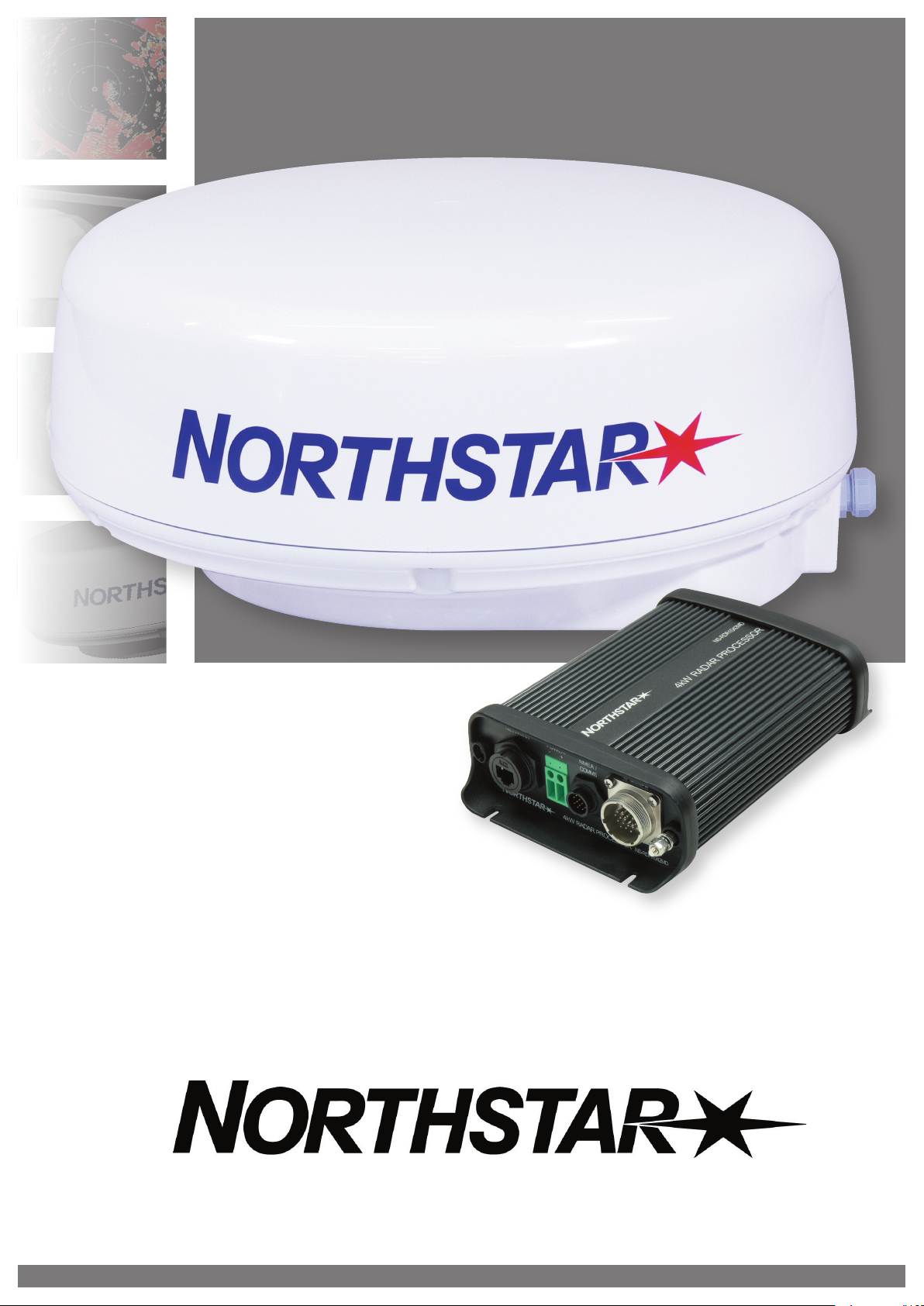
Northstar 4 kW Radar
Installation Manual

FCC Statement
Note: This equipment has been tested and found to comply with the limits for a Class B digital device,
pursuant to Part 15 of the FCC Rules. These limits are designed to provide reasonable protection
against harmful interference in a normal installation. This equipment generates, uses and can radiate
radio frequency energy and, if not installed and used in accordance with the instructions, may cause
harmful interference to radio communications. However, there is no guarantee that interference will
not occur in a particular installation. If this equipment does cause harmful interference to radio or
television reception, which can be determined by turning the equipment off and on, the user is
encouraged to try to correct the interference by one or more of the following measures:
Reorient or relocate the receiving antenna.
Increase the separation between the equipment and receiver.
Connect the equipment into an output on a circuit different from that to which the receiver
is connected.
Consult the dealer or an experienced technician for help.
A shielded cable must be used when connecting a peripheral to the serial ports.
Industry Canada
Operation is subject to the following two conditions (1) this device may not cause interference, and (2)
this device must accept any interference, including interference that may cause undesired operation
of the device.
Compliance Statement
EMC compliance:
USA (FCC): Part 15 Class B
Disclaimer
As Northstar is continuously improving this product we retain the right to make changes to the
product at any time which may not be reflected in this version of the manual. Please contact your
nearest Northstar distributor if you require any further assistance.
It is the owner’s sole responsibility to install and use the instrument and transducers in a manner that
will not cause accidents, personal injury or property damage. The user of this product is solely
responsible for observing safe boating practices.
BRUNSWICK NEW TECHNOLOGIES INC. AND ITS SUBSIDIARIES AND AFFILIATES DISCLAIM ALL
LIABILITY FOR ANY USE OF THIS PRODUCT IN A WAY THAT MAY CAUSE ACCIDENTS, DAMAGE OR THAT
MAY VIOLATE THE LAW.
Governing Language: This statement, any instruction manuals, user guides and other information
relating to the product (Documentation) may be translated to, or has been translated from, another
language (Translation). In the event of any conflict between any Translation of the Documentation,
the English language version of the Documentation will be the official version of the Documentation.
This manual represents the product as at the time of printing. Brunswick New Technologies Inc. and its
subsidiaries and affiliates reserve the right to make changes to specifications without notice.
Copyright © 2006 Brunswick New Technologies Inc. Northstar™ is a registered trademark of Brunswick
New Technologies Inc.

Warranty
The Northstar Warranty Statement is supplied as a separate document.
It is shipped with the Product Registration Card.
In case of any queries, refer to www.northstarnav.com.
Feedback from you
Your feedback is important and helps Northstar ensure that this manual is a valuable resource for all
marine technicians. E-mail your comments or suggestions about this manual to the following address:
manuals@northstarnav.com.


Contents
FCC Statement
Industry Canada
Compliance Statement
Disclaimer
Warranty
Feedback from you
1 Preface 3
2 Introduction to the Northstar radar 5
2.1 4 kW Radar system overview .................................................................................................................................................5
2.2 Check the 4 kW radar parts..................................................................................................................................................... 6
3 Install the radar 9
3.1 Choose the scanner location .................................................................................................................................................9
3.1.1 Power boat installations........................................................................................................................................................10
3.1.2 Yacht installations....................................................................................................................................................................11
3.2 How to find the optimum height for the scanner ........................................................................................................12
3.3 How to find the maximum detection range...................................................................................................................12
3.4 How to reduce false echoes and shadow zones ...........................................................................................................13
3.5 4 kW scanner dimensions .....................................................................................................................................................14
3.6 Install a scanner on a trestle.................................................................................................................................................15
3.7 Install the 4 kW scanner unit................................................................................................................................................15
3.8 Install the radar processor.....................................................................................................................................................16
4 Wire the radar system 17
4.1 Wiring guidelines.....................................................................................................................................................................17
4.2 Connect the 4 kW interconnection cable (NS00310X) to the scanner...................................................................17
4.3 Run the 4 kW interconnection cable (NS00310X) to the radar processor............................................................19
4.4 4 kW radar processor connectors.......................................................................................................................................20
4.5 Connect the 4 kW radar processor to a 6000i or 6100i display................................................................................22
4.5.1 Connect the radar communications cable (NS003107) to the junction box .......................................................23
4.5.2 Configure the remote power control for a 6000i or 6100i (common power source) .......................................25
4.5.3 Configure the remote power control for a 6000i or 6100i (different power sources)......................................26
4.6 Connect the 4 kW radar processor to an 8000i display...............................................................................................28
4.6.1 Configure the remote power control for an 8000i.......................................................................................................28
4.6.2 Connect an 8000i network cable (NS00481X)................................................................................................................29
4.6.3 Connect the optional NMEA compass for an 8000i .....................................................................................................29
4.7 Connect the power cable......................................................................................................................................................29
4.8 Connect the ground wire......................................................................................................................................................30
4.9 Radar system checklist...........................................................................................................................................................31
5 Set up the radar with the Northstar 8000i system 32
Northstar 4 kW Radar Installation Manual 1

6 Set up the radar with the Northstar 6000i or 6100i 33
6.1 Turn the radar on and off...................................................................................................................................................... 33
6.1.1 Before you turn on the radar for the first time...............................................................................................................33
6.1.2 Turn the radar on.....................................................................................................................................................................33
6.1.3 Turn the radar off..................................................................................................................................................................... 33
6.2 Configure the navigator communciations......................................................................................................................34
6.3 Heading sensor requirements.............................................................................................................................................34
6.3.1 Disable the heading sensor input......................................................................................................................................34
6.4 Calibrate the radar...................................................................................................................................................................35
6.4.1 Prepare for calibration...........................................................................................................................................................35
6.4.2 Tune the radar ..........................................................................................................................................................................35
6.4.3 Set the STC Curve ....................................................................................................................................................................35
6.4.4 Set the trigger delay ...............................................................................................................................................................36
6.4.5 Set the heading calibration (heading sensor installed).............................................................................................. 37
6.4.6 Set the heading calibration (heading sensor not installed)......................................................................................37
6.5 Adjust the appearance settings..........................................................................................................................................37
6.6 Restore all the factory settings............................................................................................................................................38
6.6.1 Restore the factory appearance settings.........................................................................................................................38
7 Maintenance 39
7.1 General maintenance.............................................................................................................................................................39
7.2 Scanner maintenance ............................................................................................................................................................39
7.3 Other maintenance items..................................................................................................................................................... 39
8 Troubleshoot the radar 40
8.1 Technical support, service and repairs............................................................................................................................. 40
8.2 Radar is not operating correctly .........................................................................................................................................40
8.3 If the scanner fails to turn .....................................................................................................................................................41
8.4 How to reduce noise and interference.............................................................................................................................41
8.5 Make sure the power is present and correctly wired ..................................................................................................42
8.6 Confirm the equipment installed.......................................................................................................................................42
8.7 Are Range Rings displayed?.................................................................................................................................................42
9 Manual tuning procedure for the 6000i or 6100i system 43
10 4 kW Specifications 44
2 Northstar 4 kW Radar Installation Manual
1
Preface
This manual explains how to install the scanner and the radar processor. It also explains how to set up
the radar system after installation and gives information on troubleshooting.
This manual is supplementary to the Northstar 6000i/6100i Installation and Operation Manual and the
Northstar 8000i System Setup Manual.
This manual is written for professional marine technicians, installation technicians, and service
technicians, and can be used for information by dealers.
PLEASE READ CAREFULLY BEFORE USE
WARNING indicates a potentially hazardous situation which, if not avoided, could
result in death or serious injury.
CAUTION indicates a potentially hazardous situation which, if not avoided, may result
in minor or moderate injury.
CAUTION used without the safety alert symbol indicates a potentially hazardous
situation which, if not avoided, may result in property damage.
Ensure that mains power is OFF before starting installation or servicing work. Electrical shock, fire or injury can
result if electrical power remains ON, or is switched ON, during installation or servicing work.
A potentially lethal high voltage is present and can remain for a period of time after the equipment is turned OFF.
Ensure that capacitors are discharged with an Earthed wire before starting servicing work.
Ensure that internal surfaces are no longer charged before you touch them.
To minimize accidents, wear dry cotton gloves and avoid touching equipment with both hands unless absolutely
necessary. Always work from a stable position to avoid slipping or falling onto the equipment.
The radar is intended ONLY as an aid to navigation.
The skipper must make final decisions based on all of the information sources to hand
and must not rely solely on the radar.
Northstar 4 kW Radar Installation Manual 3
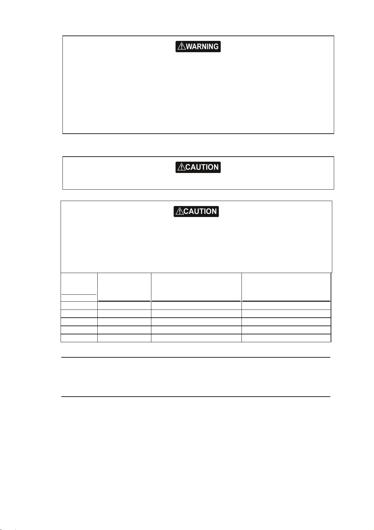
Only qualified personnel should install or service this equipment. Installation or servicing work that is done by
non-qualified personnel can result in equipment breakdown, poor performance of the equipment, fire, electrical
and physical hazards, injury or death.
Wear safety equipment such as a hard hat and a safety belt at all times when installing or working on the scanner.
The scanner is usually installed in an elevated position and serious injury or death can result if a person falls while
installing or working on it. It may be necessary to construct a working platform, particularly for the installation.
Install the scanner in an elevated position to minimize the radiation hazard to personnel.
Never look directly into the scanner at close range while the radar is operating.
Radar scanners emits electromagnetic energy at a frequency that can be harmful at close range. Always keep the
recommended safe distance from the scanner as follows:
Scanner
Model
Vertical beam
angle of scanner
(degrees)
Minimum safe distance (100
Watts per m² average power
density) Note 1
Minimum safe distance (10
Watts per m² average power
density) Note 2
2 kW 30 1.6 ft (0.5 m) 4.6 ft (1.4 m)
4 kW 25 3 ft (0.9 m) 9.3 ft (2.8 m)
6 kW 20 3.6 ft (1.1 m) 11.5 ft (3.5 m)
10 kW 20 9.5 ft (2.9 m) 3 ft (9.0 m)
25 kW 20 18 ft (5.5 m) 57 ft (17.4 m)
NOTES: Limits apply to exposure within the vertical beam angle.
Note 1: Peak occupational exposure limit pursuant to IEC 60936 Clause 3.27 and IEC 62252 Clause 4.32
Note 2: General public exposure limit pursuant to IEC 60936 Clause 3.27 and IEC 62252 Clause 4.32
4 Northstar 4 kW Radar Installation Manual

2
Introduction to the Northstar radar
The Northstar radars are designed as an option available to the Northstar 6000i, 6100i, or 8000i
systems.
A variety of scanners are available (2 kW, 4 kW, 6 kW, 10 kW and 25 kW) to suit different customer
requirements. Each scanner model has a corresponding radar processor model.
2.1
4 kW Radar system overview
The 4 kW radar system is intended for use in a marine environment. It consists of a dome connected
to a 4 kW radar processor by a prefabricated interconnection cable (NS00310X), which is available in
two lengths.
where A is the radar processor, B is the vessel's power supply, and C is the Network Linker (NS004721).
If the radar processor is connected to a Northstar 6000i or 6100i, it communicates with the display unit
through the 6000i and 6100i radar communications cable (NS003107). An optional extension cable
(NS003108) is available.
If the radar processor is connected to a Northstar 8000i system, it communicates with the 8000i
Network Linker (NS004721) through the 8000i network cable (NS00481X).
DC power for the scanner and radar processor is provided through a power cable that connects the
radar processor to the vessel's DC power supply. The power cable is not supplied.
Northstar 4 kW Radar Installation Manual 5
2.2
Check the 4 kW radar parts
The NS-RDR1042MD radar system consists of a scanner, a radar processor, and associated cables.
There are two basic options for the 4 kW radar:
NS004791R is the standard 4 kW radar scanner component, consisting of a box containing
the scanner and the 49 ft (15 m) interconnection cable (NS003102).
NS004791M is the alternative 4 kW radar scanner component, consisting of a box
containing only the scanner. This radar system is designed for use with the (65.5 ft) 20 m
interconnection cable (NS003103) which is ordered and supplied separately.
If you want to use an interconnection cable length other than the 49 ft (15 m) or 65.5 ft (20 m) options,
please consult your Northstar dealer.
If you're connecting the 4 kW radar to a Northstar 6000i or 6100i system, a 10 ft (3 m) radar
communications cable (NS003107) is supplied with the 6000i or 6100i system. If this is not long
enough, an optional 6 ft (1.8 m) extension cable (NS003108) for the radar communications cable can
be added between the radar processor and the 6000i. This extension cable is not supplied as standard,
and must be ordered separately.
If you're connecting the radar to a Northstar 8000i system, you need the 8000i network cable
(NS00481X) which is available is several lengths. This is not supplied as standard, and must be ordered
separately.
Unpack the boxes carefully and check the contents against the packing lists. If anything is missing,
contact your distributor.
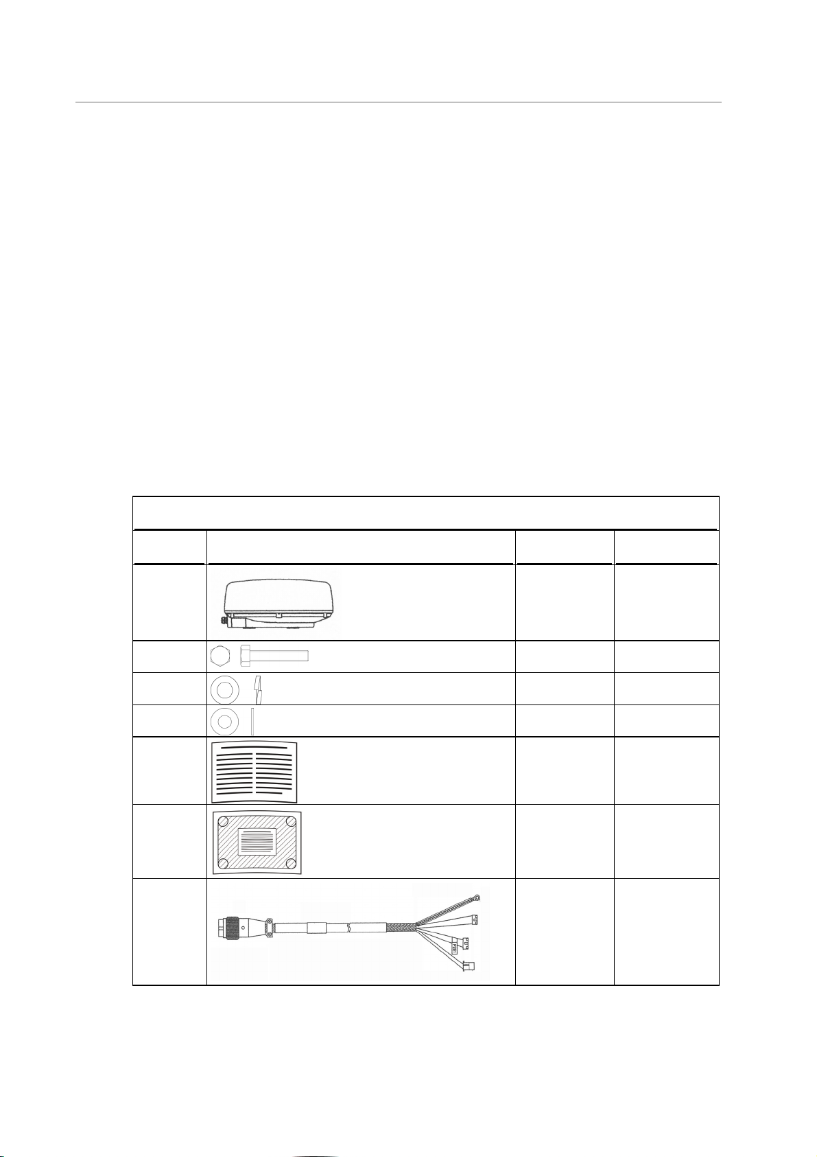
NS004791R 4 kW scanner standard components
Quantity Item Part name Part no.
1
4
4
4
1
1
1
Scanner unit NS004791
M8x30
Hexagonal bolt
M8 Spring
washer
M8 Plain washer Part of Hardware
Packing list LA000453A
Mounting
template
Interconnection
cable 49 ft (15
m).
Part of Hardware
kit HR000067
Part of Hardware
kit HR000067
kit HR000067
LA000452A
NS003102
49 ft (15 m)
6 Northstar 4 kW Radar Installation Manual

NS004791M 4 kW scanner standard components
Quantity Item Part name Part no.
1
Scanner unit NS004791
4
4
4
1
M8x30
Hexagonal bolt
M8 Spring
washer
Part of Hardware
kit HR000067
Part of Hardware
kit HR000067
M8 Plain washer Part of Hardware
kit HR000067
Packing list LA000453A
1
Mounting
LA000452A
template
NS004781 4 kW radar processor standard components
Quantity Item Part name Part no.
1
1
1
1
4 kW radar
NS004781
processor box
This manual MN000356A
Installation
LA000276A
template
Product
CD000085A
Registration Card
1
Warranty CD000260A
Northstar 4 kW Radar Installation Manual 7

1
1
4
License
agreement
Spare 3A fuse Part of Hardware
Mounting screw Part of Hardware
LA000624A
kit HR000061
kit HR000061
NS003103 Optional longer length scanner interconnection cable - order separately
Quantity Item Part name Part no.
1
Interconnection
cable 65.5 ft (20
m)
NS003103 length
65.5 ft (20 m)
NS00481X cable for 8000i installation only - order separately
Quantity Item Part name Part no.
1
8000i Network
cable (for radar
communications
in an 8000i
installation
ONLY.
NS004810 length
1.6 ft (0.5 m)
NS004811 length
6.5 ft (2 m)
NS004812 length
16.4 ft (5 m)
NS004813 length
32.8 ft (10 m)
NS003107 cable for 6000i and 6100i installations only - supplied with 6000i and 6100i system
Quantity Item Part name Part No
1
Radar
communications
cable for 6000i
and 6100i
installations
ONLY.
NS003107
NS003108 Optional extension cable for 6000i and 6100i installations only - order separately
Quantity Item Part name Part no.
1
8 Northstar 4 kW Radar Installation Manual
Radar
communications
extension cable
for 6000i and
6100i installation
ONLY.
NS003108

3
Install the radar
A radar unit should only be installed by a qualified marine technician, as potentially lethal high
voltage is present along with heavy rotating parts. There is a transmit interlock that prevents radar
transmissions if the scanner is not rotating. However, a high voltage remains for a period of time after
the system is turned off. If you are not familiar with this type of electronics, consult with a trained
service or installation technician before attempting to service any part of the equipment.
Installation includes
mechanical mounting
electrical wiring
configuring the 6000i or 6100i system or 8000i system to work with the radar
adjusting the radar for proper performance.
Don't take any shortcuts, and follow these instructions carefully.
NOTE: For the radar overlay to function properly on the chart screen, you must correctly install and
calibrate a separate heading sensor. Without the heading sensor, you cannot overlay the chart. A 10
Hz heading output rate is required for best radar/chart overlay performance.
3.1
This section explains how to:
choose the correct location for the scanner
install the scanner on a power boat or a yacht
choose the correct location for the radar processor
install the radar processor
Read the important warning and safety information in the Preface before you install the radar.
Choose the scanner location
The radar's ability to detect targets depends greatly on the position of its scanner. The ideal location
for the scanner is high above the vessel's keel line where there aren't any obstacles.
The higher the installation position, the longer the radar ranging distance, but the minimum range
that the radar can detect targets increases the higher that the radar is mounted.
Also see the sections on installing the scanner on a power boat or yacht.
When you're deciding on the location, consider the following:
the length of the interconnection cable supplied with your radar is usually sufficient. If you
think you'll need a longer cable, consult your Northstar dealer before installation, because a
longer cable may reduce the performance of the radar.
if the roof of the wheelhouse is the highest existing location, consider installing a radar mast
or a pedestal on which you can mount the scanner. You may also need to construct a
working platform for your own safety during installation and servicing work.
if you mount the scanner on a pedestal or base, ensure that rain and sea spray can drain
away from it rapidly.
if you locate the scanner on the mast, position it on the forward side so that there is a clear
view to the front of the vessel.
the scanner is usually installed parallel to line of the keel
ensure that the location site provides the scanner with a clear view of the front of the vessel.
Northstar 4 kW Radar Installation Manual 9
DON'T DO THIS!
DON'T install the scanner too high up, where its weight will alter the stability of the vessel
and cause degradation of the radar picture over short ranges (see "How to find the
optimum height for the scanner").
DON'T install the scanner close to lamps or exhaust outlets. The heat emissions may cause
the equipment to breakdown and soot and smoke will degrade the performance of the
radar.
DON'T install the scanner close to the antennas of other equipment such as direction
finders, VHF antennas, GPS equipment and so on, because it may cause interference.
DON'T install the scanner where a large obstruction (such as an exhaust stack) is at the same
level as the beam, because the obstruction is likely to generate false echoes and/or shadow
zones.
DON'T install the scanner where it will be subjected to strong vibrations (such as a derrick
post) because these vibrations will degrade the performance of the radar.
DON'T install an open array close to halyards or flags because the wind could wrap these
around the scanner and jam it.
DON'T install the scanner inside of the recommended compass safe distances of any navigation instruments such
as the magnetic compass and the chronometer. The compass safe distances are as follows:
2 kW radar STD 2.3 ft (0.7 m)
4 kW radar STD 6.5 ft (2.0 m)
6 kW radar STD 7.5 ft (2.3 m)
10 kW radar STD 7.9 ft (2.4 m)
25 kW radar STD 7.9 ft (2.4 m)
3.1.1 Power boat installations
Normally, you should install the scanner horizontally, to produce an equal sweep around the power
boat:
STEER 1.6 ft (0.5 m)
STEER 5 ft (1.5 m)
STEER 5.7 ft (1.75 m)
STEER 6 ft (1.8 m)
STEER 6 ft (1.8 m)
10 Northstar 4 kW Radar Installation Manual

However, when the power boat is traveling at high speed, the bow rises up out of the water and if the
elevation angle (trim) of the bow is raised up so that it equals, or exceeds, 50% of the vertical beam
width of the radar, this can cause two problems:
ahead of the power boat, the beam is projected too high to sweep the water surface
effectively. Targets can be missed completely or appear at a very poor resolution on the
display screen.
astern of the power boat, the beam is projected too low and is concentrated over a small
area of water so that sea clutter becomes a problem on the display screen.
In this case, you're recommended to install the scanner so that is tilted down at the front, at an angle
that will produce an almost horizontal sweep when the power boat is running at speed.
3.1.2 Yacht installations
Normally you should install the scanner horizontally, to produce an equal sweep around the yacht.
However, a yacht heels over to the lee side, and when the heel angle exceeds 50% of the vertical beam
width of the radar, this can cause two problems:
on the windward side of the yacht, the beam is projected too high to sweep the water
surface effectively. Targets can be missed completely or appear at very poor resolution on
the display unit.
on the lee side of the yacht, the beam is projected too low and is concentrated over a small
area of water so that sea clutter becomes a problem on the display unit.
In this case, you're recommended to install the scanner on a gimbal mounting so that it can operate
effectively in a heavy swell or when the yacht is heeled over.
Northstar 4 kW Radar Installation Manual 11

3.2
How to find the optimum height for the scanner
The optimum height for the scanner is as close as possible to the A-B line for best performance.
How to find the A-B Line:
The vertical extent of the radar beam is 2T°, so most of the radar beam is concentrated within this
angle, meaning that outside of this angle the radar beam will be very weak.
Scanner model
2 kW 15
4 kW 12.5
6 kW 10
10 kW 10
25 kW 10
An example of an A-B Line is shown in the picture. If you install the scanner below the A-B line, the
scanner will be too low. It will be difficult to acquire distant targets and the superstructure will be
more likely to impede the passage of the beam and generate false echoes. If the scanner is installed
too high above the A-B line, the beam will miss close targets and increase sea clutter return.
T° value (half the -3 dB beam width)
3.3
You can find the A-B line for any vessel as follows:
1. Using a drawing of the vessel, lay a rule along the line of the main deck and continue this
forwards as a dashed line extending beyond the bow.
2. Using a protractor, measure the T° value (for your scanner model) below the dashed line at
the bow and draw in a new line along this angle.
3. Extend the new line back beyond the stern of the vessel. This is the A-B line.
How to find the maximum detection range
Propagation of the radar beam can vary, depending on the properties of the air through which it's
travelling. Under normal conditions, the distance that the radar beam travels is approximately 10%
further than the distance to the optical horizon.
You can calculate the theoretical distance traveled by the radar beam using the following formula:
D = 2.23 (¹h1 + ¹h2)
12 Northstar 4 kW Radar Installation Manual