


CONDENSING TANKLESS GAS WATER HEATER
Installation Manual
Models
NRCP1112-DV / NRCP982-DV (Eco TOUGH)
• Natural Gas(NG) / Liquid Propane Gas (LP)
Thank you for purchasing this Noritz Tankless Gas Water Heater. Before using, please:
Read this guide completely for operation instructions.
Completely fill out the warranty registration card (included separately) and mail the detachable portion to Noritz America Corporation. Keep this guide (and the remainder of the warranty registration card) where
it can be found whenever necessary.
Installation must conform with local codes, or in the absence of local codes, the National Fuel Gas Code, ANSI Z223.1/NFPA 54latest edition and/or CSA B149.1, Natural Gas and Propane Installation Code (NSCNGPIC). Noritz America reserves the right to discontinue, or change at any time, the designs and/or specifications of its products without notice.
 WARNING
If the information in these instructions is not followed exactly, a fire or explosion may result, causing property damage, personal injury, or death.
–Do not store or use gasoline or other inflammable vapors and liquids in the vicinity of this or any other appliance.
–WHAT TO DO IF YOU SMELL GAS
•Do not try to light any appliance.
•Do not touch any electrical switch; do not use any phone in your building.
•Immediately call your gas supplier from a neighbor’s phone. Follow the gas supplier’s instructions.
•If you cannot reach your gas supplier, call the fire department.
–Installation and service must be performed by a qualified installer, service agency or the gas supplier.
Rev.03/16

Chapter 1 Product Accessories
Chapter 2 Product Specifications
Chapter 3 Safety Requirements
Chapter 4 |
Installation |
Chapter 5 |
Maintenance |
Memo
1-1 Included Accessories |
3 |
1-2 Optional Accessories |
3 |
2-1 Specifications |
4 |
2-2 Dimensions & Connections |
5 |
3-1 Safety Precautions |
6 |
3-2 Before Installation |
7 |
3-3 Choosing Installation Site |
8 |
3-4 High Elevation Installations |
9 |
3-5 Installation Clearance |
10 |
4-1 Securing to the wall |
13 |
4-2 Vent Pipe Installation |
14 |
4-3 Gas Piping |
20 |
4-4 Water Piping |
23 |
4-5 Condensate Piping |
25 |
4-6 Plumbing Application |
26 |
4-7 Electrical Wiring |
30 |
4-8 Setting the Control Panel |
31 |
(Clock Adjustment & Recirculation Timer Setting, High Elevation Setting) |
|
4-9 Quick Connect Multi System Installation |
35 |
4-10 Common Vent |
37 |
5-1 Maintenance |
39 |
5-2 Final Check List |
41 |
|
42 |
2

Chapter 1. – Product Accessories
1-1. Included AccessoriesThe following accessories are included with the unit. Check for any missing items before starting installation.
Part |
Shape |
Q’ty |
Water Heater |
|
1 |
Anchors / |
|
1 |
Wall mounting |
|
|
bracket / |
|
each |
Emergency Kit |
|
|
Part |
Shape |
Q’ty |
|
|
|
Owner’s Guide, |
|
|
Warranty Card, |
|
1 |
InstallationManual, |
|
|
TechnicalData Sheet, |
|
each |
QuickInstallationGuide, |
|
|
Part List |
|
|
|
|
|
Vent screens with |
|
2 |
Finishing |
|
|
(3") |
|
|
|
|
|
1-2. Optional Accessories The accessories listed below are not included with the unit, but may be necessary for installation.
Part |
Shape |
Q’ty |
|
|
|
PVC Terminal |
|
1 |
VK3-H-PVC |
|
|
|
|
VK3-PVC-VAS |
1 |
PVC Terminal |
1 |
|
PRC-1 |
||
|
SV Conversion Kit
(#SV-CK-3) 1
•90 Elbow (With Inlet Screen)
Neutralizer
(NC-1) 1
(For 1 water heater)
Part |
|
Shape |
Q’ty |
|||||
|
|
|
|
|
|
|
|
|
Horizontal |
|
|
|
|
|
|
|
1 |
Hood |
|
|
|
|
|
|
|
|
Termination |
|
|
|
|
|
|
|
each |
PVT-HL |
|
|
|
|
|
|
|
|
|
|
|
|
|
|
|
|
|
Isolation |
|
|
|
|
|
|
|
|
Valves |
|
|
|
|
|
|
|
1 |
(includes |
|
|
|
|
|
|
|
|
|
|
|
|
|
|
|
each |
|
pressure |
|
|
|
|
|
|
|
|
|
|
|
|
|
|
|
|
|
relief valve) |
|
|
|
|
|
|
|
|
|
|
|
|
|
|
|
|
|
Vent screens |
|
|
|
|
|
|
|
|
with Finishing |
|
|
|
|
|
|
|
2 |
(2") |
|
|
|
|
|
|
|
|
(After market) |
|
|
|
|
|
|
|
|
|
|
|
|
|
|
|
|
|
Quick |
|
|
|
|
|
|
|
|
|
|
|
|
|
|
|
|
|
Connect |
|
|
|
|
|
|
|
1 |
|
|
|
|
|
|
|
||
|
|
|
|
|
|
|
||
Cord |
|
|
|
|
|
|
|
|
|
|
|
|
|
|
|
||
|
|
|
|
|
|
|
|
|
QC-NRCP |
|
|
|
|
|
|
|
|
|
|
|
|
|
|
|
|
|
|
|
|
|
|
|
|
|
|
3

Chapter 2. – Product Specifications |
Specifications |
2-1. SpecificationsSpecifications may be changed without prior notice.The capacity may differ slightly, depending on the water pressure, water supply, piping conditions, and water temperature.
Model Name |
|
|
|
NRCP1112-DV |
|
NRCP982-DV |
||||||
|
|
|
MAX |
|
199,000 Btu/h |
|
180,000 Btu/h |
|||||
Gas Input Rate |
|
|
MIN |
|
18,000 Btu/h |
|
18,000 Btu/h |
|||||
|
|
High Altitude (2,500~4,500ft) |
180,000 Btu/h |
|
180,000 Btu/h |
|||||||
|
|
|
|
|
|
|
|
|
|
|
|
|
|
|
|
35°F Rise |
|
11.1 Gal |
|
10.1 Gal |
|
||||
Hot Water Capacity |
|
|
45°F Rise |
|
8.7 Gal |
|
7.8 Gal |
|
||||
|
|
|
77°F Rise |
|
5.1 Gal |
|
4.6 Gal |
|
||||
|
Installation |
|
|
|
|
|
Indoor Wall Hung |
|
||||
|
Flue System |
|
|
|
|
Sealed Combustion Direct Vent, Single Vent |
|
|||||
Max Vent Run |
|
|
|
2″(50ft) / 3″(100ft) Schedule 40 PVC, CPVC, PP |
||||||||
|
|
|
|
|
|
|
|
|
||||
Orifice Size |
|
NG (Gas / Needle) |
|
|
0.381″(9.7mm) / 0.389″(9.9mm) |
|
||||||
|
|
|
|
|
|
|
|
|
|
|
|
|
|
LP (Gas / Needle) |
|
|
0.307″(7.8mm) / 0.315″(8.0mm) |
|
|||||||
|
|
|
|
|
||||||||
Gas Supply Pressure |
|
NG |
|
|
|
3.5˝ WC to 10.5˝ WC |
|
|||||
|
LP |
|
|
|
8.0˝ WC to 14˝ WC |
|
||||||
|
|
|
|
|
|
|
||||||
|
|
|
Gas Type |
NG |
|
LP |
|
NG |
|
LP |
||
|
|
Low Fire |
|
2″ VENT |
-0.03 WC |
|
-0.06 WC |
|
-0.03 WC |
|
-0.06 WC |
|
Manifold Pressure |
|
|
3″ VENT |
-0.03 WC |
|
-0.06 WC |
|
-0.03 WC |
|
-0.06 WC |
||
|
|
|
|
|
|
|
||||||
|
|
High Fire |
|
2″ VENT |
-0.04 WC |
|
-0.07 WC |
|
-0.04 WC |
|
-0.07 WC |
|
|
|
|
3″ VENT |
-0.04 WC |
|
-0.07 WC |
|
-0.04 WC |
|
-0.07 WC |
||
|
|
|
|
|
|
|
|
|||||
|
|
|
Main Supply |
|
|
120V 60Hz |
|
|||||
Power Supply |
|
|
Maximum |
|
|
172W(82W+90W_PUMP) |
|
|||||
|
|
Power Consumption |
|
|
|
|||||||
|
|
|
|
|
|
|
|
|
||||
Ignition System |
|
|
|
Direct Electronic Ignition / Automatic Flame Sensing |
||||||||
Burner System |
|
|
|
|
|
Premixed Metal Fiber Burner |
|
|||||
|
|
|
|
|
|
|
|
|
||||
Gas Valve System |
|
|
|
|
|
Air ratio valve |
|
|||||
Minimum Flow Activation Flow |
|
|
|
|
0.5 GPM |
|
||||||
Internal Pipe Material |
|
|
|
STS 304, Copper Tubing |
|
|||||||
|
Dimensions |
|
|
|
|
|
W17.3″ – H28.7″ – D14.8″ |
|
||||
|
Weight |
|
|
|
|
|
|
85 lbs |
|
|||
Water Holding Capacity |
|
|
|
Under 2 Gallon |
|
|||||||
Control Panel / Main Controller |
|
|
|
P-950C / NGTH-9700C |
|
|||||||
Water Pressure |
|
|
MAX |
|
|
|
Hot water 150 psi |
|
||||
|
|
MIN |
|
|
|
|
15 psi |
|
||||
|
|
|
|
|
|
|
|
|||||
Materials |
|
|
Casing |
|
|
|
Cold Rolled Carbon Steel |
|
||||
|
Heat Exchanger |
|
|
Heat Exchanger : STS 304 |
|
|||||||
|
|
|
|
|
||||||||
|
|
|
|
|
|
|
Flame Sensor, Overheat Cut Off Limit Switch , |
|
||||
Safety Devices |
|
|
|
Gas Leak Detector sensor, Water Leak Detector Sensor |
||||||||
|
|
|
|
|
Exhaust Temperature Sensor, |
|
||||||
|
|
|
|
|
|
|
|
|
||||
|
|
|
|
|
|
|
|
Water Temperature Sensor |
|
|||
|
|
|
|
|
|
|
|
|
|
|
|
|
4

Chapter 2. – Product Specifications |
Dimensions & Connections |
2-2. Dimensions & Connections
|
[101mm] |
|
|
|
|
|
|
11.5" [292mm] |
|
|
|
|
|
|
|
4.0" |
|
4.6" [117mm] |
|
|
|
|
|
|
[730mm] |
7 |
|
28.7" |
||
|
1 |
|
|
|
26 |
|
|
|
|
25 |
2 |
|
|
|
24 |
|
|
|
23 |
|
3 |
|
|
|
|
|
|
|
|
|
4 |
|
|
|
22 |
5 |
|
|
|
|
|
|
|
21 |
|
|
|
|
|
|
6 |
|
|
|
|
|
|
|
|
20 |
8 |
|
|
|
19 |
|
|
|
18 |
|
9 |
|
|
|
|
|
|
|
17 |
|
|
|
|
|
|
|
|
|
|
16 |
10 |
11 |
13 |
14 |
15 |
|
12 |
|
||
|
|
|
|
|
|
|
|
|
|
|
|
|
|
|
|
|
|
|
|
|
|
|
2.6" [67mm] |
|||
|
|
|
|
|
|
|
|
||||
|
[156mm]6.1" |
|
[142mm]5.6" |
|
[60mm]2.4" |
|
|
||||
|
|
|
|
|
|
|
|
||||
|
|
|
|
|
|
|
|
|
|
|
|
|
|
|
|
|
|
|
|
3.2" [81mm] |
|
|
|
|
|
|
|
|
|
|
|
|
|
|
|
|
|
|
|
|
|
|
|
6.8" [173mm] |
|||
|
|
|
|
|
|
|
|
9.8" [250mm] |
|
|
|
|
|
|
|
|
|
|
|
|
|
|
|
|
|
|
|
|
|
|
|
13.6" [346mm] |
|
|
|
|
|
|
|
|
|
|
|
||||
|
|
|
|
|
|
|
|
||||
|
|
|
|
|
|
|
|
|
|
|
|
|
|
|
|
|
Description |
|
Size |
||||
A |
|
|
|
|
|
Exhaust |
|
3" |
|
|
|
B |
|
|
|
|
|
Air Intake |
|
3" |
|
|
|
C |
|
|
|
|
|
Hot Water |
|
3/4" |
|
|
|
D |
|
|
|
|
|
Condensate |
|
1/2" |
|
|
|
E |
|
|
|
Recirculation Return |
|
3/4" |
|
|
|
||
F |
|
|
|
|
|
Cold Water |
|
3/4" |
|
|
|
G |
|
|
|
|
|
Gas |
|
3/4" |
|
|
|
|
|
|
|
|
|
|
|
|
|
|
|
NO |
|
|
Name of Component |
|
|
|
|
||||
1Exhaust
2Igniter
3Ignition Plug
4Burner High Limit Switch
5Primary Heat Exchanger
6Secondary Heat Exchanger
7Control Panel
8Water Mixing Valve
9Recirculation Pump
10Hot Water Connection
11Condensate Trap
12Recirculation Return Connection with Filter
13Computer Board
14Cold Water Connection
15Cold Water Filter
16Gas Connection
17Manual Power Switch
18Flow Sensor
19Water Control Valve
20Air Pressure Switch
21Flame Sensor
22Gas Valve
23AGM (Air Gas Mixer)
24Fan Motor
25Internal Air Intake Filter
26Air Intake
5
Chapter 3. – Safety Requirements |
Safety Precautions |
3-1. Safety Precautions
 WARNING
To avoid product damage, personal injury, or even possible death, carefully read, understand, and follow all the instructions in the Installation and Owner’s Guide before installation, operation and service the Water Heater.
Noritz cannot anticipate every circumstance that might involve a potential hazard. Therefore, all possible incidents are not included in our warnings. Proper installation, operation, and service are your responsibility.
You must make sure that the operation and settings of the Water Heater are safe for you and for others.
This manual provides Safety Symbols. When the user fails to adhere to the following requirement, it will cause death, serious damages, and a great property loss.
For safety symbols, ‘DANGER’, ‘WARNING’, ‘CAUTION’are indicated and the definitions for these terms are as follow:
 DANGER
Indicatesanimminentlyhazardoussituationwhich,ifnotavoided,willresultindeathorserious injury. This signal word is limited to the most extreme situations.
 WARNING
Indicates a potentially hazardous situation which, if not avoided, could result in death or serious injury.
 CAUTION
Indicates a potentially hazardous situation which, if not avoided, may result in minor or moderate injury. It is also used to alert against unsafe practices and hazards involving only property damage.
6

Chapter 3. – Safety Requirements |
Before Installation |
3-2. Before Installation
 DANGER
Check the fixing brackets and vent pipe yearly for damage or wear. Replace if necessary.
 WARNING
Precautions on Vent Pipe Replacement
The vent system will almost certainly need to be replaced when this appliance is being installed.
Only use vent materials that are specified in this Installation Manual for use on this appliance. Refer to the “Vent Pipe Installation” section for details. If PVC, CPVC, or Category IV listed pipe is already installed, check for punctures, cracks, or blockages and consult with the vent pipe manufacturer before reusing.
Improper venting may result in fires, property damage or exposure to Carbon Monoxide.
Snow Precaution
If this product will be installed in an area where snow is known to accumulate, protect the vent termination from blockage by snow drifts or damage from snow falling off of roofs.
Check the Gas
Check that the rating plate indicates the correct type of gas.
Check that the gas supply line is sized for 199,000 Btu/h.
Check the Power
The power supply required is 120VAC, at 60Hz.
Using the incorrect voltage may result in fire or electric shock.
 CAUTION
Do Not Use Equipment for Purposes Other Than Those Specified.
Do not use for other than increasing the temperature of the water supply, as unexpected accidents may occur as a result.
Check Water Supply Quality
If the water supply is in excess of 12 grains per gallon (200 mg/L) of hardness, acidic or otherwise impure, treat the water with approved methods in order to ensure full warranty coverage.
7

Chapter 3. – Safety Requirements |
Choosing Installation Site |
3-3. Choosing Installation Site
Locate the appliance in an area where leakage from the unit or connections will not result in damage to the area adjacent to the appliance or to the lower floors of the structure. When such locations cannot be avoided, it is required that a suitable drain pan, adequately drained, be installed under the appliance.
The pan must not restrict combustion air flow.
 DANGER
Locate the vent terminal so that there are no obstacles around the termination and so that exhaust can’t accumulate. Do not enclose the termination with corrugated metal or other materials.
 WARNING
Avoid places where fires are common, such as those where gasoline, benzene and adhesives are handled, or places in which corrosive gases
(ammonia, chlorine, sulfur, ethylene compounds, acids) are present. Using the incorrect voltage may result in fire or cracking.
Avoid installation in places where dust or debris will accumulate. Dust may block the air-supply opening, causing the performance of the device fan to drop and incomplete combustion to occur as a result.
Avoid installation in places where special chemical agents (e.g., hair spray or spray detergent) are used. Ignition failures and malfunction may occur as a result.
Carbon Monoxide Poisoning Hazard. Do not install this water heater in a mobile home, recreational vehicle or on a boat.
 CAUTION
The water heater is designed for indoor installation only. Never install it outdoors or in a bathroom, it may be damaged or a fire may be caused.
Consult with the customer concerning the location of installation.
Install the water heater in an area that allows for the proper clearances to combustible and noncombustible construction. Consult the rating plate on the appliance for proper clearances.
Do not install the water heater in a place where it may be threatened by falling objects, such as under shelves.
The water heater must be installed in a place where supply and exhaust pipes can be installed as directed.
Do not install the water heater where the exhaust will blow on outer walls or material not resistant to heat. Also consider the surrounding trees and animals.
The heat and moisture from the water heater may cause discoloration of walls and resinous materials, or corrosion of aluminum materials.
8

Chapter 3. – Safety Requirements |
Choosing Installation Site |
CAUTION
Avoid installation above gas ranges or stoves.
Avoid installation between the kitchen fan and stove. If oily fumes or a large amount of steam are present in the installation location, take measures to prevent the fumes and steam from
entering the equipment.
Install the unit in a location where the exhaust gas flow will not be affected by fans or range hoods.
Take care that noise and exhaust gas will not affect neighbors. Avoid installation on common walls as the unit will make some operational noises while it is running.
Before installing, make sure that the exhaust flue termination meets clearance requirements proper clearances according to the National Fuel Gas Code (ANSI Z223.1).
State of California:
The water heater must be braced, anchored or strapped to avoid moving during an earthquake. Contact local utilities for code requirements in your area or call: 1-866-766-7489 and request instructions.
3-4. High Elevation Installations
•This unit is only ANSI/CSAcertified for installation up to 4500 ft. (1,350 m) above sea level.
•For installations at higher elevations, please refer to the directions below or contact NoritzAmerica.
Note:
This water heater may be installed at elevation up to 10,000 ft for use with Natural Gas and Propane. The water heater must be set for a specific altitude using the Installer Mode Setting described below.
Above 2,000 ft (610 m), the water heater will de-rate by 4% for each 1,000 ft (305 m) of altitude gain.
[ Installer Mode ]
Display |
Operation |
Description |
|||
5:EL |
High Elevation |
Select an altitude range from the following four options based on where the water |
|||
heater is installed. |
|||||
|
|
|
|||
0 |
~ 2 |
Default |
0 ~ 1,999 ft (0 ~ 609 m) |
||
2 |
~ 5 |
|
2,000 |
~ 4,999 ft (610 ~ 1,523 m) |
|
5 |
~ 8 |
|
5,000 |
~ 7,999 ft (1,524 ~ 2,438 m) |
|
8 |
~ 10 |
|
8,000 |
~ 10,000 ft (2,439 ~ 3,048 m) |
|
Please refer to page 34 for more detail setting method on control panel.
9
Chapter 3. – Safety Requirements |
Installation Clearances |
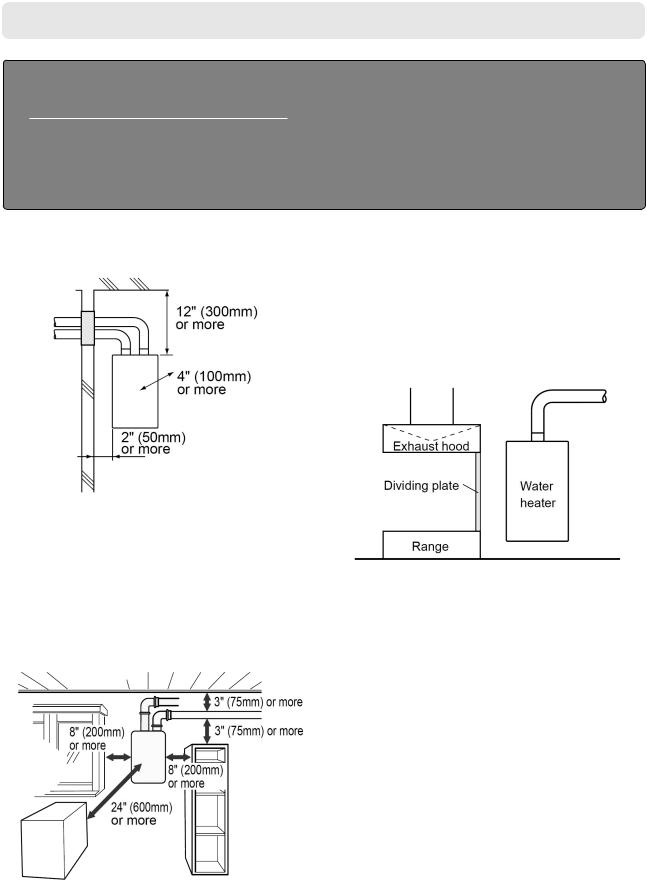
3-5. Installation Clearances
 WARNING
Before installing, check for the following:
Install in accordance with relevant building and mechanical codes, as well as any local, state or national regulations, or in the absence of local and state codes, to the National Fuel Gas Code ANSI Z223.1/
NFPA 54 – latest edition. In Canada, see Natural Gas and Propane Installation Code (CSA B149.1- latest edition.) for detailed requirements
Distance from combustibles
Maintain the following clearances from both combustible and non-combustible materials.
Securing of space for repair/inspection
If possible, leave 8" (200mm) or more on either side of the unit to facilitate inspection.
If possible, leave 24" (600mm) or more in front of the unit to facilitate maintenance and service if necessary.
If possible, leave 3" (75mm) or more above and below the vent pipe to facilitate inspection and repair if necessary
Cooking Equipment
<When the indoor air supply>
• If the unit will be installed in the vicinity of a permanent kitchen range or stove that has the possibility of generating steam that contains fats or oils, use a dividing plate or other measure to ensure that the unit is not exposed to air containing such impurities.
* The dividing plate should be of noncombustible material of a width greater than the water heater.
10
Chapter 3. – Safety Requirements |
Installation Clearances |
Clearance Requirements from Vent Terminations to Building Openings <When supplying combustion air from the outdoors (Direct Vent)>
|
Description |
US Direct Vent |
Canadian Direct Vent |
|
|
Installations 1 |
Installations 2 |
||
|
|
|||
A |
Clearance above grade, veranda, porch, deck, or balcony |
12 in (30 cm) |
12 in (30 cm) |
|
B |
Clearance to window or door that may be opened |
12 in (30 cm) |
36 in (91 cm) |
|
C |
Clearance to permanently closed window |
* |
* |
|
D |
Vertical clearance to ventilated soffit located above the terminal within |
* |
* |
|
a horizontal distance of 2 feet from the center line of the terminal |
||||
|
|
|
||
E |
Clearance to unventilated soffit |
* |
* |
|
F |
Clearance to outside corner |
* |
* |
|
G |
Clearance to inside corner |
* |
* |
|
|
Clearance to each side of center line extended above meter/regulator |
|
3 ft (91 cm) within a |
|
H |
* |
height 15 ft above the |
||
assembly |
||||
|
|
meter/regulator assembly |
||
|
|
|
||
I |
Clearance to service regulator vent outlet |
* |
3 ft (91 cm) |
|
J |
Clearance to non-mechanical air supply inlet to building or the combus- |
12 in (30 cm) |
36 in (91 cm) |
|
tion air inlet to any other appliance |
||||
|
|
|
||
|
|
3 ft (91 cm) above if |
|
|
K |
Clearance to a mechanical air supply inlet |
within 10 ft (3 m) hori- |
6 ft (1.83 m) |
|
|
|
zontally |
|
|
L |
Clearance above paved sidewalk or paved driveway located on public |
* |
7 ft (2.13 m) † |
|
property |
||||
|
|
|
||
M |
Clearance under veranda, porch, deck, or balcony |
* |
12 in (30 cm) ‡ |
1 In accordance with the current ANSI Z223.1 / NFPA 54 National Fuel Gas Code.
2 In accordance with the current CSA B149.1 Natural Gas and Propane Installation Code.
† A vent shall not terminate directly above a sidewalk or paved driveway that is located between two single family dwellings and serves both dwellings.
‡ Permitted only if veranda, porch, deck, or balcony is fully open on a minimum of two sides beneath the floor.
* Clearance in accordance with local installation codes and the requirements of the gas supplier. Clearance to opposite wall is 24 inches (60 cm).
11

Chapter 3. – Safety Requirements |
Installation Clearances |
Clearance Requirements from Vent Terminations to Building Openings <When supplying combustion air from the indoors (Non-Direct Vent)>
|
Description |
US Non-Direct 1 |
Canadian Non-Direct 2 |
|
A |
Clearance above grade, veranda, porch, deck, or balcony |
12 in (30 cm) |
12 in (30 cm) |
|
B |
Clearance to window or door that may be opened |
48 in (120 cm) below or to |
|
|
side of opening; 12 in (30 |
36 in (91 cm) |
|||
|
|
cm) above opening |
|
|
C |
Clearance to permanently closed window |
* |
* |
|
D |
Vertical clearance to ventilated soffit located above the terminal within |
* |
* |
|
a horizontal distance of 2 feet from the center line of the terminal |
||||
E |
Clearance to unventilated soffit |
* |
* |
|
F |
Clearance to outside corner |
* |
* |
|
G |
Clearance to inside corner |
* |
* |
|
H |
Clearance to each side of center line extended above meter/regulator |
|
36 in (91 cm) within a height |
|
* |
15 ft (4.57 m) above the |
|||
assembly |
||||
|
|
meter/ regulator assembly |
||
|
|
|
||
|
|
|
|
|
I |
Clearance to service regulator vent outlet |
* |
36 in (91 cm) |
|
J |
Clearance to non-mechanical air supply inlet to building or the combus- |
48 in (120 cm) below or to |
|
|
side of opening; 12 in (30 |
36 in (91 cm) |
|||
tion air inlet to any other appliance |
||||
|
cm) above opening |
|
||
|
|
|
||
K |
Clearance to a mechanical air supply inlet |
36 in (91 cm) above if with- |
6 ft (1.83 m) |
|
in 10 ft (3 m) horizontally |
||||
|
|
|
||
L |
Clearance above paved sidewalk or paved driveway located on public |
* |
7 ft (2.13 m) † |
|
property |
||||
|
|
|
||
M |
Clearance under veranda, porch, deck, or balcony |
* |
12 in (30 cm) ‡ |
1 In accordance with the current ANSI Z223.1 / NFPA 54 National Fuel Gas Code.
2 In accordance with the current CSA B149.1 Natural Gas and Propane Installation Code.
†A vent shall not terminate directly above a sidewalk or paved driveway that is located between two single family dwellings and serves both dwellings.
‡ Permitted only if veranda, porch, deck, or balcony is fully open on a minimum of two sides beneath the floor.
*Clearance in accordance with local installation codes and the requirements of the gas supplier. Clearance to opposite wall is 24 inches (60 cm).
12

Chapter 4. – Installation |
Securing to the wall |
4-1. Securing to the wall
 WARNING
CLEARANCES FOR SERVICE ACCESS
The water heater must be installed on a wall that can bear its weight.
If you try to install the heater on a wall which cannot support its weight, please reconsider.
The Water heater can be installed on any suitable internal wall (suitable sound proofing may be required when installing onto a stud partition wall).
1.Use the wall bracket to mark two locations where the anchor |
5. Lift up the Water Heater, rest the unit on the hooks provided |
bolts will be inserted.(Make sure that the wall bracket is level) |
on the wall bracket that is already mounted on the wall. |
2.Drill two holes with a 15/32"(12mm) size bit and insert the two anchor bolts into the holes with the threaded end out.
3. Place the wall bracket on the two anchor bolts.
4.Place washers and nuts on each anchor bolt and tighten. Make sure that it is leveled and it can support the weight of the Water Heater.
6. Locate the lower mounting bracket on the bottom of the |
9. Place the Water Heater back on the wall. (same as step 5) |
|||
Water Heater. The two screws and dry wall anchors will be |
10. Screw in the two screws into the dry wall anchors. |
|||
used to securer the bottom of the unit to the wall. |
|
|
|
|
|
|
|
|
|
|
|
|
|
|
|
|
|
|
|
|
|
|
|
|
Position the bracket securely to the wall.
Affix the screws into dry wall anchors.
7.Mark two holes. Then remove the Water Heater from the wall.
8.Drill two holes with a 17/64"(7mm) size bit.
Then insert the two dry wall anchors into the wall.
13

Chapter 4. – Installation |
Vent Pipe Installation |
4-2. Vent Pipe Installation (Indoor Installation Only)
 General Requirements
•Under normal conditions, this appliance will not produce an exhaust flue temperature in excess of 149°F (65°C) and schedule 40
PVC pipe may be used as the vent material.
•Make sure the vent system is gas tight and will not leak.
•Supporttheventpipewithhangersatregularintervalsasspecifiedbytheseinstructionsortheinstructionsoftheventmanufacturer.
•Do not common vent with other manufacturer’s water heaters or appliances. See page 37 to common vent with a Quick Connect
System.
•The total vent length including horizontal & vertical vent runs should be no less than 3' (0.9m).
•Donotstorehazardousorflammablesubstancesneartheventterminationandcheckthattheterminationisnotblockedinanyway.
 Venting With PVC or CPVC
This appliance can be vented with non cellular core plastic pipe materials as specified in the below table. Vent installations in Canada which utilize plastic vent systems must comply with ULC S636.
Item |
Material |
United States |
Canada |
|
|
|
|
|
Schedule 40 PVC |
ANSI/ASTM D1785 |
|
Exhaust Vent /Air Intake |
|
|
|
PVC-DWV |
ANSI/ASTM D2665 |
ULC S636 Certified |
|
|
|
|
|
|
Schedule 40 CPVC |
ANSI/ASTM F441 |
|
|
Materials Only |
||
|
|
|
|
Pipe Cement/Primer |
PVC |
ANSI/ASTM D2564 |
|
|
|
|
|
CPVC |
ANSI/ASTM F493 |
|
|
|
|
||
|
|
|
|
|
Note: Do Not Use Cellular Foam Core Pipe |
|
|
|
|
|
|
•Use only solid PVC or CPVC schedule 40 pipe. Cellular foam core piping is not allowed.
•InCanada,plasticventsystemsmustbecertifiedtoULCS636.Thecomponentsofthecertifiedventsystemmustnotbeinterchanged with other vent systems or unlisted pipe/fittings.
•In Canada, specified primers and glues of the ULC S636 certified vent system must be from a single system manufacturer and not intermixed with other system manufacturer’s vent system parts.
•PVC or CPVC pipe has been approved for use on this appliance with zero clearance to combustibles.
•Follow all general venting guidelines as outlined on this page.
•The pipe shall be installed so that the first 3' (0.9m) of pipe from the appliance flue outlet is readily accessible for visual inspection.
•When preparing and assembling the pipe, follow instructions as provided by the pipe manufacturer. In general, the following practices must be observed:
*Squarely cut all pieces of pipe.
* Remove all burrs and debris from joints and fittings.
* All joints must be properly cleaned, primed, and cemented. Use only cement and primer approved for use with the pipe material as outlined in the above table.
•All piping must be fully supported. Use pipe hangers at a minimum of 3' (0.9m) intervals. Do not use the water heater to support the vent piping.
•Abird screen must be installed on the vent terminations to prevent debris or animals from entering the piping.
14
 Loading...