


Owner’s Guide and
Installation Manual
Model N-084M-CA
WARNING: If the information in this manual is not followed exactly, a fire or explosion may result causing property damage, personal injury or death.
-Do not store or use gasoline or other flammable vapors and liquids in the vicinity of this or any other appliance.
-WHAT TO DO IF YOU SMELL GAS
•Do not try to light any appliance.
•Do not touch any electrical switch; do not use any phone in your building.
•Immediately call your gas supplier from a neighbor’s phone. Follow the gas supplier’s instructions.
•If you cannot reach your gas supplier, call the fire department.
-Installation and service must be performed by a qualified installer, service agency or the gas supplier.
CERTIFIED
R
Low NOx
Approved by SCAQMD
SAR8209-1
Thank you for purchasing this Noritz Gas Water Heater. Before using, please:
Read this manual completely for correct installation and operation instructions. Completely fill out the warranty registration card (included separately) and mail the detachable portion to Noritz America Corporation.
Keep this manual (and the remainder of the warranty registration card) where it can be found whenever necessary.
NORITZ America Corporation
*SAR8209 T*

Contents
|
Contents ........................................................................................................ |
2 |
|
|
Owner's Guide |
|
|
|
Important Safety Information ....................................................................... |
3 |
|
|
General Parts |
|
|
|
Main Unit .................................................................................................... |
8 |
|
|
Remote Controller .................................................................................... |
9 |
|
|
Initial Operation ........................................................................................... |
11 |
|
|
Setting and Using the Water Heater ........................................................... |
12 |
|
|
Flow Meter Alarm ......................................................................................... |
14 |
|
|
Muting the Remote Controller .................................................................... |
16 |
|
|
Preventing Damage from Freezing ............................................................ |
17 |
|
|
Regular Maintenance ................................................................................... |
19 |
|
|
Troubleshooting .......................................................................................... |
21 |
|
|
Follow-up Service ........................................................................................ |
25 |
|
|
Specifications .............................................................................................. |
26 |
|
|
External Outfitting ....................................................................................... |
27 |
|
|
Combustion Unit and Gas Route ............................................................... |
29 |
|
|
Hot-Water Feed Route ................................................................................. |
31 |
|
|
Electronic Control Unit ................................................................................ |
33 |
|
|
Electronic Control Unit, Remote Controller and Attached Set ................ |
34 |
|
|
Installation Manual ...................................................................................... |
35 |
|
|
1. |
Included Accessories ............................................................................ |
36 |
|
2. |
Optional Accessories ............................................................................ |
36 |
|
3. |
Quick Connect Multi System Installation ............................................ |
37 |
|
4. |
Before Installation ................................................................................. |
38 |
|
5. |
Choosing Installation Site .................................................................... |
38 |
|
6. |
Installation Clearances ......................................................................... |
40 |
|
7. |
Installation .............................................................................................. |
43 |
|
8. |
Vent Pipe Installation ............................................................................ |
44 |
|
9. |
Gas Piping .............................................................................................. |
47 |
|
10. |
Water Piping ........................................................................................... |
49 |
|
11. |
Plumbing Applications .......................................................................... |
50 |
|
12. |
Electrical Wiring .................................................................................... |
51 |
|
13. |
Maintenance ........................................................................................... |
55 |
|
14. |
Trial Operation ....................................................................................... |
55 |
|
15. |
Dimensions and Wiring Diagram ......................................................... |
56 |
|
16. |
Multi-System .......................................................................................... |
58 |
2 |
Remote Controller Installation Guide ........................................................ |
62 |
|
|
|
|
|
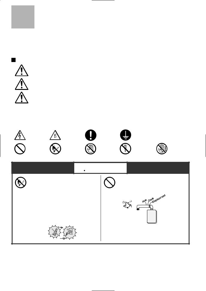
Important Safety Information-1
To prevent damage to property and injury to the user, the icons shown below will be used to warn of varying levels of danger.
Every indication is critical to the safe operation of the water heater and must be understood and observed.
Potential dangers from accidents during installation and use are divided into the following three categories. Closely observe these warnings; they are critical to your safety.
Icons warning of risk level
|
Danger |
|
Denotes content that may result in instantaneous fire, serious injury |
||||||||
|
|
and even death when ignored. |
|
|
|||||||
|
|
|
|
|
|
|
|||||
|
Warning |
Denotes content that may result in fire, serious injury and even |
|||||||||
|
death when ignored. |
|
|
||||||||
|
|
|
|
|
|
|
|||||
|
Caution |
|
Denotes content that may result in bodily injury and physical |
||||||||
|
|
damage when ignored. |
|
|
|||||||
|
|
|
|
|
|
|
|||||
|
Remarks |
|
The content following this icon is necessary to understand for safe |
||||||||
|
|
and easy use of this water heater. |
|
|
|||||||
|
|
|
|
|
|
|
|
|
|||
|
Other icons |
|
|
|
|
|
|
|
|||
|
|
|
|
|
|
|
|
||||
|
|
|
|
|
|
|
|
|
|
|
|
|
Electric |
|
High |
Be sure |
|
Ground. |
|
||||
|
Shock. |
|
|
|
Temperature. |
to do. |
|
|
|
||
|
|
|
|
|
|
|
|||||
|
|
|
|||||||||
|
|
|
|
|
|
|
|
|
|
|
|
|
Prohibited |
|
|
|
|
No flame. |
Don’t |
|
|
Don’t |
Don’t touch |
|
|
|
|
|
|
disassemble |
with a wet |
||||
|
|
|
touch. |
|
|
||||||
|
|
|
|
|
|
|
|
|
the equipment. |
hand. |
|
|
|
|
|
|
|
|
|
|
|
||
|
|
|
|
|
|
|
|
|
|
|
|
 Danger
If you detect a gas leak:
1.Do not try to light any appliance
2.Do not touch any electrical switch; do not use any phone in your building.
3.Immediately call your gas supplier from a neighbor’s phone. Follow the gas supplier’s instructions.
4.If you cannot reach your gas supplier, call the fire department.
Do not use the water heater if
the exhaust pipe is displaced, has holes, or is corroded.
3
Important Safety Information-2

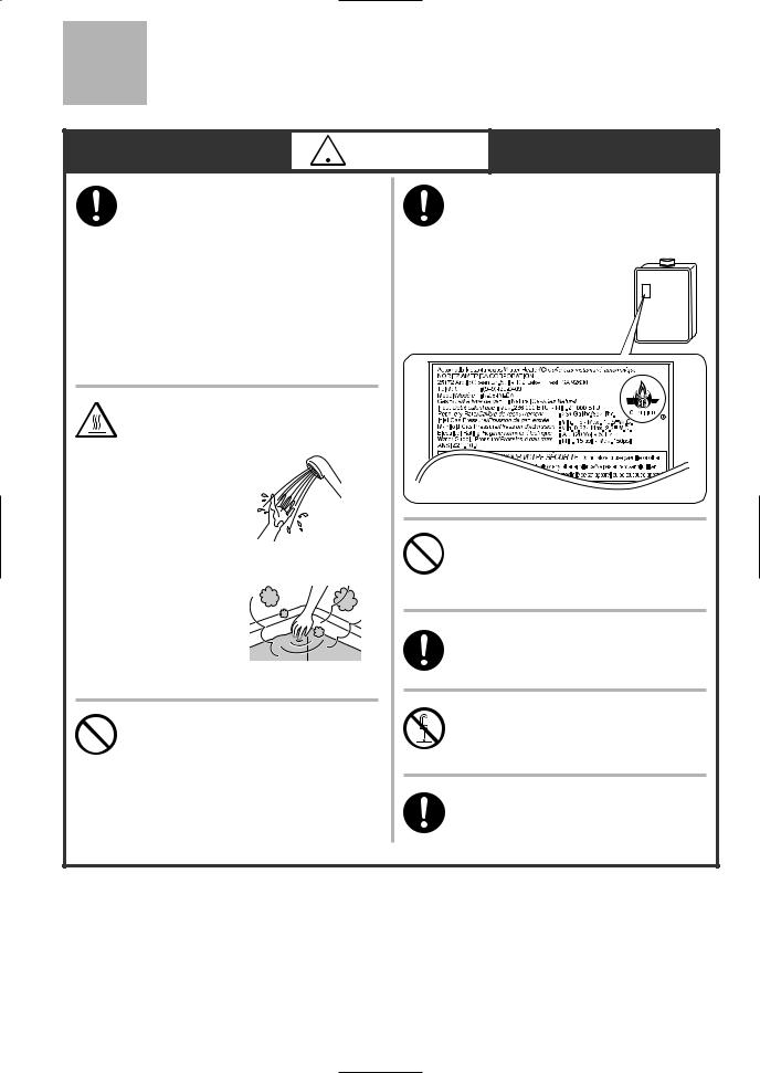
 Warning
If you detect abnormal combustion or abnormal odors, or during an earthquake, tornado or fire:
1.Turn off the hot water supply
2.Turn off the power to the water heater
3.Turn off gas and water at the main
4.Consult the nearest Noritz agent
Check the temperature of the running hot water before entering the shower.
Check the temperature before stepping into the bath tub.
Do not turn off the water heater or change the water temperature while someone is using.
Be sure the gas/power supplied matches the gas on the rating plate.
For Natural Gas
Do not allow small children to play unsupervised in the bathroom.
Do not allow small children to bathe unsupervised.
Consult the nearest Noritz agent if the water heater location needs to be changed.
Contact a qualified service technician for any necessary repairs, service or maintenance.
Contact Noritz before using with a solar pre-heater.
4
 Warning
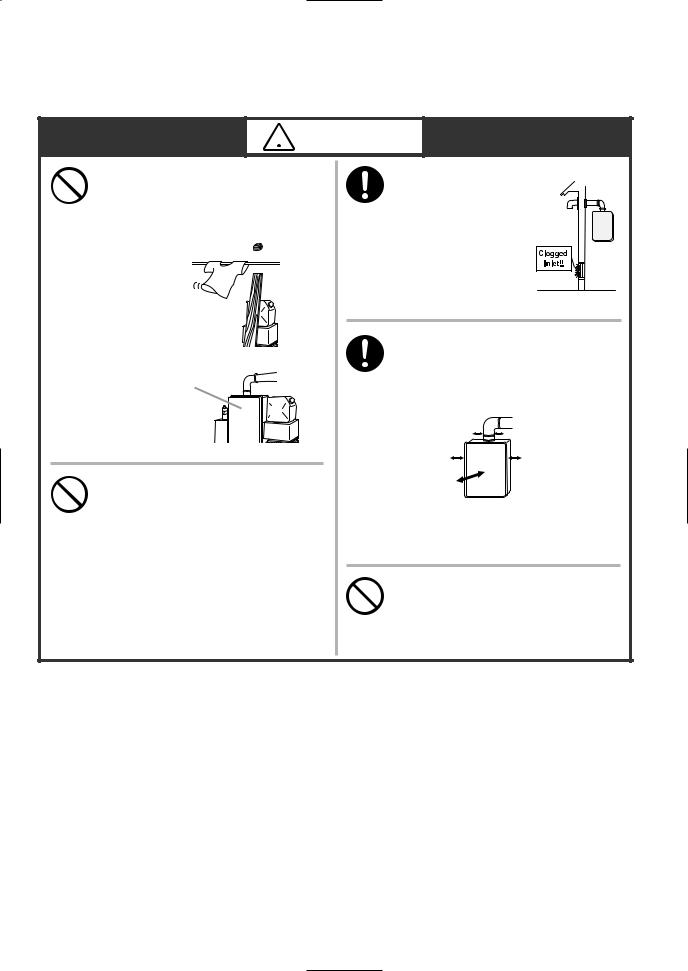
Do not place combustibles such as laundry, newspapers, oils etc. near the heater or the exhaust vent terminal.
Exhaust vent  terminal (indoor
installation)
Unit
Do not use combustible chemicals such as oil, gasoline, benzene etc. in the vicinity of the heater or the exhaust vent terminal.
[When installing indoors] Check the air supply vent for dust or obstructions.
Leave the proper clearance between the water heater and nearby objects (trees, timber, boxes with flammable materials etc.).
Min. 80mm(3") from vent pipe
Left side: |
|
Min.50mm (2") |
Right side: |
Front: |
Min.50mm (2" ) |
Sug. 600mm*(24"*) |
|
*Indicates suggested clearances for maintenance.
Do not place or use a spray can near the heater or the exhaust vent terminal.
5
Important Safety Information-3

 Caution
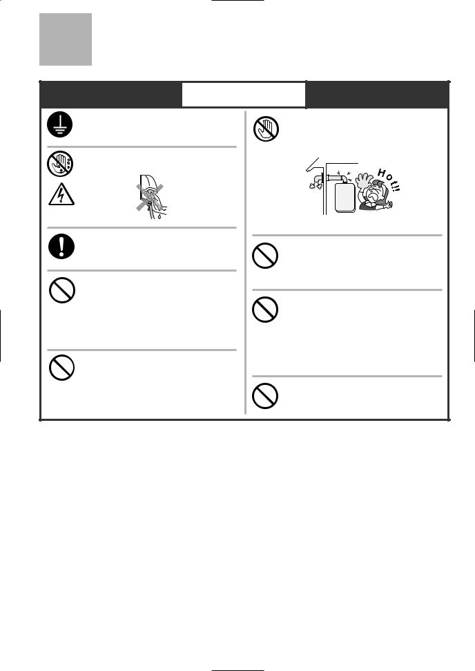
Be sure to electrically ground the unit.
Do not touch the power cord with wet hands.
Keep power cord free of dust.
Do not use a broken or modified power cord. Do not bind, bend or stretch power cords.
Do not scratch, modify, or subject them to impact or force.
Do not use the water heater for other than hot water supply, shower and bath.
Do not touch the exhaust vent pipe during or immediately after operation of the water heater.
Do not use hair spray or spray detergent in the vicinity of the
heater.
If this unit will be installed in a salon or other location where hair spray or aerosols will be used, locate the unit in a seperate area that is supplied with fresh air from outdoors.
Do not install in locations where excessive dust or debris will be
in the air.
6

Remark
Do not drink water that has been inside the unit for an extended period of time. Do not drink the first use of hot water from the unit in the morning.
Clean the filter on the water inlet as frequently as required by the quality of your local water.
Keep the area around the unit clean.
If boxes, weeds, cobwebs, cockroaches etc. are in the vicinity of the unit, damage or fire can result.
Do not install the equipment where the exhaust will blow on walls or windows.
Treat hard, acidic or otherwise impure supply water with approved methods to ensure full warranty coverage.
Problems resulting from scale formation are not covered by the warranty.
Check ignition during use and extinction after use.
This unit is only approved for installation up to 1300m (4500 ft.) above sea level.
For installations at higher elevations, contact Noritz America for Instructions.
Do not use parts other than those specified for this equipment.
Do not disassemble the remote controller.
Do not use benzene, oil or fat detergents to clean the remote controller.
This may cause deformation.
Do not get the remote controller wet.
Although it is water resistant, too much water can cause damage.
Do not splash water on the remote controller. Do not expose the remote controller to steam.
Do not locate the remote controller near stoves or ovens, this may cause damage or failure.
Preventing damage from freezing ( p.17)
p.17)
Damage can occur from frozen water within the device and pipes even in warm environments. Be sure to read below for appropriate measures. Repairs for damage caused by freezing are not covered by the warranty.
Take necessary measures to prevent freezing of water and leakage of gas when leaving the unit unused for long periods of time. ( p.18)
p.18)
If it is snowing, check the air inlet, exhaust gas vent and exhaust vent terminal for blockage.
7

General Parts
Main Unit
Indoor/Outdoor Wall Mounted, Power Vented Model
Flue Collar
Front Cover
Air Inlet
Water Drain Valve (with Water Filter)
(Inside Water Inlet) ( p.20)
p.20)
Pressure Relief Valve
Water Supply Valve
Gas Supply Valve
* The above illustration shows an example of installation.
The exact installation configuration may be slightly different.
8

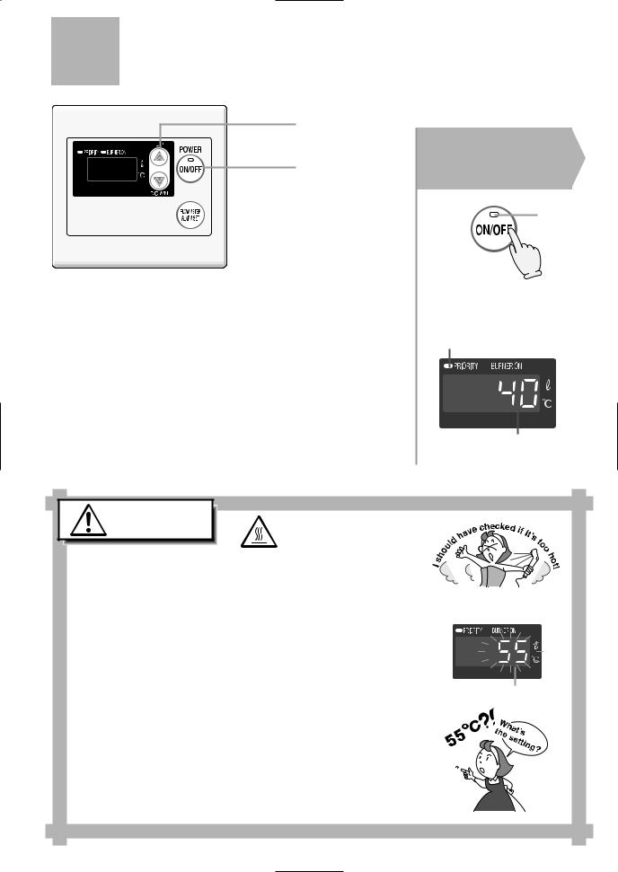
Remote Controller (RC-7646M-2)
Display
( next page)
Setting Buttons
For setting the hot water temperature, the flow meter alarm, and other settings.
Power On/Off Button
For turning the heater on and off.
Flow Meter Alarm Set Button
For setting the flow meter alarm.
( p.14 and 15)
*Before use, remove the protective sheet from the remote controller surface.
*The unit has been shipped from the factory with the remote controlset at 40°C (104°F).
9

Display
The illustration below shows the remote controller display. depends on how the water heater is set.
Burner On Indicator
Priority Indicator
When this indicator is lit, the hot water temperature can be set. ( p.13)
p.13)
What is actually displayed
Temperature Setting
(Ex.: 40°C (104°F))
Flow Meter Setting
The display will flash after hitting the flow meter alarm set button.
( p.15)
p.15)
Error Code
A number will flash if a failure occurs.
( p.24)
p.24)
10
Initial Operation
Before the first use of your water heater, make the following preparations.
Follow steps 1 through 4.
1 Open the water supply valve.
CLOSED |
OPEN |
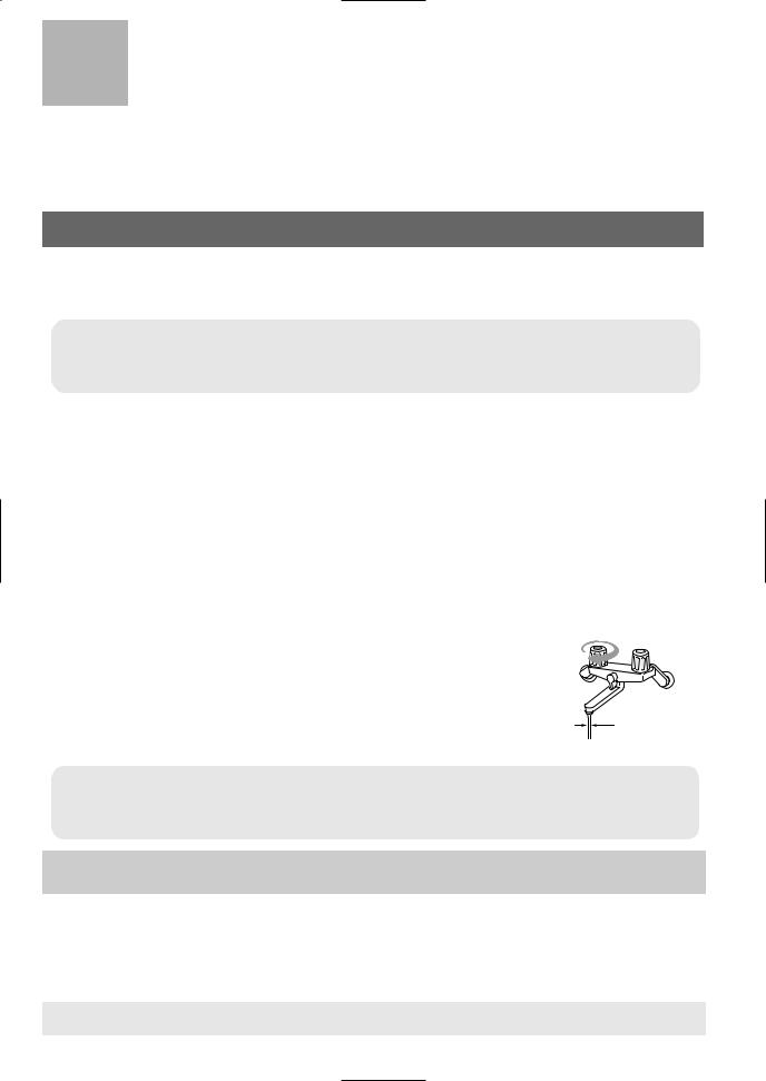
2 Open a hot water fixture to confirm that water is available, and then close the fixture again.
Hot water fixture
3 Open the gas supply valve.
4 Turn on the power.
11
How to Use
Setting and Using the Water Heater
2 |
(Starting with the Power Off) |
|
1 |
1 |
Press the Power |
|
|
|
|
|
On/Off Button. |
|
|
On |
|
The temperature will be |
|
|
displayed on the remote |
|
|
control thermostat. |
|
|
On |
|
Previous set temperature
(Ex.: 40°C (104°F))
Caution
To prevent scalding:
High Temperature
Temperatures above 55°C (131°F) can scald.
• Check the water temperature by hand before bathing or |
Remote Controller Display |
showering. |
|
• When setting the unit to 55°C (131°F) or higher, the temperature display will flash for 10 seconds as a high
temperature warning.
Flashes for 10 sec
• Take caution when using the unit again after setting to 55°C (131°F) or higher. Always check the set temperature before use.
• Do not allow anyone to change the water temperature while hot water is running.
12
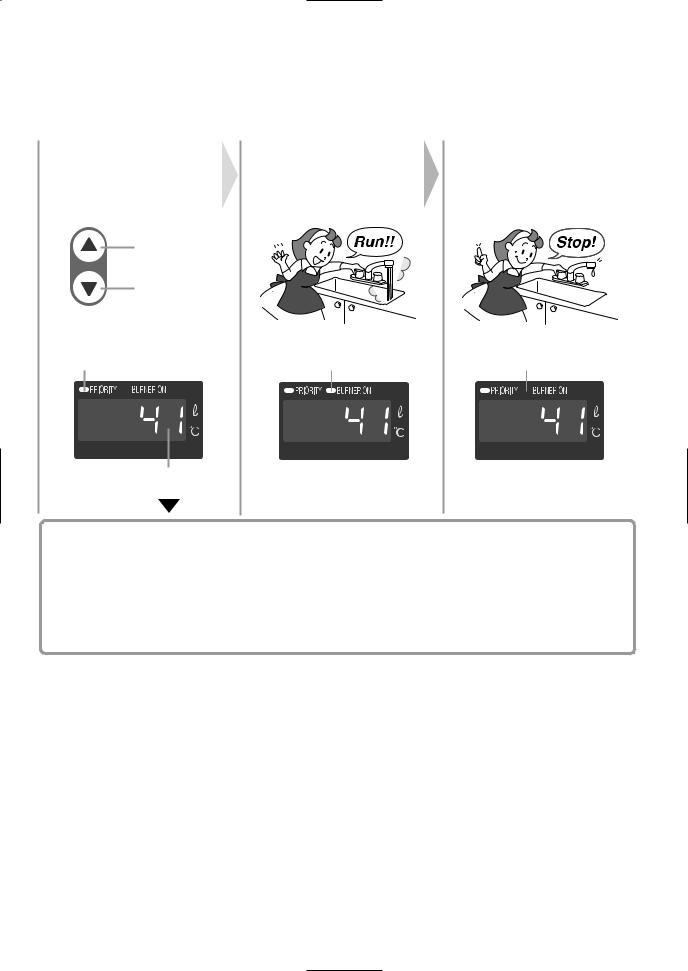
|
Set temperature. |
|
|
Turn on hot |
|
Turn off the hot |
2 |
Always check the |
) |
|
3 water. |
|
4 water. |
temperature setting |
|
|
||||
|
(before use. |
|
|
|
|
Hot
Cold
Check the indicator lights. |
On |
Off |
Water temperature
|
|
|
|
|
|
|
|
|
|
|
|
|
|
|
|
|
) |
|
|
|
|
|
|
|
|
|
The temperature settings below are examples. The temperature setting |
|
|
|
|
|
|
|
|||||||||||||||
(°C (°F): necessary depends on the usage, the length of piping and the time of year. |
|
|
|
|
|
|
|
|||||||||||||||||
37 |
38 |
39 |
40 |
41 |
42 |
43 |
44 |
|
45 |
46 |
47 |
|
48 |
50 |
55 |
|
60 |
65 |
70 |
75 |
80 |
83 |
|
|
(99) |
(100) |
(102) |
(104) |
(106) |
(108) |
(109) |
(111) |
(113) |
(115) |
(117) |
(118) |
(122) |
(131) |
(140) |
(149) |
(158) |
(167) |
(176) |
(181) |
|
||||
Faire la |
|
|
Douche, alimentation en eau chaude, etc. |
|
|
|
|
Température élevée |
|
|
|
|||||||||||||
vaisselle, etc. |
|
|
|
|
|
|
|
|
|
|||||||||||||||
|
|
|
|
|
|
|
|
|
|
|
|
|
|
|
|
|
|
|
|
|
|
|
||
|
|
|
|
|
|
|
|
|
|
|
|
|
|
|
|
|
|
|
|
|
|
|
||
*Initial factory setting is 40°C (104°F). |
|
|
|
|
|
|
If fixtures incorporate mixing valves, |
|||||||||||||||||
set the temperature higher than usual.
*For most residential applications, the recommended setting temperature is 50°C (122°F) or less. For applications that occasionally require a higher temperature setting, locate the remote controller in a convenient location ( p.62).
*Consult local codes for minimum operating temperatures.
13
How to Use
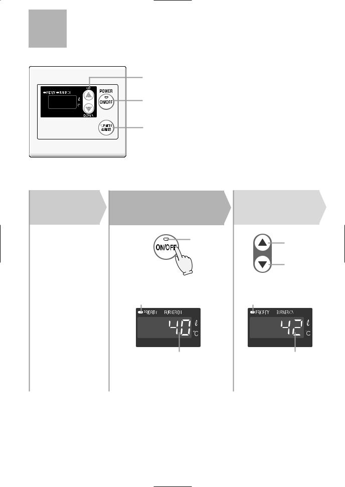
Flow Meter Alarm
2,3
1
3
(Starting with the power off)
Preparation |
Press the Power |
|
1 On/Off Button |
||
|
||
1. Plug the bath drain. |
On |
|
|
The temperature will be displayed on the remote control thermostat.
On
Previous set temperature (example:40°C(110°F))
Set temperature.
2 Always check (temperature setting )
before use.
Hot
Cold
Check the indicator lights.
Water temperature
14
An alarm will sound for ten seconds when the flow reaches the set level.
The water will continue to run unless it is manually turned off.
To set the flow meter alarm:
Water Temperature
(°C (°F): |
The temperatures settings below are only examples. The |
) |
|||||||||||
temperature setting necessary will depend on the usage, |
|||||||||||||
|
|
|
the length of piping and the time of year. |
|
|
|
|||||||
|
|
|
|
|
|
|
|
|
|
|
|
|
|
37 |
38 |
39 |
40 |
41 |
42 |
43 |
44 |
45 |
46 |
47 |
48 |
|
|
(99) |
(100) |
(102) |
(104) |
(106) |
(108) |
(109) |
(111) |
(113) |
(115) |
(117) |
(118) |
||
Warm |
|
Warmer |
|
|
|
Hot |
|
|
|
||||
|
|
|
|
|
|
|
|
|
|
|
|
|
|
* Initial factory setting: 40°C (104°F)
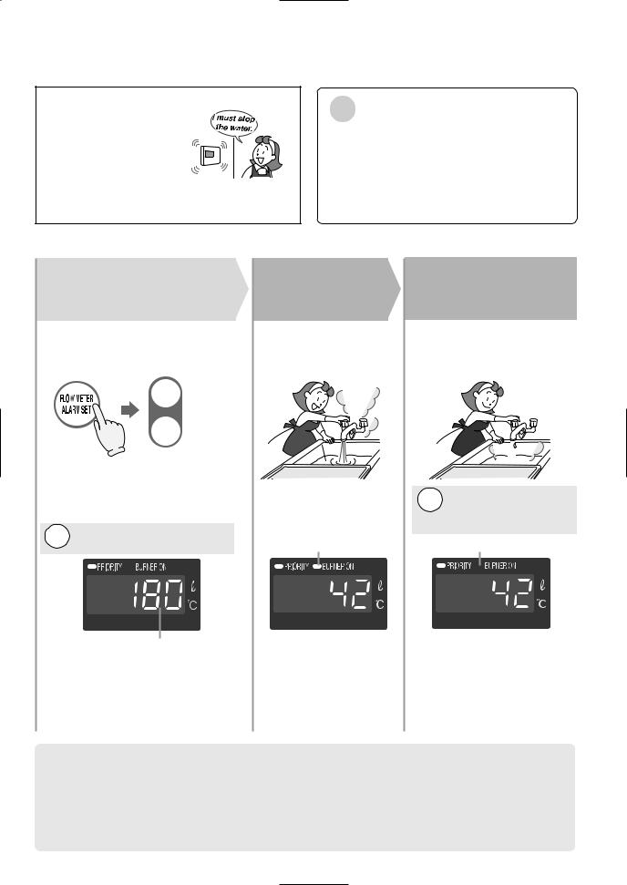
Adjust flow meter |
4 |
3 alarm setting. |
Press the flow meter alarm set button (the setting will flash on the display) and adjust with the setting buttons.

 Increase

 Decrease
Choose the flow meter alarm setting from the following options: 38 - 260 L (10 - 60 gallons) (In 20 L (5 gallons), 300 L (80 gallons), 340 L (90 gallons), 380 L (100 gallons), 990 L (262 gallons).)
Note: The alarm will not sound if it is set for 990L(262gallons).
Flow meter setting will be flashing (ex. 180 L (45 gallons))
*The level can only be adjusted while the indicator is flashing.
*After ten seconds, the remote
will again display the temperature.
Turn on hot water.
On
If the flow meter alarm is being used to indicate when a tub is full:
Turn off the hot 5 water when the
alarm sounds.
The alarm will sound when the set level has been reached. Stop the water.
Note: The alarm will not sound if it is set for
990 L (262 gallons.)
Off
•If any hot water is being used besides what is going into the tub, the alarm will sound before the tub is full.
•If there was water in the tub before the fill began, or if the water is not shut off manually when the alarm sounds, the tub may overflow.
•If there was water in the tub before the fill began, the temperature in the tub after it is full may be different from the temperature setting.
15

How to Use
Muting the Remote Controller
|
|
|
The remote controller will emit a sound |
|
|
|
|
|
|
|
when any button is pushed. This sound |
|
|
1 |
can be muted if it is desired. |
|
|
* Initial factory setting is with sound. |
|
|
|
|
|
|
|
|
|
With the remote controller 1 off, hold the Power On/Off
Button for five seconds.
Muted |
Sound |
No sound |
Tone sounds |
after 5 sec. |
after 5 sec. |
The flow meter alarm cannot be muted.
16
Preventing Damage from Freezing-1
|
|
Remarks |
|
|
|
|
|
|
* |
Damage can occur from frozen water within the device and pipes even |
|
|
|
|
|
||
|
|
|
|
|
in warm environments. Be sure to read below for appropriate measures. |
|
|
|
|
* |
Repairs for damage caused by freezing are not covered by the warranty. |
|
|
|
|
||
|
|
|
|
|
|
Freezing is prevented within the device automatically by the freeze-prevention heater
Freezing cannot be prevented when the power is disconnected.Do not remove the power plug from the wall outlet.
(Freezing will be prevented regardless of whether the operation switch is ON or OFF.)
*The freeze prevention heaters will not prevent the plumbing external to the unit from freezing. Protect this plumbing with insulation, heat tape or electric heaters, solenoids, or pipe covers. If there remains a freezing danger, contact the nearest Noritz agent.
Take the measures below for extremely cold temperatures*.
(outside temperature including wind chill factor less than -15°C (5°F))
This method can protect not only to the heater, but also to the water supply, water piping and mixing valves.
1.Turn the unit on with the Power Button on the Remote Controller.
2.Close the gas supply valve.
3.Open a hot water fixture and let it run for approx. 1 minute, and then check that the number 11 is flashing on the remote controller display.
*If multiple units are being used, drain one minute for each unit.
*It is possible that a different number may be displayed on the
remote controller, but as long as it is flashing, you may continue. |
Hot Water Fixture |
4. Partially close the hot water fixture, but keep a small amount of hot |
|
water running (400cc(0.1gallon)/minute or about 4mm (0.2”) thick). |
|
* If there is a mixing valve, set it to the highest level. |
|
* When linking multiple units, discharge water equivalent to |
|
400cc(0.1gallon)/minute per unit. |
4mm (0.2") thick |
|
5.The flow may become unstable from time to time. Check the flow 30 minutes later.
*Remember to set mixing valves and fixtures to their original levels before using the unit again to prevent scalding.
*If there is still a chance that the unit will freeze, drain the unit as on the next page.
If water will not flow because it is frozen:
1.Close the gas and water valves.
2.Turn off the power button.
3.Open the water supply valve from time to time to check whether water is running.
4.When the water is flowing again, check for water leaks from the equipment and piping before using.
If the heater or the piping is frozen, do not use the heater or it may get damaged.
17
Preventing Damage from Freezing-2
If the water heater will not be used for a long period of time, Drain the water.
Drain the water as follows:
|
Caution |
|
|
|
|
|
|
|
|
To avoid burns, wait until the equipment cools down |
|
|
|
|
|
|
|
|
|
|
|
|
before draining the water. The appliance will remain hot |
|
|
|
|
|
after it is turned off. |
|
High Temperature |
||||
|
|
||||
|
|
|
|
|
|
Drain water into a bucket to prevent water damage.
1. Close the gas valve.
2. (1) Turn the power on.
(2) Turn and leave open the hot water fixture for more than 1 minute and close.
*If multiple units are being used, drain one minute for each unit. |
Fixture |
|
* An 11 Error Code may appear on the remote control.
This is not a malfunction of the unit. Do not turn Power ON/OFF Button OFF.
3. Close the water supply valve, disconnect the electrical power supplied to the unit.
Do not touch with wet hands.
4. |
Fully open all hot water fixtures. |
Fixture |
|
|
|
||
5. |
Open all drain plugs and drain the water out |
|
|
|
of the unit. |
|
|
6. |
When the water is completely drained, replace all drain |
Drain Plugs |
|
|
plugs and close the hot water fixtures. |
|
|
Turning the Unit Back On
1.Check that all drain plugs are inserted.
2.Check that all hot water fixtures are closed.
3.Follow the procedure on p.11 “Initial operation”, steps 1 through 4.
18
Regular Maintenance-1
Periodic Inspection
|
Caution |
|
|
|
|
|
|
|
|
To avoid burns, wait until the equipment cools down |
|
|
|
|
|
|
|
|
|
|
|
|
before draining the water. The appliance will remain |
|
|
|
|
|
hot after it is turned off. |
|
|
High Temperature |
|||
|
|
|
|||
|
|
|
|
|
|
Check |
For laundry, newspaper, timber, |
Check |
For dust and soot in |
|
oil, spray cans and other |
|
the exhaust vent or |
|
combustible materials. ( p.5) |
|
exhaust vent terminal. |
Check |
For abnormal sounds |
Check |
For dust or debris in |
|
during operation. |
|
the air inlet. |
Check |
For abnormalities in |
|
|
|
external appearance, |
|
|
|
discoloration or flaws. |
|
|
Check |
For proper operation of |
|
|
|
pressure relief valve. |
|
|
Check |
For water leaks from the |
|
|
|
equipment and piping. |
|
|
Periodic Maintenance
Equipment
Wipe the outside surface with a wet cloth, then dry the surface. Use a neutral detergent to clean any stains.
Remote Controller
Wipe the surface with a wet cloth.
•Do not use benzene, oil or fatty detergents to clean the remote controller; deformation may occur.
•The remote controller is water resistant but not water proof. Keep it is dry as possible.
19
Regular Maintenance-2
Periodic Maintenance
Water Drain Valve (with Water Filter)
If the water drain valve (with water filter) is covered with debris, the hot water may not run smoothly, or the unit may put out cold water. Check and clean the filter as explained below.
*To avoid burns, wait until the equipment cools down before draining the water. The appliance will remain hot after it is turned off.
*Water will be discharged from the trap plug. Place a container, etc. to receive the discharged water.
1.Close the water supply valve.
2.Open all hot water fixtures.
3.Remove the inlet and outlet drain plugs (about 1L(0.3 gallons) will drain out)
4.Take the water drain valve (with water filter) out of the inlet. (See illustration to right).
5.Clean the water drain valve (with water filter) with a brush under running water.
6. Replace the water drain valve (with water filter). (Take care not to lose the packing.)
7. Close all hot water fixtures.
8.Open the water supply valve and check that water does not leak from the drain plugs or water drain valve (with water filter).
Inlet
Packing
 Drain Plug
(with filter)
Water Supply
Valve
Optional Maintenance
Water Heater Service Valves (IK-WV-2)
Hot Water
Service Valve
Pressure Relief Valve |
Cold Water |
|
Service Valve |
Drain |
Water Intlet |
|
Water Outlet |
||
|
*Isolator valve kits may be purchased as an accessory from Noritz (Part #IK-WV-2). They allow for one man full diagnostic testing and easy flushing of the system.
*The kit includes two full port isolation valves and a pressure relief valve for the hot side. Contact Noritz for more information.
20
Troubleshooting-1
Initial Operation
Unit does not attempt to ignite |
• |
Is water running? |
when water is running. |
• |
Check for reversed plumbing or crossed pipes. |
|
• |
Check the water drain valve filter. ( p.20 ) |
Unit attempts to ignite but fails |
• |
Reset unit and try again. There may be air in the gas line. |
|
• |
Have a professional check the gas supply pressure. |
|
|
|
Temperature
Hot water is not available when a fixture is opened.
•Are the gas and water supply valves fully open?
•Is the water supply cut off?
•Is the hot water fixture sufficiently open?
•Is the gas being cut off by the gas meter ?
(Can other gas devices such as stoves be used?)
•(For LP) Is there enough gas in the tank?
(Can other gas devices such as stoves be used?)
•Is the water drain valve filter clogged? ( p.20)
p.20)
•Is the power button turned on?
No water is available when |
• |
Is the water supply cut off? |
a fixture is opened. |
• |
Is the heater frozen? |
|
||
The hot water is not the correct |
• |
Is the hot water fixture sufficiently open? |
temperature. |
|
|
Water takes time to become hot |
• |
Have you allowed enough time for the cold water in the |
when turning the hot water fixture. |
|
pipes to drain out? |
The water is too hot. |
• Are the gas and water supply valves fully open? |
|
|
• |
Is the water temperature setting appropriate? |
|
|
( p.12 and p.13) |
|
• |
If the water supply temperature is high, it is possible |
|
|
for the temperature to be higher than the temperature |
|
|
set on the remote controller. |
|
• |
If only a small amount of hot water is demanded, it is |
|
|
possible for the temperature to be higher than the |
|
|
temperature set on the remote controller. |
|
• |
If the supply water goes through a solar pre-heating |
|
|
system, it is possible for the temperature to be higher |
|
|
than the temperature set on the remote controller. |
21

Troubleshooting-2
|
Temperature |
|
The water is not hot enough. |
• Are the gas and water supply valves fully open? |
|
• Is the water temperature setting appropriate? |
||
|
||
|
( p.12 and p.13) |
•If the amount of hot water required is very high, it is possible for the temperature to be lower than the temperature set on the remote controller.
Decrease the amount of water passing through the unit and the temperature should stabilize.
The water is cold when only a |
• |
The unit will not heat the water if the flow rate is less than |
|
2.7L(0.7 gallons) per minute. |
|
single fixture is open. |
|
|
|
|
Open the fixture more or open other fixtures so that a greater |
|
|
flow passes through the unit, and the unit should begin |
|
|
heating again. |
Fluctuations in hot water temperatures.
•Set water temperature at 48°C (118°F) to 50°C (122°F). This will allow you to use a higher flow of hot water thus meeting the minimum flow requirement of 2.7L/min. (0.7 gpm.)
•Clean the water filter of any debris ( p. 20)
Amount of Hot Water
The amount of hot water at a certain fixture is not constant.
•When hot water is demanded at other fixtures, the amount
available may be reduced. The maximum flow available from this unit is 32L/min. (8.4 GPM) at a 7°C (45°F) temp. rise.
•Pressure fluctuations and other plumbing conditions can cause the temperature and pressure at a fixture to be unstable, but it should stabilize after a short time.
•There are some types of hot water taps that discharge large volumes of hot water initially, but stabilize after time.
•To keep the temperature stable, the heater limits the amount of water that can flow through it to a small amount initially, but the amount increases over time.
The amount of hot water in the tub |
• When hot water is used for other fixtures while filling the |
|
is less/more than the set amount. |
|
bath tub, the tub will not fill as much. |
|
• |
If there is water in the tub already, or when filling is stopped |
|
|
and resumed, the tub will fill more. |
The flow meter alarm does not |
• The flow meter alarm is set to sound when hot water |
|
sound even when filled to the set |
|
is continuously discharged for the set volume of water. If mixing |
amount. |
|
valves are used, or if cold water is mixed with hot water at the |
|
|
fixture, the tub will fill more than the setting of the flow meter |
|
|
alarm. |
Amount of hot water available |
• |
Is the water drain valve filter clogged? ( p.20) |
has decreased over time. |
|
|
22

Remote Controller
The light on the power button does not come on.
•Has there been a power failure?
•Is the power connected properly?
The water temperature changes after a power failure or when the power is disconnected.
•The temperature setting and the flow meter alarm setting may both need to be reset after a power outage.
Sounds
The fan can be heard after operation is stopped.
A motor can be heard when turning the unit ON or OFF, when opening or closing a fixture, or after the unit has been running for a while.
•These noises indicate the proper operation of devices which are designed to let the unit reignite more quickly, and ensure the water temperature is stable.
|
|
Other |
The heater stops burning during |
• Are the gas and water supply valves fully open? |
|
operation. |
• Is the water supply cut off? |
|
|
• Is the hot water fixture sufficiently open? |
|
|
• Is the gas being cut off by the gas meter? |
|
|
|
(Can other gas devices such as stoves be used?) |
|
• (For LP) Is there enough gas in the tank? |
|
|
|
(Can other gas devices such as stoves be used?) |
White smoke comes out of the |
• |
This is normal. The white smoke is actually steam. |
exhaust vent on a cold day. |
|
|
|
• |
This is harmless. Small air bubbles appear as the |
The hot water is turbid.
water is heated and depressurized rapidly to atmospheric pressure.
Water leaks from the drain plugs on the outlet.
•When the unit is under very high pressure, water will leak from the drain plugs as a safety so that the unit is not damaged by the high pressure.
23
Troubleshooting-3
Other
The water appears blue or
The bath tub/wash-basin has turned blue
•This can be caused by a reaction of copper ions in the water with fat particles (furring). This is not a health risk, and the discloration of the tub or basin can be cleaned.
еГи·п\й¶ЗЗ® ннЗЗЗЗЗжЗ З¢ |
Check for an Error Code |
|
If there is a problem with the unit, a numerical error code will flash on the remote controller.
If this occurs, take appropriate measures as listed below. |
Flashing |
|
When an error code appears, the display and the operation light will flash together.
|
|
Remote Controller |
|
|
|
Error Code |
Cause |
Action |
|
Ignition error |
Check whether the gas valve is open. Press the power |
|
|
button to turn the unit off, open a hot water fixture, |
|
|
and turn the unit back on. If the flashing number |
|
|
doesn't return the problem is solved. |
|
Abnormal combustion, |
Have a professional check the gas supply pressure. |
|
low gas supply pressure |
Contact the nearest Noritz agent. |
|
Abnormal combustion |
Contact the nearest Noritz agent. |
|
|
|
Contact our sales agent if:
•Any other error code appears.
•An error code is indicated again after the above actions were followed.
•There are any other questions.
24
Follow-up Service
Requesting Service
First follow the instructions in the troubleshooting section (p.21 to p.24).
If the error is not corrected, contact our sales agent.
We will need to know:
The Model ................ |
(check the rating plate) |
*See p.4 for the location of the label |
|
Date of purchase ..... |
(see the warranty) |
Details of problem ... |
(flashing error codes, |
etc., in as much detail as possible)
Your name, address, and telephone number Desired date of visit
*A request for service may be rejected if the water heater is installed in a location where working on the unit may be dangerous. Contact a plumber.
Warranty
A warranty registration card is included separately.
Be sure that the plumber, date of purchase and other necessary items are filled in. Read the content carefully, and keep the warranty card in a safe place.
For repairs after the warranty period, there will be a charge on any service, and service will only be performed if the unit is deemed repairable.
Period of Time for Stocking Repair Parts
Noritz will stock repair and maintenance parts for this unit for a minimum of seven years after production has ceased.
Reinstallation
If you want to reinstall the appliance at a different location, confirm that the gas and power supply indicated on the rating plate are available at the new location. If you are not sure, consult the local utility company.
If you move to a region that uses a different type of gas, conversion and adjustment of the appliance will be necessary. This work must be performed by Noritz and will be charged for even during the warranty period.
25

|
Specifications |
• Specifications may be changed without prior notice. |
|
||
|
pressure, water supply, piping conditions, and water temperature. |
|
|||
|
|
|
• The capacity may differ slightly, depending on the water |
|
|
|
|
|
|
|
|
|
|
|
|
||
|
|
|
|
||
|
|
Specifications |
|
||
|
|
|
|
|
|
|
|
|
|
|
|
Item |
|
|
Specification |
|
|
Model Name |
|
|
N-084M |
|
|
Type |
Installation |
|
Indoor/ Outdoor, Wall Hanging |
|
|
|
|
Air Supply/Exhaust |
|
Power Vented |
|
Ignition |
|
|
Direct Ignition |
|
|
Operating Pressure |
|
|
15-150 PSI |
|
|
Minimum Flow Rate |
|
|
2.7 L/min. (0.7 GPM) |
|
|
Dimensions (Height) x (Width) x (Depth) |
|
615mm (24.2") x 465mm (18.3") x 239mm (9.4") |
|
||
Weight |
|
|
63 lbs. |
|
|
Water Holding Capacity |
|
|
1.1L (0.3 Gallon) |
|
|
Connection Sizes |
Water Inlet |
|
3/4" |
|
|
|
|
Hot Water Outlet |
|
3/4" |
|
|
|
Gas Inlet |
|
3/4" |
|
Power Supply |
Supply |
|
120 VAC (60Hz) |
|
|
|
|
Consumption |
|
NG:80W, LP:93W, Freeze Prevention 135W |
|
Materials |
Casing |
|
Zincified Steel Plate/Polyester Coating |
|
|
|
|
Flue Collar |
|
Stainless Steel |
|
|
|
Heat Exchanger |
|
Copper Sheeting, Copper Tubing |
|
Safety Devices |
|
|
Flame Rod, Thermal Fuse, Pressure Relief Valve, |
|
|
|
|
|
|
|
|
|
|
|
|
Lightning Protection Device (ZNR), |
|
|
|
|
|
Electric Leakage Prevention Device (GFCI), Overheat |
|
|
|
|
|
Prevention Device, Freezing Prevention Device, |
|
|
|
|
|
Fan Rotation Detector |
|
|
|
|
|
|
|
Accessories |
|
|
Remote Controller, Remote Controller Cord, |
|
|
|
|
|
|
Anchoring Screws |
|
|
|
|
|
|
|
Performance
Item |
|
Maximum Performance |
Minimum Performance |
Gas |
NG |
236,000 btuh |
21,000 btuh |
Consumption |
LP |
236,000 btuh |
21,000 btuh |
Maximum Hot Water Capacity |
7°C (45°F) Rise |
32L/min. (8.4 Gal./min.) |
|
Capacity Range |
|
2.7-32L/min. (0.7-8.4 Gal./min.) |
|
Temperature Settings |
|
37-50°C (99-122°F) (In 1°C intervals), |
|
|
|
55-80°C (131-176°F) (In 5°C intervals), 83°C |
|
|
|
(181°C ) (20 Options) |
|
Default Temperature Options |
|
50,55,60,80°C (122,131,140,176°F) |
|
|
|
(Original is 50°C (122°F)) |
|
|
|
|
|
26

External outfitting N-084M-CA
070
003
071
007
020
006
005
004
|
074 |
|
016 |
074 |
015 |
010 |
|
|
017 |
072 |
|
|
018 |
025 |
|
012 |
|
001
026
002
009
008
019
003
070 |
|
|
|
034 |
|
|
013 |
|
035 |
014 |
070 |
002 |
073 |
|
|
|
27

External outfitting N-084M-CA
Part Nos. |
|
|
|
|
Part Names |
Order Nos. |
Q'ty/unit |
|
|
|
|
|
|||
001 |
N-069M-CA Front SET-AS |
|
SKA7141 |
1 |
|||
002 |
Front packing S |
AAP |
|
AAPL015 |
2 |
||
003 |
Front packing L |
AAP |
|
AAPL017 |
2 |
||
004 |
Lamp seal plate |
|
DEC |
DECK008 |
1 |
||
005 |
Connection diagram label |
EJM |
EJMK001 |
1 |
|||
006 |
Caution label CA ENG |
EHU |
EHUK010 |
1 |
|||
007 |
Caution label 2 |
|
EAU |
|
EAUK004 |
1 |
|
008 |
Raintight seal plate BUB |
|
BUBK004 |
1 |
|||
009 |
Plug insulation sheet |
CRU |
CRUK002 |
1 |
|||
010 |
Exhause box |
|
EDM |
|
EDMF001 |
1 |
|
012 |
Exhause joint packing |
DHN |
DHNL003 |
1 |
|||
013 |
Wiring coupling BXK |
|
BXKA022 |
2 |
|||
014 |
Grommet |
|
CXP |
|
CXPA026 |
2 |
|
015 |
Exhaust sylinder packing |
EDL |
EDLL002 |
1 |
|||
016 |
Case top cover 2 |
|
EDL |
|
EDLA005 |
1 |
|
017 |
Case top cover |
EDM |
|
EDMA003 |
1 |
||
018 |
Case top packing |
|
EDM |
EDML001 |
1 |
||
019 |
Caution label CA1 |
|
EHU |
EHUK008 |
1 |
||
020 |
Caution label CA2 |
|
EHU |
EHUK009 |
1 |
||
025 |
Case |
EJM |
|
|
|
EJMA001 |
1 |
026 |
Air themistor-300 BWC |
|
BWCH003 |
1 |
|||
034 |
Junction box set |
EHU |
|
EHUA008 |
1 |
||
035 |
Junction box packing |
EHU |
EHUL002 |
1 |
|||
070 Cross recessed round-head collar N-tapping screw 4X8
071 Cross recessed truss type3 EVERTIGHT tapping screw with PW 4X12 072 Cross recessed round-head collar N-tapping screw 4X10
073 Cross recessed round-head collar type3 EVERTIGHT tapping screw 4X12 074 Cross & straight recessed truss type3 S TIGHT tapping screw 4X10
28

Combustion unit and gas route N-084M-CA
100
109
101 |
|
110 |
|
105 |
|
|
|
|
117 |
|
116 |
126 |
|
|
||
|
|
|
|
|
|
|
070 |
|
|
|
117 |
118 |
173 |
|
171 |
|
|
|
172 |
|
170 |
|
111 |
112 |
||
|
|||
114 |
115 |
|
070
119
175 175
121
127
102
103
131
104 |
070
070 |
132 |
129 |
|
072 |
128 176
070
141
125
070
173
122
121
120 |
123 |
172
171
124
172
073
29

Combustion unit and gas route N-084M-CA
Part Nos. |
|
|
|
|
|
Part Names |
Order Nos. |
Q'ty/unit |
|
|
|
|
|||||
100 |
Combustion tube set EAC SET-V |
SBP7302 |
1 |
|||||
101 |
Flame rod DLK SET-V |
|
|
|
SBA7506 |
1 |
||
102 |
Plug fixing plate(for N) |
DLK |
|
DLKL012 |
1 |
|||
103 |
Ignition plug Q(N) SET-V |
|
|
SBA7504 |
1 |
|||
104 |
Burner sensor DLK SET-V |
|
|
SBA7505 |
1 |
|||
105 |
Plug fixing plate(for N) |
DLK |
|
DLKC009 |
1 |
|||
109 |
Suction air joint packing |
DHN |
DHNL002 |
1 |
||||
110 |
Manifold set15 EDM SET-AS |
|
SBE7875 |
1<LPG> |
||||
|
Manifold set24 EDM SET-AS |
|
SBE7874 |
1<NGA> |
||||
111 |
Solenoid S16L CRU SET-AS |
|
SAQ7346 |
3 |
||||
112 |
Solenoid S24L CRU SET-AS |
|
SAQ7406 |
1 |
||||
114 |
O-ring S30 type 1A |
|
|
|
SAD6433 |
3 |
||
115 |
O-ring S-38 |
|
|
|
|
|
SAD6372 |
1 |
116 |
Manifold seal packing top |
CRP |
CRPL002 |
1 |
||||
117 |
Manifold seal packing side |
CRP |
CRPL004 |
2 |
||||
118 |
Manifold seal packing bottom |
CRP |
CRPL003 |
1 |
||||
119 |
Fan motor |
|
DKE |
|
|
DKEF030 |
1 |
|
120 |
Manifold pipe set |
EDM |
|
|
EDME006 |
1 |
||
121 |
O-ring P25.5 |
|
|
|
|
|
SAB1512 |
2 |
122 |
Gas mech S24DQ CRP SET-V |
|
SAQ7708 |
1 |
||||
123 |
O-ring JASO 2028A |
|
|
|
8590109 |
1 |
||
124 |
Gas fitting 20A SET |
EJH |
|
|
EJHE001 |
1 |
||
125 |
Mounting plate for burner case |
DLT |
DLTC001 |
1 |
||||
126 |
Main damper11 |
CRP |
|
|
CRPC052 |
1 |
||
127 |
Conduit R10 |
|
EDM |
|
|
EDMJ006 |
1 |
|
128 |
Igniter |
CRP |
|
|
|
CRPJ002 |
1 |
|
129 |
High-voltage cord 470 |
|
|
|
SAC1229 |
1 |
||
131 |
Mounting plate for igniter |
EAC |
EACC011 |
1 |
||||
132 |
Mounting plate for igniter |
DTJ |
DTJA015 |
1 |
||||
141 |
Bell-mouse φ44 |
|
CRU |
|
|
CRUC045 |
1<LPG> |
|
|
Bell-mouse φ48 |
|
CRU |
|
|
CRUC046 |
1<NGA> |
|
170Cross recessed round-head type3 EVERTIGHT tapping screw 5X16
171Cross recessed hexagon head machine screw M4X8
172Cross recessed round-head machine screw M4X8
173Cross recessed round-head N-tapping screw 4X8
175Cross recessed round-head SPAKmachine screw with guide M4X12
176Cross recessed round-head collar N-tapping screw 4X12
30
 Loading...