


 Loading...
Installation Manual |
NORITZ AMERICA |
|
CORPORATION |
TANKLESS GAS WATER HEATER
NR98-OD (Outdoor Installation)
Potential dangers from accidents during installation and use are divided into the following three categories. Closely observe these warnings, they are critical to your safety.
DANGER |
DANGER indicates an imminently hazardous situation which, |
|
if not avoided, will result in death or serious injury. |
|
|
|
|
|
WARNING |
WARNING indicates a potentially hazardous situation which, |
|
if not avoided, could result in death or serious injury. |
|
|
|
|
|
CAUTION |
CAUTION indicates a potentially hazardous situation which, |
|
if not avoided, may result in minor or moderate injury. |
|
|
|
|
|
WARNING: If the information in this manual is not followed exactly, a fire or explosion may result causing property damage, personal injury or death.
Prohibited |
Disconnect |
Ground |
Be sure to do |
|
Power |
||||
|
|
|


 CAUTION


Requests to Installers
•In order to use the water heater safely, read this installation manual carefully, and follow the installation instructions.
•Failures and damage caused by erroneous work or work not as instructed in this manual are not covered by the warranty.
•Check that the installation was done properly in accordance with this Installation Manual upon completion.
•After completing installation, please either place this Installation Manual in a plastic pouch and attach it to the side of the water heater (or the inside of the pipe cover or recess box if applicable), or hand it to the customer to retain for future reference. Also, be sure to fill in all of the required items on the warranty and to hand the warranty to the customer along with the Owner's Guide.
CERTIFIED
R
Low NOx
Approved by
SCAQMD
Accepted For Use
City of New York
SBA8348 Department of Buildings
MEA 19-03-E
Rev. 09/09
FOR USE IN RESIDENTIAL, COMMERCIAL, OR MANUFACTURED HOME APPLICATIONS.
Installation must conform with local codes, or in the absence of local codes, the National Fuel Gas Code, ANSI Z223.1/NFPA 54latest edition and/or CSA B149.1, Natural Gas and Propane Installation Code (NSCNGPIC).
When applicable, installation must conform with the Manufactured Home Construction and Safety Standard, Title 24 CFR, Part 3280 or the Canadian Standard CAN/CSA-Z240 MH Mobile Homes, Series M86.
Noritz America reserves the right to discontinue, or change at any time, the designs and/or specifications of its products without notice.
*SBA8348*
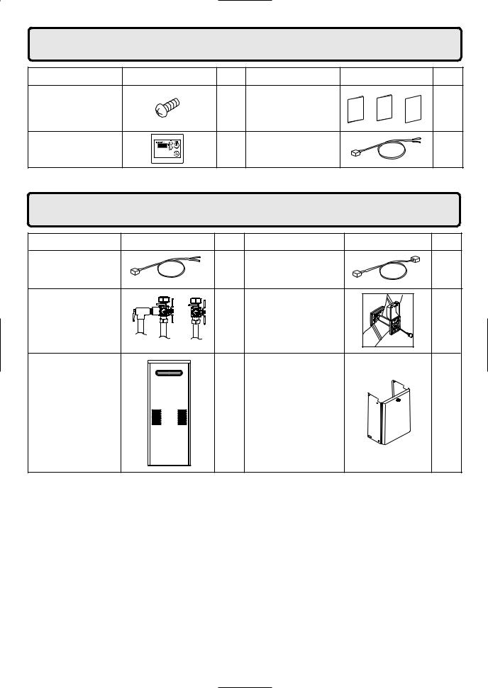
1. Included Accessories |
The following accessories are included with the unit. |
|
|||
Check for any missing items before starting installation. |
|||||
Part |
Shape |
Q’ty |
Part |
Shape |
Q’ty |
Cross Recessed |
|
3 |
Owner's Guide, Warranty, |
|
1 |
|
Installation Manual |
|
|||
Head Screw |
|
|
each |
||
|
|
(this document) |
|
||
|
|
|
|
|
|
Remote Controller |
|
1 |
Remote Controller |
|
1 |
(See p. 17) |
|
Cord (10ft) |
|
||
|
|
|
|
||
The accessories listed below are not
2. Optional Accessories included with the units, but may be necessary for installation.
Part |
Shape |
Q’ty |
Part |
Shape |
Q’ty |
Remote Controller |
|
1 |
Quick Connect Cord |
|
1 |
Cord (26ft) |
|
|
|||
|
|
|
|
|
|
Isolation Valves |
|
1 |
Remote Controller |
|
|
(includes pressure |
|
Outdoor |
|
1 |
|
relief valve) |
|
|
Junction Box |
|
|
|
|
|
|
|
Recess Box |
1 |
Pipe Cover |
1 |
|
(RB-700) |
(PC-2S) |
|||
|
|
2
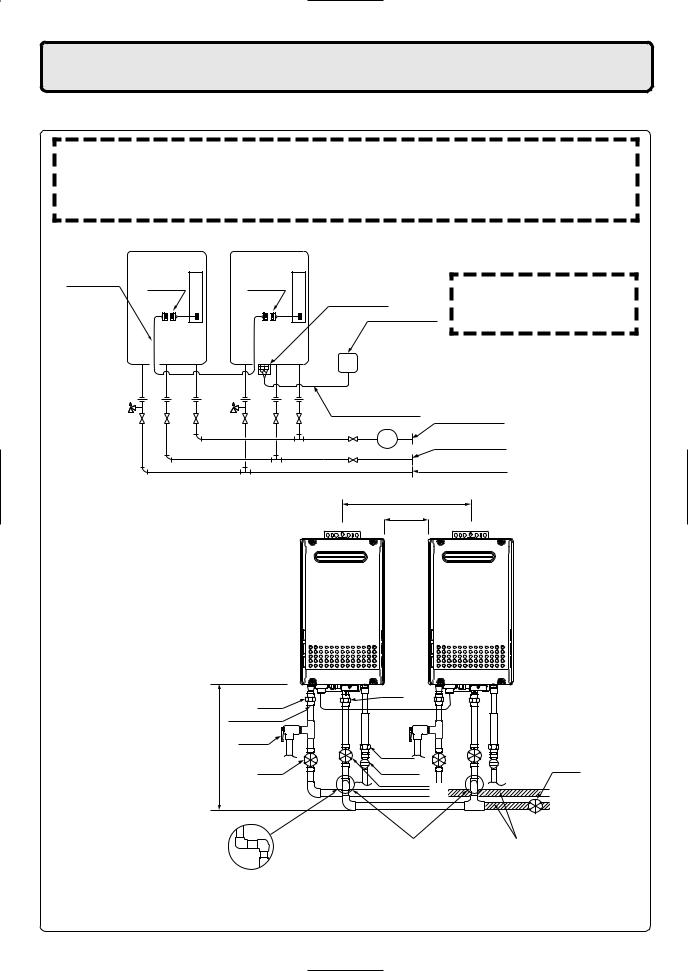
3. Quick Connect Multi System Installation
•The Quick Connect Multi System allows the installation of two units together utilizing only the Quick Connect Cord.
The Quick Connect Cord is 6 ft. long. Install the units 2-18" apart from each other to ensure the cord will be able to reach between the units. (See Typical Plumbing diagram).
(If the distance between the two units is too great, not only will the cord not be able to reach, but the water temperature may also become unstable because of the difference in pipe length between the two units).
System Diagram
Quick Connect |
Cord |
Cord |
|
Cord |
|||
Connector |
Connector |
||
|
Terminal Block
Remote Controller
*When connecting two units, use only a single remote controller.
Note: Connect the remote controller to only one of the units.
Remote Controller Cord
|
Gas Supply Piping |
G |
Cold Water Supply |
|
Hot Water |
Typical Plumbing
|
Union |
|
|
Quick Connect |
|
|
cord |
|
Make this distance as short as possible. |
Pressure |
|
Relief |
||
* The hot water temperature will |
Valve |
|
become unstable as the pipe |
Shutoff |
|
length increases. |
||
Valve |
||
|
Distance at center: 16-32 in.
Distance on sides
2-18 in.
Union
Union
Gas Valve
Shutoff Valve
Shutoff
Valve


 Hot Water
 Cold Water
Leave enough clearance around the plumbing to apply insulation. It will be necessary to add bends to the piping to ensure that this clearance is available.
Size the piping to allow for the maximum flow rates of the units.
•Insulate the hot water piping to prevent heat loss. Insulate and apply heating materials to the cold water supply piping to prevent heat loss and freezing of pipes when exposed to excessively cold temperatures.
3

4. Before Installation
Check the Gas

 WARNING
• |
Check that the rating plate indicates the |
NR98-OD |
|
|
correct type of gas. |
12,000 BTU |
|
|
|
199,900 BTU |
|
• |
Check that the gas supply line is sized for |
202 |
765 |
0.6 |
2.7 |
||
|
|
4.0 |
10.5 |
|
199,900 Btuh for this unit. |
15 |
150 |
|
|
2 |
|
Check the Power |
|
|
|
• The power supply required is 120VAC, at 60Hz. |
|
|
|
|
May result in fire or electric shock. |
|
|
Use Extreme Caution if Using With a Solar Pre-Heater
•Using this unit with a solar pre-heater can lead to unpredictable output temperatures and possibly scalding. If absolutely necessary, use mixing valves to ensure output temperatures do not get to scalding levels. Do not use a solar pre-heater with the quick-connect multi-system.

 CAUTION
Do Not Use Equipment for Purposes Other Than Those Specified
•Do not use for other than increasing the temperature of the water supply, as unexpected accidents may occur as a result.
Check Water Supply Quality
•If the water supply is in excess of 12 grains per gallon (200 mg/L) of hardness, acidic or otherwise impure, treat the water with approved methods in order to ensure full warranty coverage.
5.Choosing Installation Site
*Locate the appliance in an area where leakage from the unit or connections will not result in damage to the area adjacent to the appliance or to the lower floors of the structure. When such locations cannot be avoided, it is recommended that a suitable drain pan, adequately drained, be installed under the appliance. The pan must not restrict combustion air flow.

 DANGER
• This water heater is for outdoor installation only. Never install it indoors.
Do not enclose the termination with corrugated metal or other materials.
Indoor
This will cause carbon monoxide poisoning and a potential fire
hazard.
4
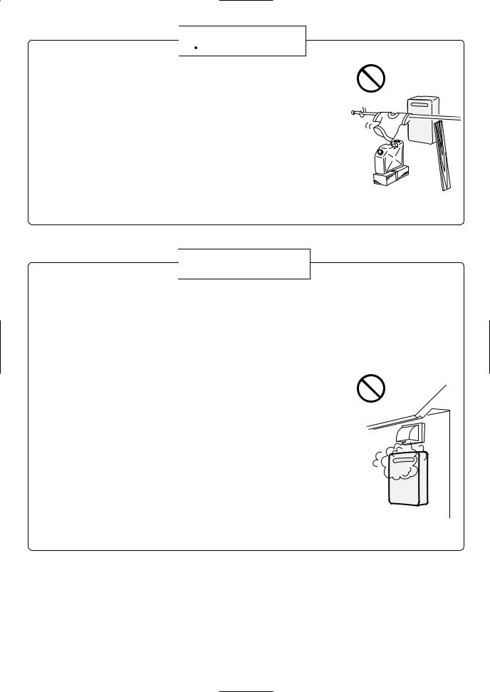

 WARNING
•Avoid places where fires are common, such as those where gasoline, benzene and adhesives are handled, or places in which corrosive gases (ammonia, chlorine, sulfur, ethylene compounds, acids) are present.
Using the incorrect voltage may result in fire or cracking. |
Prohibited |
|
|
• Avoid installation in places where dust or debris will accumulate. |
|
Dust may block the air-supply opening, causing the performance of the |
|
device fan to drop and incomplete combustion to occur as a result. |
|
• Avoid installation in places where special chemical agents (e.g., hair spray or spray detergent) are used.
Ignition failures and malfunction may occur as a result.
•Carbon Monoxide Poisoning Hazard. Do not install this water heater in a recreational vehicle or on a boat.

 CAUTION
•Install the water heater in a location where it is free from obstacles and stagnant air.
•Consult with the customer concerning the location of installation.
•Do not install the water heater near staircases or emergency exits.
•Do not install the water heater where the exhaust will blow on outer walls or material not resistant to heat. Also consider the surrounding trees and animals.
The heat and moisture from the water heater may cause discoloration of walls and resinous materials, or corrosion of aluminum materials.
• Do not locate the vent termination directed towards a window or any |
Prohibited |
other structure which has glass or wired glass facing the termination. |
|
•Install in a location where the exhaust gas flow will not be affected by fans or range hoods.
•Take care that noise and exhaust gas will not affect neighbors.
Avoid installation on common walls as the unit will make some operational noises while it is running.
•Avoid installation where the unit will be exposed to excessive winds.
•Before installing, make sure that the vent termination will have the proper clearances according to the National Fuel Gas Code (ANSI Z223.1).
State of California: The water heater must be braced, anchored or strapped to avoid moving during an earthquake. Contact local utilities for code requirements in your area or call: 1-866-766-7489 and request instructions.
The Commonwealth of Massachusetts:
1)The outdoor units (OD) can only be used if they are for summer use only.
2)The water heater can be used for hot water only and not in a combination of domestic and space heating.
5
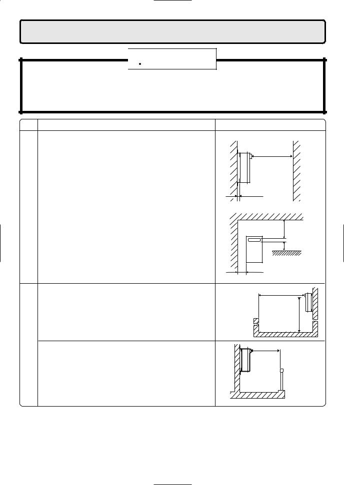
6. Installation Clearances

 WARNING
Before installing, check for the following:
Install in accordance with relevant building and mechanical codes, as well as any local, state or national regulations, or in the absence of local and state codes, to the National Fuel Gas Code ANSI Z223.1/NFPA 54 – latest edition. In Canada, see NSCNGPIC for detailed requirements.
Item
Required Clearances From Heater
installationof
Surrounding areathe
Check
•Maintain the following clearance from both combustible and non-combustible materials.
*( ) indicates the distance when installing a heat insulating board (incombustible material other than metal, with thickness of 0.1" or more) or "section of building effectively finished with incombustible material."
Note, however, that combustion failure may occur to the unit as exhaust gas reflects from the wall. Provide clearance of 24" or more in the front of the unit to facilitate inspection and repair.
•When installing the unit in a common side corridor, provide a clearance of 47" or more in front of the unit.
•Set the bottom edge of the exhaust port about 84" from the corridor floor.
•When installing the unit on a balcony, etc., secure an evacuation route of 24" or more in width.
•Provide clearance of 24" or more in front of the unit to facilitate inspection and repair. Do install the unit such as the wall of the second floor where the unit is out of reach.
|
Illustration |
|
|
combustible |
24" (12") |
combustible |
|
or more |
|||
|
|
||
|
0.4" or more |
|
|
combustible |
combustible |
|
|
combustible |
|||
36" or more 6" or more
6" or more
47" or more
about 84"
Handrail
common side corridor
24" or more
Handrail
balcony, etc.
6

Clearance Requirements from Vent Terminations to Building Openings
*All clearance requirements are in accordance with ANSI Z21.10.3 and the National Fuel Gas Code, ANSI Z223.1 and in Canada, in accordance with NSCNGPIC.
|
|
Vent Terminal |
|
Area Where Terminal |
|
|
|
|
|
||
|
|
Air Supply Inlet |
is Not Permitted |
||
|
|
|
|
||
|
|
|
|
||
|
Clearance |
Outdoor Installation |
|
||
|
(See p.8) |
|
|||
|
|
|
|||
A= |
Above grade, veranda, porch, deck,or balcony |
12" (12") |
|
||
|
|
||||
|
|
|
|
|
|
B= |
Window or door that may be opened |
12" (36") |
|
||
|
|
||||
|
|
|
|
|
|
C= |
Permanently closed window |
|
|
* |
|
|
Vertical clearance to ventilated soffit located above |
|
|
|
|
D= |
the terminal within a horizontal distance of 2 |
|
|
* |
|
feet from the center of the terminal |
|
|
|
||
|
|
|
|
|
|
|
|
|
|
|
|
E= |
Unventilated soffit |
|
|
* |
|
F= |
Outside corner |
|
|
* |
|
G= |
Inside corner |
|
|
* |
|
H= |
Each side of center line extended above |
3' within a height 15' above |
|
||
meter/regulator assembly |
meter/regulator assembly |
|
|||
|
|
||||
I= |
Service regulator vent outlet |
|
|
3' |
|
J= |
Nonmechanical air supply inlet or combustion air inlet |
12" (36") |
|
||
to any other appliance |
|
||||
|
|
|
|
||
K= |
Mechanical air supply inlet |
3' above if within 10' (6') |
|
||
L= |
Above paved sidewalk or paved driveway located on |
|
(7' ***) |
|
|
public property |
|
|
|||
|
|
|
|
|
|
M= |
Under veranda, porch, deck, or balcony |
* (12"- Canada Only****) |
|
||
|
|
||||
|
|
|
|
|
|
()= indicates clearances required in Canada
*Maintain clearances in accordance with local installation codes and the requirements of the gas supplier
***A vent shall not terminate directly above a sidewalk or paved driveway that is located between two single family dwellings and serves both dwellings.
****Permitted only if veranda,porch,deck,or balcony is fully open on a minimum of two sides beneath the floor.
7
Clearance Requirements from Vent Terminations to Building Openings
*All clearance requirements are in accordance with ANSI Z21.10.3 and the National Fuel Gas Code, ANSI Z223.1 and in Canada, in accordance with NSCNGPIC.
OpeningtoBuilding
ClearancesAny
into
Outdoor
WhenHeateris |
RecessBox |
VentClearances |
Installedina |
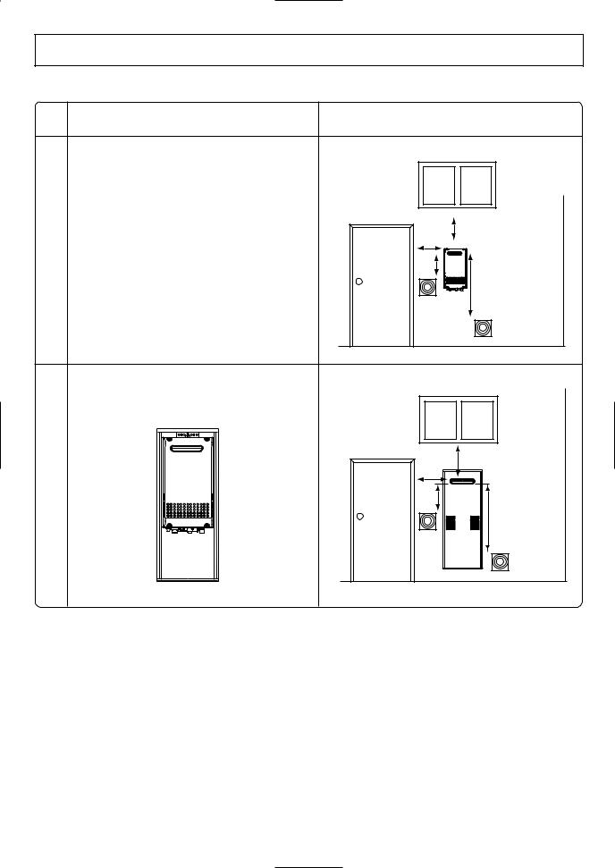
Maintain the following clearances to any opening in any building:
•1' below, 1' horizontally from, or 1' above any door, operable window, or gravity air inlet into any building.
3' above any forced air inlet within 10'.
•1' below, 1' horizontally from, or 1' above any door, operable window, or gravity air inlet into any building.
3' above any forced air inlet within 10'.
Illustration
1'
1'
1'
3'
1'
1'
1'
3'
(recess box installation with cover removed)
*For Installations in Canada, clearances are as follows: To windows, doors, & gravity air inlets: 36". To forced air inlets: 6'.
8
Loading...