

Noritz NH-2001-DV, NH-1501-DV Installation And Instruction Manual
NORITZ AMERICA
Installation and Instruction Manual
CORPORATION
GAS-FIRED DIRECT VENT BOILER
NH-2001-DV (Indoor Installation)
NH-1501-DV (Indoor Installation)
Potential dangers from accidents during installation and use are divided into the following three
categories. Closely observe these warnings, they are critical to your safety.
DANGER indicates an imminently hazardous situation which,
DANGER
if not avoided, will result in death or serious injury.
WARNING
CAUTION
WARNING indicates a potentially hazardous situation which,
if not avoided, could result in death or serious injury.
CAUTION indicates a potentially hazardous situation which,
if not avoided, may result in minor or moderate injury.
WARNING: If the information in this manual is not followed exactly, a fire or explosion may result
causing property damage, personal injury or death.
Prohibited
Disconnect
Power
Ground
Be sure to do
CAUTION
Requests to Installers
• In order to use the boiler safely, read this installation and instruction manual carefully, and follow
the installation instructions.
• Failures and damage caused by erroneous work or work not as instructed in this manual are not
covered by the warranty.
• Check that the installation was done properly in accordance with this installation and instruction
manual upon completion.
•
After completing installation, please either place this
plastic pouch and attach it to the side of the boiler or hand it to the customer. Also, be sure to fill in
all of the required items on the warranty and to hand the warranty to the customer along with the
User's information manual.
installation and instruction manual
in a
CERTIFIED
Low NOx
Approved by
SCAQMD
SAR8582-2
Rev. 09/07
Installation must conform with local codes, or in the absence of local codes, the
National Fuel Gas Code, ANSI Z223.1/NFPA 54- latest edition and/or CSA
B149.1, Natural Gas and Propane Installation Code (NSCNGPIC).
R
Where required by the authority having jurisdiction, the installation must conform to the Standard for Controls and Safety Devices for Automatically Fired
Boilers, ANSI/ASME CSD-1.
Noritz America reserves the right to discontinue, or change at any time, the
designs and/or specifications of its products without notice.
Noritz America Corporation
11160 Grace Avenue,
Fountain Valley, CA 92708
www.noritz.com
*SAR8582 C*
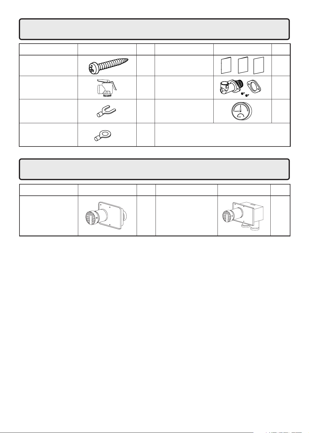
1.
Included Accessories
Tapping Screw
Safety Relief Valve
The following accessories are included with the
boiler in the inside of package.Check for any missing items before starting installation.
User's Information Manual,
Warranty, Installation and
5
Instruction Manual (this document)
Safety Relief Valve
1
Fitting and Gasket
Q’tyShapePartPart Shape Q’ty
1
each
1
Y terminal
Round terminal
2.
Optional Accessories
Flue Terminal
VT4-TL
Pressure & Temperature
4
11
1
Gauge
The accessories listed below are not
included with the boilers, but may be necessary for installation.
Flue Terminal
VT4-TS
1
Q’tyShapePartPart Shape Q’ty
1
2
Before Installation
3.
DANGER
Do Not Use Equipment for Purposes Other Than Those Specified
• The NH-2001-DV/ NH-1501-DV is a boiler to be used for space heating or indirect water
heating only. Do not use the hot water supplied by the boiler for drinking purposes.
• This boiler has a pressure rating of up to 150 psi, but it is designed to be used in a low pressure (15 psi) closed loop heating system. Use a 30 psi relief valve.
Checkup
• Once a year, check the fixing brackets, the air supply and exhaust pipes and the flue terminals
to see if they need to be replaced.
WARNING
Precautions on Vent Pipe Replacement
• The vent system will almost certainly need to be replaced when this appliance is being installed.
Use vent pipe that is listed to UL 1738 for Category III appliances for the exhaust venting. Category
III listed vent pipe is suggested for the air supply pipe also, but other materials may be acceptable.
Consult local codes.
* If Category III listed vent pipe is already installed, check for punctures, cracks or blockages and
consult with the vent pipe manufacturer before reusing.
Use Approved Vent Materials
• Use only vent materials that are listed to UL 1738 for Category III appliances for the exhaust venting
of this appliance.
Improper venting may result in fires, property damage or exposure to Carbon Monoxide.
Snow Precaution
• If this product will be installed in an area where snow is known to accumulate, protect the vent
termination from blockage by snow drifts or damage from snow falling off of roofs.
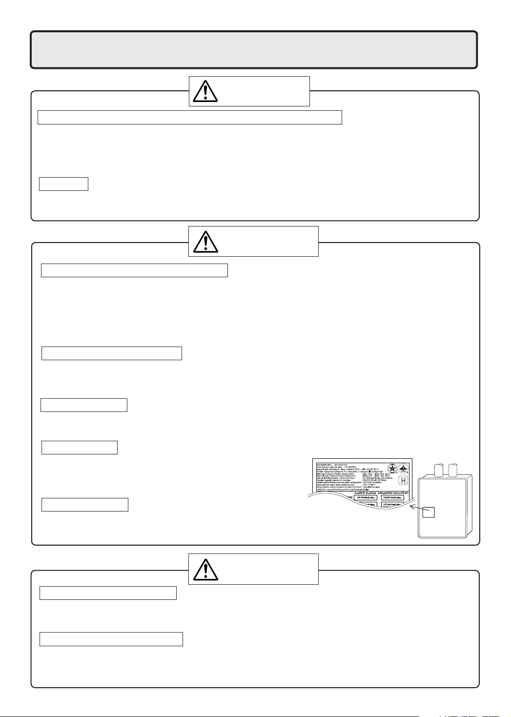
Check the Gas
• Check that the rating plate indicates the correct type of gas.
• Check that the gas supply line is sized for 199,900 Btuh for
the NH-2001-DV, or 150,000 Btuh for the NH-1501-DV.
Check the Power
• The power supply required is 120VAC, at 60Hz.
Using the incorrect voltage may result in fire or electric shock.
CAUTION
Check Water Supply Quality
• If the water supply is hard, acidic or otherwise impure, treat the water with approved methods in
order to ensure full warranty coverage.
Use the Specified Anti-Freeze
• When using anti-freeze, use Noritz approved anti-freeze only.
Using an anti-freeze other than one specified by Noritz could lead to leakage of fluid (water) or
clogging of pipes.
3
Choosing Installation Site
4.
* Locate the appliance in an area where leakage from the boiler or connections will not result in dam-
age to the area adjacent to the appliance or to the lower floors of the structure. When such locations
cannot be avoided, it is recommended that a suitable drain pan, adequately drained, be installed
under the appliance. The pan must not restrict combustion air flow.
* Install this boiler in a way that the constituent parts of the gas ignition system are protected from water
(water drops, spray, rain, etc.) during device operation and repair (circulator replacement, drain trap
or control device replacement, etc.).
DANGER
• Locate the vent terminal so that there are no obstacles around the termination and so that exhaust can't accumulate. Do not enclose the termination with corrugated metal or other materials.
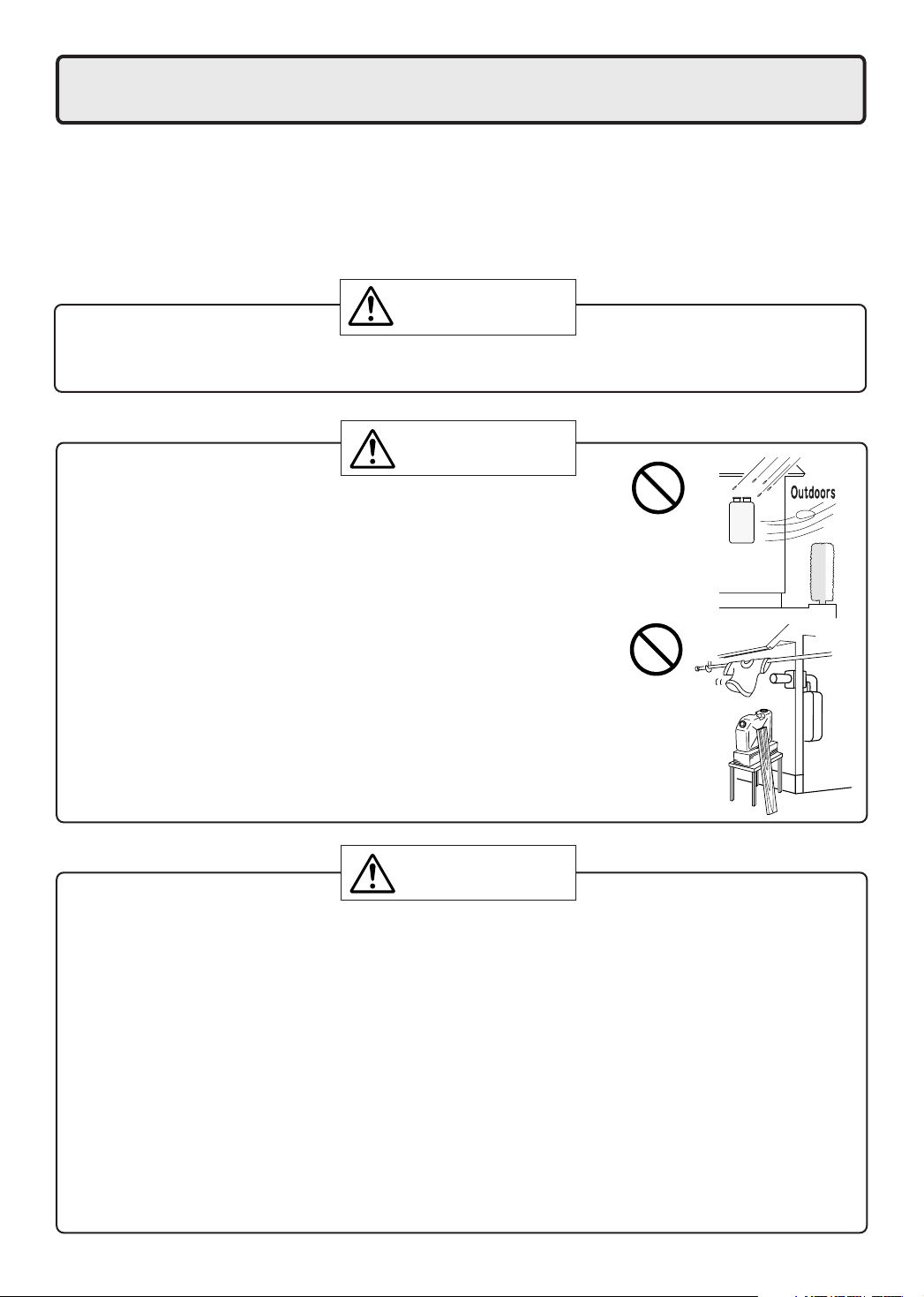
WARNING
• The boiler is designed for indoor installation only. Never install it
outdoors or in a bathroom, it may be damaged or a fire may be
caused.
• Avoid places where fires are common, such as those where
gasoline, benzene and adhesives are handled, or places in which
corrosive gases (ammonia, chlorine, sulfur, ethylene compounds,
acids) are present.
Using the incorrect voltage may result in fire or cracking.
Prohibited
• Avoid installation in places where special chemical agents
(e.g., hair spray or spray detergent) are used.
Ignition failures and malfunction may occur as a result.
• Carbon Monoxide Poisoning Hazard. Do not install this boiler in a
mobile home, recreation vehicle or on a boat.
Prohibited
CAUTION
• Consult with the customer concerning the location of installation.
• Install the boiler in an area that allows for the proper clearances to combustible and noncombustible construction. Consult the rating plate on the appliance for proper clearances.
• Avoid installation in places where dust or debris will accumulate.
Dust may block the air-supply opening, causing the performance of the device fan to drop and
incomplete combustion to occur as a result.
• Do not install the boiler in a place where it may be threatened by falling objects, such as under
shelves.
• The boiler must be installed in a place where supply and exhaust pipes can be installed as
directed.
• Do not install the boiler where the exhaust will blow on outer walls or material not resistant to
heat. Also consider the surrounding trees and animals.
The heat and moisture from the boiler may cause discoloration of walls and resinous materials,
or corrosion of aluminum materials.
4
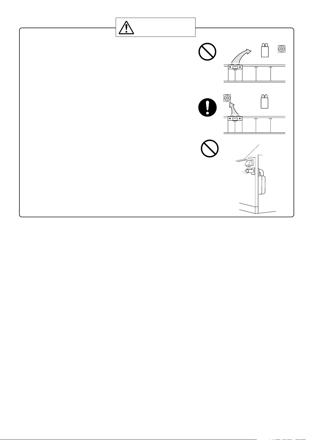
CAUTION
• Avoid installation above gas ranges or stoves.
• Avoid installation between the kitchen fan and stove. If oily
fumes or a large amount of steam are present in the installation location, take measures to prevent the fumes and steam
from entering in the equipment.
• Install in a location where the exhaust gas flow will not be
affected by fans or range hoods.
• Take care that noise and exhaust gas will not affect neighbors.
• Before installing, make sure that the exhaust flue termination
will have the proper clearances according to the National Fuel
Gas Code (ANSI Z223.1).
• Installation must conform with local codes, or in the absence
of local codes, the National Fuel Gas Code, ANSI Z223.1/
NFPA 54- latest edition and/or CSA B149.1, Natural Gas and
Propane Installation Code (NSCNGPIC).
Prohibited
Be sure to do
Prohibited
State of California: The boiler must be braced, anchored or strapped to avoid moving during an earthquake. Contact local utilities for code requirements in your area or call: 1-866-766-7489 and request
instructions.
For Venting Manufacturers Requirements, see websites or phone numbers listed below:
Noritz N-Vent www.noritz.com
Protech FastNSeal & W2 www.protechinfo.com
HeatFab SafTVent www.heat-fab.com
Z-Flex Z-Vent www.z-flex.com
Flex-L StaR-34 1-800-561-1980
5
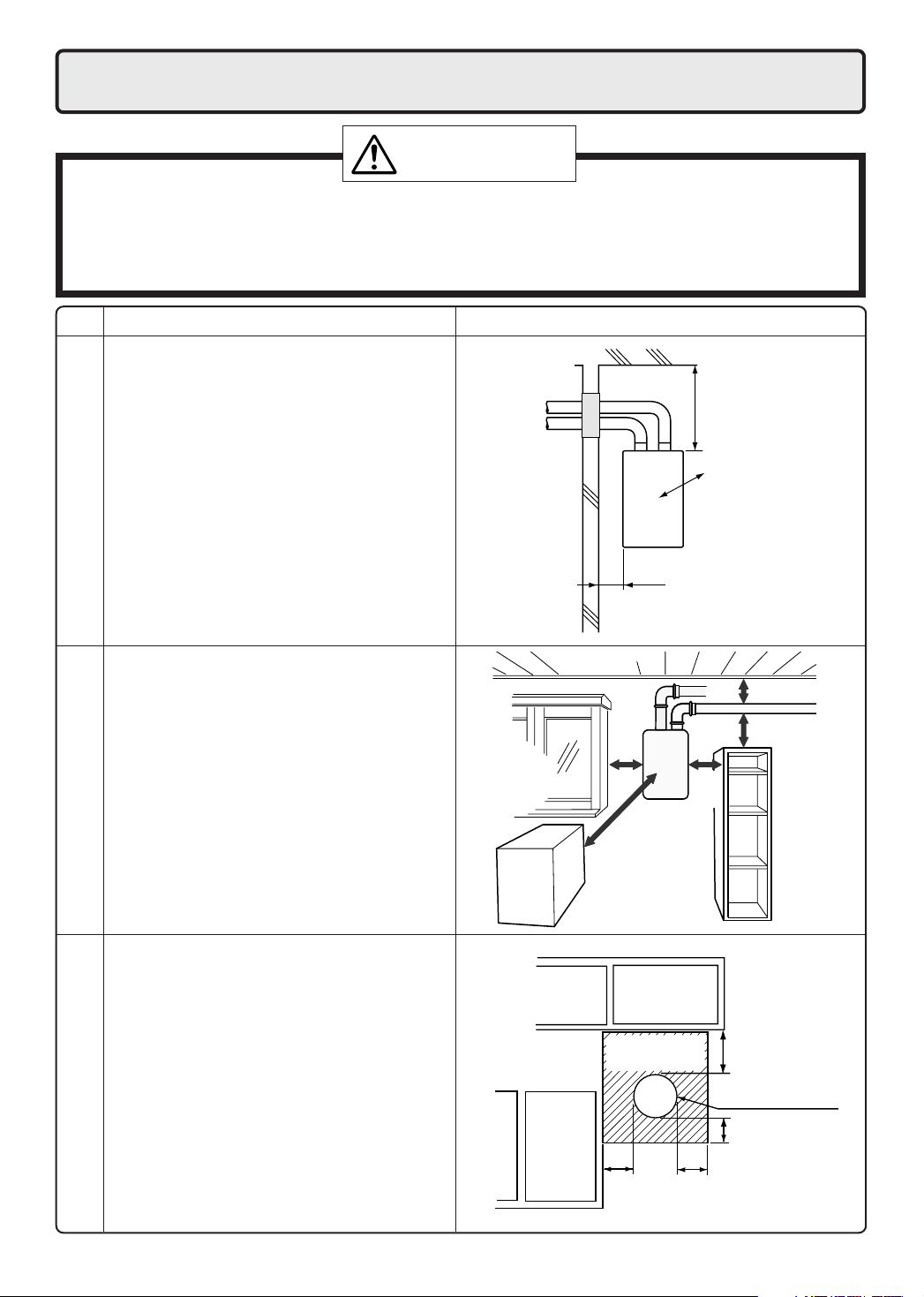
5. Installation Clearances
WARNING
Before installing, check for the following:
Install in accordance with relevant building and mechanical codes, as well as any local, state or
national regulations, or in the absence of local and state codes, to the National Fuel Gas Code ANSI
Z223.1/NFPA 54 – latest edition. In Canada, see NSCNGPIC for detailed requirements.
Item
• Maintain the following clearances
from both combustible and
non-combustible materials.
Distance from combustibles
• If possible, leave 8" or more on either
side of the unit to facilitate inspection.
• If possible, leave 24" or more in front of
the unit to facilitate maintenance
and service if necessary.
• If possible, leave 3" or more above and
below the vent pipe to facilitate inspec-
repair/inspection
tion and repair if necessary
Securing of space for
Check Illustration
2" or
more
Distance from
the side
8" or
more
8" or
more
24" or
more
12"
or
more
4" or
more
3"
or more
3"
or more
• There must be a clearance of 24" or
more in front of the Flue terminal.
• This restriction will not be applied to an
area where an effective shield makes a
clearance of 24" or more in front of the
exhaust outlet.
into Any Building
Outdoor Clearances to Opening
6
There must be no
building opening
within this area.
12"
or more
12" or
more
12" or
more
Flue terminal
12" or
more

Clearance Requirements from Vent Terminations to Building Openings
* All clearance requirements are in accordance with ANSI Z21.13 and the National Fuel Gas Code,
ANSI Z223.1 and in Canada, in accordance with NSCNGPIC.
Clearance
Above grade, veranda, porch, deck,
A=
or balcony
Window or door that may be opened
B=
Permanently closed window
C=
Vertical clearance to ventilated soffit
located above the terminal within a
D=
horizontal distance of 2 feet from the
center of the terminal
Unventilated soffit
E=
Outside corner
F=
Inside corner
G=
Each side of center line extended
H=
above meter/regulator assembly
Service regulator vent outlet
I=
Nonmechanical air supply inlet or
J=
combustion air inlet to any other
appliance
Mechanical air supply inlet
K=
Above paved sidewalk or paved
L=
driveway located on public property
Under veranda, porch, deck, or
M=
balcony
Vent Terminal
Air Supply Inlet
12" (12")
12" (36")
*
*
*
*
*
3' within a height 15' above
meter/regulator assembly
3'
12" (36")
3' above if within 10' (6')
(7' ***)
* (12"- Canada Only****)
Area Where Terminal
is Not Permitted
()= indicates clearances required in Canada
*Maintain clearances in accordance with local installation codes and the requirements of the gas supplier
***A vent shall not terminate directly above a sidewalk or paved driveway that is located between two
single family dwellings and serves both dwellings.
****Permitted only if veranda,porch,deck,or balcony is fully open on a minimum of two sides beneath the floor.
7
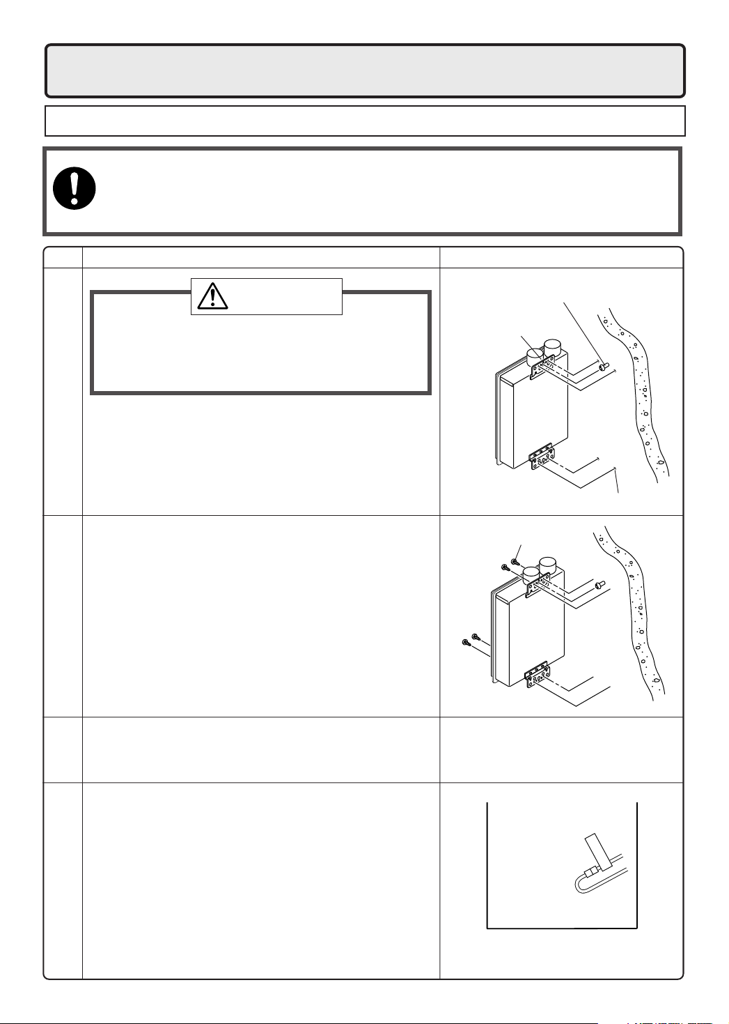
6. Installation
Securing to the wall
• The weight of the device will be applied to the wall. If the strength of the wall is not sufficient, reinforcement must be done to prevent the transfer of vibration.
• Do not drop or apply unnecessary force to the device when installing. Internal parts may
Be sure to do
be damaged and may become highly dangerous.
• Install the boiler on a vertical wall and ensure that it is level.
Item
CAUTION
• When installing with bare hands, take caution to
not inflict injury.
• Be careful not to hit electrical wiring, gas, or water
piping while drilling holes.
1. Drill a single screw hole, making sure to hit a stud.
2. Insert and tighten the screw and hang the boiler by
the upper wall mounting bracket.
Locating Screw Holes
3. Determine the positions for the remaining four screws
(two for the top bracket and two for the bottom), and
remove the boiler.
4. Drill holes for the remaining four screws.
5. Hang the boiler again by the first screw, and then
insert and tighten the remaining four screws.
6. Take waterproofing measures so that water does
not enter the building from screws mounting the
Mounting
device.
IllustrationCheck
Location of Screw Hole
Mounting Bracket
(upper)
Locating Screw Holes
Tapping Screw
•Make sure the boiler is installed securely so that it
will not fall or move due to vibrations or earthquakes.
Structure
• If this boiler is being installed at an elevation of 2,000
ft. (610m) or higher, disconnect the connector labeled
"High Elevation Disconnect" as illustrated on the right.
This connector is located inside the unit.
• Disconnect power to the boiler before disconnecting
this connector. Failure to perform this step will result in
a "733" code displayed on the boiler control panel and
a cease in operation. If this occurs, disconnect, then
Above 2,000 ft.
reconnect power to the boiler to reset the system.
Installations at Elevations
8
DISCONNECT
HIGH ELEVATION
Vent Pipe Installation
7.
Vent Terminal Installation
•
Follow the installation instructions included with the vent terminal. It is suggested that the appliance be vented horizontally
through a sidewall. If a vertical vent termination is required, it must follow the requirements of this section (p.9-12).
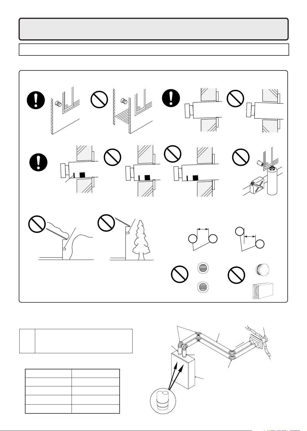
Vent Terminal Installation Precautions
• Do not install the vent terminal indoors • Install the vent terminal with a downward slope
• Install with the proper length protruding through the wall
Proper installation. The
red line can be seen,but
the red rectangle cannot
be seen from the outside.
Avoid installing the terminal where obstacles will block it
•
Vent terminal
Snow
drift
• Do not install the vent terminals vertically in-line.
Do not cover the vent terminal with any type of
protective screen or enclosure. In-line or blocked
terminals can cause abnormal combustion resulting
in undesired performance from the boiler.
not far
enough
Note the following vent terminal installation requirements
upward
slope
Gasoline
Gas
12" or more
Vent terminal
Vent terminal
Tree
downward
slope
Avoid storing hazardous
•
objects near the terminal
too far
• Clearance from vent terminal.
If multiple boilers are installed, terminals
must be separated by 12" or more in a plain
view regardless of the vertical clearance.
12" or more
Vent terminal
Vertical position not allowed.
Vent terminal models
• Use only the following models of Noritz
vent terminals with this boiler.
VT4-TL
•
Vent
•
Vent terminal size variations are listed in the table below.
Choose the model according to the wall thickness required.
VT4-TS
•
terminal
Model
VT4-TL-5 3.5" to 5.1"
VT4-TL-8 5.1" to 8.3"
VT4-TL-14 8.3" to 14.6"
VT4-TL-27 14.6" to 27.2"
(for long vent runs)
(to be installed directly
on top of the appliance)
Wall thickness (in.)
Vent system installation example
Elbows
Intake pipe
Straight pipe
Vent terminal
sloping down
Exhaust
pipe
Elbow
Boiler
Use a listed Category III vent adapter
to connect the flue collar to the vent
system. Use Category III vent pipe
for the entire length of the exhaust pipe.
9

Be sure to do
WARNING
CARBON MONOXIDE POISONING
Follow all vent system requirements in accordance with relevant local or state regulation,
or, in the absence of local or state code, in the U.S. to the National Fuel Gas Code ANSI
Z233.1/NFPA 54 – latest edition, and in Canada, in accordance with NSCNGPIC.
Venting Precautions
• Use 4" diameter Category III vent pipe.
• Maximum vent length
Number of 90
degree elbows
4
3
2
1
Maximum
Vent Length
39'
45'
51'
57'
• Exceeding the maximum vent length is dangerous and may result in bad combustion.
• If possible,don ’t install the vent pipe through any
enclosed areas. If necessary,consult the pipe
manufacturer ’s instructions for clearances.
•
Install the vent terminal so that all exhaust is directed to and all intake air is taken from outdoors.
• In the Commonwealth of Massachusetts a carbon monoxide detector is required for all side
wall horizontally vented gas fuel equipment.
Please refer to Technical Bulletin TB 010606 for
full installation instructions.
• Do not store hazardous or flammable substances near the vent terminal .
• Slope the intake and exhaust pipes downwards
1/4" for every 12" towards the termination.
• Use only UL listed Category III venting products.
• Connect the vent pipe firmly so that it will prevent
exhaust gases from leaking.
• Steam or condensed water may drip out of the
vent terminal. Dispose of this condensed water
according to local codes and in order to prevent
injury or property damage.
• If this product will be installed in an area where
snow is known to accumulate, protect the vent
termination from blockage by snow drifts or damage from snow falling off of roofs.
• Support the vent pipe with hangers at intervals
as required by the vent pipe manufacturer ’s installation instructions.
• Install the vent terminal so that it is easily
accesible for maintenance both from the indoors
and the outdoors.
• If the vent terminal will be installed higher than
the boiler, make the vertical section directly
above the boiler as short as possible,and slope
down to the terminal. Do not have another vertical section after the horizontal section begins.
• Make the vertical pipe as short as possible.
• Follow the vent pipe manufacturer's installation
instructions.
• Maintain the same vent pipe diameter all the
way to the end.
• Maintain the following clearances for the
exhaust pipe to combustibles:
Manufacturer and Enclosed Unenclosed
Product Hor. Vert. Hor. Vert.
Noritz N-Vent 4" 1" 1"
Protech FasNSeal 4" 3" 3"
10" (sides)
15"(top)
6"(bottom)
8" (sides)
12"(top)
4"(bottom)
Protech FasNSeal W2 6" 4" 3" 3"
HeatFab SafTVent 6" 6" 2" 2"
Z-Flex Z-Vent 8" 4" 1" 1"
Flex-L-StaR-34 8" 4" 1" 1"
These clearances are subject to change.
Refer to the UL listing for the proper clearances.
10
• Do not common vent or connect more than
one appliance to this venting system.
Appliance Adapters
• Use the following adapters to connect the
boiler to the venting system.
Manufacturer and
Product
Part No.
Protech FasNSeal FSAA4
HeatFab SafTVent 9401RYPK
Z-Flex Z-Vent 2SVWA04
Flex-L StaR-34 SRASPSA4
• Terminate at least 12"above grade or snow line
• Terminate at least 7'above a public walkway
•Use a condensation drain if necessary
 Loading...