

Noritz NH199-DV, NH150-DV Installation And Instruction Manual

NORITZ AMERICA
Installation and Instruction Manual
CORPORATION
GAS-FIRED DIRECT VENT BOILER
NH199-DV (Indoor Installation)
NH150-DV (Indoor Installation)
Potential dangers from accidents during installation and use are divided into the following three
categories. Closely observe these warnings, they are critical to your safety.
DANGER indicates an imminently hazardous situation which,
DANGER
if not avoided, will result in death or serious injury.
WARNING
CAUTION
WARNING indicates a potentially hazardous situation which,
if not avoided, could result in death or serious injury.
CAUTION indicates a potentially hazardous situation which,
if not avoided, may result in minor or moderate injury.
WARNING: If the information in this manual is not followed exactly, a fire or explosion may result
causing property damage, personal injury or death.
Prohibited
Disconnect
Power
Ground
Be sure to do
CAUTION
Requests to Installers
• In order to use the boiler safely, read this installation and instruction manual carefully, and follow
the installation instructions.
• Failures and damage caused by erroneous work or work not as instructed in this manual are not
covered by the warranty.
• Check that the installation was done properly in accordance with this installation and instruction
manual upon completion.
•
After completing installation, please either place this
plastic pouch and attach it to the side of the boiler or hand it to the customer. Also, be sure to fill in
all of the required items on the warranty and to hand the warranty to the customer along with the
User's information manual.
installation and instruction manual
in a
SBA8383
Rev. 09/09
Approved by
CERTIFIED
R
Accepted For Use
City of New York
Department of Buildings
MEA 20-07-E
Noritz America Corporation
11160 Grace Avenue,
Fountain Valley, CA 92708
www.noritz.com
Low NOx
SCAQMD
Installation must conform with local codes, or in the absence of local codes, the National Fuel Gas Code, ANSI
Z223.1/NFPA 54- latest edition and/or CSA B149.1, Natural Gas and Propane Installation Code (NSCNGPIC).
Where required by the authority having jurisdiction, the installation must conform to the Standard for Controls and
Safety Devices for Automatically Fired Boilers, ANSI/
ASME CSD-1.
Noritz America reserves the right to discontinue, or
change at any time, the designs and/or specifications of its
products without notice.
*SBA8383*

1.
Included Accessories
Tapping Screw
Safety Relief Valve
5
1
The following accessories are included with the
boiler in the inside of package.Check for any missing items before starting installation.
Q’tyShapePartPart Shape Q’ty
User's Information Manual,
Warranty, Installation and
Instruction Manual (this document)
Safety Relief Valve
Fitting and Gasket
1
each
1
Y terminal
Round terminal
2.
Optional Accessories
Flue Terminal
VT4-TL
4
11
1
Pressure & Temperature
Gauge
The accessories listed below are not
included with the boilers, but may be necessary for installation.
Flue Terminal
VT4-TS
1
Q’tyShapePartPart Shape Q’ty
1
2
Before Installation
3.
DANGER
Do Not Use Equipment for Purposes Other Than Those Specified
• The NH199-DV/ NH150-DV is a boiler to be used for space heating or indirect water heating
only. Do not use the hot water supplied by the boiler for drinking purposes.
• This boiler has a pressure rating of up to 150 psi, but it is designed to be used in a low pressure (15 psi) closed loop heating system. Use a 30 psi relief valve.
Checkup
• Once a year, check the fixing brackets, the air supply and exhaust pipes and the flue terminals
to see if they need to be replaced.
WARNING
Precautions on Vent Pipe Replacement
• The vent system will almost certainly need to be replaced when this appliance is being installed.
Use vent pipe that is listed to UL 1738 for Category III appliances for the exhaust venting. Category
III listed vent pipe is suggested for the air supply pipe also, but other materials may be acceptable.
Consult local codes.
* If Category III listed vent pipe is already installed, check for punctures, cracks or blockages and
consult with the vent pipe manufacturer before reusing.
Use Approved Vent Materials
• Use only vent materials that are listed to UL 1738 for Category III appliances for the exhaust venting
of this appliance.
Improper venting may result in fires, property damage or exposure to Carbon Monoxide.
Snow Precaution
• If this product will be installed in an area where snow is known to accumulate, protect the vent
termination from blockage by snow drifts or damage from snow falling off of roofs.
Check the Gas
• Check that the rating plate indicates the correct type of gas.
•Check that the gas supply line is sized for 199,900 Btuh for
the NH199-DV, or 150,000 Btuh for the NH150-DV.
Check the Power
• The power supply required is 120VAC, at 60Hz.
Using the incorrect voltage may result in fire or electric shock.
NH199-DV
CAUTION
Check Water Supply Quality
• If the water supply is hard, acidic or otherwise impure, treat the water with approved methods in
order to ensure full warranty coverage.
Use the Specified Anti-Freeze
• When using anti-freeze, use Noritz approved anti-freeze only.
Using an anti-freeze other than one specified by Noritz could lead to leakage of fluid (water) or
clogging of pipes.
3

Choosing Installation Site
4.
* Locate the appliance in an area where leakage from the boiler or connections will not result in dam-
age to the area adjacent to the appliance or to the lower floors of the structure. When such locations
cannot be avoided, it is recommended that a suitable drain pan, adequately drained, be installed
under the appliance. The pan must not restrict combustion air flow.
* Install this boiler in a way that the constituent parts of the gas ignition system are protected from water
(water drops, spray, rain, etc.) during device operation and repair (circulator replacement, drain trap
or control device replacement, etc.).
DANGER
• Locate the vent terminal so that there are no obstacles around the termination and so that exhaust can't accumulate. Do not enclose the termination with corrugated metal or other materials.
WARNING
• The boiler is designed for indoor installation only. Never install it
outdoors or in a bathroom, it may be damaged or a fire may be
caused.
• Avoid places where fires are common, such as those where
gasoline, benzene and adhesives are handled, or places in which
corrosive gases (ammonia, chlorine, sulfur, ethylene compounds,
acids) are present.
Using the incorrect voltage may result in fire or cracking.
Prohibited
• Avoid installation in places where special chemical agents
(e.g., hair spray or spray detergent) are used.
Ignition failures and malfunction may occur as a result.
• Carbon Monoxide Poisoning Hazard. Do not install this boiler in a
mobile home, recreation vehicle or on a boat.
Prohibited
CAUTION
• Consult with the customer concerning the location of installation.
• Install the boiler in an area that allows for the proper clearances to combustible and noncombustible construction. Consult the rating plate on the appliance for proper clearances.
• Avoid installation in places where dust or debris will accumulate.
Dust may block the air-supply opening, causing the performance of the device fan to drop and
incomplete combustion to occur as a result.
• Do not install the boiler in a place where it may be threatened by falling objects, such as under
shelves.
• The boiler must be installed in a place where supply and exhaust pipes can be installed as
directed.
• Do not install the boiler where the exhaust will blow on outer walls or material not resistant to
heat. Also consider the surrounding trees and animals.
The heat and moisture from the boiler may cause discoloration of walls and resinous materials,
or corrosion of aluminum materials.
4
CAUTION
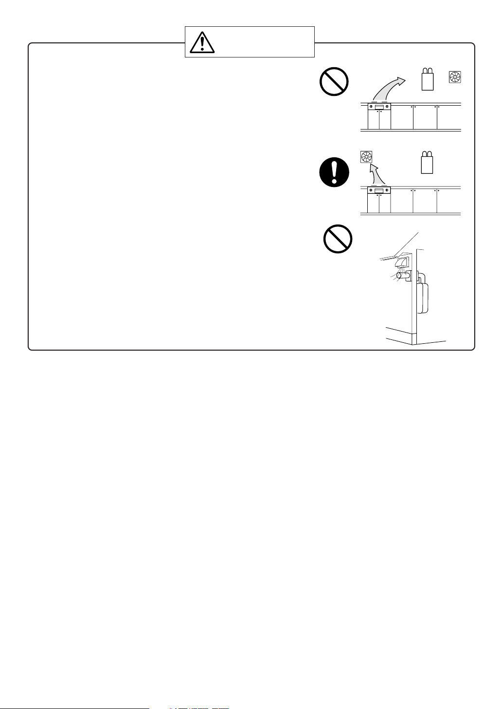
• Avoid installation above gas ranges or stoves.
• Avoid installation between the kitchen fan and stove.
If oily fumes or a large amount of steam are present in the
installation location, take measures to prevent the fumes
and steam from entering in the equipment.
• Install in a location where the exhaust gas flow will not be
affected by fans or range hoods.
• Take care that noise and exhaust gas will not affect neighbors.
Avoid installation on common walls as the unit will make
some operational noises while it is running.
• Before installing, make sure that the exhaust flue termination
will have the proper clearances according to the National Fuel
Gas Code (ANSI Z223.1).
• Installation must conform with local codes, or in the absence
of local codes, the National Fuel Gas Code, ANSI Z223.1/NFPA
54- latest edition and/or CSA B149.1, Natural Gas and Propane
Installation Code (NSCNGPIC).
Prohibited
Be sure to do
Prohibited
State of California: The boiler must be braced, anchored or strapped to avoid moving during an earthquake. Contact local utilities for code requirements in your area or call: 1-866-766-7489 and request
instructions.
For Venting Manufacturers Requirements, see websites or phone numbers listed below:
Noritz N-Vent www.noritz.com
5
5. Installation Clearances
WARNING
Before installing, check for the following:
Install in accordance with relevant building and mechanical codes, as well as any local, state or
national regulations, or in the absence of local and state codes, to the National Fuel Gas Code ANSI
Z223.1/NFPA 54 – latest edition. In Canada, see NSCNGPIC for detailed requirements.
Item
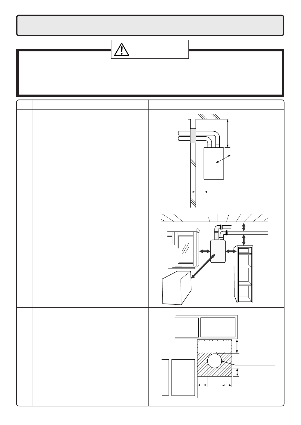
• Maintain the following clearances
from both combustible and
non-combustible materials.
Distance from combustibles
• If possible, leave 8" or more on either
side of the unit to facilitate inspection.
• If possible, leave 24" or more in front of
the unit to facilitate maintenance
and service if necessary.
• If possible, leave 3" or more above and
below the vent pipe to facilitate inspec-
repair/inspection
tion and repair if necessary
Securing of space for
Check Illustration
2" or
more
Distance from
the side
8" or
more
8" or
more
24" or
more
12"
or
more
4" or
more
3"
or more
3"
or more
• There must be a clearance of 24" or
more in front of the Flue terminal.
• This restriction will not be applied to an
area where an effective shield makes a
clearance of 24" or more in front of the
exhaust outlet.
into Any Building
Outdoor Clearances to Opening
6
There must be no
building opening
within this area.
12"
or more
12" or
more
12" or
more
Flue terminal
12" or
more
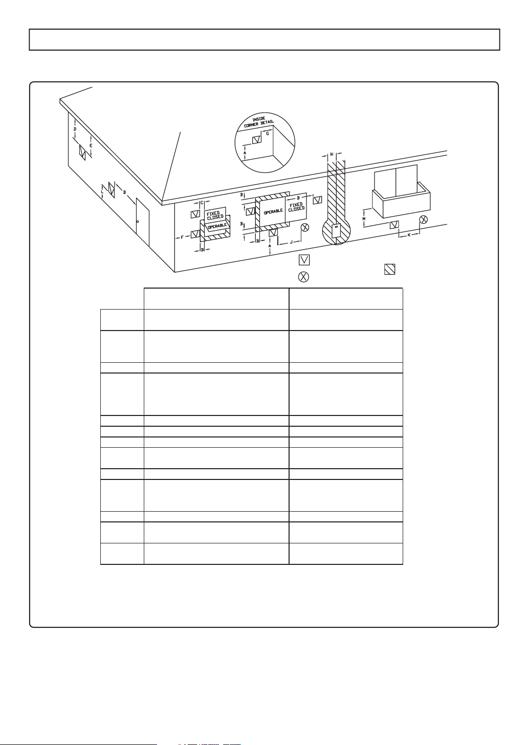
Clearance Requirements from Vent Terminations to Building Openings
* All clearance requirements are in accordance with ANSI Z21.13 and the National Fuel Gas Code,
ANSI Z223.1 and in Canada, in accordance with NSCNGPIC.
Clearance
Above grade, veranda, porch, deck,
A=
or balcony
Window or door that may be opened
B=
Permanently closed window
C=
Vertical clearance to ventilated soffit
located above the terminal within a
D=
horizontal distance of 2 feet from the
center of the terminal
Unventilated soffit
E=
Outside corner
F=
Inside corner
G=
Each side of center line extended
H=
above meter/regulator assembly
Service regulator vent outlet
I=
Nonmechanical air supply inlet or
J=
combustion air inlet to any other
appliance
Mechanical air supply inlet
K=
Above paved sidewalk or paved
L=
driveway located on public property
Under veranda, porch, deck, or
M=
balcony
Vent Terminal
Air Supply Inlet
12" (12")
12" (36")
*
*
*
*
*
3' within a height 15' above
meter/regulator assembly
3'
12" (36")
3' above if within 10' (6')
(7' ***)
* (12"- Canada Only****)
Area Where Terminal
is Not Permitted
()= indicates clearances required in Canada
*Maintain clearances in accordance with local installation codes and the requirements of the gas supplier
***A vent shall not terminate directly above a sidewalk or paved driveway that is located between two
single family dwellings and serves both dwellings.
****Permitted only if veranda,porch,deck,or balcony is fully open on a minimum of two sides beneath the floor.
7
6. Installation
Securing to the wall
• The weight of the device will be applied to the wall. If the strength of the wall is not sufficient, reinforcement must be done to prevent the transfer of vibration.
• Do not drop or apply unnecessary force to the device when installing. Internal parts may
Be sure to do
be damaged and may become highly dangerous.
• Install the boiler on a vertical wall and ensure that it is level.
Item
CAUTION
• When installing with bare hands, take caution to
not inflict injury.
• Be careful not to hit electrical wiring, gas, or water
piping while drilling holes.
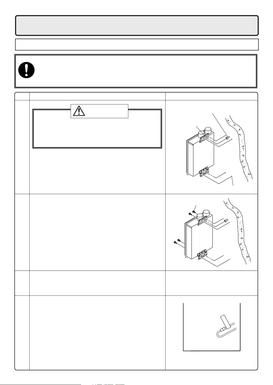
1. Drill a single screw hole, making sure to hit a stud.
2. Insert and tighten the screw and hang the boiler by
the upper wall mounting bracket.
Locating Screw Holes
3. Determine the positions for the remaining four screws
(two for the top bracket and two for the bottom), and
remove the boiler.
4. Drill holes for the remaining four screws.
5. Hang the boiler again by the first screw, and then
insert and tighten the remaining four screws.
6. Take waterproofing measures so that water does
not enter the building from screws mounting the
Mounting
device.
IllustrationCheck
Location of Screw Hole
Mounting Bracket
(upper)
Locating Screw Holes
Tapping Screw
• Make sure the boiler is installed securely so that it
will not fall or move due to vibrations or earthquakes.
Structure
• If this boiler is being installed at an elevation of 2,000
ft. (610m) or higher, disconnect the connector labeled
"High Elevation Disconnect" as illustrated on the right.
This connector is located inside the unit.
• Disconnect power to the boiler before disconnecting
this connector. Failure to perform this step will result in
a "733" code displayed on the boiler control panel and
a cease in operation. If this occurs, disconnect, then
Above 2,000 ft.
reconnect power to the boiler to reset the system.
Installations at Elevations
8
DISCONNECT
HIGH ELEVATION
Vent Pipe Installation
7.
Vent Terminal Installation
•
Follow the installation instructions included with the vent terminal. It is suggested that the appliance be vented horizontally
through a sidewall. If a vertical vent termination is required, it must follow the requirements of this section (p.9-12).
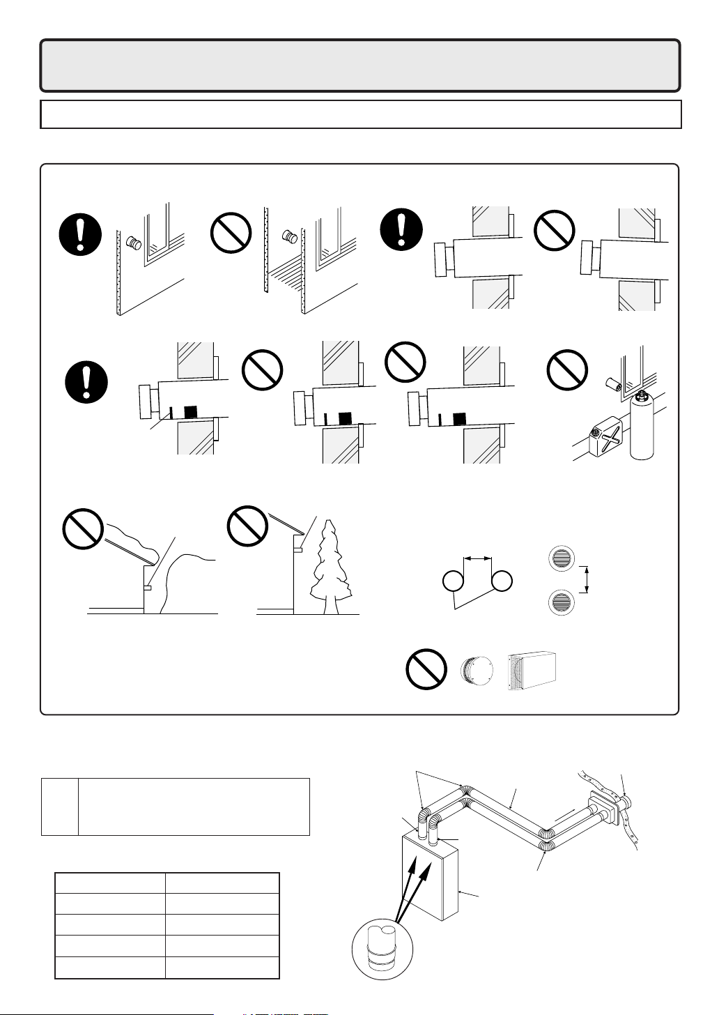
Vent Terminal Installation Precautions
• Do not install the vent terminal indoors • Install the vent terminal with a downward slope
• Install with the proper length protruding through the wall
Proper installation. The
red line can be seen,but
the red rectangle cannot
be seen from the outside.
Avoid installing the terminal where obstacles will block it
•
Vent terminal
Snow
drift
not far
enough
Note the following vent terminal installation requirements
upward
slope
Gasoline
Gas
60" or more
Vent terminal
Tree
downward
slope
too far
•
Clearance from vent terminal.
If multiple boilers are installed, terminals
must be separated by a minimum of
either 12" horizontally or 60" vertically.
•
12" or more
Avoid storing hazardous
objects near the terminal
• Do not cover the vent terminal with any type of
protective screen or enclosure. Blocked terminals
can cause abnormal combustion resulting in undesired performance from the boiler.
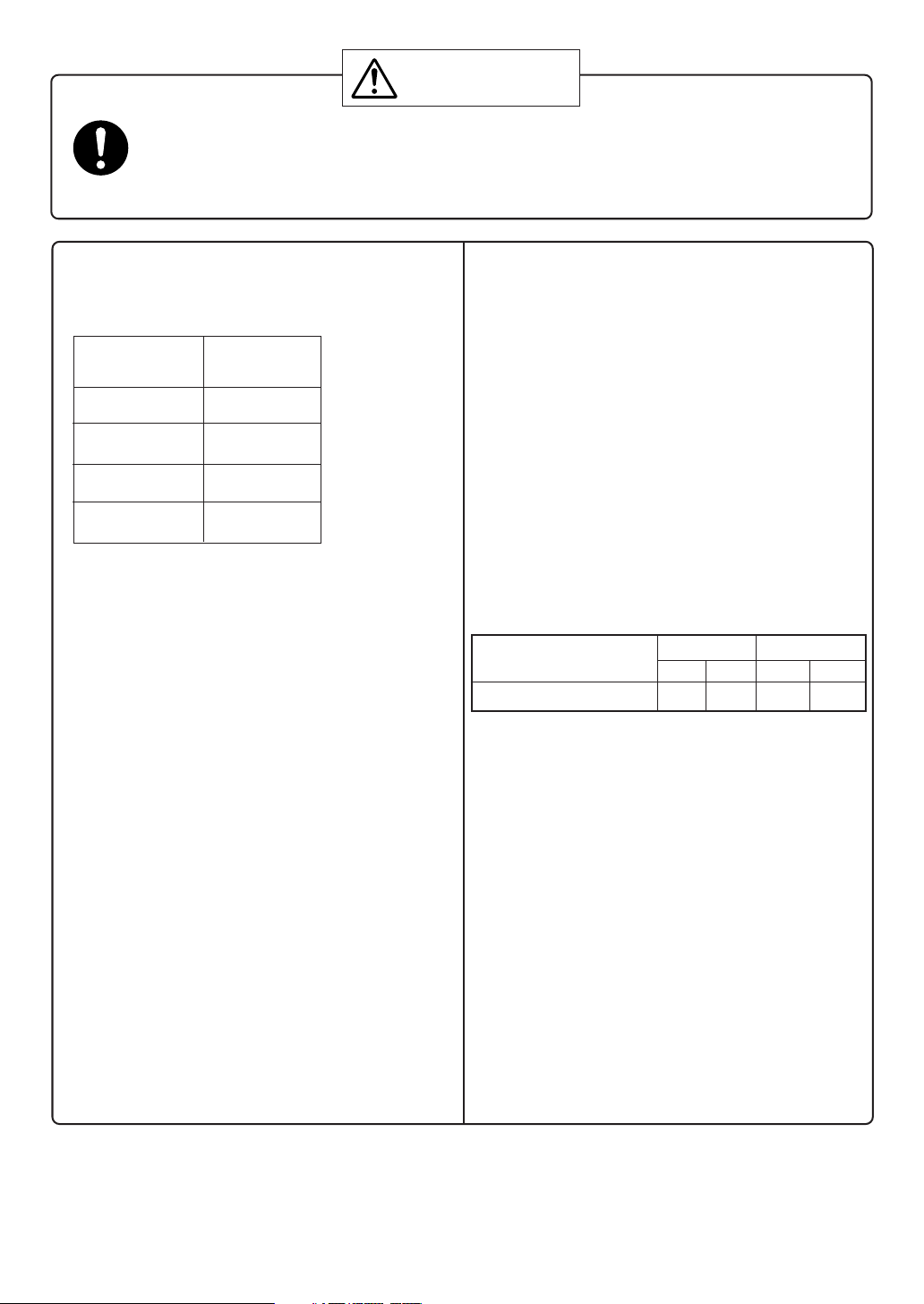
Vent terminal models
• Use only the following models of Noritz
vent terminals with this boiler.
VT4-TL
•
Vent
•
Vent terminal size variations are listed in the table below.
Choose the model according to the wall thickness required.
VT4-TS
•
terminal
Model
VT4-TL-5 3.5" to 5.1"
VT4-TL-8 5.1" to 8.3"
VT4-TL-14 8.3" to 14.6"
VT4-TL-27 14.6" to 27.2"
(for long vent runs)
(to be installed directly
on top of the appliance)
Wall thickness (in.)
Vent system installation example
Elbows
Intake pipe
Vent terminal
Straight pipe
Exhaust
pipe
Elbow
Boiler
Use a listed Category III vent adapter
to connect the flue collar to the vent
system. Use Category III vent pipe
for the entire length of the exhaust pipe.
Vent terminal
Vent terminal
sloping down
9
Be sure to do
WARNING
CARBON MONOXIDE POISONING
Follow all vent system requirements in accordance with relevant local or state regulation,
or, in the absence of local or state code, in the U.S. to the National Fuel Gas Code ANSI
Z233.1/NFPA 54 – latest edition, and in Canada, in accordance with NSCNGPIC.
Venting Precautions
• Use 4" diameter Category III vent pipe.
• Maximum vent length
Number of 90
degree elbows
4
3
2
1
* Not including the termination
• Exceeding the maximum vent length is danger-
ous and may result in bad combustion.
• If possible,don ’t install the vent pipe through any
enclosed areas. If necessary,consult the pipe
manufacturer ’s instructions for clearances.
•
Install the vent terminal so that all exhaust is di-
rected to and all intake air is taken from outdoors.
• In the Commonwealth of Massachusetts a car-
bon monoxide detector is required for all side
wall horizontally vented gas fuel equipment.
Please refer to Technical Bulletin TB 010606 for
full installation instructions.
• Do not store hazardous or flammable sub-
stances near the vent terminal and check that it
is not blocked in any way.
• Slope the intake and exhaust pipes downwards
1/4" for every 12" towards the termination.
• Use only UL listed Category III venting products.
• Connect the vent pipe firmly so that it will prevent
exhaust gases from leaking.
•
Steam or condensed water may come out from the
vent termination. Select the location for the termination so as to prevent injury or property damage.
• If this product will be installed in an area where
snow is known to accumulate, protect the vent
termination from blockage by snow drifts or damage from snow falling off of roofs.
Maximum
Vent Length*
39'
45'
51'
57'
• Support the vent pipe with hangers at intervals
as required by the vent pipe manufacturer ’s installation instructions.
• Install the vent terminal so that it is easily
accesible for maintenance both from the indoors
and the outdoors.
• If the vent terminal will be installed higher than
the boiler, make the vertical section directly
above the boiler as short as possible,and slope
down to the terminal. Do not have another vertical section after the horizontal section begins.
• Make the vertical pipe as short as possible.
• Follow the vent pipe manufacturer's installation
instructions.
• Maintain the same vent pipe diameter all the
way to the end.
• Maintain the following clearances for the
exhaust pipe to combustibles:
Manufacturer and Enclosed Unenclosed
Product Hor. Vert. Hor. Vert.
Noritz N-Vent 4" 1" 1"
Clearances vary by manufacturer, refer to the UL
approved clearances when using materials other
than N-Vent.
• Do not common vent or connect more than
one appliance to this venting system.
• Terminate at least 12"above grade or snow line
• Terminate at least 7'above a public walkway
• Use a condensation drain if necessary
Appliance Adapters
When using a vent system other than N-Vent, an
appliance adapter will be required to properly
connect the vent to this appliance. Consult the
manufacturer's instructions for the proper appliance adapter.
10" (sides)
15"(top)
6"(bottom)
10
DANGER
The boiler is not intended to be common vented with any other existing appliance!
Boiler removal from a common vent system
At the time of removal of an existing heater, the following steps shall be followed with each appliance
remaining connected to the common venting system placed in operation, while the other appliances
remaining connected to common venting system are not operating.
1. Seal any unused openings in the common venting system.
2. Visually inspect the venting system for proper size and horizontal pitch to determine if there is
blockage, leakage, corrosion or other deficiencies that could cause an unsafe condition.
3. If practical, close all building doors, windows and all doors between the space in which the appliance remains connected to the common venting system located and other spaces in the building.
Turn on clothes dryers and any appliances not connected to the common venting system. Turn on
any exhaust fans, such as range hoods and bathroom exhausts, at maximum speed. Do not
operate a summer exhaust fan. Close all fireplace dampers.
4. Place in operation the appliance being inspected. Follow the lighting instructions. Adjust the
thermostat so the appliance will operate continuously.
5. Test for spillage at the draft hood relief opening after 5 minutes of main burner operation. Use the
flame of a match or candle or smoke from a cigarette.
6. After it has been determined that each appliance remaining connected to common venting system
properly vents when tested as outlined, return doors, windows, exhaust fans, fireplace dampers
and any other gas burning appliance to their previous condition of use.
7. Any improper operation of the common venting system should be corrected so the installation
conforms with the National Fuel Gas Code, ANSI Z223.1/NFPA 54 and/or CAN/CSA B149.1,
Natural Gas and Propane Installation Code. When resizing any portion of the common venting
system, the common venting system should be resized to approach the minimum size as determined using the appropriate tables in Part 11 of the National Fuel Gas Code ANSI Z223.1/NFPA
54 and/or CAN/CSA B149.1 Natural Gas and Propane Installation Code.
11
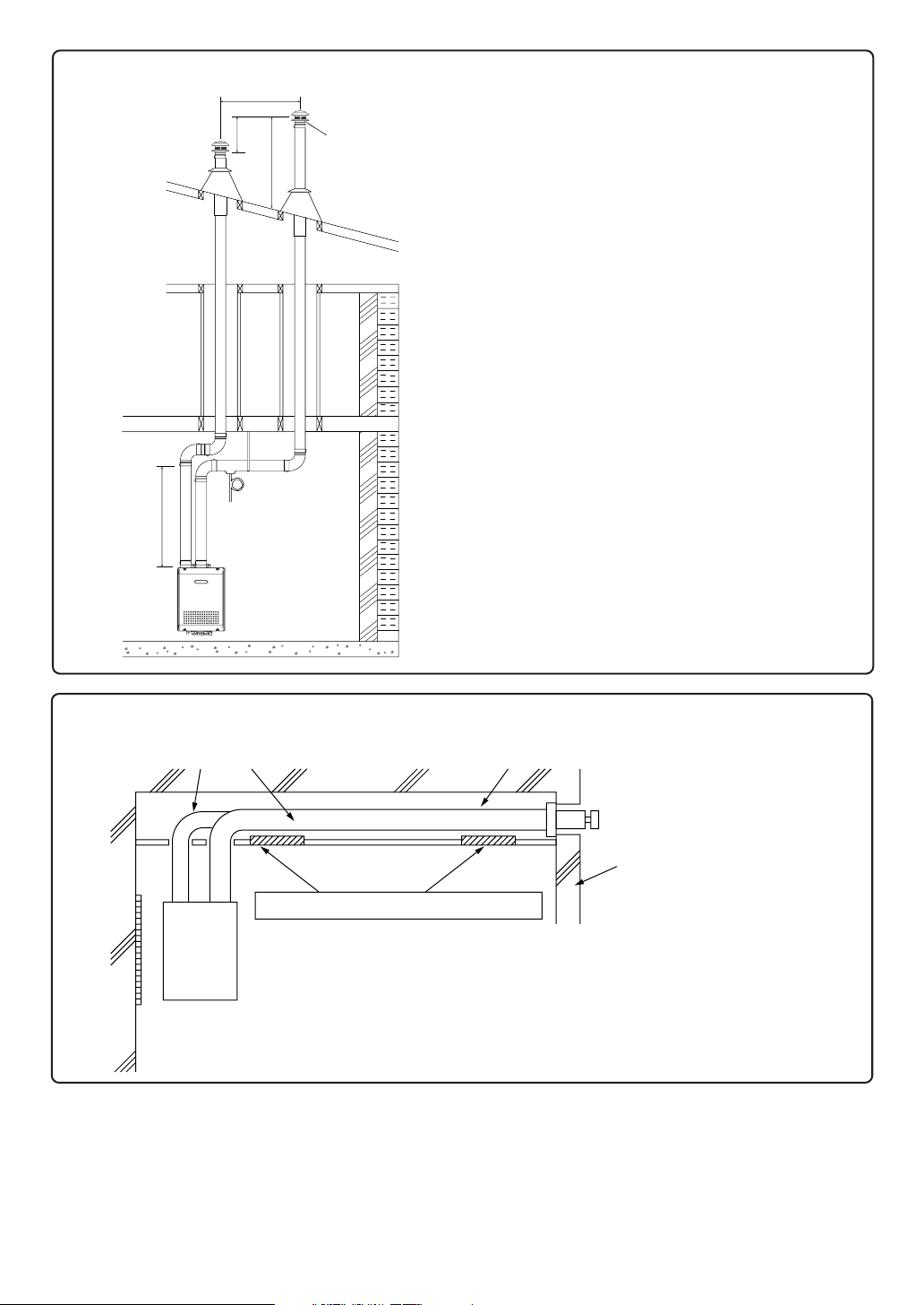
Vertical Vent Termination
6'
1-2'
Intake Air
Elbow
**1' Min. - 3' Max.
2'
Min.
Roof
Jack
Hanger
Strap
Condensation
Drain (Install
According to
Local Codes)
Appliance
Adapter*
* Adapter not required when
using Noritz N-Vent.
**1' minimum recommended,
but not required. Avoid installing
elbow directly on flue.
Exhaust
RainCap
Storm
Collar
Flashing
Firestop/
Support
Firestop
Roof
• Terminate at least 6' from the combustion air
intake of any appliance, and 3' from any
other building opening, gas utility meter, service
regulator etc.
• Enclose exterior vent systems below the roof
line to limit condensation and protect against
mechanical failure.
• When the vent penetrates a floor or ceiling and
is not running in a fire rated shaft, a firestop and
support is required.
• When the vent termination is located not less
than 8' from a vertical wall or similar obstruction,
terminate above the roof at least 2', but not
more than 6', in accordance with the National
Fuel Gas Code ANSI Z223.1/NFPA 54.
• Provide vertical support every 12' or as required
by the vent pipe manufacturer's instructions.
•A short horizontal section is recommended to
prevent debris from falling into the water heater.
• Install a condensation drain in the horizontal
section of the venting.
• Slope the horizontal section 1/4" for every 12"
toward the drain tee.
When the intake/exhaust pipes pass through an enclosed space:
Intake pipe
(Combustible material)
Ceiling
Suggested inspection openings (18" x 18")
• Inspection openings are suggested for the vent intake and exhaust
pipes if they are installed in an enclosure. These openings should
be near the entrance and exit of the vent into the enclosure.
• These openings should be 18" x 18".
Sloping down toward vent terminalExhaust pipe
External wall,
combustible material
12
Gas Piping
8.
Follow the instructions from the gas supplier.
The appliance and its individual shutoff valve must be disconnected from the gas supply piping system
during any pressure testing of that system at test pressures in excess of 1⁄2 psi (3.5 kPa).
The Appliance must be isolated from the gas supply piping system by closing its individual manual shutoff valve
during any pressure testing of the gas supply piping system at test pressures equal to or less than
1
⁄2 psi (3.5 kPa).
The appliance and its gas connections must be leak tested before placing the appliance in operation.
The inlet gas pressure must be within the range specified. This is for the purposes of input adjustment.
In order to choose the proper size for the gas line, Installation must conform with local codes, or in the
absence of local codes, the National Fuel Gas Code, ANSI Z223.1/NFPA 54- latest edition and/or CSA
B149.1, Natural Gas and Propane Installation Code (NSCNGPIC).
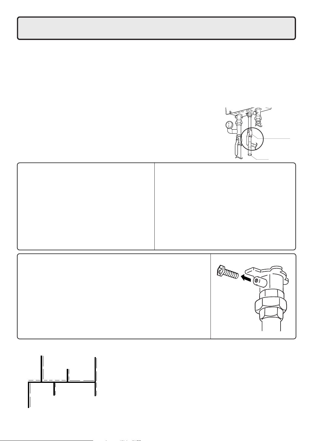
A sediment trap must be installed upstream of the gas controls.
The sediment trap can be installed as illustrated to the right or as
allowed by applicable codes.
Gas supply valve
Drip leg
Gas Pressure
Size the gas line according to total btuh demand
of the building and length from the meter or
regulator so that the following supply pressures
are available even at maximum demand:
Natural Gas Supply Pressure
Min. 4" WC
Max. 10.5" WC
LP Gas Supply Pressure
Min. 8" WC
Max. 14" WC
Gas Meter
Select a gas meter capable of supplying the entire
btuh demand of all gas appliances in the building.
Gas Connection
• Do not use piping with a diameter smaller than
the inlet diameter of the boiler.
• Flexible gas pipes not conforming to NH199-DV
(199,900 Btuh) or NH150-DV (150,000 Btuh)
standards are not recommended.
• Install a gas shutoff valve on the supply line.
• Use only approved gas piping materials.
Measuring Gas Pressure
[Primary gas pressure]
In order to check the gas supply pressure to the unit, a tap is provided on the gas inlet. Remove the hex head philips screw from the
tap, and connect a manometer using a silicon tube. (Right figure)
[Manifold pressure]
In order to check the gas manifold pressure, tap is are provided on
the gas valve inside the unit. The pressure can be checked either by
removing the hex head philips screw and connecting a manometer
with a silicon tube, or by removing the 1/8" NPT screw with an allen
wrench and connecting the appropriate pressure gauge.
Sample Gas Line
Noritz NH199-DV (199,900 Btuh)
Noritz NH150-DV (150,000 Btuh)
Outlet E
10'
Section 4
Natural Gas
Meter
Section 3 Section 2
5' 5'
5'
Outlet D
10'
Gas Fireplace
(25,000 Btuh)
**See next page for the pipe capacity charts.
Outlet C
5'
Clothes Dryer
(35,000 Btuh)
5'
Outlet A
Section 1
10'
Barbecue
(50,000 Btuh)
10'
5'
Outlet B
Gas Range Stove
(65,000 Btuh)
1. Size each outlet branch starting from the furthest
using the Btuh required and the length from the
meter.
2. Size each section of the main line using the
length to the furthest outlet and the Btuh
required by everything after that section.
Outlet A: 45' (Use 50'), 50,000 Btuh requires 1/2"
Outlet B: 40', 65,000 Btuh requires 1/2"
Section 1: 45' (Use 50'), 115,000 Btuh requires 3/4"
Outlet C: 30', 35,000 Btuh requires 1/2"
Section 2: 45' (Use 50'), 150,000 Btuh requires 3/4"
Outlet D: 25' (Use 30'), 25,000 Btuh requires 1/2"
Section 3: 45' (Use 50'), 175,000 Btuh requires 1"
Outlet E: 25' (Use 30'), NH199-DV (199,900 Btuh) requires 3/4",
Section 4: 45' (Use 50'), NH199-DV (374,900 Btuh) requires 1-1/4",
Instructions
Sample Calculation
NH150-DV (150,000 Btuh) requires 3/4",
NH150-DV (325,000 Btuh) requires 1-1/4".
13
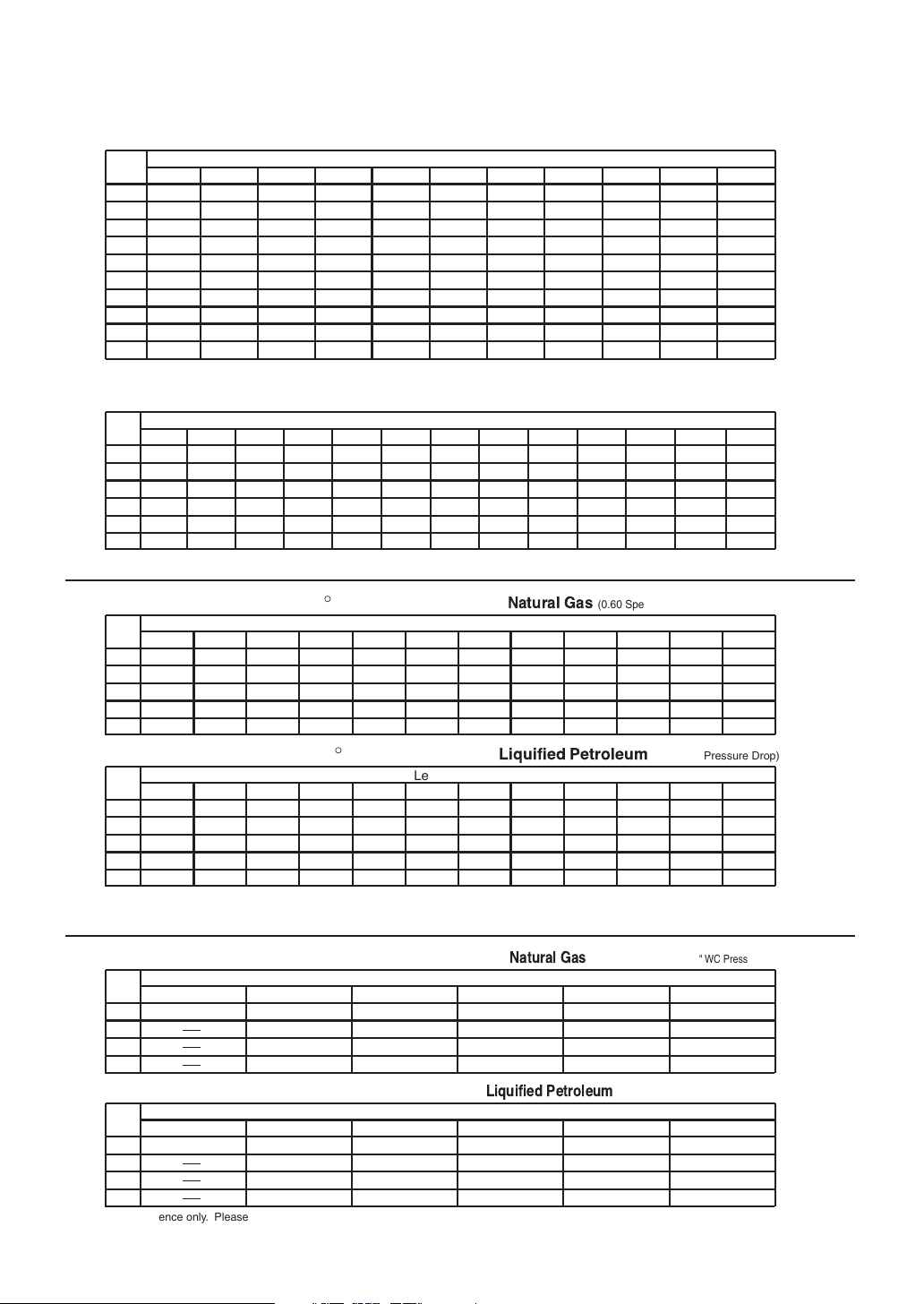
Maximum Natur
Natur
Liquified P
Pipe
10' 20' 30' 40' 50' 60' 70' 80' 90' 100' 125'
Size
1/2"
174
3/4"
363
1"
684
1404
1 1/4"
2103
1 1/2"
4050
2"
2 1/2"
6455
3"
11,412
16,709
3 1/2"
4"
23,277
Contact the Gas Supplier for Btu/Cubic Ft. of the Supplied Gas. 1000 BTU/Cubic Ft. is a Typical Value
Gas Line Sizing Charts
Adapted from UPC 1997
al Gas Delivery Capacity in Cubic Feet per Hour (0.60 Specific Gravity, 0.5" WC Pressure Drop)
Length in Feet
119
249
470
965
1445
2784
4437
7843
11,484
15,998
96
200
377
775
1161
2235
3563
6299
9222
12,847
82
171
323
663
993
1913
3049
5391
7893
10,995
73
152
286
588
880
1696
2703
4778
6995
9745
66
138
259
532
798
1536
2449
4329
6338
8830
61
127
239
490
734
1413
2253
3983
5831
8123
56 53 50 44
118 111 104 93
222 208 197 174
456
683
1315
2096
3705
5425
7557
428
641
1234
1966
3476
5090
7091
404
605
1165
1857
3284
4808
6698
1033
1646
2910
4261
5936
358
536
Maximum Liquified P
Pipe
10' 20' 30' 40' 50' 60' 70' 80' 90' 100' 125' 150' 200'
Size
1/2"
275
3/4"
567
1071
1"
2205
1 1/4"
3307
1 1/2"
2"
6221
** For reference only. Please consult gas pipe manufacturer for actual pipe capacities.
Maximum Capacity of Flex TracPipe in Cubic Feet per Hour of
Pipe
Size
10' 20' 30' 40' 50' 60' 70' 80' 90' 100' 150' 200'
206
3/4"
1"
383
614
1 1/4"
1 1/2"
1261
2"
2934
Maximum Capacity of Flex TracPipe in Thousands of Btuh
Pipe
Size
10' 20' 30' 40' 50' 60' 70' 80' 90' 100' 150' 200'
325
3/4"
1"
605
971
1 1/4"
1 1/2"
1993
2"
4638
** For reference only. Please consult gas pipe manufacturer for actual pipe capacities.
Tr acPipe® is a registered trademark of Omega Flex.
etroleum (Undiluted) Delivery Capacity in Thousands of Btuh (0.5" WC Pressure Drop)
Length in Feet
189
152
129
114
103
96
393
732
1496
2299
4331
147
269
418
888
2078
232
425
661
1404
3285
315
590
1212
1858
3465
1143
2684
121
218
334
723
1698
191
344
528
267
504
1039
1559
2992
105
188
284
625
1472
166
297
449
988
2327
R
1417
2646
R
237
448
913
94
168
251
559
1317
149
265
397
884
2082
217
409
834
1275
2394
Length in Feet
86
153
227
509
1203
Length in Feet
136
241
359
805
1902
1181
2205
196
378
771
89
185
346
724
1086
2047
80
141
209
471
1114
126
222
330
745
1761
83
78
173
162
322
307
677
630
1023
976
1921
1811
75
132
194
440
1042
(0.60 Specific Gravity, 0.5" WC Pressure Drop)
71
125
181
415
983
67
118
171
393
933
118
208
307
696
1647
112
197
286
656
1554
106
186
270
621
1475
63
69
132
146
275
252
567
511
866
787
1496
1606
55
94
137
320
762
( 0.5" WC Pressure Drop)
87
143
217
506
1205
1045
55
112
213
440
675
1260
48
82
116
277
661
76
129
183
438
14
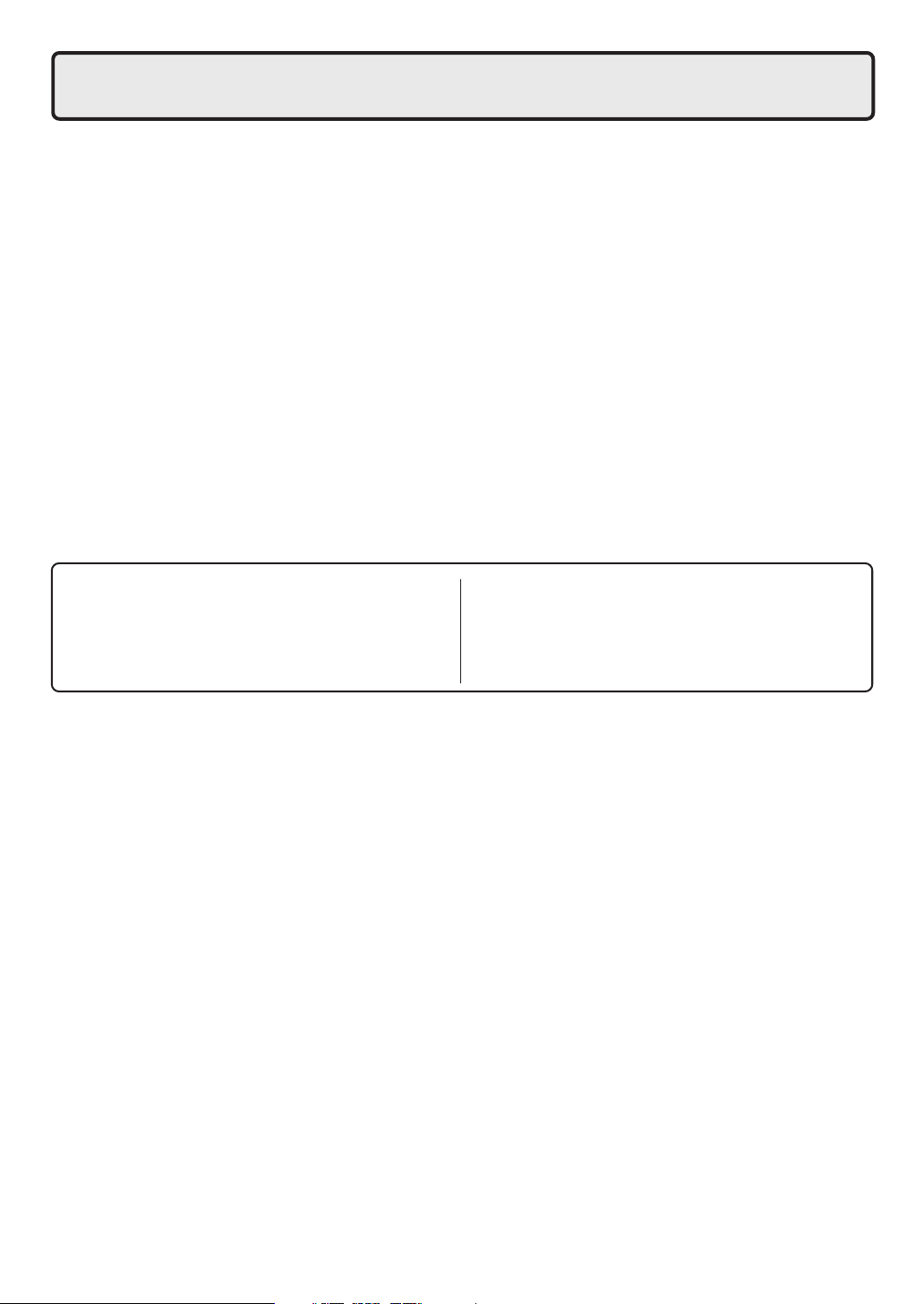
Maximum Capacity for Gas Flex Connectors in Cubic Feet per Hour of
Pipe
Size
1/2"
3/4"
1"
1 1/4"
12" 24" 36" 48" 60" 72"
180 150
290
581
1470
Length in Inches
125
255
512
1200
Maximum Capacity for Gas Flex Connectors in Thousands of Btuh
Pipe
Size
1/2"
3/4"
1"
1 1/4"
** For reference only. Please consult gas pipe manufacturer for actual pipe capacities.
12" 24" 36" 48" 60" 72"
288 240
465
930
2352
Length in Inches
200
409
825
1920
106
215
442
1130
169
344
708
1808
(0.60 Specific Gravity, 0.5" WC Pressure Drop)
93
197
397
960
( 0.5" WC Pressure Drop)
149
315
638
1536
86
173
347
930
137
278
556
1488
Installation and service must be performed by a qualified plumber. In the
Commonwealth of Massachusetts, this product must be installed by a licensed
9.
This appliance is suitable for space heating applications. Do not use this appliance if any part has been underwater.
Immediately call a qualified service technician to inspect the appliance and replace any part of the control system and
gas control which has been under water.
A relief valve that is rated in accordance with and complying with The ANSI/ASME Boiler and Pressure Vessel Code,
Section IV ( Heating Boilers ) must be installed on the left side of the case. A pressure relief valve, fitting, and gasket
is provided with this boiler and should be installed as shown below. This pressure relief valve must have the hourly
rated temperature discharge capacity (199,900 Btuh for the NH199-DV, 150,000 Btuh for the NH150-DV). The relief
capacity must not exceed 30 psi. No valve shall be placed between the relief valve and the boiler. The relief valve
must be installed such that the discharge will be conducted to a suitable place for disposal when relief occurs. No
reducing coupling or other restriction may be installed in the discharge line. The discharge line must be installed to
allow complete drainage of both the valve and the line. If this unit is installed with a separate storage vessel, the
separate vessel must have its own temperature and pressure relief valve. This valve must also comply with The
Standard for Relief Valves and Automatic Gas Shutoff Devices for Hot Water Supply Systems, ANSI Z21.22. (in the
U.S. only). A temperature relief valve is not required, but if one is used, do not install the valve with the probe directly
in the flow of water. This may cause unwarranted discharge of the valve.
Toxic chemicals, such as those used for boiler treatment, shall not be introduced into the potable water.
• Flush water through the pipe to clean out metal powder, sand and dirt before connecting it.
• Take appropriate heat insulation measures (e.g., wrapping with heat insulation materials, using electric heaters)
according to the climate of the region to prevent the pipe from freezing.
•
Use a union coupling or flexible pipe for connecting the pipes to reduce the force applied to the piping.
• Avoid using joints as much as possible to keep the piping simple.
• Avoid piping in which an air holdup can occur.
• Be sure to used approved piping materials.
Water Piping
plumber or gas fitter in accordance with the Massachusetts Plumbing and Fuel
Gas Code 248 CMR Sections 2.00 and 5.00. Observe all applicable codes.
Water piping
• When using plastic pipe, use pipe with an oxygen diffusion barrier which is manufactured to
DIN4726.
• The longer the piping, the greater the heat loss.
Try to make the piping as short as possible.
The boiler ,when used in connection with a refrigeration system, must be installed so the chilled medium is piped in
parallel with the boiler with appropriate valves to prevent the the chilled medium from entering the boiler.
The boiler piping system of a hot water boiler connected to heating coils located in air handling units where they may
be exposed to refrigerated air circulation must be equipped with flow control valves or other automatic means to
prevent gravity circulation of the boiler water during the cooling cycle.
System Sizing
• For optimal operation, design the piping and
size the pump to flow a minimum of 4.0 GPM.
15
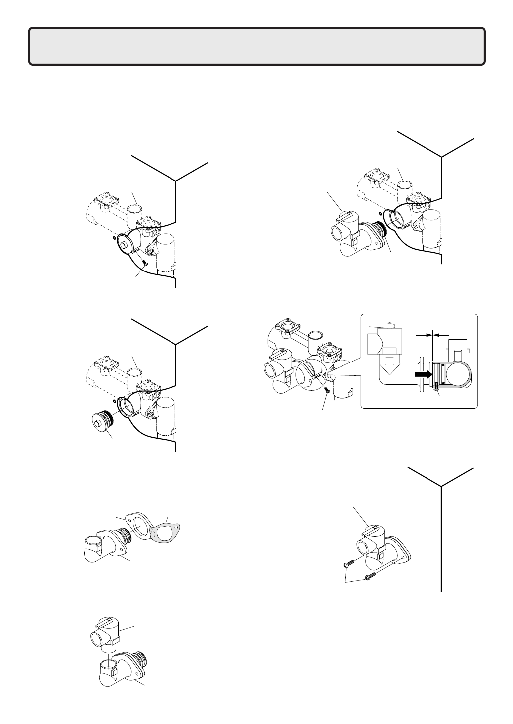
10. Relief Valve Mounting
Before installing the relief valve, test the piping at 45 psi with the cap on.
1. Remove the front cover of the unit.
2. Remove the single screw holding the cap to the
housing.
• Do not lose this screw, it will be used in a
later step.
BoilerCase
Housing
Screw
3. Remove the cap.
BoilerCase
Housing
6. Insert the relief valve assembly into the housing being
careful not to damage the o-ring. Insert and tighten
the screw that was previously removed in step 2.
BoilerCase
Housing
ReliefValveAssembly
O-ring
Press the fitting firmly into the housing while tightening
the screw. Failure to do so could cause a leak.
Cap
4. Locate the gasket supplied with the boiler, remove
the paper backing, and attach it to the supplied fitting
around the flange.
Gasket
5. Install the relief valve (supplied separately) in the fitting
before attaching it to the boiler.
PaperBacking
Fitting
SafetyReliefValve
Fitting
Screw
Screw
7. Secure the relief valve assembly to the boiler case
with the 2 supplied screws.
BoilerCase
ReliefValveAssembly
Screw
8. Replace the front cover of the unit.
NOTE
When attaching the drain line to the end of the relief
valve, do not apply excess force to the end of the relief
valve assembly. Excessive force can damage both the
casing and the internal piping.
16

11. Plumbing Applications
The boiler piping system of a hot water boiler connected to heating coils located in air handling units where they may
be exposed to refrigerated air circulation must be equipped with flow control valves or other automatic means to
prevent gravity circulation of the boiler water during the cooling cycle.
- Before operating for the first time, confirm that 2.5 GPM flows through with only the bypass circuit opened (with the
heating and indirect domestic hot water loops closed).
* This flow rate can be confirmed by adjusting the gate valve on the bypass circuit until the controller indicates that the
unit is heating.
- Do not install air separators where negative pressure can develop in the system. Air will be drawn in. Install air
separators at the highest level in the system
- Inspect expansion tanks once a year to confirm there is enough air in them.
- Test the pressure relief valve once a year to ensure is works properly.
- This unit is designed so that the indirect water heating loop will have priority over the hydronic heating loop, so
design the system so that the air handler will shut down if it is not receiving hot water.
- This product is designed with a water flow switch, so no LWCO is necessary. If local codes require a LWCO, install
it on the power supply line. Refer to the installation and instruction manual of the LWCO for details.
- There is a filter on the return into the unit. Clean this after installation and again during inspection.
- This product was shipped with a cap where the relief valve should be installed. After installation, test the piping at 45
psi with the cap on, and then install the relief valve afterwards.
Pump Cautions
- Use the circulating pumps listed below or their equivalents. Add a pump if these are too small. The pump terminal
in the unit is rated for 2.2 Amps. (See p.25 for instructions for pumps that require greater than 2.2 Amps).
Taco Model 0013:F3 (1/6 HP) Grundfos Model 26-99F (1/6 HP)
Size the circulating pump based on the pressure loss of the boiler and the piping.
- Install the circulating pump near the return to the boiler.
Electrical Cautions
- Connect the power to the circulating pumps to the terminal in the boiler.
- This model does not require a boiler protection loop.
- The unit may operate under cold weather conditions to prevent freezing.
- The freeze protection in this appliance relies on the ability to control the water that is circulating through it. In order to
be protected from cold weather, please make sure that nothing will prevent the unit from being able to circulate water:
- The freeze prevention in this appliance will not work if power is lost or disconnected, if power is not connected to
the pump, if the pump is not connected to the unit, or if the pump fails.
- Additionally, if any of the loops that the boiler is supplying hot water to is blocked or shut off, the freeze
prevention may not be able to function properly.
- Connect the pump on the indirect water heating loop to the discharge side of the pump for the heating loop (See
diagram)
- Use an aquastat on the indirect domestic water heating tank and connect it to the Priority 1 terminal inside the boiler.
Connect the thermostat of the heating system to the Priority 2 terminal in the boiler.
-A 15 VDC, 0.1 Amp signal flows in the terminals. Use low Amp thermostats or zone controllers. 15 Amp devices may
not operate properly.
Anti-freeze Requirements
- Use only inhibited propylene glycol solutions which are specifically formulated for hydronic systems. When using
anti-freeze, use Noritz approved anti-freeze only. Do not use ethylene glycol or any other substitutes.
- The anti-freeze must be used and maintained according to the anti-freeze manufacturer's instructions.
Damages caused by misuse of anti-freeze are not covered by the Limited Warranty.
- Check the anti-freeze at least once per year for proper product concentration and pH level.
- Replace the anti-freeze every two years or as required by the anti-freeze manufacturer to prevent corrosion and
clogging of the pipes.
17
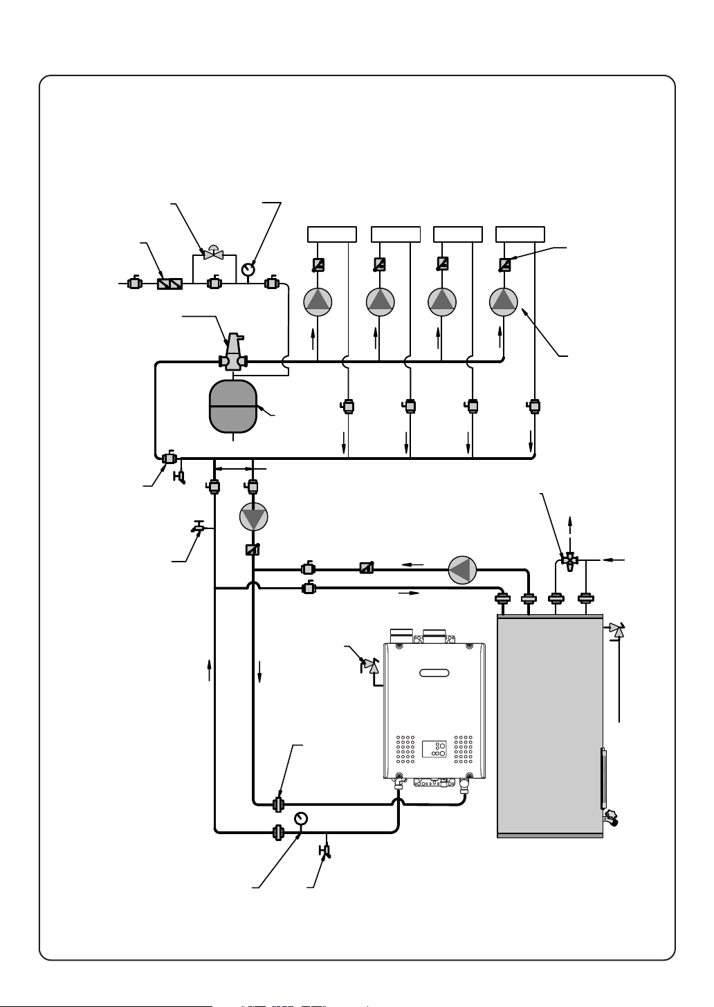
Zoned with Pumps
This drawing is meant to show system piping concept only.
Installer is responsible for all equipment & detailing required by local codes.
Refer to pages 22-25 for electrical wiring instructions.
PRESSURE
REDUCING VALVE
BACKFLOW
PREVENTER
MAKE UP WATER
AIR SEPARATOR
BALL VALVE
(TYPICAL)
DRAIN POINT
(TYPICAL)
PRESSURE
GAUGE
ZONE 1
EXPANSION
TANK
NOT TO EXCEED 12" APART
PRIORITY 2
PUMP
MIXING VALVE
PRIORITY 1
PUMP
ZONE 4ZONE 3ZONE 2
ANTI-SCALD
FLOW CHECK
VALV E
(TYPICAL)
ZONE PUMPS
(TYPICAL)
HOT
WATER
OUT
COLD
WATER
IN
18
TEMPERATURE /
PRESSURE
GAUGE
(ACCESSORIES)
SAFETY
RELIEF VALVE
(ACCESSORIES)
UNION
(TYPICAL)
DRAIN
BOILER
INDIRECT
DHW TANK
 Loading...