

Nordyne M4RC Upflow, M4RL Downflow, M4RC, M4RL, M4RC054D-24B Installation Instructions Manual
...
GAS FURNACES
Installation Instructions
Single Stage Condensing Gas Furnaces
92.1% AFUE
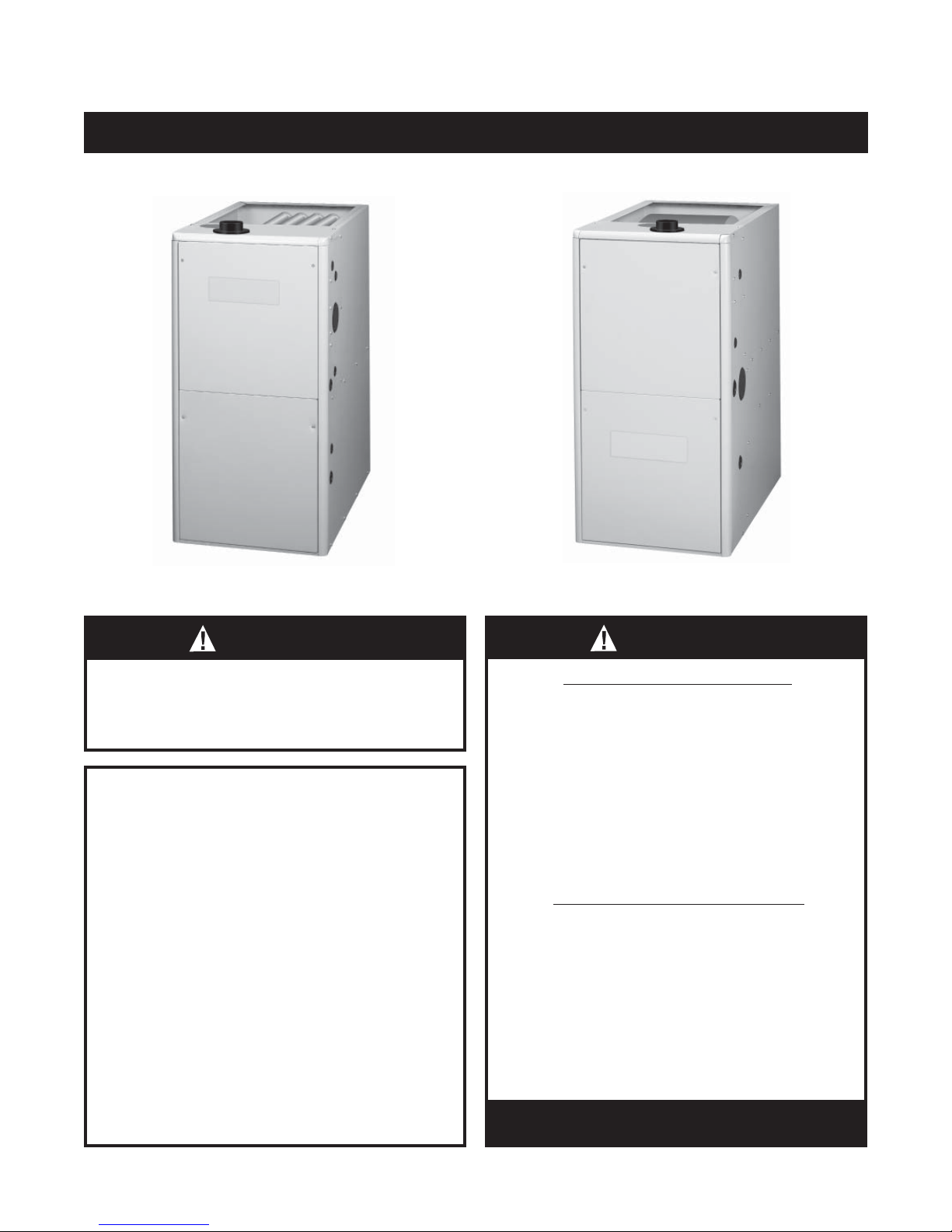
M4RC Upfl ow Furnace
WARNING:
PROPOSITION 65 WARNING: This product
contains chemicals known to the state of
California to cause cancer, birth defects or
other reproductive harm.
ATTENTION INSTALLERS:
It is your responsibility to know this product better than your
customer. This includes being able to install the product
according to strict safety guidelines and instructing the
customer on how to operate and maintain the equipment for
the life of the product. Safety should always be the deciding
factor when installing this product and using common sense
plays an important role as well. Pay attention to all safety
warnings and any other special notes highlighted in the
manual. Improper installation of the furnace or failure to
follow safety warnings could result in serious injury, death,
or property damage.
These instructions are primarily intended to assist qualifi ed
individuals experienced in the proper installation of this
appliance. Some local codes require licensed installation/
service personnel for this type of equipment. Please read all
instructions carefully before starting the installation. Return
these instructions to the customer’s package for future
reference
.
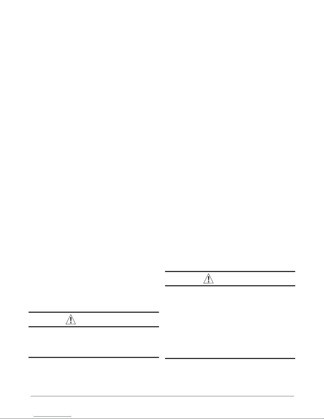
M4RL Downfl ow Furnace
WARNING:
FIRE OR EXPLOSION HAZARD
• Failure to follow safety warnings exactly
could result in serious injury or property
damage.
• Installation and service must be performed
by a qualifi ed installer, service agency or
the gas supplier.
• Do not store or use gasoline or other
fl ammable vapors and liquids in the
vicinity of this or any other appliance.
WHAT TO DO IF YOU SMELL GAS
• Do not try to light any appliance.
• Do not touch any electrical switch; do not
use any phone in your building.
• Leave the building immediately.
• Immediately call your gas supplier from a
neighbors phone. Follow the gas suppliers
instructions.
• If you cannot reach your gas supplier, call
the fi re department.
DO NOT DESTROY.
KEEP IN A SAFE PLACE FOR FUTURE REFERENCE.

TABLE OF CONTENTS
SAFETY INFORMATION .............................................3
REQUIREMENTS AND CODES ..................................4
GENERAL INSTRUCTIONS ........................................5
Manufacturer Warranty ............................................5
Combustion Air Quality ............................................5
Installation in a Garage ............................................ 5
Heating Load ...........................................................6
Clearances to Combustible Materials ......................6
COMBUSTION AIR REQUIREMENTS ........................6
General Information ................................................. 6
Installation in Confi ned Spaces ............................... 7
Air From Inside .................................................... 7
Outdoor Air from a Crawl Space or
Vented Attic .........................................................7
Outdoor Air Using Vertical Ducts ........................ 7
Outdoor Air Using Horizontal Ducts .................... 7
Air Directly Through an Exterior Wall .................8
Alternate Method of Providing air from
Outside ............................................................... 8
Installation in Unconfi ned Spaces ........................... 8
VENTING REQUIREMENTS ......................................10
Vent Pipe Length and Diameter ............................. 10
Vent Pipe Material ................................................. 11
Vent Pipe Installation ............................................. 11
Outdoor Terminations - Horizontal Venting ............ 11
Outdoor Terminations - Vertical Venting ................. 12
Vent Freezing Protection ....................................... 12
Condensate Disposal ............................................ 13
Concentric Vent Termination .................................. 13
Existing Installations .............................................. 13
CIRCULATING AIR REQUIREMENTS ...................... 14
Plenums and Air Ducts .......................................... 14
Return Air Connections .........................................14
Supply Air Connections ......................................... 15
Acoustical Treatments............................................ 15
FURNACE INSTALLATION ....................................... 15
General Requirements .......................................... 15
Requirements and Codes .....................................15
Upfl ow Furnace Installation .................................. 16
Downfl ow Furnace Installation .............................. 16
Alternate Attachment Method ........................... 18
Bottom Panel Removal .......................................... 19
Alternate Bottom Panel Removal ...................... 19
Pressure Switch Relocation .................................. 19
Inducer Assembly Rotation ...................................20
2
Direct Vent (2 - Pipe) Applications ......................... 20
Vent and Inducer Assembly Options ..................... 20
Accessories ..........................................................21
Finish Flange ....................................................21
Rubber Grommets ............................................21
Inline Drain Assembly .......................................21
PVC TEE, Reducer, and Hose Barbs ...............21
Condensate Drain Lines ...................................22
Filter Retainer Brackets ....................................22
Ventilaire™ Bracket...........................................22
Vent Couplings ..................................................23
Upfl ow Furnaces ...........................................23
Downfl ow Furnaces .......................................23
Alternate Vent Pipe Installation .............................23
GAS SUPPLY AND PIPING .......................................24
Leak Check ..........................................................24
High-Altitude Application .......................................24
Conversion to LP/Propane ....................................25
ELECTRICAL WIRING ...............................................29
Low Voltage Wiring ................................................29
Line Voltage Wiring................................................29
Grounding .............................................................29
Twinning ................................................................30
START-UP & ADJUSTMENTS ...................................31
Pre-Start Checklist ................................................31
Start-Up Procedures .............................................31
Verifying and Adjusting Input Rate ........................31
Verifying and Adjusting Temperature Rise ............31
Verifying Burner Operation ....................................31
Verifying Operation of the supply Air
Limit Switch ...........................................................32
OPERATING SEQUENCE .........................................32
Heating Cycle ........................................................32
Cooling Cycle ........................................................32
Fan Mode ..............................................................32
MAINTENANCE .........................................................32
Air Filters ...............................................................33
Blower Compartment ............................................33
Cleaning of Burners ..............................................33
Heat Exchanger and Burner Maintenance ............33
Lubrication ............................................................33
Vent System ..........................................................33
DESCRIPTION OF COMPONENTS ..........................34
TROUBLESHOOTING ...............................................34

FRENCH TRANSLATIONS ........................................35
FIGURES AND TABLES ............................................37
Figure 40 - Furnace Dimensions .......................37
Table 8 - Blower Performance Chart
Electrical Information ..............................................39
Figure 41 - Wiring Diagram ................................39
Gas Information ......................................................40
Table 9 Table 10 Table 11 - High Altitude Deration Chart for
Table 12 - Natural
Table 13 - High Altitude Deration Chart for
Table 14 - High Altitude Deration Chart for
Venting Information .................................................43
Table 15 -
Figure 42 - Horizontal and Vertical Venting ........44
Figure 43 - Upfl ow Options .................................45
Figure 44 - Downfl ow Options ............................46
Location of Furnace Components ..........................47
Figure 45 - Upfl ow/Horizontal Gas Furnace
Components.....................................47
Figure 46 -
Components ....................................47
INSTALLATION/PERFORMANCE CHECKLIST ........48
Gas Flow Rates ...................................40
Gas Pipe Capacities ..........................40
Propane Gas .....................................41
Gas Heating Values ..............41
Nat. Gas - High Heating Values .........42
Nat. Gas - Low Heating Values ..........42
Vent Termination Clearances .............43
Downfl ow Gas Furnace
..................38
SAFETY INFORMATION
Safety markings are used frequently throughout this
manual to designate a degree or level of seriousness and
should not be ignored. WARNING indicates a potentially
hazardous situation that if not avoided, could result in
personal injury or death. CAUTION indicates a potentially
hazardous situation that if not avoided, may result in minor
or moderate injury or property damage.
WARNING:
The safety information listed below must be
followed during the installation, service, and
operation of this furnace. Failure to follow safety
recommendations could result in possible
damage to the equipment, serious per
injury or death
• Use only with type of gas approved for this furnace.
Refer to the furnace rating plate.
• Install this furnace in accordance to the minimum
clearances to combustible materials listed in Table 1
(page 9).
• Provide adequate combustion and ventilation air to the
furnace space as specifi ed on pages 6 - 9.
• Provide adequate clearances around the vent air intake
terminal as specifi ed in Figures 6 - 9 (pages 12 - 13).
• Combustion products must be discharged outdoors.
Connect this furnace to an approved vent system only,
as specifi ed on Pages 10 - 13.
• Never test for gas leaks with an open fl ame. Use a
commercially available soap solution to check all
connections (page 24).
• This furnace is designed to operate with a maximum
external pressure rise of 0.5 inches of water column.
Consult Table 8 (page 38), and the rating plate for the
proper circulating air fl ow and temperature rise.
NOTE: It is important that the duct system be designed
to handle the desired fl ow rate and external pressure
rise. An improperly designed duct system can result
in nuisance shutdowns, and comfort or noise issues.
• When supply ducts carry air circulated by the furnace
to areas outside the space containing the furnace, the
return air shall also be handled by duct(s) sealed to
the furnace casing and terminating outside the space
containing the furnace. See page 14.
• This furnace may not be used for temporary heating
of buildings or structures under construction.
.
sonal
3

REQUIREMENTS and CODES
This furnace must be installed in accordance with
these instructions, all applicable local building codes
and the current revision of the National Fuel Gas Code
(NFPA54/ANSI Z223.1) or the Natural Gas and Propane
Installation Code, CAN/CGA B149.1.
CE générateur d'air chaud doit être installé conformément
aux instructions du fabricant et aux codes locaux. En
l'absence de code local, respecter la norme ANSI Z223.,1,
institulé National Fuel Gas Code ou les codes d'installation
CAN/GCA-B149.
The Commonwealth of Massachusetts requires
compliance with regulation 248 CMR 4.00 and 5.00 for
installation of through – the – wall vented gas appliances
as follows:
1. For direct-vent appliances, mechanical-vent heating
appliances or domestic hot water equipment, where
the bottom of the vent terminal and the air intake is
installed below four feet above grade the following
requirements must be satisfi ed:
a.) A carbon monoxide (CO) detector and alarm shall be
placed on each fl oor level where there are bedrooms.
The detector shall comply with NFPA 720 (2005
Edition) and be mounted in the living area outside
the bedroom(s).
b.) A (CO) detector shall be located in the room that
houses the appliance or equipment and shall:
• Be powered by the same electrical circuit as
the appliance or equipment. Only one service
switch shall power the appliance and the (CO)
detector;
• Have battery back-up power;
• Meet ANSI/UL 2034 Standards and comply with
NFPA 720 (2005 Edition); and Approved and listed
by a Nationally Recognized Testing Laboratory as
recognized under 527 CMR.
c.) A Product-approved vent terminal must be used,
and if applicable, a product-approved air intake must
be used. Installation shall be in strict compliance
with the manufacturer’s instructions. A copy of
the installation instructions shall remain with the
appliance or equipment at the completion of the
installation.
d.) A metal or plastic identifi cation plate shall be mounted
at the exterior of the building, four feet directly above
the location of vent terminal. The plate shall be of
suffi cient size, easily read from a distance of eight
feet away, and read “Gas Vent Directly Below”.
2. For direct-vent appliances, mechanical-vent heating
appliances or domestic hot water equipment where
the bottom of the vent terminal and the air intake is
installed above four feet above grade the following
requirements must be satisfi ed:
a.) A (CO) detector and alarm shall be placed on
each fl oor level where there are bedrooms. The
detector shall comply with NFPA 720 (2005 Edition)
and be mounted in the living area outside the
bedroom(s).
b.) The (CO) detector shall:
• Be located in the room that houses the appliance
or equipment;
• Be hard-wired or battery powered or both.
• Shall comply with NFPA 720 (2005 Edition).
c.) A product-approved vent terminal must be used,
and if applicable, a product-approved air intake must
be used. Installation shall be in strict compliance
with the manufacturer’s instructions. A copy of
the installation instructions shall remain with the
appliance or equipment at the completion of the
installation.
Additional information listed below is for reference
purposes only and does not necessarily have jurisdiction
over local or state codes. Always consult with local
authorities before installing any gas appliance.
Combustion and Ventilation Air
• US: National Fuel Gas Code (NFGC), Air for Combustion
and Ventilation
• CANADA: Natural Gas and Propane Installation Codes
(NSCNGPIC), Venting Systems and Air Supply for
Appliances
Duct Systems
• US and CANADA: Air Conditioning Contractors
Association (ACCA) Manual D, Sheet Metal and
Air Conditioning Contractors National Association
(SMACNA), or American Society of Heating,
Refrigeration, and Air Conditioning Engineers
(ASHRAE) Fundamentals Handbook
Electrical Connections
• US: National Electrical Code (NEC) ANSI/NFPA 70
• CANADA: Canadian Electrical Code CSA C22.1
Gas Piping and Gas Pipe Pressure Testing
• US: NFGC and National Plumbing Codes
• CANADA: NSCNGPIC
General Installation
• US: Current edition of the NFGC and the NFPA 90B. For
copies, contact the National Fire Protection Association
Inc., Batterymarch Park, Quincy, MA 02269; or American
Gas Association, 400 N. Capitol, N.W., Washington DC
20001 or www.NFPA.org
• CANADA: NSCNGPIC. For a copy, contact Standard
Sales, CSA International, 178 Rexdale Boulevard,
Etobicoke (Toronto), Ontario, M9W 1R3 Canada
4

Safety
• US: (NFGC) NFPA 54–1999/ANSI Z223.1 and the
Installation Standards, Warm Air Heating and Air
Conditioning Systems ANSI/NFPA 90B.
• Federal Manufactured Home Constructions & Safety
Standard (H.U.D. Title 24, Part 3280.707[a][2])
• The Standard for Manufactured Home Installations
(Manufactured Home Sites, Communities, and Set-Ups)
ANSI A225.1 and/or CAN/CSA-2240 MH Series).
• Amer ican National Standard (ANSI-119.2/NFPA-501C)
for all recreational vehicle installations.
• CANADA: CAN/CGA-B149.1 and .2–M00 National
Standard of Canada. (NSCNGPIC)
GENERAL INSTRUCTIONS
Manufacturer Warranty, Owner’s Responsibilities
It is the sole responsibility of the homeowner to make
certain the gas furnace has been correctly installed in
the home, converted to the proper fuel (LP gas or Natural
gas), and adjusted for proper operation.
A warranty certifi cate with full details is included with this
furnace. However, NORDYNE will not be responsible for any
costs found necessary to correct problems due to improper
setup, improper installation, furnace adjustments, improper
operating procedure on the part of the user, etc.
Combustion Air Quality
CAUTION:
Combustion air must not be drawn from a
corrosive atmosphere.
To maximize heat exchanger life, the combustion air
must be free of chemicals that can form corrosive acidic
compounds in the combustion gases. The recommended
source of combustion air is to use outdoor air. However,
the use of indoor air in most applications is acceptable
except as listed:
• If the furnace is a single pipe installation and installed
in a confi ned space, it is required that the necessary
combustion air come from the outdoors by way of attic,
crawl space, air duct, or direct opening. See pages 6 - 9
for combustion air requirements.
• Installations in these locations may require outdoor air
for combustion, due to chemical exposures:
Commercial buildings
Buildings with indoor pools
Furnaces installed in laundry rooms
Furnaces installed in hobby or craft rooms
Furnaces installed near chemical storage areas
Some specifi c examples of service calls which cannot be
included in warranty payments are:
• Converting the furnace to use another type of gas.
• Repairing duct work in the home found to be faulty.
• Correcting wiring problems in the electrical circuit
supplying the furnace.
• Resetting circuit breakers, blown fuses or other
switches.
• Correcting problems due to improper gas supply
pressure to the furnace.
• Providing instructional training on how to light and
operate the furnace.
• Correcting any problems caused by installation of an air
conditioner, heat pump or other air comfort devices.
• Revising installation of the furnace fl ue assembly.
• Adjusting or calibrating of thermostat.
• Removing any construction debris which has fallen into
fl ue system.
Carefully review these responsibilities with your
manufactured housing dealer, service company, or gas
supplier, so that there will be no misunderstanding at a
later time.
• Exposure to the following substances in the combustion
air supply may require outdoor air for combustion:
Permanent wave solutions
Chlorinated waxes and cleaners
Chlorine based swimming pool chemicals
Water softening chemicals
De-icing salts or chemicals
Carbon Tetrachloride
Halogen type refrigerants
Cleaning solvents (perchloroethylene)
Printing inks, paint removers, varnishes, etc.
Hydrochloric Acid
Cements and glues
Antistatic fabric softeners
Masonry acid washing materials
Installation in a Garage
WARNING:
Do not place combustible material on or against
the furnace cabinet or within 6 inches of the
vent pipe. Do not place combustible materials,
including gasoline or any other fl ammable
vapors and liquids, in the vicinity of the furnace.
5
This Gas-fi red furnace may be installed in a residential
garage with the provision that the burners and igniter
are located no less than 18 inches (457mm) above the
fl oor. The furnace must be located or protected to prevent
physical damage by vehicles.
Heating Load
This furnace should be sized to provide the design heating
load requirement. Heating load estimates can be made
using approved methods available from Air Conditioning
Contractors of America (Manual J); American Society of
Heating, Refrigerating, and Air Conditioning Engineers;
or other approved engineering methods. Excessive
oversizing of the furnace could cause the furnace
and/or vent to fail prematurely. In addition, the ductwork
should be appropriately sized to the capacity of the
furnace to ensure its proper airfl ow rating. For installations
above 2,000 ft., the furnace should have a sea level input
rating large enough that it will meet the heating load after
deration for altitude.
Clearances to Combustible Materials
This furnace is Design Certifi ed in the U.S. and Canada
by CSA International for the minimum clearances to
combustible material listed in Table 1 (page 9). To obtain
model number and specifi c clearance information, refer
to the furnace rating plate, located inside of the furnace
cabinet.
Access for positioning and servicing the unit must be
considered when locating unit. The need to provide
clearance for access to panels or doors may require
clearance distances over and above the requirements.
Allow 30 inches minimum clearance from the front
of the unit for servicing and positioning. However, 36
inches is strongly recommended.
COMBUSTION AIR REQUIREMENTS
General Information
Provisions must be made during the installation of
this furnace that provide an adequate supply of air for
combustion. NORDYNE condensing furnaces must be
installed with outdoor combustion air piped directly to
the furnace.
WARNING:
Furnace installation using methods other than
those described in the following sections must
comply with the National Fuel Gas Code (NFGC)
and all applicable local codes.
• Requirements in Canada (B149.1) are structured
differently. Consult with B149.1 and local code offi cials
for Canadian installations.
• The M4 series gas furnace has been certifi ed for use
in manufactured homes in the United States to the UL
307B standard and to ANSI Z21.47 CAN/CGA-2.3 in
Canada and the United States. These furnaces may
be installed in:
Manufactured Homes
Recreational Vehicles, Park Models
Manufactured Buildings
Modular Homes / Buildings
• The M4 furnace is listed as a Direct Vent (2-pipe) forced
air furnace (type FSP) for use with both natural and
propane (LP) gases. NOTE: Direct vent appliances
draw combustion air from the outdoors and vent
combustion products back outside, isolating the entire
system from the indoor space. It is important to make
sure that the whole system is sealed and clearances
to combustibles are maintained regardless of the
installation being in a confi ned or unconfi ned space.
• The combustion air from the outside needs to be clear
of chemicals that can cause corrosion. The inlet pipe
should not be placed near corrosive chemicals such
as those listed on page 5.
severe corrosion in the furnace combustion system.
• Air openings on top of the furnace and in closet doors
or walls must never be restricted. If the furnace is
operated without adequate combustion air, the fl ame
roll-out switch will open and turn off the gas supply
to the burners. This safety device is a manually
reset switch. DO NOT install jumper wires across
these switches to defeat their function or reset a
switch without identifying and correcting the fault
condition. If a switch must be replaced, use only the
correct sized part specifi ed in the Replacement Parts
List provided online.
These chemicals can cause
CAUTION:
Exhaust fans, clothes dryers, fi replaces and
other appliances that force air from the house
to the outdoors can create a negative pressure
inside the house, resulting in improper furnace
operation or unsafe conditions such as fl ame roll
out. It is imperative that suffi cient air exchange
with the outdoors is provided to prevent
depressurization. Additional information about
how to test for negative pressure problems can
be found in the NFGC.
• Instructions for determining the adequacy of an
installation can be found in the current revision of the
NFGC (ANSI Z223.1 / NFPA54). Consult local codes
for special requirements. These requirements are for
US installations as found in the NFGC.
6
Installation in Confi ned Spaces
A confi ned space is an area with volume less than 50
cubic feet per 1,000 Btuh of the combined input rates of
all appliances drawing combustion air from that space.

Furnace closets, small equipment rooms and garages are
confi ned spaces. Furnaces installed in a confi ned space
which supply heated air to areas outside the space must
draw return air from outside the space and must have the
return air ducts tightly sealed to the furnace.
The required sizing of these openings is determined by
whether inside or outside air is used to support combustion,
the method by which the air is brought to the space, and
by the total input rate of all appliances in the space. In
all cases, the minimum dimension of any combustion air
opening is 3 inches.
Furnace
Alternate
Air Inlet
Vent or
Chimney
Ventilation Louvers
(each end of attic)
Water
Heater
Inlet Air
---------
---------
NOTE: Air openings shall
each have a free area of
not less than one square
inch per 4,000 Btuh of the
total input rating of all
equipment in the enclosure.
---------
Outlet
Air
---------
Air From Inside
If combustion air is taken from the heated space, the two
openings must each have a free area of at least one square
inch per 1,000 Btuh of total input of all appliances in the
confi ned space, but not less than 100 square inches of
free area. See Example and Figure 1.
Example:
If the combined input rate of all appliances is less than
or equal to 100,000 Btuh, each opening must have a
free area of at least 100 square inches. If the combined
input rate of all appliances is 120,000 Btuh, each opening
must have a free area of at least 120 square inches.
Vent or
Chimney
NOTES:
Each opening must be
at least 100 sq. in. or
1 sq. in. per 1,000 Btuh
of total input rating,
whichever is greater.
Openings must start at
no more than 12 inches
from the top and bottom
of the enclosure.
Total Input Rating
(Btuh)
40,000 100 sq. In 12 inches
60,000 100 sq. In 12 inches
80,000 100 sq. In 12 inches
100,000 100 sq. In 12 inches
120,000 120 sq. In 13 inches
140,000 140 sq. In 14 inches
160,000 160 sq. In 15 inches
Water
Heater
Minimum Free Area
(Each Opening)
12” Max.
Furnace
See
Notes
See
Notes
12” Max.
Round Duct
Diameter
Figure 1. Combustion Air Drawn from Inside
Outdoor Air from a Crawl Space or Vented Attic
When the openings can freely exchange air with the
outdoors, each opening shall have a minimum free area
of 1 square inch per 4,000 Btuh of total appliance input.
The openings shall exchange directly, or by ducts, with
the outdoor spaces (crawl or attic) that freely exchange
with the outdoors. See Figure 2.
Ventilation Louvers For
Unheated Crawl Space
Figure 2. Combustion Air Drawn from a Crawl
Space or Vented Attic
Outdoor Air Using Vertical Ducts
If combustion air is taken from outdoors through vertical
ducts, the openings and ducts must have a minimum free
area of one square inch per 4,000 Btuh of total appliance
input. Attics or crawl spaces must connect freely with the
outdoors if they are the source of air for combustion and
ventilation. See Figure 3.
Ventilation Louvers
at each end of attic
Vent or
Chimney
Total Input Rating
(Btuh)
40,000 10 sq. In 4 inches
60,000 15 sq. In 5 inches
80,000 20 sq. In 5 inches
100,000 25 sq. In 6 inches
120,000 30 sq. In 6 inches
140,000 35 sq. In 7 inches
160,000 40 sq. In 8 inches
Attic
Insulation
Water
Heater
Furnace
Minimum Free Area
(Each Opening)
Air Duct must be
at least 1 sq. in.
per 4,000 Btuh of
total input rating.
Ducts must
extend above
attic insulation.
Air Duct must be
at least 1 sq. in.
per 4,000 Btuh of
total input rating.
12" Max
Round Duct
Diameter
Figure 3. Combustion Air Drawn from Outside
Through Vertical Ducts
Outdoor Air Using Horizontal Ducts
If combustion air is taken from outdoors through horizontal
ducts, the openings and ducts must have a minimum free
area of one square inch per 2,000 Btuh of total appliance
input. Ducts must have cross - sectional area at least as
large as the free area of their respective openings to the
furnace space. See Figure 4 (page 8).
7

Vent or
Chimney
Water
Heater
Air Duct
Furnace
Air Ducts must be
at least 1 sq. in.
per 2,000 Btuh of
total input rating.
Air Duct
Total Input Rating
(Btuh)
40,000 20 sq. In 5 inches
60,000 30 sq. In 6 inches
80,000 40 sq. In 7 inches
100,000 50 sq. In 8 inches
120,000 60 sq. In 9 inches
140,000 70 sq. In 10 inches
160,000 80 sq. In 10 inches
Minimum Free Area
(Each Opening)
Round Duct
Diameter
Alternate Method of Providing Air from Outside:
If acceptable under local Codes, it is permitted to provide
outside air using one opening (See NFGC).
Generally, confi ned spaces must have two openings in
the space for combustion air. One opening must be within
12 inches of the ceiling, and the other must be within
12 inches of the fl oor. However, an alternative method
recently adopted by the NFGC uses one opening within
12 inches of the top of the space. This method may be
used if it is acceptable to the local codes.
The following conditions must be met:
1. The opening must start within 12” of the top of the
structure and connect with the out of doors through
vertical or horizontal ducts or be ducted to a crawl
or attic space that connects with the out of doors.
2. The opening must have a minimum free area of 1 sq.
in. per 3,000 Btu per hour of the total input rating of
all equipment located in the enclosure.
Figure 4. Combustion Air Drawn from Outside
Through Horizontal Ducts
Air Directly Through An Exterior Wall
If combustion air is provided directly through an exterior
wall, the two openings must each have free area of at
least one square inch per 4,000 Btuh of total appliance
input. See Figure 5.
Vent or
Chimney
-
-
-
-
-
See
-
-
-
-
See
Note
-
-
-
-
-
-
-
-
-
12"
Max
Water
Heater
Minimum Free Area
(Each Opening)
Note
12" Max.
Total Input Rating
(Btuh)
40,000 10 sq. In 4 inches
60,000 15 sq. In 5 inches
80,000 20 sq. In 5 inches
100,000 25 sq. In 6 inches
120,000 30 sq. In 6 inches
140,000 35 sq. In 7 inches
160,000 40 sq. In 8 inches
NOTE: Each opening to outside
must be at least 1 sq. in. per
4,000 Btuh of total input rating.
Furnace
Round Duct
Diameter
3. The free area must not be less than the sum of all the
areas of the vent connectors in the enclosure.
Installation in Unconfi ned Spaces
An unconfi ned space is an area including all rooms not
separated by doors with a volume greater than 50 cubic
feet per 1,000 Btuh of the combined input rates of all
appliances which draw combustion air from that space.
In general, a furnace installed in an unconfi ned space will
not require outside air for combustion. However, in homes
built for energy effi ciency (low air change rates), it may
be necessary to provide outside air to ensure adequate
combustion and venting, even though the furnace is located
in an unconfi ned space. See example.
Example:
A space with a water heater rated at 45,000 Btuh
input and a furnace rated at 75,000 Btuh requires a
volume of 6,000 cubic feet [50 x (45 + 75) = 6,000] to
be considered unconfi ned. If the space has an 8 foot
ceiling, the fl oor area of the space must be 750 square
feet (6,000 / 8 = 750).
Figure 5. Combustion Air Drawn from Outside
Through an Exterior Wall
8

INSTALLATION CLEARANCES to COMBUSTIBLE MATERIALS
For UPFLOW, HORIZONTAL & DOWNFLOW FURNACES
Left Side ...................................0 Inches Vent ............................................. 1 Inch Top ...........................................1 Inches
Right Side ................................0 Inches Back .........................................0 Inches Front.......................................4 Inches
UPFLOW APPLICATION
TOP
DOWNFLOW APPLICATION
TOP
†
LEFT SIDE
BOTTOM
†
Allow 30 in. minimum clearance for servicing. Recommended clearance is 36 in.
NOTE: The furnace is listed for installation on combustible or non-combustible fl ooring. However, wood is the only combustible
fl ooring allowed for installation.
Table 1. Minimum Clearances to Combustible Materials
RIGHT SIDE
WARNING:
LEFT SIDE
BOTTOM
RIGHT SIDE
CARBON MONOXIDE POISONING HAZARD
Failure to follow the steps outlined below for each appliance connected to the venting system being
placed into operation could result in carbon monoxide poisoning or death. The following steps
shall be followed with each individual appliance connected to the venting system being placed
in operation, while all other appliances connected to the venting system are not in operation:
1. Seal any unused openings in the venting system.
2. Inspect the venting system for proper size and horizontal pitch, as required in the National
Fuel Gas Code, ANSI Z223. 1/NFPA 54 or the CSA B149.1, Natural Gas and Propane Installation
Codes and these instructions. Determine that there is no blockage or restriction, leakage,
corrosion and other defi ciencies which could cause an unsafe condition.
3. As far as practical, close all building doors and windows and all doors between the space
in which the appliance(s) connected to the venting system are located and other spaces
of the building.
4. Close fi replace dampers.
5. Turn on clothes dryers and any appliance not connected to the venting system. Turn on
any exhaust fans, such as range hoods and bathroom exhausts, so they are operating at
maximum speed. Do not operate a summer exhaust fan.
6. Follow the lighting instructions. Place the appliance being inspected into operation. Adjust
the thermostat so appliance is operating continuously.
7. Test for spillage from draft hood equipped appliances at the draft hood relief opening after
5 minutes of main burner operation. Use the fl ame of a match or candle.
8. If improper venting is observed during any of the above tests, the venting system must
be corrected in accordance with the National Fuel Gas Code, ANSI Z223.1/NFPA 54 and/or
CSA B149.1, Natural Gas and Propane Installation Codes.
9. After it has been determined that each appliance connected to the venting system properly
vents when tested as outlined above, return doors, windows, exhaust fans, fi replace
dampers and any other gas-fi red burning appliance to their previous conditions of use.
9

VENTING REQUIREMENTS
WARNING:
This furnace must not be vented with other
appliances, even if that appliance is of the
condensing type. Common venting can result
in severe corrosion of other appliances or their
venting and can allow combustion gases to
escape through such appliances or vents. Do
not vent the furnace to a fi replace chimney or
building chase.
Upon completion of the furnace installation,
carefully inspect the entire fl ue system both
inside and outside the furnace to assure it is
properly sealed. Leaks in the fl ue system can
result in serious personal injury or death due
to exposure of fl ue products, including carbon
monoxide.
• This furnace must be vented in compliance with
the current revision of the National Fuel Gas Code
(ANSI-Z223.1/NFPA54) and the instructions
provided below. Consult local codes for special
requirements.
• In Canada, venting shall conform to the requirements of
the current (CAN/CGA B149.1 or .2) installation codes.
Consult local codes for special requirements.
This furnace is classifi ed as a “Category IV” appliance,
which requires special venting materials and installation
procedures. This type of appliance operates with positive
vent pressure and therefore requires the furnace to be
vented to the outdoors and thoroughly sealed. They also
produce liquid condensate, which is slightly acidic and
can cause severe corrosion of ordinary venting materials.
Furnace operation can be adversely affected by restrictive
vent and combustion air piping.
Vent Pipe Length and Diameter
In order for the furnace to operate properly, the combustion
air and vent piping must not be excessively restrictive.
• The venting system should be designed to have the
minimum number of elbows or turns.
• All horizontal runs must slope upwards from the furnace
at 1/4 inch minimum per running foot of vent.
• Transition to the fi nal vent diameter should be done as
close to the furnace outlet as practical.
• Always use the same size or a larger pipe for
combustion air that is used for the exhaust vent.
Table 2 specifi es the maximum allowable pipe length
for vent and combustion air for a furnace of known input
rate, when installed with piping of selected diameter and
number of elbows. To use the table, the furnace input rate,
the centerline length and the number of elbows on each
pipe must be known.
When estimating the length of vent runs, consideration
must be made to the effect of elbows and other fi ttings.
This is conveniently handled using the idea of “equivalent
length”. This means the fi ttings are assigned a linear
length that accounts for the pressure drop they will cause.
For example: a 2” diameter, long radius elbow is worth
the equivalent of 2.5 feet of linear run. A 90 degree tee
is worth 7 ft.
The equivalent lengths of tees and various elbows are
listed in Table 2. Measure the linear length of your vent
run and then add in the equivalent length of each fi tting.
The total length, including the equivalent fi tting lengths,
must be less than the maximum length in the table.
Furnace
(BTU)
54,000 Upfl ow 90 90
72,000 Upfl ow 90 90
90,000
108,000 Upfl ow 90 90
1. The length of 2” pipe needed between the inducer and the exit hole (top of cabinet) is 8 3/4” for upfl ow models and 16” for downfl ow models.
2. Subtract 2.5 ft. for each additional 2 inch long radius elbow, 5 ft. for each additional 2 inch short radius elbow, 3.5 ft. for each additional 3
inch long radius elbow, and 7 ft. for each additional 3 inch short radius elbow. Subtract 8ft for each 3” tee.
3. Two 45 degree elbows are equivalent to one 90 degree elbow.
4. This table applies for elevations from sea level to 2,000 ft. For higher elevations, decrease pipe lengths by 8% per 1,000 ft of altitude.
10
FURNACE
INSTALLATION
Upfl ow 90 90
Downfl ow 90 90
SINGLE PIPE LENGTH (FT.)
with 1 long radius elbow
(See Notes)
OUTLET
3” Diameter
NOTES:
Table 2. Vent Pipe Lengths
DUAL VENT PIPE LENGTH (FT.)
with 1 long radius elbow on each pipe (See
Notes)
INLET/OUTLET
3” Diameter

Condensing furnace combustion products have very little
buoyancy, so Table 2 is to be used without consideration
of any vertical rise in the piping.
Vent Pipe Material
Vent and combustion air pipe and fi ttings must be one of
the following materials in the list and must conform to the
indicated ANSI/ASTM standards. Cement must conform
to ASTM Standard D2564 for PVC and Standard D2235
for ABS. PVC Primer must meet standard ASTM F656.
When joining PVC piping to ABS, use PVC solvent cement.
(See procedure specifi ed in ASTM Standard D3138).
Material ...............................................Standard
Schedule 40PVC ....................................D1785
PVC-DWV ...............................................D2665
SDR-21 & SDR-26 ..................................D2241
ABS-DWV ...............................................D2661
Schedule 40 ABS ....................................F628
Foam/Cellular Core PVC ........................F891
In Canada, all plastic vent pipes and fi ttings including
any cement, cleaners, or primers must be certifi ed as a
system to ULC S636. However, this requirement does not
apply to the fi nish fl anges or piping internal to the furnace.
Vent Pipe Installation
CAUTION:
Combustion air must not be drawn from a
corrosive atmosphere.
This furnace has been certifi ed for installation with zero
clearance between vent piping and combustible surfaces.
However, it is good practice to allow space for convenience
in installation and service.
• The quality of outdoor air must also be considered. Be
sure that the combustion air intake is not located near a
source of solvent fumes or other chemicals which can
cause corrosion of the furnace combustion system.
See list of substances on page 5.
• Route piping as direct as possible between the furnace
and the outdoors. Longer vent runs require larger
diameters. Vent piping must be sloped upwards 1/4” per
foot in the direction from the furnace to the terminal.
This is to ensure that any condensate fl ows back to the
condensate disposal system.
• The combustion air intake and the vent exhaust must
be located in the same atmospheric pressure zone.
This means both pipes must exit the building through
the same portion of exterior wall or roof as shown in
Figures 6 - 9 (page 12 - 13) and Figure 41 (page 44).
• Piping must be mechanically supported so that its
weight does not bear on the furnace. Supports must
be at intervals no greater than 5 ft. Supports may be
at shorter intervals if necessary to ensure that there
are no sagging sections that can trap condensate.
Outdoor Terminations - Horizontal Venting
Vent and combustion air intake terminations shall be
installed as depicted in Figures 6 - 7 (page 12) and in
accordance with these instructions:
• Vent termination clearances must be consistent with the
NFGC, ANSI 2223.1/NFPA 54 and/or the CSA B149.1,
Natural Gas and Propane Installation Code.
• All minimum clearances must be maintained to protect
building materials from degradation by fl ue gases as
shown in Figure 7.
• Vent and combustion air intake terminations must
be located to ensure proper furnace operation and
conformance to applicable codes. The minimum
distance from any door, open window, or air gravity inlet
is 1ft. below, 1ft. horizontally, or 1ft. above. In Canada,
CSA B149.1 takes precedence over these instructions.
Table 15 (page 43) lists the necessary distances from
the vent termination to windows and building air intakes.
• The vent termination shall be located at least 4 ft.
horizontally from any electric meter, gas meter,
regulator and any relief equipment. These distances
apply ONLY to U.S. installations. In Canada, the
Canadian Fuel Gas Code takes precedence over these
instructions.
• Do not install the vent terminal such that exhaust is
directed into window wells, stairwells, under decks
or into alcoves or similar recessed areas, and do not
terminate above any public walkways.
• If venting horizontally, a side wall vent kit is available
according to the pipe diameter size of the installation.
For 2 inch pipe use side wall vent kit #904617, and
for 3 inch pipe use kit #904349. Please follow the
instructions provided with the kit.
• When the vent pipe must exit an exterior wall close to
the grade or expected snow level where it is not possible
to obtain clearances shown in Figure 6, a riser may be
provided as shown in Figure 8 (page 12). Insulation is
required to prevent freezing of this section of pipe. For
vent freezing protection, see page 13.
WARNING:
The combustion air vent and exhaust vent
must be confi gured as shown in Figure 9.
Improper vent terminations can cause the
recirculation of fl ue gases which may result in
furnace vibration. In severe cases, the furnace
will cycle, due to the intermittent contact
between the fl ame and the fl ame sensor.
If you notice these oscillations occurring,
check the vent confi guration to make sure
the exhaust vent does not have a 90 degree
termination.
11

l
Mounting Kit
Faceplate Secured
to Wall with Screws
Typical Both Pipes
Combustion
Air Inlet
Exhaust Vent
Left Side Option
Exhaust
Inlet
12" Min. to Maximum
Expected Snow Level
Typical Both Pipes
90°
Elbow
Figure 6. Exhaust and Combustion Air
Pipe Clearances
9 in.
Note 3
4 ft.
4ft.
Notes
2 & 5
Notes
2 & 3
NOTES:
1. All dimensions shown are minimum requirements.
2. Exterior vent terminations must be located at
least 12” above the maximum expected snow level.
3. Mechanical draft vent terminal
4. Direct vent terminal - more than 50,000 Btuh.
5. Direct vent terminal - less than 50,000 Btuh.
12 in.
12 in.
Notes
2 & 4
Less
than
8" min.
36" max.
Both Sides
Exhaust Vent
Right Side Option
10 ft.
Note 3
3 ft.
Forced
Air Inlet
• For optimal performance, vent the furnace through a wall
that experiences the least exposure to winter winds.
• Termination kits consist of two face plates and an
insulating gasket to seal the exterior surface.
• The hole in the wall must be sized closely to the
diameter of the pipe.
• The pipe that penetrates the wall should be long
enough that it can be held in place by standard close
fi tting couplings.
• Face plates are secured to both sides of the wall by
the couplings, and the gasket is retained against the
wall by the exterior face plate.
• Face plates must be fastened to the wall. Exterior face
plates must be fl ashed to prevent water infi ltration.
If termination kits are not used, these requirements
must be followed:
• The hole size cut through the exterior wall is smaller
than the outside diameter of the couplings.
• The vent pipe extends through the wall approximately
1" and the gap between the wall and pipe is sealed.
• Couplings are applied to the vent pipe on the interior
and exterior sides of the wall. NOTE: This insures the
pipe can not be pushed or pulled through the wall.
• The combustion air inlet pipe must have a 90 degree
termination elbow, and pointed downwards as shown
in Figure 6 & Figure 9 (page 13).
Outdoor Terminations - Vertical Venting
Termination spacing requirements from the roof and from
each other are shown in Figure 9.
• The roof penetration must be properly fl ashed and
waterproofed with a plumbing roof boot or equivalent
fl ashing.
• The combustion air intake must be provided with an
elbow opening downward.
Vent and combustion air piping may be installed in an
existing chimney which is not in use provided that:
Figure 7. Vent Locations
Vent Configuration to
Provide 12" Minimum
height above
Snow Level.
Outside
Wall
Figure 8. Alternate Horizontal Vent Installation
12
12" Min.
19" Max.
Support
1/2"
Armaflex
Insulation or
Equivalent
(if required)
12" Above
Maximum
Expected
Snow Leve
• Both the exhaust vent and air intake run the length of
the chimney.
• The top of the chimney is sealed and weatherproofed.
• The termination clearances shown in Figure 9 are
maintained.
• No other gas fi red or fuel-burning equipment is vented
through the chimney.
Vent Freezing Protection
• When the vent pipe is exposed to temperatures below
freezing (i.e., when it passes through unheated spaces,
chimneys, etc.) the pipe must be insulated with 1/2
inch thick sponge rubber insulation, Armafl ex-type
insulation or equivalent. Insulating pipe is important
to avoid condensate icing.
• Table 3 (page 13) lists the maximum length of fl ue pipe
that can travel through an unconditioned space or an
exterior space. The total vent length must not exceed

the lengths noted in Table 2 (page 10). For Canadian
installations please refer to the Canadian Installation
Code (CAN/CGA-B149.1 or 2) and/or local codes.
• For extremely cold climates or conditions of short furnace
cycles (i.e. set back thermostat conditions), the last 18
inches of vent pipe can be reduced from 3” to 2-1/2”,
3” to 2” or 2” to 1-1/1” if the total vent length is at least
15 feet in length and the vent is sized in accordance
with Table 2. The length of the 2 inch pipe must not
be longer than 18 inches. Smaller vent pipes are less
susceptible to freezing, but must not be excessively
restrictive.
• To prevent debris or creatures from entering the
combustion system, a protective screen may be
installed over the combustion air intake opening. The
screens hole size must be large enough to prevent air
restriction
90° Elbow
12” Above Maximum
Expected Snow Level
(Typ. Both pipes)
Exhaust Vent
Combustion Air
8" Min.
36" Max.
Plumbing Vent
Roof Boot
(Typ. Both Pipes)
Figure 9. Vertical Vent Termination
Maximum Flue Pipe Length
Winter Design
Temperature
20 45 70
02070
-20 10 60
* = Insulation thickness greater than 3/8 inch, based on an
R value of 3.5 (ft x F x hr) / (BTU x in.)
Without Insulation
in Unconditioned and
Exterior Spaces
With Insulation
(feet)
(feet)*
After the condensate lines are J-trapped, they may be
combined together when routed to the drain. Avoid areas
where condensate drainage may cause problems by
dropping onto planters, patios, etc.
NOTE: Industry research studies indicate that when
condensate is routed to an active drain, household
detergents, etc., buffer its acidity. If the drain is not actively
used or if codes require, obtain a neutralizer kit (usually
contains limestone). Proper drains and connections to the
condensate tubing are required as NORDYNE cannot be
held responsible for water leakage which occurs due to
loose hose connections or improperly sealed drain line
pipes.
Concentric Vent Termination
A concentric vent termination is approved for use with
these furnaces. Please follow the installation instructions
provided with the kit for proper installation.
Existing Installations
When an existing furnace is removed from a vent system
serving other appliances, the existing vent system may
not be sized properly to vent the remaining appliances
(Example: water heater). An improperly sized venting
system can result in the formation of condensate, leakage,
or spillage. The existing vent system should be checked to
make sure it is in compliance with NFGC, ANSI Z223.1,
or CAN/CGA B149 and must be brought into compliance
before installing the furnace.
NOTE: If replacing an existing furnace, it is possible you will
encounter an existing plastic venting system that is subject
to a Consumer Product Safety Commission recall. The
pipes involved in the recall are High Temperature Plastic
Vent (HTPV). If your venting system contains these
pipes DO NOT reuse this venting system! This recall
does not apply to other plastic vent pipes, such as white
PVC or CPVC. Check for details on the CPSC website or
call their toll-free number (800) 758-3688.
Table 3. Vent Protection
Condensate Disposal
The method for disposing of condensate varies according
to local codes. Consult your local code or authority having
jurisdiction. Neutralizer kit P/N 902377 is available for
use with this furnace. Please follow the instructions
provided with the kit.
This furnace has multiple options for positioning the vent
pipe as described in the Vent and Inducer Assembly
Options section (page 20). Each of the condensate drain
lines must be J-trapped using fi eld supplied parts.
13

CIRCULATING AIR REQUIREMENTS
WARNING:
Do not allow combustion products to enter the
circulating air supply. Failure to prevent the
circulation of combustion products into the
living space can create potentially hazardous
conditions including carbon monoxide
poisoning that could result in personal injury
or death.
All return ductwork must be secured to
the furnace with sheet metal screws. For
installations in confi ned spaces, all return
ductwork must be adequately sealed. When
return air is provided through the bottom of the
furnace, the joint between the furnace and the
return air plenum must be air tight.
The surface that the furnace is mounted on must
provide sound physical support of the furnace
with no gaps, cracks or sagging between the
furnace and the fl oor or platform.
Return air and circulating air ductwork must
not be connected to any other heat producing
device such as a fi replace insert, stove, etc.
This may result in fi re, explosion, carbon
monoxide poisoning, personal injury, or
property damage.
Plenums and Air Ducts
• Plenums and air ducts must be installed in accordance
with the Standard for the Installation of Air Conditioning
and Ventilating Systems (NFPA No. 90A) or the
Standard for the Installation of Warm Air Heating and
Air Conditioning Systems (NFPA No. 90B).
• Table 8 (page 38) contains the maximum airfl ow and
temperature rise data for each furnace input rate.
NOTE: If the maximum airfl ow is 1,600 CFM or more,
it is recommended that two openings be used for return
air on upfl ow furnaces. Downfl ow furnaces can only
use one return opening.
• It is recommended that the outlet duct contain a
removable access panel. The opening should be
accessible when the furnace is installed in service and
shall be of a size that smoke or refelcted light may be
observed inside the casing to indicate the presence of
leaks in the heat exchanger. The cover for the opening
shall be attached in such a manner as to prevent leaks.
• If outside air is used as return air to the furnace for
ventilation or to improve indoor air quality, the system
must be designed so that the return air is not less than
60° F (15° C) during operation. If a combination of
indoor and outdoor air is used, the ducts and damper
system must be designed so that the return air supply
14
to the furnace is equal to the return air supply under
normal, indoor return air applications.
• When a cooling system is installed which uses the
furnace blower to provide airfl ow over the indoor coil,
the coil must be installed downstream (on the outlet
side) of the furnace or in parallel with the furnace.
• If a cooling system is installed in parallel with the
furnace, a damper must be installed to prevent chilled
air from entering the furnace and condensing on the
heat exchanger. If a manually operated damper is
installed, it must be designed so that the furnace will
not operate when the damper is in the cooling position
or when in heating position, the cooling system is
inoperable.
• It is good practice to seal all connections and joints
with industrial grade sealing tape or liquid sealant.
Requirements for sealing ductwork vary from region
to region. Consult with local codes for requirements
specifi c to your area.
Return Air Connections
In applications where the supply ducts carry heated air
to areas outside the space where the furnace is installed,
the return air must be delivered to the furnace by duct(s)
secured to the furnace casing, running full size and without
interruption.
• Upfl ow furnaces draw the return air from the base of
the furnace. A stand or return air duct must be supplied
to the furnace to provide the required return air.
• Downfl ow models draw the return air from the top of
the furnace. The minimum required clearance to the top
of the furnace is detailed on the furnace rating plate.
Additional clearance may be required depending upon
fi lter accessibility.
For each U.S.A. application, the home manufacturer
shall comply with all of the following conditions to have
acceptable return air systems for closet installed forced
air heating appliances:
• Regardless of the location, the return air opening
into the closet shall not be less than specifi ed in the
appliance’s listing.
• Means shall be provided to prevent inadvertent closure
by a fl at object placed over the return air opening when
it is located in the fl oor of the closet (versus the vertical
front or side wall).
• The cross-sectional area of the return duct system
leading into the closet shall not be less than 390 square
inches.
• The total free area of openings in the fl oor or ceiling
registers serving the return air duct system must be at
least 352 sq. in. At least one register should be located
where it is not likely to be covered by carpeting, boxes
and other objects.
• Materials located in the return duct system must have a
fl ame spread classifi cation of 200 or less. This includes
a closet door if the furnace is in a closet.

• Noncombustible pans having 1" upturned fl anges are
A Single trunk duct
B
Dual trunk duct
w/crossover connector
C
Transition duct
w/branches
located beneath openings in a fl oor duct system.
• Wiring materials located in the return duct system shall
conform to Articles 300-22 of the National Electrical
Code (ANSI C1/NFPA-70).
• Gas piping is not run in or through the return duct
system.
• Test the negative pressure in the closet with the aircirculating fan operating at high speed and the closet
closed. The negative pressure is to be no more negative
than minus 0.05 inch water column.
• Air conditioning systems may require more duct, register
and open louver area to obtain necessary airfl ow. Use
NORDYNE’s certiduct program to determine proper
duct size for A/C.
• For floor return systems, the manufactured home
manufacturer shall affi x a prominent marking on or
near the appliance where it can be easily read when
the closet door is open. The marking shall read:
CAUTION:
HAZARD OF ASPHYXIATION: Do not cover
or restrict return air opening.
Supply Air Connections
For proper air distribution, the supply duct system must be
designed so that the static pressure measured external
to the furnace does not exceed the listed static pressure
rating shown on the furnace rating plate. The supply
air must be delivered to the heated space by duct(s)
secured to the furnace casing, running full size and
without interruption.
Three typical distribution systems are shown in Figure 10.
The location, size, and number of registers should be
selected on the basis of best air distribution and fl oor
plan of the home.
noise eminating from the furnace. These treatments can
produce a quieter installation, particularly in the heated
space. However, they can increase the pressure drop in
the duct system. Care must be taken to maintain the proper
maximum pressure rise across the furnace, temperature
rise and fl ow rate. This may mean increasing the duct size
and/or reducing the blower speed. These treatments must
be constructed and installed in accordance with NFPA and
SMACNA construction standards. Consult with local codes
for special requirements. For best sound performance,
install all the needed gaskets and grommets around
penetrations into the furnace, such as for electrical wiring.
FURNACE INSTALLATION
*RC series gas furnaces are shipped ready for installation
in the upfl ow position with upfl ow return air. *RL series
gas furnaces may only be used for downfl ow operation.
See Table 1 (page 9) for the required clearances needed
to move the furnace to its installation point (hallways,
doorways, stairs, etc).
General Requirements
• The furnace must be leveled at installation and attached
to a properly installed duct system. Do not use the
back of the furnace for return air. See page 14 for
circulating requirements.
• The furnace must be installed so that all electrical
components are protected from water.
• The dimensions of the room or alcove must be able to
accommodate the overall size of the furnace and the
installation clearances listed in Table 1.
• The furnace must be installed upstream from a
refrigeration system.
• The plenum attached to the A/C coil box and ductwork
within 3 ft. of the furnace must be installed so that
surfaces are at least 1/4” from combustible construction.
• The cabinet plug must always be used to close the hole
in the side of the furnace when rotating the inducer.
• Upfl ow and downfl ow models must be installed with
the Nordyne A/C coil box which are listed according to
the cabinet size of the furnace: “B” cabinet - 920169,
“C” cabinet - 920171, and “D” cabinet - 920172.
Figure 10. Typical Supply Duct System
Acoustical Treatments
Damping ducts, fl exible vibration isolators, or pleated
media-style fi lters on the return air inlet of the furnace
may be used to reduce the transmission of equipment
Requirements and Codes
The installer must be familiar with and comply with all
local codes and regulations applicable to the installation of
heating appliances and related equipment. In the absence
of local codes, the installation must conform with these
instructions and the current provisions of one or more of
the following standards:
• Federal Manufactured Home Constructions & Safety
Standard (H.U.D. Title 24, Part 3280.707[a][2])
• The Standard for Manufactured Home Installations
(Manufactured Home Sites, Communities, and SetUps) ANSI A225.1 and/or CAN/CSA-2240 MH Series).
• American National Standard (ANSI-119.2/NFPA-501C)
for all recreational vehicle installations.
15
 Loading...