

Nordyne M3RL 060A AW, M3RL 080A BW, M3RL 060A BW, M3RL 060A BWT, M3RL 080A BWT Installation Instructions Manual
...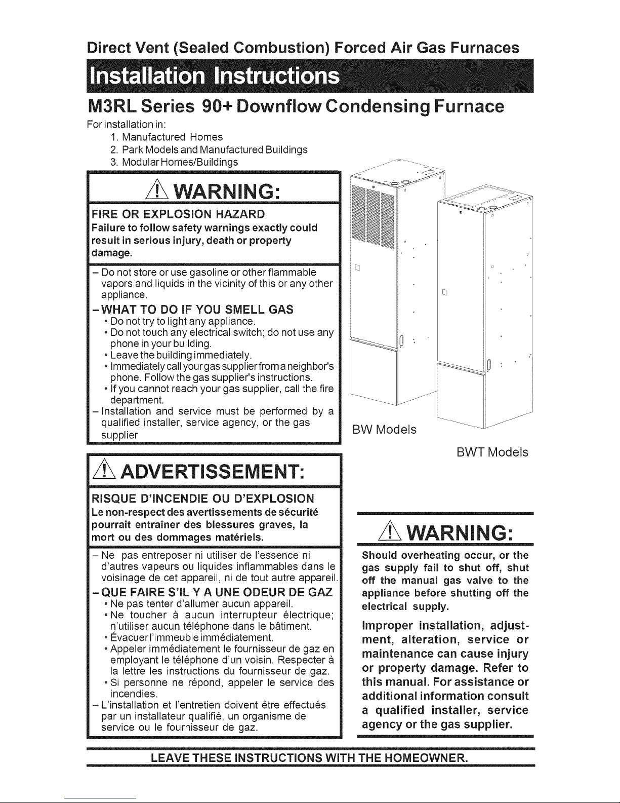
Direct Vent (Sealed Combustion) Forced Air Gas Furnaces
M3RL Series 90+ Downflow Condensing Furnace
For installation in:
1. Manufactured Homes
2. Park Models and Manufactured Buildings
3. Modular Homes/Buildings
WARNING:
FIRE OR EXPLOSION HAZARD
Failure to follow safety warnings exactly could
result in serious injury, death or property
damage.
- Do not store or use gasoline or other flammable
vapors and liquids in the vicinity of this or any other
appliance.
-WHAT TO DO IF YOU SMELL GAS
• Do not try to light any appliance.
• Do not touch any electrical switch; do not use any
phone in your building.
• Leave the building immediately.
• Immediately callyourgas supplierfrom a neighbor's
phone. Follow the gas supplier's instructions.
• If you cannot reach your gas supplier, call the fire
department.
-Installation and service must be performed by a
qualified installer, service agency, or the gas
supplier
BW Models
J
BWT Models
J
ADVERTISSEMENT:
RISQUE D'INCENDIE OU D'EXPLOSION
Le non=respect des avertissements de securite
pourrait entrainer des blessures graves, la
mort ou des dommages materiels.
- Ne pas entreposer ni utiliser de I'essence ni
d'autres vapeurs ou liquides inflammables dans le
voisinage de cet appareil, ni de tout autre appareil.
-QUE FAIRE S'ILYA UNE ODEUR DE GAZ
• Ne pas tenter d'allumer aucun appareil.
• Ne toucher a aucun interrupteur electrique;
n'utiliser aucun t61ephone dans le b_timent.
• €:vacuer I'immeuble immediatement.
•Appeler immediatement le fournisseur de gaz en
employant le tel6phone d'un voisin. Respecter
la lettre les instructions du fournisseur de gaz.
• Si personne ne repond, appeler le service des
incendies.
-L'installation et I'entretien doivent Ctre effectues
par un installateur qualifie, un organisme de
service ou le fournisseur de gaz.
LEAVE THESE INSTRUCTIONS WITH THE HOMEOWNER.
WARNING:
Should overheating occur, or the
gas supply fail to shut off, shut
off the manual gas valve to the
appliance before shutting off the
electrical supply.
Improper installation, adjust-
ment, alteration, service or
maintenance can cause injury
or property damage. Refer to
this manual. For assistance or
additional information consult
a qualified installer, service
agency or the gas supplier.

2

TABLE OF CONTENTS
General ...................................................... 4
Unit Dimensions .................................. 4
Shipping Weights ................................ 4
Furnace Specification ........................ 4
Air Flow Data ..................................... 4
Owner's information ................................ 5
installation Requirements ...................... 6
Location .............................................. 8
Clearance ........................................... 8
Circulating Air Supply .......................... 10
Return Air Provisions ............................ 10
Air Distribution Systems ...................... 11
Duct Connector Selection .................... 11
Duct installation .................................... 12
Venting and Combustion
Air Requirements .......................... 14
Venting Requirements .......................... 14
Vent Table ........................................ 15
Vent Pipe Material ............................ 16
Vent Pipe Length and Diameter ....... 16
Vent Pipe installation ........................ 16
Pipe Routing & Support .................... 16
Location of Outdoor Termination ..... 18
Horizontal Venting ............................ 18
Vertical Venting ................................ 19
Vent Freezing Protection ................. 19
Concentric Vent Termination ........... 20
Drainage of Condensate
From Furnace ................................ 20
Gas Supply and Piping ......................... 21
Leak Check ...................................... 22
High Altitude Derate ......................... 22
Pressure Switch ............................... 22
Conversion ............................................. 22
Lighting and Adjustment
of the Appliance ............................ 24
Electrical Wiring ..................................... 24
Line Voltage Wiring .......................... 25
Low Voltage Wiring .......................... 26
Ventilation ............................................... 26
Start-up and Adjustment ..................... 26
Start-Up Procedure ......................... 26
Shut Down Procedure ..................... 27
Verifying and Adjusting Firing Rate. 27
Temperature Rise ............................ 27
Verifying and Adjusting
Verifying Burner Operation .............. 28
Verifying Operation of the
Supply Air Limit Switch ................. 28
Description of Components ................ 29
Furnace Accessories ............................. 29
Maintenance ........................................... 29
Combustion Air and Vent System .... 29
Air Filter(s) ....................................... 29
Lubrication ........................................ 30
Condensate Drain Assembly ........... 30
Blower Compartment ....................... 30
Heat Exchanger and Burner
Maintenance .................................. 30
System Operation Information ............. 30
Sequence of Operation .................... 30
Furnace Fails to Operate ................. 31
Component Location ............................ 32
Wiring Diagram ....................................... 33
Installation/Performance
Checklist ......................................... 35
M3RL-060A-A W
Application
M-Manufactured Home
Furnace Series
Comfort Model
RL - Condensing Downflow
Heating Capacity
input, BTUH (000')
Table 1. Model Identification
LReturn Air Configuration
Blank- Front
L
T - Top
Door Color
W - White
G - Gray
Cabinet Dimensions
A - 56"x 19-3/4" x 23-3/4"
B - w/Coil Cavity,
76" x 19-3/4" x 23-3/4"
Electrical Code
A - 1PH, 60 Hz, 120 VAC
3

GENERAL
Top Return Knockouts
7/3243. I12
27-25/32
"B" Cabinet
-- 19-7/8 --
16
--3-17/32
COMBUSTION AIR INTAKE
--1-11/16
EXHAUST
VENT
Figure 1. Furnace Dimensions
--3-17/32
COMBUSTION AIR INTAKE
--1-11/16
EXHAUST
VENT
"A" Cabinet
"\ /
SIDE RETURN
KNOCKOUTS
/\
L--- ......_
_ 21-15/16--
m
_ _ 12.000
1,000
I
:
21.000
Y
Top View Top Returrl Opening
(AW and BW Models) (BWT Models)
Furnace Specifications / Airflow Data
Furnace Furnace Temp. External Static Pressure ( Inches Water Column)
Furnace Input Output
rVlodel No. Btuh Btuh
M3 RL-060 60,000 54,000
M3 RL-080 80,000 72,000
Rise @ Motor Motor 0.1 0.2 0.3 0.4
.3"WC °F HP Speed CFM CFM CFM CFM
35 - 65 1/2
35 - 65 1/2 Med-High 1512 1467 1416 1363
High* 1660 1599 1544 1474
Med-High 1512 1467 1416 1363
Med-Low 1340 1304 1261 1217
Low** 1176 1142 1108 1025
High* 1660 1599 1544 1474
Med-Low** 1340 1304 1261 1217
Low** 1176 1142 1108 1025
(
Shipping
Furnace Model Weight
(Ibs)
M3RL 060A AW 150
M3RL 060A BW* 170
M3RL 080A AW 155
M3RL 080A BW* 175
* May include suffix - T
Table 2. Shipping Weight
Recommended
0.5 A/C
CFM Ton
1410 4
1304 3
1158 2.-1/2
966 2
1410 4
1304 3
1158 2.-1/2
966 2
Note: Data is for Operation with Filter. * Factory Wired Cooling Tap
Table 3. Furnace Specifications/Airflow Data
4
•* Factory Wired Heating Tap
/ WARNING:
Do not use this appliance if any part
has been submerged underwater, im-
mediately call a qualified service tech-
nician to inspect the appliance and to
replace any part of the control system
and any gas control that has been
submerged underwater,
NOTICE TO INSTALLER
Installer is advised to follow carefully all instruc-
tions and warnings in this manual to insure
maximum performance, safety, and operating
efficiency ofthese appliances. Improper installa-
tion may create hazardous conditions, and will
void the appliance warranty.
GENERAL
General Description
The M3 series gas furnaces are listed direct
vent (sealed combustion) forced air furnaces
for use with both natural and propane gases.
The M3 series is a Category IV and type FSP
furnace. The M3 furnace series has been
certified to the ANSI Z21.47/CSA2.3-2001 for
use in the United States and Canada and to the
UL307B --1995 for use in the United States.
5. Never test for gas leaks with an open
flame. Use a commercially available soap
solution made specifically for the detection
of leak to check all connections.
6. Always install furnace to operate within the
furnace's intended temperature rise range
with a duct system that has an external
static pressure within the allowable range,
as specified in page 4 of these instruc-
tions. See Table 3 and the furnace rat-
ing plate.
7. When a furnace is installed so that supply
ducts carry air circulated by the furnace to
areas outside the space containing the
furnace, the return air shall also be handled
by duct(s) sealed to the furnace casing
and terminating outside the space contain-
ing the furnace. Note: This section only
applies to furnaces installed with side or
top return air.
8. A gas4ired furnace for installation in a
residential garage must be installed as
specified in page 9 of these instructions.
9. The furnace is not to be used for tempo-
rary heat of buildings or structures under
construction.
M3 series furnaces are air conditioning ready
as shipped. The furnace cooling capacities of
the blower motor speed taps are shown in
Table 3. Table 2 lists the shipping weights for
the M3 series furnaces.
These furnaces may be installed in:
1. Manufactured Homes.
2. Park Models and Manufactured buildings
3. Modular Homes/Buildings
The following are safety guidelines with refer-
ences to their specific sections or pages in the
manual.
1. Use only type of gas approved for this
furnace. Refer to the furnace rating plate.
2. Install this furnace only in location and
position as specified in pages 8 - 14 of
these instructions.
3. Provide adequate combustion and ventila-
tion air to the furnace space as specified in
pages 13 - 20 of these instructions.
4. Combustion products must be discharged
outdoors, connect this furnace to an ap-
proved vent system only, as specified in
pages 14-20 of these instructions.
OWNER INFORMATION
NORDYNE has been involved in the design of
products for the manufactured home industry
since the first manufactured home or trailer
was built.
NORDYNE originated the sealed combustion
system, which separates the furnace com=
bustion system from the living area of the
home, now a standard for the manufactured
home industry.
NORDYNE engineers developed the first cen-
tral heating system and the first central air
conditioner for manufactured homes.
NORDYNE is dedicated to bringing to its cus=
tomers the finest heating and cooling comfort
possible. NORDYNE constantly seeks to fur=
ther refine its products to continuously provide
exceptional comfort.

Followtheinstructionsinthisbookletcarefully
andthisappliancewillprovidemanyyearsof
superiorperformance.
If youwishto coolyour homeautomatically
witha centralairconditioningsysteminvesti-
gatetheexcellentNORDYNEcoolingsystems
availablefromyourheatingandcoolingcon-
tractor.Thesesystemsaredesignedto work
bestwithyourNORDYNEfurnaceand have
beencarefullyengineeredto deliveroptimum
performancewhen matedwith NORDYNE
manufacturedhomefurnaces.
NORDYNEalsoofferswaterheaters,fireplaces
and ventilatingsystemsspecificallydesigned
for manufacturedhousingapplications.Check
with your manufacturedhomeretailer,your
heating and cooling contractor or your
distributorfor information.Writedirectlyto the
factory8000PhoenixParkway,O'Fallon,MO
63368ifyouarenotabletolocateasourcefor
NORDYNEmanufacturedhousingproductsin
yourarea.
MANUFACTURER WARRANTY, OWNER'S
RESPONSIBILITIES
It is the sole responsibility of the homeowner to
make certain the gas furnace has been correctly
set up and converted to the proper fuel (L.P. gas
or Natural gas) and adjusted to operate prop-
erly. All gas furnaces are manufactured for
Natural gas and must be field converted when
using LP. gas.
A warranty certificate with full details is included
with these instructions. However, NORDYNE
will not be responsible for any costs found nec-
essary to correct problems due to improper
setup, improper installation, furnace adjustments,
improper operating procedure on the part of the
user, etc.
Some specific examples of service calls which
cannot be included in warranty payments are:
1. Converting the furnace to use another type
of gas.
2. Repairing ductwork in the home found to be
faulty.
3. Correcting wiring problems in the electrical
circuit supplying the furnace.
4. Resetting circuit breakers, blown fuses or
other switches.
5. Correcting problems due to improper gas
supply pressure to the furnace.
6. Providing instructional training on how to
light and operate the furnace.
7. Furnace problems caused by installation of
an air conditioner, heat pump or other air
comfort devices.
8. Revising installation of the furnace flue
assembly.
9. Adjusting or calibrating of thermostat.
10. Any construction debris which falls into
the flue system.
Carefully review these responsibilities with your
manufactured housing dealer, service company
or gas supplier so there will be no misunder-
standing at a later time.
CAUTION:
• Never attempt to alter or modify this
furnace or any of its components.
• Never attempt to repair damaged or
inoperable components. Such action
could cause unsafe operation, ex-
plosion, fire and/or asphyxiation.
• If a malfunction has occurred, or if
you feel that the furnace is not oper-
ating as it should, contact a qualified
service agency or gas utility for as-
sistance.
INSTALLATION STANDARDS
Installer shall be familiarwith and complywith all
codes and regulations applicable to the installa-
tion of these heating appliances and related
equipment. In lieu of local codes, the installation
shall be in accordance with the current provi-
sions of one or more of the following standards.
a. Federal Manufactured Home Constructions
& Safety Standard (H.U.D. Title 24, Part
3280.707[a][2])
b. The Standard for Manufactured Home Instal-
lations (Manufactured Home Sites, Commu-
nities, and Set-Ups) ANSI A225.1 and/or
CAN/CSA-2240 MH Series).
c. American National Standard (ANS1=119.2/
NFPA=501C) for all recreational vehicle in-
stallations.
d. American National Standard (ANSI=Z223.1/
NFPA-54) and/or CAN/CGA B149 for all gas-
fired furnace models.
e. American National Standard (ANSI=C1/NFPA-
70) and/or CSA 22.1 Canadian Electric Code
Part 1 for all electrical field wiring.
6

CE g6nerateurd'air chauddoitCtreinstalle
conformementauxinstructionsdufabricantet
auxcodesIocaux.EnI'absencedecodelocal,
respecterlanormeANSIZ223.,1,instituleNa-
tionalFuelGasCodeoulescodesd'installation
CAN/GCA-B149.
the side wall horizontal vented gas fueled
equipment. It shall be the responsibility of the
property owner to secure the services of
qualified licensed professionals for the
installation of hard wired carbon monoxide
detectors.
The National Fuel Gas Code is available by
writing:
American National Standards Institute, Inc.
1430 Broadway
New York, NY 10018
NFPA publications are available by writing:
National Fire Protection Association
Batterymarch Park
Quincy, ME 02269
IMPORTANT NOTE
INSTALLATION REQUIREMENTS =
COMMONWEALTH OF
MASSACHUSETTS
The Commonwealth of Massachusetts
requires compliance with regulation 248 CMR
5.00 for installation of the side wall horizontal
venting. The following requirements shall be
satisfied.
INSTALLATION OF CARBON
MONOXIDE DETECTORS
At the time of installation of the side wall
horizontal vented gas fuel equipment, the
installing plumber or gasfitter shall observe
that a hard wired carbon monoxide detector
with an alarm and battery back-up is installed
on the floor level where the gas equipment is
to be installed. In addition, the installing plumber
or gasfitter shall observe that a battery operated
or hard wired carbon monoxide detector with
an alarm is installed on each additional level of
the dwelling, building or structure served by
ALL MODELS
Front
Back
Sides
Vent
Top
Duct (Plenum)
w/Coil Box
w/o Coil Box
(within 3 feet)
*Note: For 1" clearance, use a fully Iouvered door with at least
400 square inches of free airflow area.
CLOSET
Inches
1/4
Table 4. Minimum Clearances
ALC OVE
Inches
1"
0
0
0
6
0
1"
0
0
0
6
0
1/4
In the event that the side wall horizontally
vented gas fueled equipment is installed in a
crawl space or an attic, the hard wired carbon
monoxide detector with alarm and battery
back-up may be installed on the next adjacent
floor level.
In the event that the requirements of this
subdivision can not met at the time of completion
of installation, the owner shall have a period of
thirty (30) days to comply with the above
requirements; provided, however, that during
said thirty (30) day period, a battery operated
carbon monoxide detector with an alarm shall
be installed.
APPROVED CARBON MONOXIDE
DETECTORS
Each carbon monoxide detector as required in
accordance with the above provisions shall
comply with NFPA 720 and be ANSI/UL 2034
listed and IAS certified.
SIGNAGE
A metal or plastic identification plate shall be
permanently mounted to the exterior of the
building at minimum height of eight feet above
grade directly in line with the exhaust vent
terminal for the horizontally vented gas fueled
heating appliance or equipment. The sign shall
read, in print size no less than one-half (1/2)
inch in size, "GAS VENT DIRECTLY BELOW.
KEEP CLEAR OF ALL OBSTRUCTIONS."
INSPECTION
The state or local gas inspector of the side wall
horizontally vented gas fueled equipment shall
not approve the installation unless, upon
inspection, inspector observes carbon
monoxide detectors and signage installed in
accordance with the provisions of 248 CNR
5.08(2)(a) 1 through 4.
Exemptions: The following equipment is
exempt frolTl 248 CMR 5.08(2)(a) 1 through 4:
Product approved side wall horizontally vented
f_eled equipment installed in room or structure
separated from the dwelling, building or
structure used in whole or in part for residential
purposes.

MANUFACTURERREQUIREMENTS-
GASEQUIPMENTVENTINGSYSTEM
NOT PROVIDED.
When the manufacturer of a Product Approved
side wall horizontally vented gas fueled
equipment does not provide the parts for
venting the flue gases, but identifies" special
venting systems", the following requirements
shall be satisfied by the manufacturer:
1. The reference "special venting
system" instructions shall be
included with the appliance or
equipment instructions; and
2. The "special venting systems" shall
be Product Approved by the board,
and the instructions for that system
shall include a part list and detailed
installation instructions.
A copy of all installation instructions for all
Product Approved side wall horizontally vented
gas fueled equipment, all venting instructions,
all parts lists for venting instructions, and/or all
venting design instructions shall remain with
the appliance or equipment at the completion
of the installation.
LOCATION
The furnace must be installed on a level sur-
face, and as close to the center of the air
distribution system as possible. See Figure 1
for overall dimensions to determine the required
clearances in hallways, doorways, stairs, etc.
to allow the furnace to be moved to the instal=
lation point. The furnace must be installed so
that all electrical components are protected
from water.
Minimum clearances to combustible materials
are listed in Table 4. Access for positioning and
servicing must be considered when locating the
unit.
This furnace is certified for use on wood floor=
ing. The furnace must be installed on a solid
surface and must be level front-to-back and
Top View
of Duct
Connector
A Single trunk duct
, D
_" Dual trunk duct
B w/crossover connector
I
Transition duct
C [p w/branches [']____[1_
Figure 2. Non-Platinum
7
II II II
Supply Duct System
FLOOR CAVITY
(depth equal to "X" in Table 5)
I I
Figure 4. Connector Dimensions
Use Duct Connector
If "X" (Floor Cavity)is: Model Part Number:
English Metric (mm) Finger Tab ScrewDowr
7/8" 22 901987 904008
2" 51 901988 904009
4 1/4" 108 901989 904010
6 1/4" 150 901990 904011
8 1/4" 210 901991 904012
10 1/4" 260 901992 904013
12 1/4" 311 901993 904014
Table 5. Duct Connector Sizes
8
Figure 3. Floor Cavity

REDUCER _\
FELT-SEAL
SPACERS
(1) FINGER TAB DUCT CONNECTOR ONLY
(2) SCREW DOWN DUCT CONNECTOR ONLY
Figure 5. Duct Connector
side=to=side. This furnace must not be installed
directly on carpeting, tile, or any combustible
material other than wood flooring. The furnace
may be installed on combustible flooring when
installed on a Nordyne duct connector (see
Table 5).
The ductwork within 3 feet of the furnaces
without the A/C coil box must be installed such
that surfaces are at least 1/4" from combustible
materials.
,&
X SEE
TABLE 5
( )OPENING TO DUCT
(1) WITH PLATE (C) REMOVED
OPENING BECOMES
13-1/4" x 13-1/4"
(2) WITH PLATE (C) REMOVED
OPENING BECOMES
13"X 13". WITH REDUCER
IT IS 13"X 10-1/8",
When installed in a residential garage, the fur=
nace must be positioned so the burners and the
source of the ignition are located no less than
18 inches above the floor and protected from
physical damage by vehicles.
F I 142-_/2 _ 2-3/4'_
_/////_.REAR WALL OF CLOSET bR_,_co_E_
2-1/4
F F LRODOuRc_UT-oONUNTECT i O N S
14-1/2
3-1/4
-3/4
fl ....
' 1-1/4 / I _ 12-7/8
ALT FUEL LINE / !. _ !__q,_
24
ENTRY /' / ..... I
_,, _ 15-1/2 _
i I
I
_- FLOOR CUT-OUT
FOR OPTIONAL
COOLING COIL
FOR NON-PLATINUM
SERIES UNITS
lO"
FLo2
23-1/4"
HOLE \\\\\
Figure 6. Closet or Alcove
g
17-29/32
u_
-- 3-19/32
-- 1-3/4
_- VENT
COMBUSTION AIR INTAKE
J
_-- FUEL LINE ENTRY
2
_ 1-3/4
FURNACE
OUTER DOOR
21-7/16
Figure 7. Floor Cut-Out Dimensions
9

CIRCULATING AiR SUPPLY
z WARNING:
Products of combustion must not be
allowed to enter the return air openings
of the furnace or the circulating air
supply, Failure to prevent products of
combustion from being circulated into
the living space can create potentially
hazardous conditions including carbon
monoxide poisoning that could result in
personal injury or death,
The floor or platform on which the furnace
ismounted must provide sound physical
support of the furnace with no gaps,
cracks, or sagging between the furnace
and the floor or platform,
The circulating air ductwork must not be
connected to any other heat producing
device such as a fireplace insert, stove,
etc,
GENERAL
Plenums and air ducts must be installed in
accordance with the Standard for the Installa-
tion of Air Conditioning and Ventilating Systems
(NFPA No. 90A) or the Standard for the Instal-
lation of Warm Air Heating and Air Conditioning
Systems (NFPA No. 90B).
RETURN AIR PROVISIONS
U.S.A. home manufacturers shall comply with
all of the following conditions to have accept-
able return air systems for closet installed
forced air heating appliances:
a. Regardless of the location, the return air
opening into the closet shall not be less than
specified in the appliance's listing.
b. Means shall be provided to prevent inadvert-
ent closure by a flat object placed over the
return air opening when it islocated in the floor
of the closet (versus the vertical front or side
wall).
c. Closet installations must use a Iouvered door
having a minimum free area of 235 sq. in.
when located 6" from furnace. For clearance
between 1" and 6" from furnace, require-
ments are a Iouvered door with minimum of
235 sq. in. free area, with the openings in
closet door directly inline with the Iouvered
openings in the furnace door. For 1" clear-
ance from furnace, use a fully Iouvered door
with at least 400 sq. in. of free airflow area.
d. The cross-sectional area of the return duct
system leading into the closet, when located
in the floor or ceiling shall notbe less than 235
square inches.
e. The total free area of openings in the floor or
ceiling registers serving the return air duct
system must be at least 352 sq. in. At least
one register should be located where it is not
likely to be covered by carpeting, boxes and
other objects.
f. Materials located in the return duct system
must have a flame spread classification of
200 or less. This includes a closet door if the
furnace is in a closet.
g. Noncombustible pans having 1" upturned
flanges are located beneath openings in a
floor duct system.
h. Wiring materials located in the return duct
system shall conform to Articles 300-22 of
the National Electrical Code (ANSI Cl/
NFPA-70).
i. Gas piping is not run in or through the return
duct system.
j. Test the negative pressure in the closet with
the air-circulating fan operating at high speed
and the closet closed. The negative
pressure is to be no more negative than
minus 0.05 inch water column.
k. For floor return systems, the manufactured
home manufacturer shall affix a prominent
marking on or near the appliance where itcan
be easily read when the closet door is open.
The marking shall read:
CAUTION:
HAZARD OF ASPHYXIATION: Do not
cover or restrict return air opening,
I. Air conditioning systems may require more
duct register and open louver area to ob-
tain necessary airflow. Use NORDYNE's
certiduct program to determine proper duct
size for A/C.
10
DUCTEDRETURNAIR
M3furnaceswithmodelnumbersendinginAW
orBWarefactoryconfiguredfor thereturnair
to flowthroughthefrontIouvereddoor.The
returnairmayalsobeattachedtoeithersideor
the top of the furnacecabinetusinga field
installedkit.RefertoTable10fortheNORDYNE
ductedreturnkitP/Nnumber.Thelocationand
sizeof thesideandtopreturnairconnections
areshowninFigure1.Thefiltersizefortheside
returnairis20"x20"x1".Fortopreturnthefilter
sizeis24"x 16"x 1".
M3furnaceswithmodelnumbersendingin
BWTarefactoryconfiguredforthereturnairto
enterthetopofthefurnace.
AIR DISTRIBUTION SYSTEMS
For proper air distribution, the supply duct
system must be designed so that the static
pressure measured external to the furnace
does not exceed the listed static pressure
rating shown on the furnace rating plate.
Three typical distribution systems are illus-
trated in Figure 2. Location, size, and number
of registers should be selected on the basis of
best air distribution and floor plan of the home.
DUCT CONNECTOR SELECTION
PLATINUM SERIES
a. For Platinum ready construction use
the 14" round plenum, p/n: 903896.
NON=PLATINUM SERIES
a.
Determine depth of floor cavity from
surface of floor to top of supply air duct
(See Figure 3).
b.
Select appropriate model from Table 5
which matches X-dimension of the floor
cavity. To maximize air delivery, re-
move reducer "C" (see Figure 5) to
obtain the largest open area that will fit
the duct/floor construction.
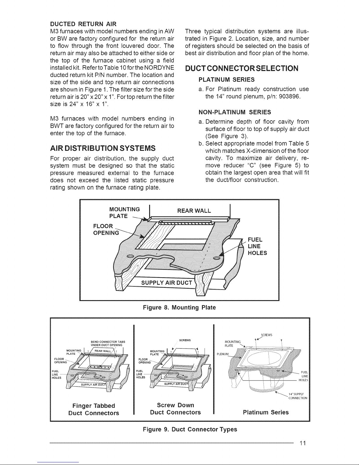
MOUNTING
PLATE
FLOOR
OPENING
BEND CONNECTOR TABS
UNDER DUCT OPENING
REAR WALL
SUPPLY AIR DUCT
Figure 8. Mounting Plate
MOUNTING
PLATE
FUEL
LINE
HOLES
SCREWS
Finger Tabbed
Duct Connectors
Screw Down
Duct Connectors
Figure 9. Duct Connector Types
CONNECTION
Platinum Series
11
 Loading...