

Nordyne M2RC-080, M2RC-100, M2RL-060, M2RL-100 Installation Instructions Manual
Direct Vent (Sealed Combustion) Forced Air Gas Furnaces
M2RC Series 90+ Upflow Condensing Furnace
M2RL Series 90+ Downflow Condensing Furnace
Upflow Model
/ WARNING:
Improper installation, adjustment,
alteration, service, or maintenance
can cause injury or property damage.
Refer to this manual for assistance.
For additional information consult a
qualified installer, service agency, or
the gas supplier.
Do not store or use gasoline or
other flammable vapors and
liquids in the vicinity of this or
any other appliance.
Downflow Model
Do not try to light any appliance.
Do not touch any electrical
switch; do not use any phone in
your building,
Immediately call your gas supplier
from a neighbor's phone. Follow
the gas supplier's instructions.
if you cannot reach your gas
supplier, call the fire department.
Extinguish any open flame.
WARNING: Danger. Only qualified service
personnel shall be used to install and provide
maintenance to this appliance.
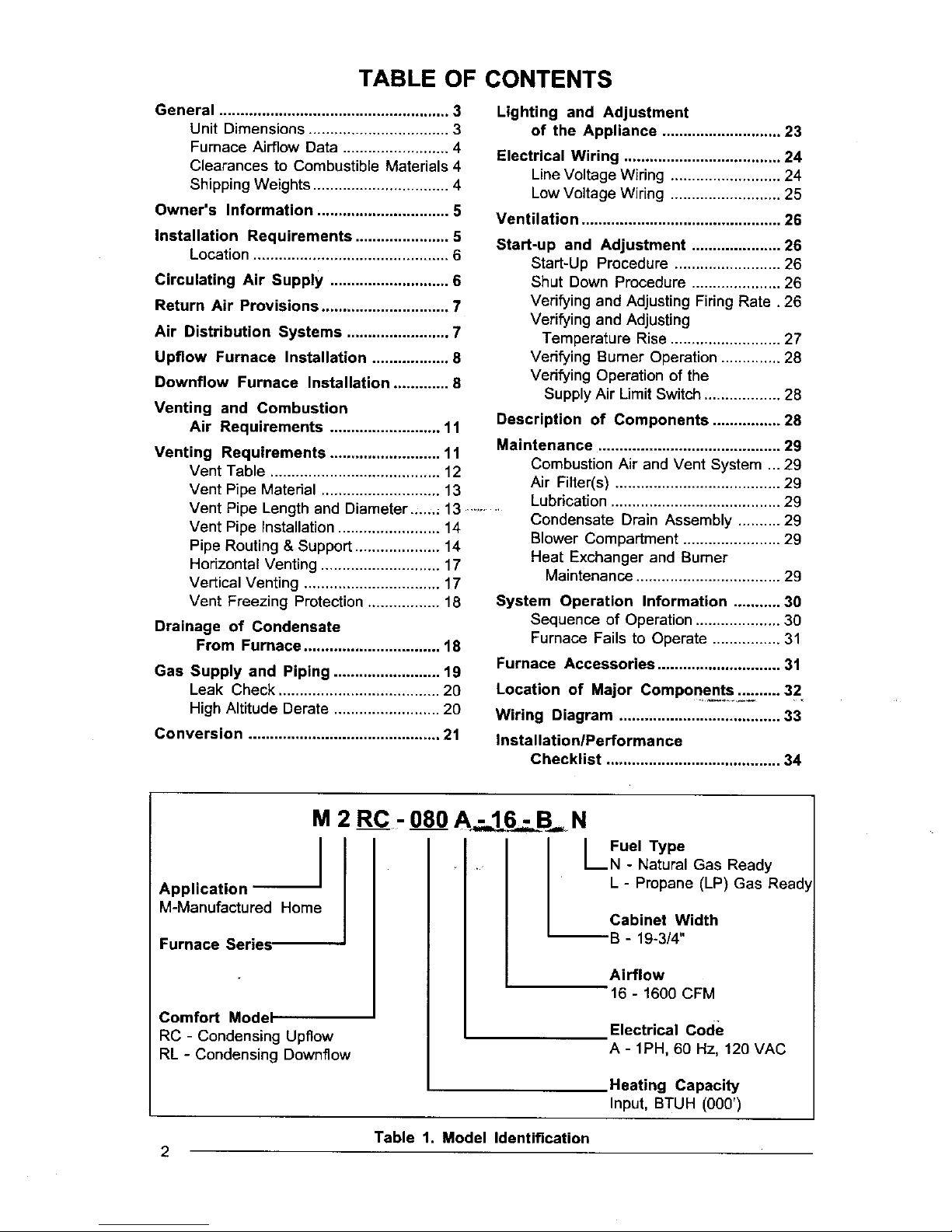
TABLE OF CONTENTS
General ...................................................... 3
Unit Dimensions ................................. 3
Furnace Airflow Data ......................... 4
Clearances to Combustible Materials 4
Shipping Weights ................................ 4
Owner's Information ............................... 5
Installation Requirements ...................... 5
Location .............................................. 6
Circulating Air Supply ............................ 6
Return Air Provisions .............................. 7
Air Distribution Systems ........................ 7
Upfiow Furnace Installation .................. 8
Downflow Furnace Installation ............. 8
Venting and Combustion
Air Requirements .......................... 11
Venting Requirements .......................... 11
Vent Table ........................................ 12
Vent Pipe Material ............................ 13
Vent Pipe Length and Diameter....., 13 .........
Vent Pipe Installation ........................ 14
Pipe Routing & Support .................... 14
Horizontal Venting ............................ 17
Vertical Venting ................................ 17
Vent Freezing Protection ................. 18
Drainage of Condensate
From Furnace ................................ 18
Gas Supply and Piping ......................... 19
Leak Check ...................................... 20
High Altitude Derate ......................... 20
Conversion ............................................. 21
Lighting and Adjustment
of the Appliance ............................ 23
Electrical Wiring ..................................... 24
Line Voltage Wiring .......................... 24
Low Voltage Wiring .......................... 25
Ventilation ............................................... 26
Start-up and Adjustment ..................... 26
Start-Up Procedure ......................... 26
Shut Down Procedure ..................... 26
Verifying and Adjusting Firing Rate. 26
Verifying and Adjusting
Temperature Rise .......................... 27
Verifying Burner Operation .............. 28
Verifying Operation of the
Supply Air Limit Switch .................. 28
Description of Components ................ 28
Maintenance ........................................... 29
Combustion Air and Vent System ... 29
Air Filter(s) ....................................... 29
Lubdcation ........................................ 29
Condensate Drain Assembly .......... 29
Blower Compartment ....................... 29
Heat Exchanger and Burner
Maintenance .................................. 29
System Operation Information ........... 30
Sequence of Operation .................... 30
Furnace Fails to Operate ................ 31
Furnace Accessories ............................. 31
Location of Major Components._._ '...... 32
Wiring Diagram ...................................... 33
Installation/Performance
Checklist ......................................... 34
M 2 RC.- 080 N
IFuel Type
• I_N - Natural Gas Ready
Application
M-Manufactured Home
Furnace Series,
Comfort Model
RC - Condensing Upflow
RL - Condensing Downflow
L - Propane (LP) Gas Read_
Cabinet Width
--B - 19-3/4"
Airflow
16 - 1600 CFM
Electrical Code
A - 1PH, 60 Hz, 120 VAC
Heating Capacity
Input, BTUH (000')
Table 1. Model Identification
2

GENERAL
Upflow Furnace
Cover
Plate
Combusbon Air
Inlet J_l Combustion
23 1'4"
-- Airln_et --
L /
1 3/8"
2 t,4" Condensate
4-- Drain Outlet
6 114"
_.: rt
r7
9 n
Bottom Ream
Opening
-- 19 314"_
Exhaust
Vent
A/C Coil Box
--27 5,8"
Gas Connection
Condensata
Drain Outlet
Downflow Furnace
i
Combust;cm Air Inlet I
i
'_ i I Exhaul_ , .
_,-_ : -_,
i
2
_l_ 24 718"
1 I/2" T
21 114"_ t5t/2.
°+,,,,o.
1111llt@
,(-_ 19 3/4" _1
Norton Supply Air O_0emng
10_
k_ 8UpldyAk
O_nm.g
(S_ I
Sl/4'
Bottom Supply AtrOpen nt
I-3/4-
Combustion
Air Inlet
RetumAirOpenln
-- 27 718"--
, Y
718" Die
Electric
Connection
"_" 11/2. x 2 tl2 .
?
21 1/2"
Figure 1. Unit Dimensions
3

IMPORTANT:READALL INSTRUCTIONS
CAREFULLYBEFOREBEGINNINGTHE
INSTALLATION.
/ WARNING:
Do not use this product if any part has
been submerged under water.
Immediately call a qualified service
technician to inspect the appliance and
to replace any part of the control system
and any gas control that has been
submerged under water.
ifiedservice technician periodically check allwiring
connections and service unit as required.
The M2 sedes gas furnaces are listed drect vent
(sealed combustion) forced air furnaces (type
FSP) for use with both natural and propane (LP)
gases. The M2 furnace series has been certi-
fied tothe UL 307B standard for use in the United
States and to ANSI Z21.47a-CAN/CGA-2.3a-
1995 for use in the United States and Canada.
These furnaces may be installed in:
1. Manufactured Homes
2, Recreational Vehicles, Park Models
3. Manufactured Buildings
/ WARNING:
Should overheating occur, or the gas
fail to shut off, shut offthe manual gas
valve to the appliance before shutting
off the electrical supply.
NOTICE: Leave these instructions withthe home-
owner. Advise unit owner/user to follow the main-
_ter]ance rrecommendations outlined. Have a qual-
4. Modular Homes / Buildings
The M2 furnace is not to be used for the tempo-
rary heating of buildings under construction.
Model Shipping Weight (Ibs)
M2RC -080A * 16- B_*) 160
M2RC - 1OOA- 16 - S(*) 170
M2RL - O60A- 16 - B(*) 170
M2RL - 080A - 16 - B(*) 170
M2RL - 100A - 16 - B(*) 175
A]C Coil Box 20
•Can be N orL
Table 2. Shipping Weights
CAPACITIES --Furnace Airflow Data
Furnace
Furnace input Motor _oto; 0.t
Model No. B_uh Speed HP CFM Rise
High * 1840 *
M2RO-OSO 80,000 Meal-High 1/2 1600 43
Med-Lcw *' 1380 50
Low 1100
High * 1910 -
M2RC-100 100,000 Meal-High " 1640 53
Med-Low 1/2 1440 61
Low 1230 -
High * 1620 32
Med High 1450 36
M2RL_60 60,000 Med Low *' 1/2 1255 42
Low 1080 48
High" 1620 43
Med High 1450 49
M2R L-089 8_,000 Med Low_ 1/2 1255 56
L_ 1080 65
High* 1620 54
Meal High " 1430 62
M2RL-100 100,000 Med Low 112 1260 70
Low 1085
• Factorywired cc_ling speed tap
•* Factory wired heatingspeed tap
Exkrnal stage Pr,_sure (Inches Water Column}
0.2 0.3 0.4 0.5
CFM I_se CFM Rise CFM Rise CFM Rise
1780 - 1700 - 1630 - 1550 -
1560 44 1470 47 1400 49 1350 51
1350 51 1300 53 1250 55 1190 58
1050 1000 950 900
1860 - 1780 - 1700 - 1620 -
1620 54 1540 57 1480 59 1420 62
1410 62 1370 64 1320 66 1270 70
1210 - 1180 - 1140 . 1090 -
1560 33 1490 35 1430 36 1365 38
1400 37 1350 38 1295 40 1240 42
1225 43 1180 44 1145 45 1105 47
1055 49 1030 51 1000 52 960 54
1560 45 1490 47 1430 49 1365 52
1400 50 1350 52 1295 54 1240 57
1225 57 1180 60 1145 61 1105 64
1055 67 1030 68 1000 70 960 73
1555 57 1485 59 1425 62 1355 65
1375 64 1330 66 1265 70 1210 73
1220 72 1170 75 1130 1070
1050 1015 970 935
- NotRecommended
Table 3.
NOTE:Dataisfor operationwfthfilter.
Furnace Airflow Data
CLEARANCES TO COMBUSTIBLE MATERIALS
Thisfurnace is designedfor the minimum clearancesto combustiblematerial listed in Table 4. Refer
tothe fumace name plate, locatedinside the furnacecabinet,for specificmodel numberand clearance
information. Furnace Cabinet Minimum Clearances (Inches}
Input Width Plenum Ductwork within
(Stuh} flnches_ Side Vent Back Top* Front** Surfac_ 3 fL of Furnace
60,000 19314 O O 0 10 0 1/4 1/4
80,000 193/4 O O O 10 O 1/4 1/4
100,000 193/4 0 O 0 19 0 1/4 , 1/4
* For Downflow model only.Upflow modelscan be 1".
** 24 inches isthe minimum clearance for servicing. 36 inches is the recommended clearance for service.
Table 4. Minimum Clearances to Combustible Materials
4

NOTICE TO INSTALLER
Installer is advised to follow carefully all in-
structions and warnings in this manual to in-
sure maximum performance, safety, and oper-
ating efficiency of these appliances. Improper
installation may create hazardous conditions,
and will void the appliance warranty.
Manufacturer Warranty, Owner's
Responsibilities
It is the sole responsibility of the homeowner to
make certain the gas furnace has been cor-
rectly installed in the home, converted to the
proper fuel (LP gas or Natural gas), and ad-
justed for proper operation.
OWNER'S INFORMATION
About Your Central Furnace System
NORDYNE has been involved in the design of
products for the manufactured home industry
since the first manufactured home or trailer
was built.
NORDYNE originated the sealed combustion
system, which separates the furnace com-
bustion system from the living area of the home
and is now a standard for the manufactured
home industry.
NORDYNE engineers developed the first cen-
tral heating system and the first central air
conditioner for manufactured homes.
NORDYNE is dedicated to bringing to its cus-
tomers the finest heating and cooling comfort
possible. NORDYNE constantly seeks to fur-
ther refine its products to continuously provide
exceptional comfort.
A warranty certificate with full details is in-
cluded with this furnace. However, NORDYNE
will not be responsible for any costs found
necessary to correct problems due to im-
proper setup, improper installation, furnace
adjustments, improper operating procedure
on the part of the user, etc.
Some specific examples of service calls which
cannot be included in warranty payments are:
1. Converting the furnace to use another
type of gas.
2. Repairing duct work in the home found to
be faulty.
3. Correcting wiring problems in the electri-
cal circuit supplying the furnace.
4. Resetting circuit breakers, blown fuses
or other switches.
5. Correcting problems due to improper gas
supply pressure to the furnace.
6. Providing instructional training on how to
light and operate the furnace.
7. Correcting any problems caused by in-
stallation of an air conditioner, heat pump
or other air comfort devices.
Follow the instructions in this booklet carefully 8. Revising installation of the furnace flue
and this appliance will provide many years _of ......... assembly: ..............................
superior performance. 9. Adjusting or calibrating of thermostat.
Ifyou wish to cool your home automatically with
a central air conditioning system investigate
the excellent NORDYNE cooling systems avail-
able from your heating and cooling contractor.
These systems are designed to work best with
your NORDYNE furnace and have been care-
fully engineered to deliver optimal performance
when mated with NORDYNE manufactured
home furnaces.
NORDYNE also offers water heaters, fire-
places and ventilating systems specifically
designed for manufactured housing applica-
tions. Ask your manufactured home retailer,
10. Removing any construction debris which-
has fallen into flue system.
Carefully review these responsibilities with
your manufactured housing dealer, service
company, or gas supplier, so that there will be
no misunderstanding at a later time.
INSTALLATION REQUIREMENTS
Requirements and Codes:
The installer must be familiar with and comply
with all local codes and regulations applicable
to the installation of heating appliances and
related equipment. In the absence of local
your heat nn and coolin,_ contractor or your codes, the installationmust conform with these
distributor for more information. Write directly instructions and the current provisierfs_'6f_one
to the factory (PO Box 46911, St. Louis, MO or more of the following standards:
63146) if you are unable to locate a source for a. Federal Manufactured Home
NORDYNE manufactured housing products in Constructions & Safety Standard (H.U.D.
your area. Title 24, Part 3280.707[a][2])
b. The Standardfor ManufacturedHome
Installations (Manufactured Home Sites,
Communities, and Set-Ups)ANSI A225.1
and/or CAN/CSA-2240 MH Series).
c. American National Standard (ANSI-
119.2/NFPA-501C) for all recreational
vehicle installations.
d. American National Standard (ANSI-
Z223.1/NFPA-54) and/or CAN/CGA
B149 for all gas-fired furnace models.
e. American National Standard (ANSI-C1/
NFPA-70) and/or CSA 22.1 Canadian
Electric Code Part 1 for all electrical field
wiring.
CE g6nerateur d'air chaud dolt 6tre insta]l_
conform6ment aux instructions du fabricant et
aux codes Iocaux. En I'absence de code local,
respecter la norme ANSI Z223.,1, institule Na-
tional Fuel Gas Code ou les codes d'installation
CAN/GCA-B 149.
The National Fuel Gas Code is available by
writing:
able and allow the appropriate clearance for
your installation.
This furnace is certified for use on wood
flooring. The furnace must be installed on a
solid surface and must be level front to back
and side to side. This furnace must not be
installed directly on carpeting, tile, or any
combustible material other than wood flooring.
Downflow models can only be installed on
combustible flooring when installed on a
Nordyne plenum base (part numbers 901987
through 901993 - see Table 5). Both the upflow
and downflow models must be installed with
the Nordyne A,'C coil box (part no. 914958).
The plenum attached to the A,'C coil box and
the ductwork within 3 feet of the furnace must
be installed such that surfaces are at least
1/4" from combustible construction.
CIRCULATING AIRSUPPLY
General
Plenums and air ducts must be installed in
AmericanNationaIStandardslnstitute,lnc. ' accordance with the Standard for the
1430 Broadway Installati0n of Air Conditioning and Ventilating
New York, NY 10018 Systems (NFPA No. 90A) or the Standard for
the Installation of Warm Air Heating and Air
NFPA publications are available by writing: Conditioning Systems (NFPA No. 90B).
National Fire Protection Association
Batterymarch Park
Quincy, ME 02269
Location
The furnace must be installed on a level sur-
face, and as close to the center of the air
distribution system as possible. See Figure 1
for overall dimensions to determine the re-
quired clearances in hallways, doorways, stairs,
etc. to allow the furnace to be moved to the
installation point. The furnace must be installed
so that all electrical components are protected
from water.
Minimum clearances to combustible materials
are listed in Table 4. Access for positioning and
servicing must be considered when locating
the unit. 24 inches is the minimum required
clearance for servicing the unit. 30 inches isthe
minimum required clearance for positioning the
unit. 36 inches is the recommended clear-
ance from the front of the unit. Please note
that a panel or door can be located such that
the minimum clearance on the rating plate is
satisfied, but that panel or door must be remov-
/ WARNING:
Products of combustion must not be
allowed to enter the return air openings
of the furnace or the circulating airsupply,
Failure to prevent products of
combustion from being circulated into
the living space can create potentially
hazardous conditions including carbon
monoxide poisoning that could result in
personal injury or death.
The floor or platform on which the fumace
is mounted must provide sound physical
support of the furnace with no gaps,
cracks, or sagging between the furnace
and the floor or platform.
The circulating air ductwork must not be
connected to any other heat producing
device such as a fireplace insert, stove,
etc.

RETURN AIR PROVISIONS
Upfiow models draw the return air from the
base of the furnace. A stand or return air duct
must be supplied to the furnace to provide the
required return air.
Downflow models draw the return air from the
top of the furnace. The minimum required
clearance to the top of the furnace is detailed
on the furnace rating plate. Additional clear-
ance may be required depending upon filter
accessibility.
For each application, the U.S.A. home manufac-
turer shall comply with all of the following condi-
tions to have acceptable retum air systems for
closet installed forced air heating appliances:
a. Regardless of the location, the return air
opening into the closet shall not be less
than specified in the appliance's listing.
b. Means shall be provided to prevent
inadvertent closure by a flat object placed
over the return air opening when it is
located in the floor of the closet (versus
the vertical front or side wall).
c. The cross-sectional area of the return
duct system leading into the closet shall
not be less than 390 square inches.
d. The total free area of openings in the floor
or ceiling registers serving the return air
duct system must be at least 352 sq. in.
At least one register should be located
where it is not likely to be covered by
For floor return systems, the
manufactured home manufacturer shall
affix a prominent marking on or near the
appliance where it can be easily read
when the closet door is open. The
marking shall read:
CAUTION:
HAZARD OF ASPHYXIATION: Do not
cover or restrict return air opening.
k. Air conditioning systems may require
more duct, register and open louver area
to obtain necessary airflow. Use
NORDYNE's certiduct program to
determine proper duct size for A/C.
AIR DISTRIBUTION SYSTEMS
For proper air distribution, the supply duct
system must be designed so that the static
pressure measured external to the furnace
does not exceed the listed static pressure
rating shown on the furnace rating plate.
Three typical distribution systems are illustrated
in Figure 2. Location, size, and number of
registers should be selected on the basis of
best air distribution and floor plan of the home.
A Single trunk duct []
carpeting, boxes and other objects ............................................................
e. Materials located in the return duct
system must have a flame spread
classification of 200 or less. This includes
a-closetdo0r if theefu-rnac_ is"fna-cios_t._
f. Noncombustible panshaving 1"upturned
flanges are located beneath openings in
a floor duct system.
g. Wiring materials located in the return
duct,system shall conform_to Articles ,-
300-22 of the National Electrical Code
(ANSI CI/NFPA-70).
h. Gas piping is not run in or through the
return duct system.
i. Test the negative pressure in the closet
with the air-circulating fan operating at
high speed and the closet closed. The
negative pressure is to be no more
negative than minus 0.05 inch water
column.
BJ Dual trunk duct _ ]
- _ wlcrossover connector-_- •
J
U U U
Figure 2. Typical Supply Duct System
FLOOR CAVITY
U (depth equal to "X* in F3gure 5 and Table 5)
t JJJJJJJJJJJJJJJJJJJJJ JJ _ J Ji_
x-l--- -----.._ i l ,l
I I)J SuPPLYAiRoucT
-- I_! / k h\l
Figure 3. Floor Cavity Cut-Out
7

If "X"
(Floor cavity) is:
7/8" (22ram)
2" (51ram)
4 1/4" (108ram)
6 1/4" (159rnm)
8 1/4" (210mm)
10 1/4" (260ram)
12 1/4" (311mm)
Use Duct
Connector Model
901987
901988
901989
901990
901991
901992
901993
Table 5. Duct Connectors
1-10li,,
, 1
Figure 4. Top View of Duct Connector
OPENING TO DUCT
WITH pLATE {C) REMOVED
13-1/4" x 13-1/4"
OPENING BECOMES
Figure 5. Duct Connector
UPFLOWFURNACE
INSTALLATION
a. Position the furnace on top of the return
air ductwork or return air stand. NOTE:
The ductwork or stand must have an
opening equal to that of the return air
opening of the furnace. Refer to Figure 1
for the proper return air opening size.
Secure the furnace to the floor or base
once it has been properly positioned.
b. Position and secure the A/C coil box to
the top of the furnace. The A/C coil box
C.
d.
can be secured to the furnace using the
provided attachment brackets. These
brackets are designed to attach the
furnace cabinet to the A/C coil box on the
sides. To install these brackets, position
one bracket on the side of the furnace,
so that the locating dimples are in the
groove created by the top of the furnace
cabinet and the bottom of the A/C coil
box. Using the provided self-drilling
screws, secure the bracket to the A/C
coil box and the furnace. Repeat on the
other side of the furnace for the other
bracket.
Attach the plenum from the supply duct
to the flanges of the A/C coil box.
Secure the plenum to the supply
ductwork.
NOTE: Additional fasteners may be used
at rear, sides or through door frame, as
desired, to secure furnace to closet or
alcove framing.
DOWNFLOWFURNACE
INSTALLATION
DUCT CONNECTOR SELECTION FOR
DOWNFLOW MODELS
a. Determine depth of floor cavity from
surface of floor to top of supply air duct
(See Figure 3).
b. Select appropriate model from Table 5
which matches X-dimension of the floor
cavity. To maximize air delivery, remove
reducer "C" (see Figure 5) to obtain the
largest open area that will fit the duct/
floor construction.
INSTALLATION OF THE DUCT CONNEC-
TOR FOR DOWNFLOW INSTALLATIONS
Required cut-out openings in the floor, ceiling,
roof, and/or walls must be carefully located to
avoid misalignment of the furnace, combustion
air piping,and vent piping (see Figures 14-16).
Installation procedures are suggested for
typical furnace installations and need not be
followed in the exact listed sequence.
CUT OUT FLOOR OPENING FOR
DOWNFLOW MODELS
a. Determine center of closet or alcove
(Figure 7).
b. Locate center ofthe floor opening, mea-
sured 10" from the rear wall, and mark
cut-out measuring approximately 14-1/
2" by 14-1/2" (+ 1") for model duct
connector used (refer to Figures 6 & 7).
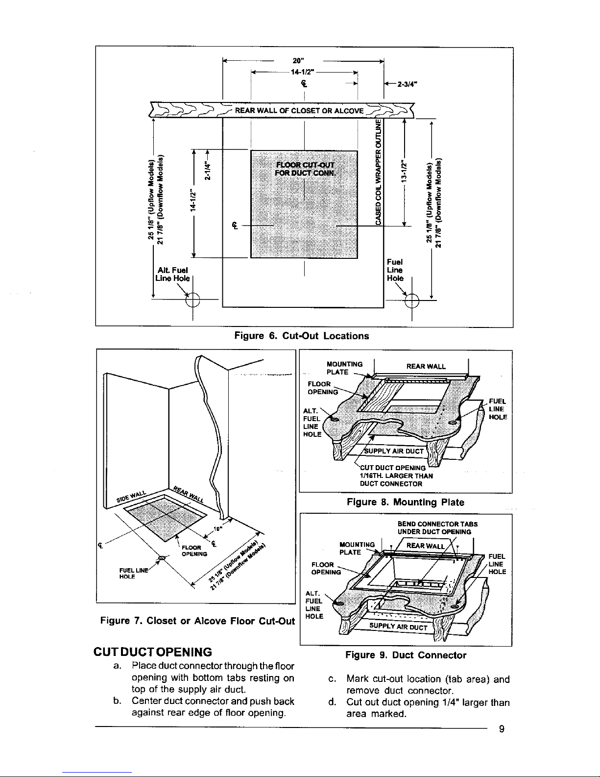
Figure 6. Cut-Out Locations
HOLE
Figure 7. Closet or Alcove Floor Cut-Out
MOUNTING
PLATE
REAR WALL
f
FUEL
1/16TH. LARGER THAN
DUCT CONNECTOR
Figure 8, Mounting Plate
BEND CONNECTOR TABS
UNDER DUCT OPENING
MOUNTING
PLATE
FLOOR
CUTDUCTOPENING
a. Place duct connectorthroughthe floor
b.
Figure 9. Duct Connector
opening with bottom tabs resting on
top of the supply air duct.
Center duct connector and push back
against rear edge of floor opening.
c. Mark cut-out location (tab area) and
remove duct connector.
d. Cut out duct opening 1/4" larger than
area marked.
9

TABS TABS
-- DUCT _ DUCT
1. INSERT DUCT PLENUM CONNECTOR
INTO DUCT CUT-OUT.
2. BEND Bo'n'OM TABS OVER
AND ONTO THE UNDERNEATH
DUCTSER_CE.
Figure 10. Installation of Duct Connector
INSTALL FURNACE MOUNTING PLATE
a. Bend tabs on furnace mounting plate
upwards 90°
b. Place mounting plate (supplied within
duct connector) at rear of the floor
opening (See Figure 8).
INSTALL DUCT CONNECTOR
e. Place duct connector through the floor
opening with bottom tabs extending
through the duct opening. (See Figure 9)
b. Secure duct connector to floor.
c. Bend bottom tabs under and up tightly
against the supply air duct (See Figure
10).
NOTE: The duct connector is designed for
use on ducts 12" in width. When using the
connector on 12" wide ducts, there may be
insufficient clearance to bend the tabs on two
sides of the duct connector. In such cases the
tabs may be attached to the sides of the duct
by using sheet metal screws or other suitable
fasteners. (See Figure 11).
if ial_e is used to provide a better seal, it should
be approved by applicable national orlocal codes.
ALTERNATE ATTACHMENT METHODS
This procedure may also be used to install a
furnace duct connector to narrow metal
ductworkwhere insufficientclearance prevents
bending of the duct connector tabs at the
side(s) of the duct. (See Figure 12).
1. Score and cut the topof the metal duct as
indicated in Step 1 or Step 2. With Step 1
choice, also cut out the metal from the
shaded area "A".
2. Fold the duct flap "B" up, (See Step 3).
3. At the front-to-back of duct run (Area
"A"), bend the duct tabs and secure them
directly to the duct.
DuctConnector "--_
I
Duct
f Na_ow
Figure 11. Narrow Duct Installation
Duct
STEP 1. STEP 2,
Fold Back Flap "B" Cut Fold _ Rap'B"
"' _a "O_A" "B" I
_ Fold Back Rap "B. _-- Fold Back Flap'B"
Bend DUCt Connector Tabs Up
and Over-(alonglengthof duct)
Stapk_ Folded Duct
Flap (lypl _0,_ide of Du_
Connector
Duct
STEP 3. S1]EP 4.
Figure 12. Alternate Installation
10
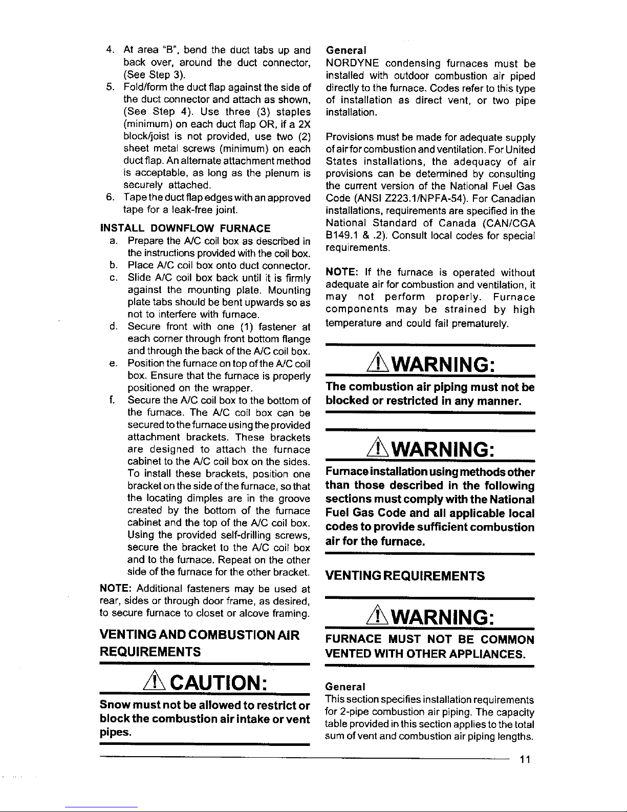
4. At area"B",bendtheducttabsupand
backover,aroundtheductconnector,
(SeeStep3).
5. Fold/formtheductflapagainstthesideof
theductconnectorand attach as shown,
(See Step 4). Use three (3) staples
(minimum) on each duct flap OR, if a 2X
block/joist is not provided, use two (2)
sheet metal screws (minimum) on each
duct flap. An alternate attachment method
is acceptable, as long as the plenum is
securely attached.
6. Tape the duct flap edges with anapproved
tape for a leak-free joint.
INSTALL DOWNFLOW FURNACE
a. Prepare the NC coil box as described in
the instructionsprovidedwith the coil box.
b. Place A/C coil box onto duct connector.
c. Slide A/C coil box back until it is firmly
against the mounting plate. Mounting
plate tabs should be bent upwards so as
not to interfere with furnace.
d. Secure front with one (1) fastener at
each corner through front bottom flange
and through the back of the A/C coilbox.
e. Positionthe furnace ontop ofthe A/C coil
box. Ensure that the furnace is properly
positioned on the wrapper.
f. Secure the A/C coil box to the bottom of
the furnace. The A/C coil box can be
secured to the furnace using the provided
attachment brackets. These brackets
are designed to attach the furnace
cabinet to the AJC coil box on the sides.
To install these brackets, position one
bracket on the side of the furnace, so that
the locating dimples are in the groove
created by the bottom of the furnace
cabinet and the top of the A/C coil box.
Using the provided self-drilling screws,
secure the bracket to the A/C coil box
and to the furnace. Repeat on the other
side of the furnace for the other bracket.
NOTE: Additional fasteners may be used at
rear, sides or through door frame, as desired,
to secure furnace to closet or alcove framing.
VENTING AND COMBUSTION AIR
REQUIREMENTS
CAUTION:
Snow must not be allowed to restrict or
block the combustion air intake or vent
pipes.
General
NORDYNE condensing furnaces must be
installed with outdoor combustion air piped
directly to the furnace, Codes refer to thistype
of installation as direct vent, or two pipe
installation.
Provisions must be made for adequate supply
of air for combustion and ventilation. For United
States installations, the adequacy of air
provisions can be determined by consulting
the current version of the National Fuel Gas
Code (ANSI Z223.1/NPFA-54). For Canadian
installations, requirements are specified in the
National Standard of Canada (CAN/CGA
B149.1 & .2). Consult local codes for special
requirements.
NOTE: If the furnace is operated without
adequate air for combustion and ventilation, it
may not perform properly. Furnace
components may be strained by high
temperature and could fail prematurely.
WARNING:
The combustion air piping must not be
blocked or restricted in any manner,
z WARNING:
Fumace installation using methods other
than those described in the following
sections must comply with the National
Fuel Gas Code and all applicable local
codes to provide sufficient combustion
air for the fumace,
VENTING REQUIREMENTS
/t',WARNING:
FURNACE MUST NOT BE COMMON
VENTED WITH OTHER APPLIANCES.
General
This section specifies installation requirements
for 2-pipe combustion air piping. The capacity
table provided in this section applies to the total
sum of vent and combustion air piping lengths.
11
 Loading...