

Page 1
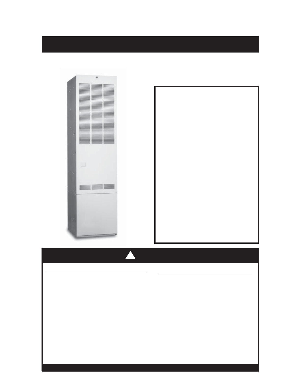
Downfl ow, Direct Vent (Sealed Combustion)
Forced Air Gas & Oil Furnaces
Installation Instructions
Series M1B, M1G, M1M & M5S
For installation in:
• Manufactured Homes
• Recreational Vehicles, Park Models, &
Manufactured Buildings
• Modular Homes/Buildings
ATTENTION INSTALLERS:
It is your responsi b il i ty to k no w th i s pro du ct
better than your customer. This includes
being able to install the product according
to strict safety guidelines and instructing the
customer on how to operate and maintain the
equipment for the life of the product. Safety
should always be the deciding factor when
installing this product and using common
sense plays an important role as well. Pay
attenti on to all safety warni ngs and any other
special notes highlighted in the manual.
Improper installation of the furnace or failure
to follow safety warnings could result in
serious injury, death, or property damage.
These instructions are primarily intended
to assist qualifi ed individuals experienced
in the proper installation of this appliance.
Some local codes require licensed
installation/service personnel for this type
of equipment. Please read all instructions
carefully before starting the installation.
Return these instructions to the customer’s
package for future reference.
!
WARNING:
WHAT TO DO IF YOU SMELL GAS
• Do not try to light any appliance.
• Do not touch any electrical switch;
do not use any phone in your
building.
• Leave the building immediately.
• Immediately call your gas supplier
FIRE OR EXPLOSION HAZARD
• Failure to follow safety warnings
exactly could result in serious
injury or property damage.
• Installation and service must
be performed by a qualified
installer, service agency or the
gas supplier.
from a neighbors phone. Follow
the gas suppliers instructions.
• If you cannot reach your gas
supplier, call the fi re department
DO NOT DESTROY. PLEASE READ CAREFULLY AND KEEP IN A SAFE PLACE FOR FUTURE REFERENCE.
• Do not store or use gasoline
or other fl ammable vapors and
liquids in the vicinity of this or
any other appliance.
Page 2

SAFETY INFORMATION .............................. 3
REQUIREMENTS & CODES ........................ 3
GENERAL INFORMATION ........................... 5
Warranty Information ................................ 5
Minimum Clearances ............................... 5
Applications ............................................. 6
Unit Location ............................................ 6
CIRCULATING AIR REQUIREMENTS ......... 7
Return Air Connections ........................... 7
Supply Air Connections ............................ 7
Operating Instructions - Oil Gun ..............22
Operating Instructions - Gas Gun ............22
How to Shut Off Gas - Gas Gun ...........22
Burner Adjustments .................................22
Gas Pressure .......................................22
Pilot Flame ...........................................22
Combustion Air ........................................23
Gas Gun ...............................................23
Oil Gun .................................................23
Electrode Setting - Oil Gun ......................23
Switching Honeywell (R7184) Ignition from
Interrupted to Intermittent ........................23
FURNACE INSTALLATION .......................... 8
General Information .................................. 8
Requirements & Codes ............................ 8
Locating & Cutting Duct Openings .......... 8
Standard Duct Connector Installation ....... 9
Alternate Attachment Method ...............10
Round Duct Connector Installation ..........10
Installing the Furnace ..............................10
ROOF JACK INSTALLATION ......................11
Roof Jack Selection .................................11
Application Notes .....................................11
Locating & Cutting Roof Openings ..........12
Installing the Roof Jack ............................13
Installation of Transit-Mode Vent System .13
Manufactured Home Factory.................13
ELECTRICAL INFORMATION .....................14
Line Voltage Wiring ..................................14
Connecting Power Supply Wires ...........15
Low Voltage Wiring ..................................15
Connecting Thermostat Wires ...............15
Verifying Anticipator Setting ..................15
Grounding ................................................15
FUEL SUPPLY AND PIPING .......................16
Oil Tank & Piping Istallation .....................17
One Line System ..................................17
Two Line System ...................................17
Fuel Line Hook Up ..................................17
Leak Check .............................................18
Priming Honeywell R7184 ......................18
Priming Beckett 7505 ..............................18
Fuel Oil Type ...........................................18
Conversion to Propane Gas ...................18
Atmospheric & Direct Ignition ..............18
High Altitude Conversion ........................19
Flue Gas Sampling .................................19
STARTUP & ADJUSTMENTS .....................20
Lighting Instructions - Pilot Models ..........20
How to Shut Off Gas - Pilot Models ......21
Operating Instructions - Direct Ignition ...21
How to Shut Off Gas - Direct Ignition ...22
OPERATING SEQUENCE ...........................24
Standing Pilot ..........................................24
Standing Pilot w/ Induced Draft Blower ...24
M1 Models - Direct Ignition ......................24
Oil Gun Models ........................................24
Gas Gun Models ......................................24
FURNACE CONTROLS & FUNCTIONS .....25
Furnace On-Off Switch ............................25
Limit Control ............................................25
Gas Valve.................................................25
Roll Out Switch - M1G .............................25
Oil Burner Primary Control ......................25
Summer Cooling - B,C,D Series ..............25
TROUBLESHOOTING .................................26
Standing Pilot Models ..............................26
Direct Ignition Models ..............................26
Oil Gun Models ........................................27
OPTIONAL ACCESSORIES ........................28
MAINTENANCE ...........................................30
Homeowner Information ..........................30
Installer Information Information ..............30
FIGURE & TABLES ......................................31
Table 10 - Furnace Specifi cations ........31
Table 11 - Orifi ce Sizes - High Alt. ........32
Table 12 - Blower Speed Selection .......32
Gas Information .......................................33
Table 13 - Gas Flow Rates ...................33
Table 14 - Gas Pipe Capacities ............33
Wiring Diagrams ......................................34
Fig. 39 - Gas Furnace - 056, 070 .........34
Fig. 41 - Standing Pilot - 077, 090 ........35
Fig. 42 - Gas Furn. w/ac 056, 070 ........36
Fig. 43 - Standing Pilot. w/ac 077, 090 .37
Fig. 44 - Gas Only (M1M Models) ........38
Fig. 45 - Gas & Oil (M1B & M5S) .........39
Installation Checklist ................................40
2
Page 3
SAFETY INFORMATION
Safety markings are used frequently throughout
this manual to designate a degree or level
of seriousness and should not be ignored.
WARNING indicates a potentially hazardous
situation that if not avoided, could result in
personal injury or death. CAUTION indicates
a potentially hazardous situation that if not
avoided, may result in minor or moderate injury
or property damage.
WARNING:
WARNING:
Do not use this appliance if any
part has been submerged under
water. Immediately call a qualifi ed
service technician to inspect the
appliance and to replace any part
of the control system and any gas
control that has been submerged
underwater.
The safety information listed
below must be followed during the
installation, service, and operation
of this furnace. Failure to follow
safety recommendations could
result in possible damage to the
equipment, serious per
or death
• Use only with type of gas approved for this
furnace. Refer to the furnace rating plate.
• Install this furnace in accordance to the
minimum clearances to combustible materials
listed in Table 1 (page 5).
• Provide adequate combustion air to the furnace
space as specifi ed on page 23.
• Combustion products must be discharged
outdoors. Connect this furnace to an approved
vent system, as specifi ed on pages 13 - 14.
• Never test for gas leaks with an open fl ame.
Use a commercially available soap solution to
check all connections (page 18).
• This furnace is designed to operate with a
maximum external pressure rise of 0.5 inches
of water column. Consult Table 8 (page 38),
and the rating plate for the proper circulating
air fl ow and temperature rise.
NOTE: It is important that the duct system be
designed to handle the desired fl ow rate and
external pressure rise. An improper ly designed
duct system can result in nuisance shutdowns,
and comfort or noise issues.
• This furnace may not be used for temporary
heating of buildings or structures under
construction.
• When supply ducts carry air circulated by the
furnace to areas outside the space containing
the furnace, the return air shall also be handled
by duct(s) sealed to the furnace casing and
terminating outside the space containing the
furnace. See page 14.
.
sonal injury
Notice to Installer
Installer is advised to carefully follow all
instructions and warnings in this manual to insure
maximum performance, safety, and operating
efficiency of these appliances. Improper
installation may create hazardous conditions,
and will void the appliance warranty.
WARNING:
PROPOSITION 65 WARNING:
This product contains chemicals
known to the state of California
to cause cancer, birth defects or
other reproductive harm.
REQUIREMENTS AND CODES
This furnace must be installed in accordance with
these instructions, all applicable local building
codes and the current revision of the National
Fuel Gas Code (NFPA54/ANSI Z223.1) or the
Natural Gas and Propane Installation Code,
CAN/CGA B149.1.
CE générateur d’air chaud doit être installé
conformément aux instructions du fabricant
et aux codes locaux. En l’absence de code
local, respecter la norme ANSI Z223.,1,
institulé National Fuel Gas Code ou les codes
d’installation CAN/GCA-B149.
The Commonwealth of Massachusetts requires
compliance with regulation 248 CMR 4.00 and
5.00 for installation of through – the – wall vented
gas appliances as follows:
1. For direct-vent appliances, mechanicalvent heating appliances or domestic hot
water equipment, where the bottom of the
vent terminal and the air intake is installed
below four feet above grade the following
requirements must be satisfi ed:
3
Page 4

a.) A carbon monoxide (CO) detector and
alarm shall be placed on each fl oor
level where there are bedrooms. The
detector shall comply with NFPA 720
(2005 Edition) and be mounted in the
living area outside the bedroom(s).
b.) A (CO) detector shall be located in
the room that houses the appliance or
equipment and shall:
• Be powered by the same electrical
circuit as the appliance or equipment.
Only one service switch shall power
the appliance and the (CO) detector;
• Have battery back-up power;
• Meet ANSI/UL 2034 Standards
and comply with NFPA 720 (2005
Edition); and Approved and listed
by a Nationally Recognized Testing
Laboratory as recognized under 527
CMR.
c.) A Product-approved vent terminal must
be used, and if applicable, a productapproved air intake must be used.
Installation shall be in strict compliance
with the manufacturer’s instructions. A
copy of the installation instructions shall
remain with the appliance or equipment
at the completion of the installation.
d.) A metal or plastic identifi cation plate shall
be mounted at the exterior of the building,
4 feet directly above the location of vent
terminal. The plate shall be of suffi cient
size, easily read from a distance of eight
feet away, and read “Gas Vent Directly
Below”.
2. For direct-vent appliances, mechanical
vent heating appliances or domestic hot
water equipment where the bottom of the
vent terminal and the air intake is installed
above four feet above grade the following
requirements must be satisfi ed:
a.) A (CO) detector and alarm shall be
placed on each fl oor level where there
are bedrooms. The detector shall comply
with NFPA 720 (2005 Edition) and be
mounted in the living area outside the
bedroom(s).
b.) The (CO) detector shall:
• Be located in the room that houses
the appliance or equipment;
• Be hard-wired, batter y powered or both.
• Shall comply with NFPA 720 (2005
Edition).
c.) A product-approved vent terminal must
be used, and if applicable, a productapproved air intake must be used.
Installation shall be in strict compliance
with the manufacturer’s instructions. A
copy of the installation instructions shall
remain with the appliance or equipment
at the completion of the installation.
The information listed below is for reference
purposes only and does not necessarily have
jurisdiction over local or state codes. Always
consult with local authorities before installing
any gas appliance.
Combustion and Ventilation Air
• US: National Fuel Gas Code (NFGC), Air for
Combustion and Ventilation
• CANADA: Natural Gas and Propane Installation Codes (NSCNGPIC), Venting Systems
and Air Supply for Appliances
Duct Systems
• US and CANADA: Air Conditioning Contractors
Association (ACCA) Manual D, Sheet Metal
and Air Conditioning Contractors National
Association (SMACNA), or American Society
of Heating, Refrigeration, and Air Conditioning
Engineers (ASHRAE) Fundamentals Handbook
Electrical Connections
• US: National Electrical Code (NEC) ANSI/
NFPA 70
• CANADA: Canadian Electrical Code CSA
C22.1
Gas Piping and Gas Pipe Pressure Testing
• US: NFGC and National Plumbing Codes
• CANADA: NSCNGPIC
General Installation
• US: Current edition of the NFGC and the
NFPA 90B. For copies, contact the National
Fire Protection Association Inc., Batterymarch
Park, Quincy, MA 02269; or American Gas
Association, 400 N. Capitol, N.W., Washington
DC 20001 or www.NFPA.org
• CANADA: NSCNGPIC. For a copy, contact
Standard Sales, CSA International, 178
Rexdale Boulevard, Etobicoke (Toronto),
Ontario, M9W 1R3 Canada
Safety
• US: (NFGC) NFPA 54–1999/ANSI Z223.1 and
the Installation Standards, Warm Air Heating
and Air Conditioning Systems ANSI/NFPA 90B.
• Federal Manufactured Home Constructions
& Safety Standard (H.U.D. Title 24, Part
3280.707[a][2])
• The Standard for Manufactured Home
Installations (Manufactured Home Sites,
Communities, and Set-Ups) ANSI A225.1 and/
or CAN/CSA-2240 MH Series).
4
Page 5
• American National Standard (ANSI-119.2/
NFPA-501C) for all recreational vehicle
installations.
• CANADA: CAN/CGA-B149.1 and .2–M00
National Standard of Canada. (NSCNGPIC)
GENERAL INFORMATION
Manufacturer Warranty - Owner’s
Responsibilities
It is the sole responsibility of the homeowner to
make certain the gas furnace has been correctly
set up and converted to the proper fuel (L.P. gas
or Natural gas) and adjusted to operate properly.
All gas furnaces are manufactured for Natural gas
and must be fi eld converted when using L.P. gas.
CAUTION:
• Do Not alter or modify this furnace
or any of its components.
• Never attempt to repair damaged
or inoperable components. This
may cause unsafe operation, explosion, fi re and/or asphyxiation.
• If furnace malfunctions or does
not operate properly, contact a
qualifi ed service agency or gas
utility for assistance.
A warranty certifi cate with full details is included
with these instructions. However, NORDYNE
will not be responsible for any costs found
necessary to correct problems due to improper
setup, improper installation, furnace adjustments,
improper operating procedure on the part of the
user, etc. Carefully review these responsibilities
with your manufactured housing dealer, service
company or gas supplier. Some specifi c examples
of service calls which cannot be included in
warranty payments are:
• Converting the furnace to use another type of
gas.
• Repairing duct work in the home found to be
faulty.
• Correcting wiring problems in the electrical
circuit supplying the furnace.
• Resetting circuit breakers, blown fuses or other
switches.
• Correcting problems due to improper gas
supply pressure to the furnace.
• Providing instructional training on how to light
and operate the furnace.
• Furnace problems caused by installation of an
air conditioner, heat pump or other air comfort
devices.
• Adding a Roof Jack extension because of
unusual wind and/or snow conditions.
• Revising installation of the furnace flue
assembly (Roof Jack).
• Adjusting or calibrating of thermostat.
• Any construction debris which falls into fl ue
system.
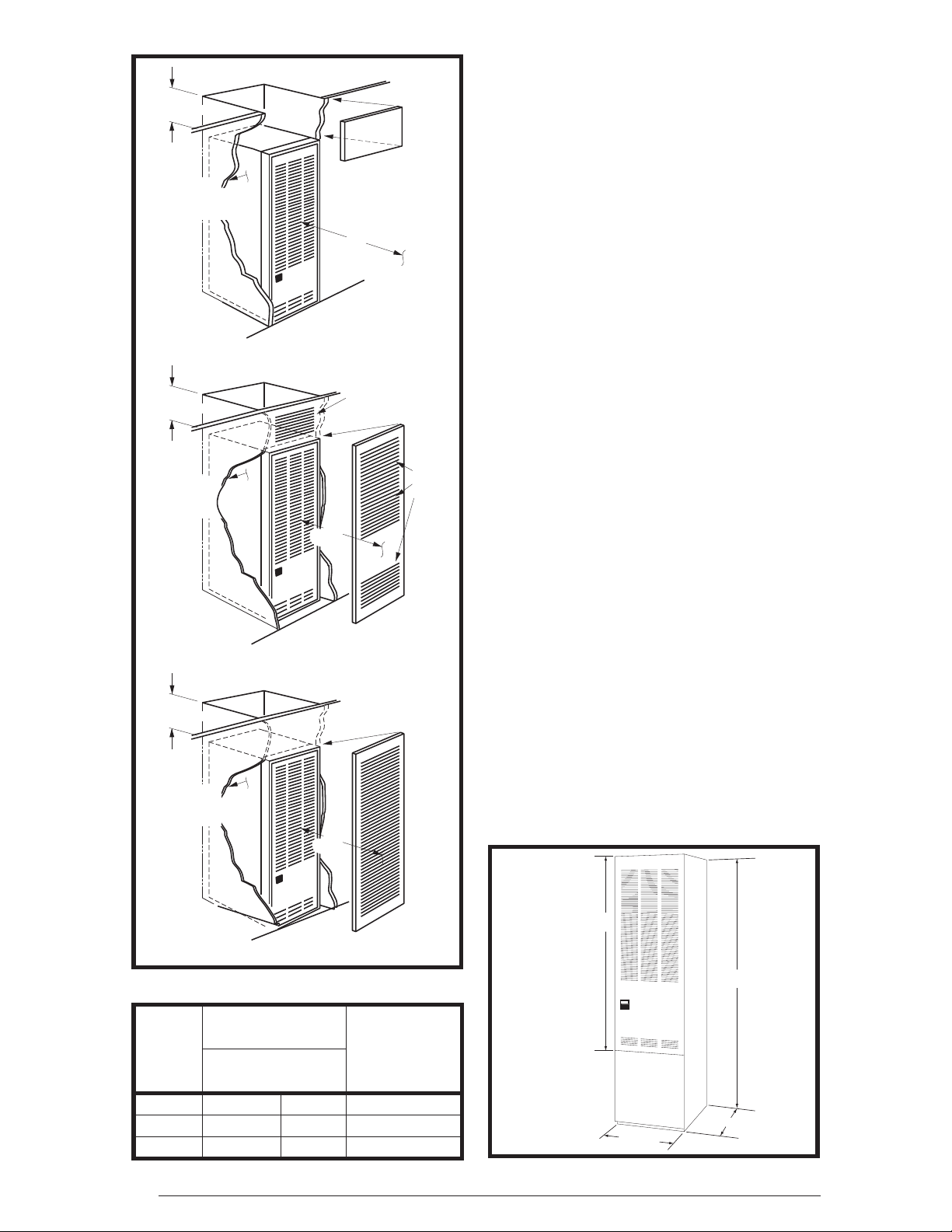
Minimum Clearances
This heating appliance must be installed with
clearances not less than the minimums listed
in Table 1. This furnace must be installed with
ample clearance for easy access to the air fi lter,
blower assembly, bur ner assembly, controls, and
vent connections. See Figures 1 - 3 (page 6).
• The dimensions of the room or alcove must be
able to accommodate the overall size of the
furnace and the installation clearances listed
in Table 1 and in Figure 4 (page 6).
• Alcove installations: minimum 18” clearance
at front of furnace shall be provided for future
servicing. A removable access panel should
be installed between top of the furnace door
frame and the ceiling.
• Closet installations must use a louvered door
having a minimum free area of 235 sq. in. when
located 6” from furnace or 390 sq. in. for 5 ton
ready M1/M5 furnaces. For special clearance
between 1” and 6”, requirements are a louvered
door with a minimum of 250 sq. in. free area,
with the openings in the closet door in line with
the louvered openings in the furnace door. A
fully louvered closet door may be used. See
Circulating Air Requirements (page 7).
ALL MODELS CLOSET ALCOVE
Front 6” 18”
Back 0” 0”
Sides 0” 0”
Roof Jack 0” 0”
To p 6 ” 6 ”
Top and Sides of Duct 0” 0”
Bottom of Duct
B Cabinet 0” 0”
A Cabinet
(w/ coil box)
A Cabinet
(w/o coil box)
Table 1. Minimum Clearances
0” 0”
1/4” 1/4”
5
Page 6
6" (152 mm)
Top Clearance
0" Side
Clearance
to Furnace
Cabinet
6" (152 mm)
Top Clearance
0" Side
Clearance
to Furnace
Cabinet
6" (152 mm)
Top Clearance
0" Side
Clearance
to Furnace
Cabinet
Removable access
panel should be
installed above
furnace door frame
to access roof jack
18"
(457 mm)
Figure 1. Alcove Installation
Provide min. 235
sq. in. (1516 cm )
open free area in
front or side wall
6"
(152 mm)
CLOSET DOOR
Figure 2. Closet Installation
Provide min. 250
sq. in. (1613 cm )
open free area in
front or side wall
1"
(25 mm)
Nearest
Wall or
Partition
2
or
In closet
door
located
at top,
center
or bottom
2
or
in closet
door
a fully
louvered
door may
be used
Applications
M1 Series gas and M5 Series oil furnaces are
listed direct vent (sealed combustion), downfl ow
heating appliances for manufactured (mobile)
homes, recreational vehicles, and for use in
residential/modular/commercial construction.
The furnace must be located so that venting can
be properly achieved.
Air conditioning may be added to structures with
M1/M5 series furnaces using air conditioning or
conventional units. This Installation Instruction
manual includes special requirements for
incorporation of air conditioning equipment to the
M1/M5 series of furnaces. See Tabel 12 (page 32).
Multi-speed blower assemblies shown in Table
2, have been certifi ed for fi eld installation in M1/
M5 Series furnaces.
Unit Location
• The furnace shall be appropriately located to
the supply and return air distribution system
(See Page 7). Sides and back of the furnace
may be enclosed by wall framing. See Minimum
Clearances (page 2) and Figures 1- 3.
• The furnace installation is only intended for
free air return through the furnace door louvers.
DO NOT connect a ducted return air system
directly to the furnace. Improper installation
may create a hazard and damage equipment,
as well as void all warranties.
• Furnace may be installed on combustible
flooring when using NORDYNE Duct
Connectors. See pages 9 & 10.
• When installed in a residential garage, the
furnace must be positioned so the burners and
the source of the ignition are located no less
than 18 inches above the fl oor and protected
from physical damage by vehicles.
CLOSET DOOR
Figure 3. Special 1” Clearance
Blower / Motor
Part
No.
Assembly
Blower
Wheel
Motor
(Hp)
A/C Capacity
(Tons)
903773 10 x 8 1/4 2, 2½ & 3
903413 11 x 8 1/2 2, 2½, 3 & 4
903890 11 x 8 3/4 2, 2½, 3, 4 & 5
Table 2. Blower Assemblies
6
“A”- 56"
“A” Model
w/o Coil
Cabinet
“B” Model
w/Coil
Cabinet
“B”- 76"
23 3/4"
19 3/4"
Figure 4. Overall Dimensions
Page 7
CIRCULATING AIR REQUIREMENTS
WARNING:
Do not allow combustion products
to enter the circulating air supply.
Failure to prevent the circulation
of combustion products into the
living space can create potentially
hazardous conditions including
carbon monoxide poisoning that
could result in personal injury or
death.
All return ductwork must be secured
to the furnace with sheet metal screws.
For installations in confi ned spaces,
all return ductwork must be adequately
sealed. The joint between the furnace
and the return air plenum must be
air tight.
The surface that the furnace is
mounted on must provide sound
physical support of the furnace with
no gaps, cracks or sagging between
the furnace and the fl oor or platform.
Return air and circulating air ductwork
must not be connected to any other
heat producing device such as a
fireplace insert, stove, etc. This
may result in fi re, explosion, carbon
monoxide poisoning, personal injury,
or property damage.
Return Air Connections
U.S.A. home manufacturers shall comply with
all of the following conditions to have acceptable
return air systems for closet installed forced air
heating appliances:
• The return air opening into the closet shall not
be less than specifi ed in the appliance’s listing.
• The cross-sectional area of the return duct
system leading into the closet, when located
in the fl oor or ceiling shall not be less than 235
square inches (or 390 square inches for 5 ton
ready M1/M5 Furnaces).
CAUTION:
HAZARD OF ASPHYXIATION: Do not
cover or restrict return air opening.
• Means shall be provided that prevent
inadvertent closure of fl at objects placed over
the return air opening located in the fl oor of the
closet (versus the vertical front or side wall).
• The total free area of openings in the fl oor or
ceiling registers serving the return air duct
system must be at least 235 sq. in. At least
one register should be located where it is not
likely to be covered by carpeting, boxes and
other objects.
• Materials located in the return duct system
must have a fl ame spread classifi cation of
200 or less. This includes a closet door if the
furnace is in a closet.
• Noncombustible pans having 1” upturned
fl anges are located beneath openings in a
fl oor duct system.
• Wiring materials located in the return duct
system shall conform to Articles 300-22 of the
National Electrical Code (ANSI C1/NFPA-70).
• Gas piping is not run in or through the return
duct system.
CAUTION:
HAZARD OF ASPHYXIATION:
Negative pressure inside the
closet, with closet door closed
and the furnace blower operating
on high speed, shall be no more
negative than minus 0.05 inch
water column.
• Test the negative pressure in the closet with
the air-circulating fan operating at high speed
and the closet closed. The negative pressure is
to be no more negative than minus 0.05 inch
water column.
• Air conditioning systems may require more
duct register and open louver area to obtain necessary airflow. Use NORDYNE’s
certiduct program to determine proper duct
size for A/C.
Supply Air Connections
For proper air distribution, the supply duct system
must be designed so that the static pressure
measured external to the furnace does not
exceed the listed static pressure rating shown
on the furnace rating plate.
7
Page 8
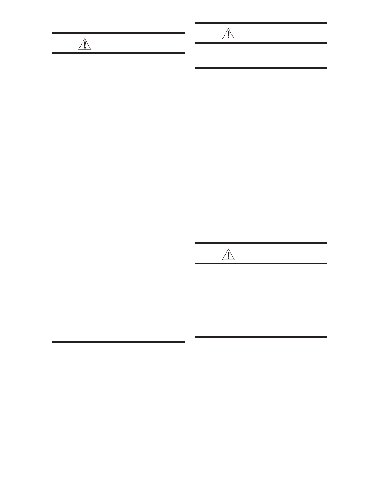
Location, size, and number of registers should
A Single trunk duct
B
Dual trunk duct
w/crossover connector
C
Transition duct
w/branches
be selected on the basis of best air distribution
and fl oor plan of the home. The supply air must
be delivered to the heated space by duct(s)
secured to the furnace casing, running full
size and without interruption.
• The M1 Series gas and M5 Series oil furnace
is certifi ed for use on wood fl ooring or supports,
but must be installed on top of a duct connector.
This factory supplied accessory must be
installed in the fl oor cavity and attached to the
supply air duct before the furnace is installed.
Three typical distribution systems are shown
in Figure 5. The location, size, and number of
registers should be selected on the basis of
best air distribution and fl oor plan of the home.
Figure 5. Typical Supply Duct System
FURNACE INSTALLATION
NOTE: These Installation procedures are
suggested for typical furnace installations.
Since all installations are different from each
other, the sequence of instructions may differ
from the actual installation. Only qualifi ed HVAC
technicians should install this furnace.
General Information
• The furnace must be leveled at installation and
attached to a properly installed duct system. Do
not use the back of the furnace for return
air. See page 7 for circulating requirements.
• The furnace must be installed so that all
electrical components are protected from
water.
• The dimensions of the room or alcove must be
able to accommodate the overall size of the
furnace and the installation clearances listed
in Table 1 and Figure 3 (page 6)
• The furnace must be installed upstream from
a refrigeration system.
• The plenum attached to the A/C coil box and
ductwork within 3 ft. of the furnace must be
installed so that surfaces are at least 1/4” from
combustible construction.
• The cabinet plug must always be used to close
the hole in the side of the furnace when rotating
the inducer.
M1/M5 models must be installed with the Nordyne
•
A/C coil box which are listed according to the
cabinet size of the furnace: “B” cabinet - 920169,
“C” cabinet - 920171, and “D” cabinet - 920172.
8
Requirements and Codes
Installer must be familiar with and comply with
all codes and regulations applicable to the
installation of these heating appliances and
related equipment. In the absence of local codes,
the installation must be in accordance with the
current provisions of one or more of the following
standards.
• Federal Manufactured Home Constructions
& Safety Standard (H.U.D. Title 24, Part
3280.707[a][2])
• American National Standard (ANSI-119.2/
NFPA-501C) for all recreational vehicle
installations.
• American National Standard (ANSI-Z223.1/
NFPA-54) and/or CAN/CSA B149 for all gasfi red furnace models.
• American National Standard (ANSI-Z95.1/
NFPA-31) and/or CSA B139 for all oil-fi red
furnace models.
• American National Standard (ANSI-C1/NFPA-
70) and/or CSA 22.1 Canadian Electric Code
Part 1 for all electrical fi eld wiring.
• Units have been researched under standards
UL 307A & B, UL727-1999, ANSI Z21.47b/
CSA 2.3b-2008, and CSA B140.10.
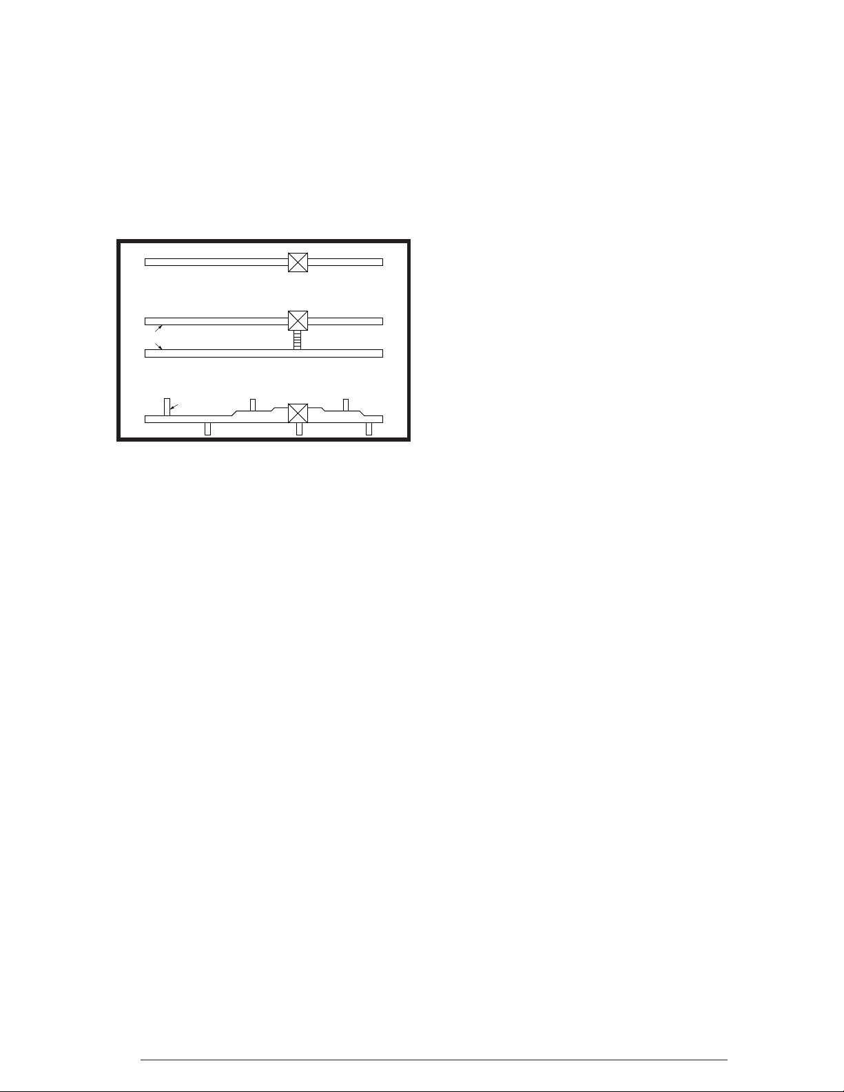
Locating and Cutting Duct Openings
Floor cut-outs and fuel line holes must be carefully
located to avoid misalignment of the furnace,
and vent piping. To locate standard ducts see
Figure 6 (page 9). For round ducts, see Figure 7.
1. Measure 10” from the rear wall or alcove and
mark the centerline of the cut-out on the fl oor.
2. Using the centerline as a starting point, draw
the rest of the duct cut-out to the dimensions
shown in Figures 6 or 7.
3. Cut out the fl oor opening 1/16” larger than
the actual cutout drawn. This will allow some
clearance when installing the duct connector.
4. Measure from the top of the fl oor down to the
top of the supply air duct to obtain the depth of
the fl oor cavity. NOTE: The depth of the fl oor
cavity shown as “X” in Figure 9 (page 9) will
determine the correct duct connector.
5. Determine which duct connector to use from
Table 3 (page 9).
Measure and drill gas hole. and cut out for cooling
6.
coil (if applicable). See Figures 6 or 7 (page 9).
Page 9
20"
14 1/2"
C
L
REAR WALL OF CLOSET OR ALCOVE
2 1/4"
FLOOR CUT-OUT
24"
21 3/4"
14 1/2"
23 1/4"
C
L
1 3/4"
3/4"
1 7/8"
FOR STANDARD
DUCT CONNECTORS
FURNACE OUTLINE
C
C
L
L
2 7/8"
CUT-OUT FOR
OPTIONAL
COOLING COIL
ALT FUEL-LINE
ENTRY 1 1/4" Dia.
1 3/4"
C
L
FURNACE
OUTER
DOOR
Figure 6. Cut-Out Dimensions for
Standard Duct Connectors
2 3/4"
10"
C
L
3/4"
FUEL
LINE
“X”
FLOOR
CAVITY
FLOOR OPENING
SUPPLY AIR DUCT
Figure 9. Floor Cavity
If Floor Cavity
“X” is:
7/8” / (22) 901987A 904008
C
L
2"
2” / (51) 901988A 904009
4-1/4” / (108) 901989A 904010
6-1/4” / (159) 901990A 904011
8-1/4” / (210) 901991A 904012
10-1/4” / (260) 901992A 904013
12-1/4” / (311) 901993A 904014
Note: Dimensions shown as Inches / (Millimeter)
Duct Connector
Type & Part Number
Standard Duct Round Duct
Table 3. Duct Connector Sizes
20"
C
L
10"
REAR WALL OF CLOSET OR ALCOVE
FLOOR
CUT-OUT FOR
24"
C
L
23 1/4"
21 3/4"
1 3/4"
3/4"
1 7/8"
2 7/8"
ROUND DUCT
(14 1/4” DIAMETER)
FURNACE OUTLINE
CUT-OUT FOR
C
C
L
L
COOLING COIL
ALT FUEL-LINE
ENTRY 1 1/4" Dia.
OPTIONAL
C
L
FURNACE
C
L
OUTER
DOOR
1 3/4"
Figure 7. Cut-Out Dimensions for
Round Duct Connectors
Hole for
Gas Line
Duct
Connector
Wood Floor
Connector
Tabs
Supply
Air Duct
Mounting Plate
10"
C
L
3/4"
FUEL
2"
LINE
Bend tabs
up 90°
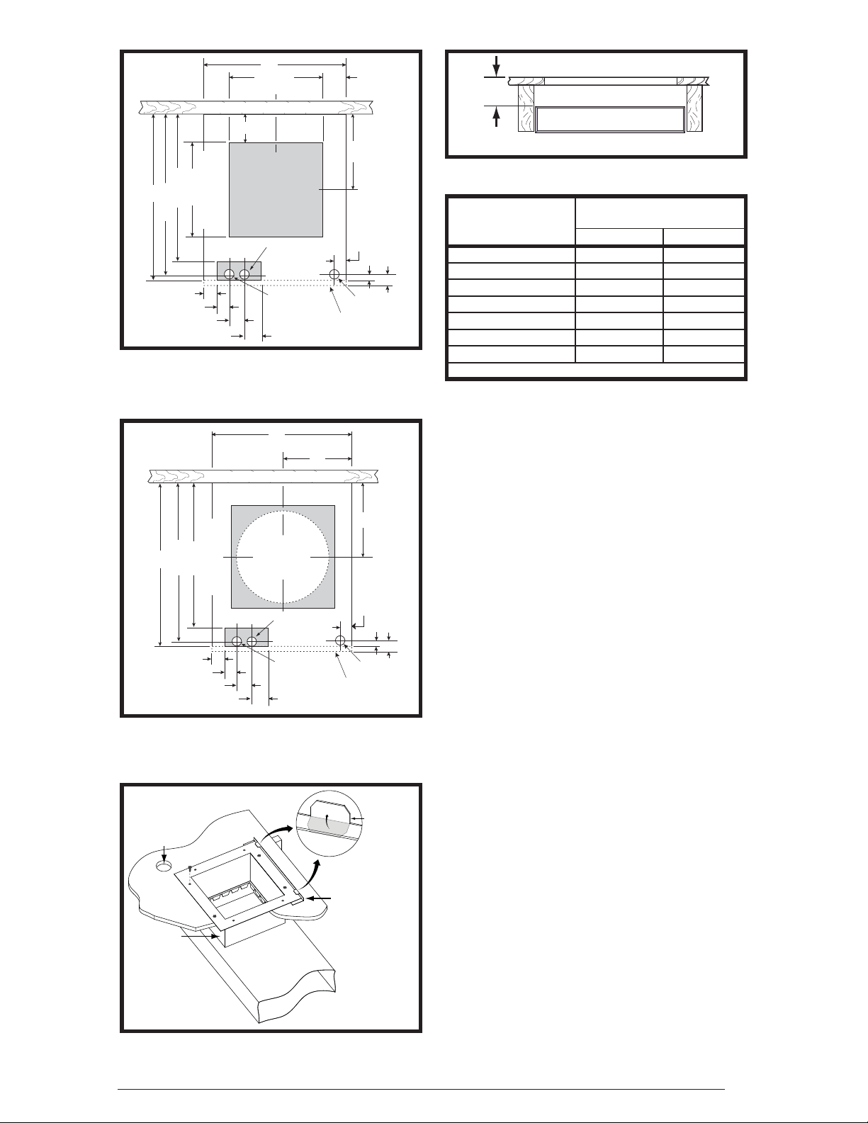
Standard Duct Connector Installation
The standard duct connector is designed for use
on ducts 12” in width. However ducts narrower
than 12” may not allow suffi cient clearances
for this type of installation. For an alternate
installation method, see page 10.
1. Center the duct connector in the fl oor opening
with bottom tabs resting on top of the supply
air duct.
Mark the cut-out area on the supply air duct by
2.
tracing around the connector tabs (Figure 8) of the
duct connector.
3. Remove the duct connector and cut out the
marked area of the supply air duct 1/4” larger
the actual cutout drawn.
4. Install the duct connector back in the fl oor
opening with the bottom tabs extending into
the supply air duct.
5. Install the mounting plate (Figure 8) under
the back side of the duct connector. Align the
screw holes in both components.
6. Secure the duct connector and the mounting
plate to the wood fl oor with appropriate size
screws.
7. Bend the connector tabs on the bottom of
the duct connector upwards and as tight as
possible against the supply air duct.
8. Bend both tabs on the mounting plate up 90°.
See Figure 10, (page 10)
9. Seal all connections with industrial grade
sealing tape or liquid sealant.
Figure 8. Standard Duct Connector In-
stalled
NOTE: Requirements for sealing ductwork
vary from region to region. Consult with local
codes for requirements specifi c to your area.
9
Page 10
DUCT CONNECTOR
SUPPLY
AIR DUCT
Duct connector tabs
Narrow
Duct
Duct
Flap
Staples or sheet metal screws
Narrow
Duct
BEND TABS TIGHTLY
AGAINST SUPPLY AIR DUCT
Figure 10. Duct Connector Tabs
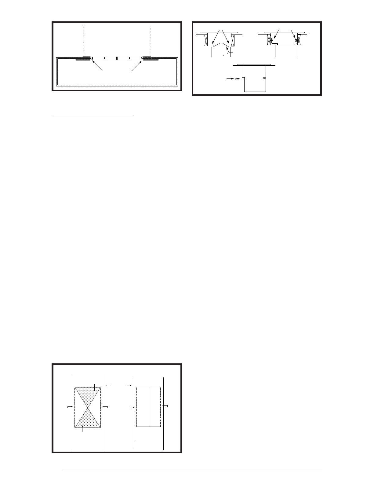
Alternate Attachment Method
The standard duct connector is designed for
use on ducts 12” in width. However if there is
insuffi cient clearance to bend the duct connector
tabs, this alternate attachment method may be
used.
1. Score and cut the top of the supply air duct as
indicated in Option 1 or Option 2 (Figure 11).
With Option 1 choice, cut out the metal from
the shaded area.
2. Fold the two fl aps (Options 1 or 2) up to form
the opening for the duct connector.
3. Install the duct connector with the bottom tabs
extending into the supply air duct.
4. Bend the tabs on the bottom of the duct
connector upwards and as tight as possible
against the supply air duct (Figure 12).
5. Form the fl aps (Options 1 or 2) up against the
duct connector as tight as possible.
6. Secure the duct connector fl aps to the supply air
duct with staples (3 minimum) or if a 2x block/
joist is not provided, use sheet metal screws
(2 minimum). NOTE: The duct connector tabs
may be attached to the air duct with sheet
metal screws or other suitable fasteners as
long as the duct connector and the air duct
are securely attached.
7. Seal all connections with industrial grade
sealing tape or liquid sealant.
NOTE: Requirements for sealing ductwork
vary from region to region. Consult with local
codes for requirements specifi c to your area.
Duct
Sheet metal
screws
Connector
Narrow
Duct
Figure 12. Narrow Ducts
Round Duct Connector Installation
1. Apply a bead of caulking, mastic, or other
approved sealant around bottom side of
connector.
2. Install and center the duct connector in the
fl oor opening.
3. Install the mounting plate under the back side
of the duct connector. See Figure 13 (page 11).
NOTE: Align the screw holes in both
components.
4. Secure the duct connector and the mounting
plate to the wood fl oor with appropriate size
screws.
5. Connect the round supply duct to the underside
of the duct connector and secure them with
fi eld supplied sheet metal screws.
6. Seal all connections with industrial grade
sealing tape or liquid sealant.
NOTE: Requirements for sealing ductwork
vary from region to region. Consult with local
codes for requirements specifi c to your area.
Installing The Furnace
Sides and back of the furnace may be enclosed
by wall framing such as in a closet or alcove. The
dimensions of the room or alcove must be able
to accommodate the overall size of the furnace
and the installation clearances outlined on page
2 and Figures 1 - 4 (page 6). The furnace shall
be appropriately connected to the supply and
return air distribution system as shown in Figures
14 & 15 (page 11).
OPTION 1 OPTION 2
Remove
this
Cut Here
Cut Here
Cut Here
Cut Here
Fold Flap Here
Remove
this
Flap
Flap
Cut Here
Cut Here
Supply
Air Duct
Fold Flap Here
Fold Flap Here
Figure 11. Narrow Air Duct Openings
10
Cut Here
Cut Here
Cut Here
Fold Flap Here
1. Remove furnace outer door(s) and bottom fuel
line knockout.
2. Place furnace onto duct connector and center
with fl oor opening.
3. Slide onto mounting plate. (Bottom rear slots
on furnace should engage with mounting plate
tabs.)
4. Secure front with one (1) fastener at each
corner (Figures 14 or 15).
NOTE: Additional fasteners may be used at rear,
sides or through door frame, as desired, to secure
furnace to closet or alcove framing.
Page 11
DUCT
CONNECTOR
SCREWS
MOUNTING
PLATE
ROOF JACK INSTALLATION
Required ceiling and roof cut-out openings (see
Figure 11) must be carefully located to avoid
misalignment of the furnace and Roof Jack.
Note: Install only Roof Jack Assemblies listed
in Table 4 on this heating appliance.
FUEL
LINE
HOLES
14” SUPPLY
CONNECTION
Figure 13. Round Duct Connector Installed
MTG. PLATE TABS
SECURE FURNACE
WITH 2 FASTENERS AT FRONT
CORNER HOLES
Knockout Over Holes
SUPPLY AIR DUCT
SLIDE FURNACE
ALL THE WAY BACK
ONTO MTG. PLATE
Figure 14. “A” & “B” Cabinet Furnaces
SLIDE FURNACE
BACK AGAINST
MTG. PLATE
MTG. PLATE TABS
SECURE FURNACE
WITH 2 FASTENERS
AT FRONT CORNER HOLES
FUEL LINE HOLES
SUPPLY
AIR DUCT
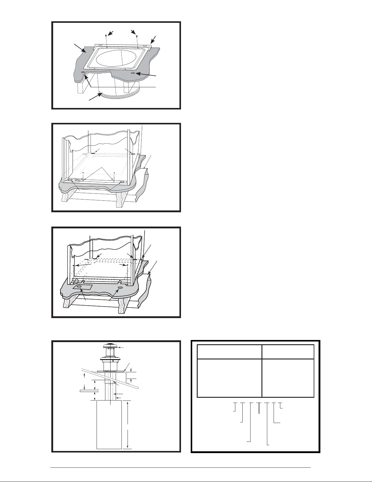
Roof Jack Selection
1. Determine depth of ceiling cavity from center
of roof opening to center of ceiling opening.
(See Dimension “A” in Figure 16.)
2. Determine ceiling height and subtract height
of furnace. (See Dimension “B” in Figure 16.)
3. Add dimensions A + B (and X from Table 5
and Figure 18 if slant deck fl ashing is used).
The total length of (A + B + X) must be within
the minimum and maximum range of one of
the Roof Jacks listed in Table 4.
Application Notes:
• FAW, FAWT, SAW and SAWT Series Roof
Jacks with a 5” diameter inner vent pipe may
be used with all models of M1 Series gas and
M5 Series oil furnaces.
F = Flat Flashing: fl exes from 0/12 to 1/12 roof
slope. See Figure 17 (page 12).
S = Slant Flashing: 2.5/12 Slope fl exes from
1/12 to 4/12 roof slope, 4/12 fl exes from
3/12 to 5/12. See Figure 18.
• Stainless steel roof jacks are available.
• M1/M5 furnaces may be used with roof jacks
as tall as 170” (except M1M 056 & M1B 066
models, which are limited to 120”). An internal
roof jack extension (p/n 901935 - 10”, p/n
903107 - 18”) can be used to increase roof
jack height. All connections inside the home
must be made below the ceiling.
Figure 15. “A” Cabinet Furnace on Coil
Cabinet
ROOF JACK
SLANT DECK
PITCHED
ROOF
CEILING
CAVITY
CEILING
“A”
“B”
Furnace
FLASHING
"X" (SEE TABLE 5)
Roof
Opening
Flue Pipe
Combustion Air Pipe
56" or 76"
Figure 16. Ceiling Cavity Depth
NOTE: If the roof jack crown is covered or blocked
with snow, the furnace will not operate properly.
MODEL NUMBER
(F,S)AW(T)1523-(0,2,4)(A,S) 15” - 23”
(F,S)AW(T)2135-(0,2,4)(A,S) 21” - 35”
(F,S)AW(T)2747-(0,2,4)(A,S) 27” - 47”
(F,S)AW(T)3563-(0,2,4)(A,S) 35” - 63”
(F,S)AW(T)5195-(0,2,4)(A,S) 51” - 95”
SSAW
F = FLAT FLASHING
S = SLANT FLASHING
AW= ALL WEATHER
TYPE:
BLANK = NON-TRANSIT
T= TRANSIT MODE
APPROX. LENGTH
BELOW FLASHING
47 - 2
T
27
MIN. ADJ.
LENGTH
MAX. ADJ.
LENGTH
FLUE STEEL TYPE
A= ALUMINIZED
S=STAINLESS
FLASHING
PITCH/12" RISE
0=FLAT
2=2.5/12
4=4/12
Table 4. Roof Jack Assemblies
11
Page 12
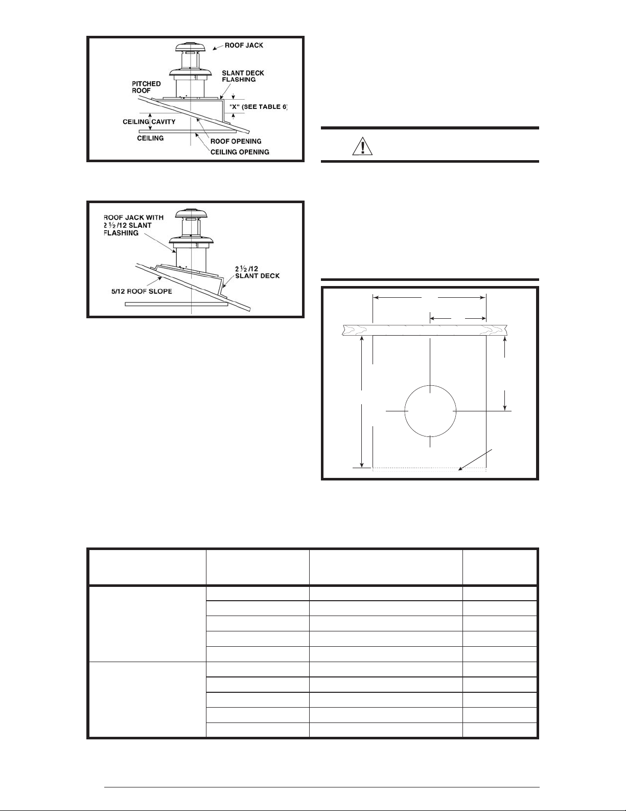
1. Locate center of Roof Jack opening, measure
CEILING
CUT-OUT FOR
FLUE AND
ROOF JACK
C
L
C
L
24"
20"
13 1/2"
REAR WALL OF CLOSET OR ALCOVE
10"
FURNACE
OUTER
DOOR
FURNACE OUTLINE
13 1/2” from the rear wall of closet or alcove
along the center line of furnace and fl oor
opening. See Figure 19.
2. Cut ceiling and roof holes as follows:
• Ceiling = 8 3/4” (222 mm) diameter
• Roof = 9 3/8” (238 mm) diameter
IMPORTANT:
Figure 17. Example of Flat Jack
with Flashing
Figure 18. Example of 2½/12 Slant Jack
with Flashing
If the home is located in regions where snow
accumulation exceeds 7” (HUD snowload zones)
use an external roof jack extension (p/n 901937).
Extensions are optional accessories and may be
purchased through your NORDYNE distributor.
Locating and Cutting Roof & Ceiling Openings
DO NOT ALLOW DEBRIS TO FALL INTO THE
FURNACE. THIS COULD CAUSE UNSAFE
OPERATION AND VOIDS THE FURNACE
WARRANTY. Use the top cap that comes with
the furnace packaging (or alternate protector) to
prevent debris from falling into the fur nace before
the fi nal roof jack connection is made
Refer to the installation
instructions provided with
optional air conditioning
packages when installing
furnaces with optional cooling
coil cabinet or with optional
C* series indoor coils.
Figure 19. Cut-Out Dimensions for
Flue & Roof Jack
12
ROOF JACK SERIES IF ROOF PITCH IS:
SLANT DECK
FLASHING NUMBER
“X” FACTOR
IS:
2” in 12” 903893 (2.5/12) 2-1/8”
2-1/2” in 12” 903893 (2.5/12) 2-1/2”
“F Series
3” in 12” 903894 (3/12) 2-7/8”
3-1/2” in 12” 903894 (3/12) 3-1/4”
4” in 12” 903895 (4/12) 3-5/8”
4-1/2” in 12” 903895 (2.5/12) 2-1/8”
5” in 12” 903895 (2.5/12) 2-1/2”
“S” Series (2.5 / 12
Pitch only)
Optional Deck Flashings for Flat and 2.5/12 Pitch Roof Jacks. 4/12 Pitch Roof Jacks not applicable.
5-1/2” in 12” 903894 (3/12) 2-7/8”
6” in 12” 903894 (3/12) 3-1/4”
6-1/2” in 12” 903895 (4/12) 3-5/8”
Table 5. Slant Deck Flashings
Page 13

Installing The Roof Jack
1. Apply caulking compound on underside of roof
fl ashing to form a continuous strip at least 3/8”
wide around the underside of the perimeter of
the fl ashing. See Figures 20 or 21.
2. Connect Roof Jack Assembly to the furnace.
Insert telescoping Roof Jack Assembly through
the opening cut on the roof.
3. Connect fl ue pipe to fl ue collar of furnace. See
Figure 22.
4. Connect combustion air pipe to furnace collar
with sheet metal screw (See Figure 22).
NOTE: It is recommended that the connection
of the combustion air pipe to the furnace be
made before the fl ashing is secured to the
roof to maintain alignment of roof jack and
furnace connections.
NOTE: For replacement furnaces, be sure
the inner fl ue pipe connects over the furnace
vent collar. DO NOT use a smaller diameter
inner fl ue pipe which could slide inside the
furnace vent collar and restrict the fl ow of
furnace fl ue products.
Secure roof jack with
appropriate fasteners
after connecting to
Caulk under roof
flashing to prevent
water leakage
Optional 2-piece ceiling
ring #902521
Secure lower roof
jack section with
no. 10 S.M. screws
Caulk under roof
ashing to prevent
water leakage
furnace
Figure 20. Flat Roof
Upper Roof Jack Section
Ceiling
Optional Slant
Deck Flashing
Secure ashing
with appropriate
fasteners
Roof
5. Attach Roof Flashing. If necessary, shift roof
fl ashing slightly in the roof opening so that
assembly is in alignment with furnace.
NOTE:
If fl ashing is mounted on 12 degree
angle, it may be necessary to adjust the angle
to match the roof pitch; (1/12 - 4/12 maximum).
6. Press down fi rmly on roof fl ashing (over
caulking) to make the seal with roof water tight.
7. Secure fl ashing with appropriate fasteners.
NOTE: For added protection against leaks, coat
the fl ashing plate and fasteners with approved
roofi ng compound.
Installation of Transit-Mode Venting System
Manufactured Home Factory
1. Furnace must be installed in accordance to
furnace installation manual.
2. Select appropriate Roof Jack from Table 4
(page 11).
3. Roof Jack (less upper Roof Jack crown), with
weather cap to be installed as described under
Install Roof Jack.
Ceiling
Figure 21. Pitched Roof
Figure 22. Combustion Air Pipe Connection
NOTE: Upper Roof Jack crown to be stored in
a prominent location inside manufactured home
until on-site installation.
13
Page 14

4. The four warning tags supplied must be
SCREWS
COMPLETED
ASSEMBLY
TO FURNACE
UPPER ROOF
JACK (CROWN)
INNER FLUE
PIPE
FLUE ASSEMBLY
OUTER PIPE
FLASHING
WEATHER CAP
installed as follows:
• To weather cap
• To fuel line connection point (Gas) or furnace
burner (Oil)
• To furnace fl ame observation door (Gas or
Oil)
• To furnace wall thermostat
5. Transit-mode weather cap to be removed and
upper Roof Jack crown installed (See Figure
24). Do Not Discard screws.
6. Place upper Roof Jack (crown) on to the fl ue
pipe assembly. NOTE: Make sure inside fl ue
pipe attaches over inner fl ue pipe and outer
Roof Jack pipe fi ts over outer pipe.
7. Secure in place using three (3), #10, 1/2” sheet
metal screws removed in step 5. Do not use
the same holes which secured the rain cap in
place.
8. Remove and discard venting system warning
tags.
WARNING:
Failure to properly secure the fl ue
pipe to the furnace may result in
fi re, explosion or asphyxiation
when operating the furnace.
ELECTRICAL INFORMATION
WARNING:
To avoid electric shock, personal
injury, or death, turn off the electric
power at the disconnect or the
main service panel before making
any electrical connections.
• Electrical connections must be in compliance
with all applicable local codes with the current
revision of the National Electric Code (ANSI/
NFPA 70).
• For Canadian installations the electrical
connections and grounding shall comply with
the current Canadian Electrical Code (CSA
C22.1 and/or local codes).
Line Voltage Wiring
It is recommended that 115VAC line voltage be
supplied to the furnace from a dedicated branch
circuit containing the correct fuse or circuit
breaker for the furnace. See Table 10 (page 31).
IMPORTANT NOTE: An electrical disconnect
must be installed readily accessible from and
located within sight of the furnace. Refer to
the wiring diagram inside the control box
cover or Figures 40 - 45 (pages 34 - 39) for the
wiring of your particular unit. Any other wiring
methods must be acceptable to authority
having jurisdiction.
14
Figure 23. Roof Jack Crown
CAUTION:
Label all wires prior to disconnection
when servicing controls. Wiring errors
can cause improper and dangerous
operation. Verify proper operation
after servicing.
IMPORTANT NOTE: Proper line voltage
polarity must be maintained in order for the
control system to operate correctly. Verify
the incoming neutral line is connected to
the white wire and the incoming “hot” line is
connected to the black wire. The furnace will
not operate unless the polarity and ground
are properly connected as shown in Figure 25.
Route all electrical wiring to the left side of the
furnace. For installation of “A” Cabinet furnaces,
allow suffi cient slack in the wiring if an optional
cooling coil cabinet is added at a later time. Use
of copper conductors is recommended.
Page 15

Connecting Power Supply Wires
1. Remove the furnace control panel cover.
2. Route wires (115 VAC) through the strain
relief on the left side of the furnace control box
(see Figure 24).
3. Connect the hot wire to the black pigtail lead,
and the neutral wire to the white pigtail lead.
Secure all connections with suitable wire nuts.
4. Connect the ground wire to the grounding
screw.
5. Reinstall the control panel cover and secure
with the original mounting screws.
Low Voltage Wiring
The thermostat must be installed according
to the instructions supplied by the thermostat
manufacturer. Low voltage connections (24 VAC)
from the thermostat are wired to the terminal strip
on the integrated control in the furnace.
NOTE: The thermostat must not be installed on
an outside wall or any other location where its
operation may be adversely affected by radiant
heat from fi replaces, sunlight, or lighting fi xtures,
and convective heat from warm air registers or
electrical appliances. The nominal anticipator
setting is 0.4. (Refer to the thermostat literature
for additional information.)
Five-conductor thermostat wire is recommended
for 24 volt low-voltage circuit (2-wire is required
for furnace only; 5-wire for heating and optional
cooling systems). Refer to table 6 for thermostat
wire information.
Connecting Thermostat Wires
1. Insert 24 volt wires through the plastic grommet
just above the control panel.
2. Connect the thermostat wires to the furnace
low voltage pigtails (see Figure 25).
3. Connect low-voltage circuit to the wall
thermostat.
4. A hole may be made in the furnace cabinet
to ease thermostat wiring. Make sure that the
wiring is protected from the sharp edge of the
added hole.
Verifying Anticipator Setting
After the furnace is installed, check the thermostat
anticipator against the nominal setting of 0.4.
1. Connect the milliamp meter in series with one
of the gas valve’s low voltage terminals.
2. Energize the gas valve.
3. Read the value of the milliamps.
4. Adjust the heat anticipator of the thermostat
to the value on the milliamp meter.
If the heat
anticipator is set too high, the furnace may
delay turning on. If set too low, the furnace
may cycle frequently and not provide comfort
to the homeowner.
Recommended T’STAT Wire
Thermostat
Wire Gauge
Length (Unit to T’STAT)
2-Wire
(Heating)
5-Wire
(Heating/Cooling)
24 55 25
22 90 45
20 140 70
18 225 110
Table 6. Thermostat Wire Gauge
Thermostat
Rc
H
R
W
G
Y
Red
White
Green
Yellow
M1/M5 A/C
Ready Furnace
Red
White
Green
Grey
Figure 25. Thermostat Wiring For
A/C Ready Models
Grounding
WARNING:
On-Off
Switch
Blower
Plug
Powe r
Entry
On-Auto Switch
(Heating Models Only)
Thermostat Wires
Furnace
Control Box
To combustion
Blower or Flame
Roll-out Switch
To Gas Valve
or Burner
Figure 24. Control Panel (All Models)
To minimize personal injury,
the furnace cabinet must have
an uninterrupted or unbroken
electrical ground. The controls
used in this furnace require an
earth ground to operate properly.
Acceptable methods include
electrical wire or conduit approved
for ground service. Do not use gas
piping as an electrical ground!
15
Page 16

FUEL SUPPLY AND PIPING
WARNING:
All piping must conform with local
building codes, or in the absence
of local codes, with the most recent
edition of the National Fuel Gas
Code ANSI Z223.1 or (CAN/CGA
B149.1 or .2). Failure to follow all
safety warnings could result in
serious injury, death or property
damage.
This furnace may be installed with left or right
side gas entry. When connecting the gas supply,
provide clearance between the gas supply line
and the entry hole in the furnace casing to avoid
unwanted noise and/or damage to the furnace.
Typical gas service hookup for this furnace is
shown in Figure 26. Table 14 (page 37) lists
gas fl ow capacities for standard pipe sizes as a
function of length in typical applications based
on nominal pressure drop in the line.
IMPORTANT NOTES:
• Some local regulations require the
installation of a manual main shut-off
valve and ground joint union external to
the furnace (Figure 36). The shut-off valve
should be readily accessible for service
and/or emergency use. Consult the local
utility or gas supplier for additional
requirements regarding placement of the
manual main gas shut-off.
• Gas piping must never run in or through
air ducts, chimneys, gas vents, or elevator
shafts.
• Compounds used on threaded joints of gas
piping must be resistant to the actions of
-liquefi ed petroleum gases.
• The main gas valve and main power
disconnect to the furnace must be properly
labeled by the installer in case emergency
shutdown is required.
• Flexible gas connectors are not recommended for this furnace but may be used
if allowed by local jurisdiction. Only new
fl exible connectors may be used. DO NOT
reuse old fl exible gas connectors.
• A drip leg should be installed in the vertical
pipe run to the unit (Figure 36).
• All piping shall be black iron pipe, or
equivalently sized steel tubing. Internally
tinned copper tubing may be used for gas
supply systems.
Fuel line installations other than typical
installations shown in Figures 26 and 27
(page 17) must comply with the fuel piping
provisions stated in the Federal Manufactured
Home Standard (H.U.D. TITLE 24, PART 280)
and the National Fuel Gas Code (ANSI-Z223.1/
NFPA-54).
• Optional fuel inlet lines are available for all
gas furnace models to permit the addition of
a 1/2” F.P.T. shut-off valve above the fl oor.
NOTE: Shut-off valve must be designed and
listed for use with liquid petroleum (L.P. gas).
The gas supply to your home will either be Natural
Gas or L.P. (bottle gas). Your furnace is factory
equipped to operate on Natural Gas. If your gas
supply is L.P. (bottle gas), you must contact a
qualifi ed serviceman or gas supplier to convert
the furnace. Instructions for gas conversion are
listed on page 18. Factory installed orifi ce sizes
are listed in Table 10 (page 31).
For natural gas operation, the furnace is designed
for 7” W.C. inlet pressure. Pressure is reduced
to 3 1/2” W.C. by the pressure regulator in the
gas valve. The maximum inlet pressure for the
valve is 13” W.C.
On-Off-Fan
Switch
Control
Panel
Floor
Floor Cavity
To Gas
Supply
Figure 26. Typical Gas Piping
Alt. Fuel
Line Entry
16
Page 17

t
For L.P. gas, pressure to the gas valve must be
more than 11” W.C. but not more than 13” W.C.
Pressure is reduced to 10” W.C. by the pressure
regulator in the gas valve.
CAUTION:
Furnace conversion must be performed by a qualifi ed technician.
Improper conversion can cause
unsafe operation, explosion, fi re
and/or asphyxiation.
Oil Tank and Piping Installation
The following procedures are recommended as
good practice. However, requirements of local
codes and ordinances, H.U.D. Manufactured
Home and Safety Standards or National Fire
Protection Association must be satisfi ed, where
they apply, for an approved installation.
• Use a tank capacity suitable for the application
with a weatherproof, capped fi ll opening and
a shielded vent to let in air as fuel is used.
• The inside of the tank must be clean before
fi lling. All water, rust, sediment, and debris
must be fl ushed out.
• A fuel or tank gauge (Figure 27) is recommended for easy checking of the fuel level.
Check the gauge reading with a dipstick.
• Locate the storage tank conveniently near
the home. If the fuel tank is installed above
ground, the tank may rest 3 to 4 inches off
the ground. Fuel tanks may also be buried if
properly coated to resist corrosion. The vertical
dimension from the bottom of the fuel tank to
the fuel pump must not exceed 10 feet.
• Keep the tank fi lled, especially in the summer
to reduce the accumulation of condensation.
One Line System
The one line system is highly recommended
where vertical lift, from bottom of tank to pump,
is less than eight feet (Figure 27). A single line
hookup has the advantage of lower cost and
quieter operation.
Two Line System
If a two pipe system is used or if oil is taken from
the bottom of the tank, a fi lter is recommended.
A two line system should only be used if vertical
lift exceeds 8 feet.
1. Install the oil feed line as outlined in steps 1 - 6
below.
2. Install the oil pump bypass plug in the bottom
return port.
3. Route the return line up through the furnace
base to the return port of the pump. Route the
other end of the line to the tank, using 3/8”
O.D. copper tubing or 1/4” pipe with the ends
capped.
4. Insert the return line through the second
opening in the duplex bushing. If the bottom
of the tank is lower than the pump intake, the
tube should be inserted three or four inches
from the tank bottom. If the bottom of the tank
is higher than the pump intake, the return line
should extend not more than 8” inside the tank.
Fuel line Hook-Up
1. Use a 3/8” O.D. copper tubing for the fuel line.
NOTE: Cap the end with tape to keep out dirt
while the line is being routed.
2. Install duplex bushing for two 3/8” lines in the
top fi tting of the tank. See Figure 27.
3. Insert one end of the tubing through the duplex
bushing until it is three to fi ve inches from the
bottom drain. Tighten the bushing.
4. Route the line where it will not incur any
damage. Make bends gradual and avoid kinks
which might restrict oil fl ow.
Cordset
Pressure Adjustment
Screw
Becket
USE ONLY WITH
VALVE ON DELAY
A2EA-6520
4 GPH 100-150 PSI 3450 RPM
NO. 2 & LIGHTER FUEL
3 GPH 150-200 PSI 3450 RPM
NO. 2 FUEL
INLET
Made by Suntec
Exclusively for Beckett
If fuel pump fails to lift oil, check for air
leaks and tighten all fuel fittings. Reprime fuel pump by injecting fuel oil into
optional (top) return port. Replace return
port plug and repeat priming procedure.
Inlet Port
INLET
1/4 NPTF
BY-PASS
Bleed & Gauge Port
Return Port - Install 1/6” Bypass Pipe
Plug for 2-pipe System Only.
(Use 5/32” Allen Wrench)
Vent with cap
Gauge
3/8" Oil Supply Line
Guide
Pipe
End of Oil Supply Line
3" to 5" Above Bottom Drain
NOTE: Additional venting may be
required if tank is filled rapidly.
2" Duplex
Bushing
2" Fill
Drain
Top of Tank
Shut-off
Valve
Optional
Fuel
Filter
8 ft.
Alternate
Fuel Line
Entry
Furnace
Control
Panel
Bypass Solenoid Valve
Nozzle Port
3/16 Flare Fitting
Oil
Flue Gas
Sampling
Hole
On-Off-Fan
Switch
Oil-Gun
Burner
Floor
Floor Cavity
Inlet Port
1/4 NPTF
Figure 27. Typical Oil Piping for Above Ground (Single-Line) Supply
17
Page 18

5. Open the furnace door and connect the oil line
to the intake port on the pump. Tighten other
port plugs on the pump. NOTE: Verify the oil
line is airtight! Air leaks can cause the pump
to lose prime and will create other problems
such as nozzle failure, odors, rumbling noise,
and false safety shutdown.
6. Insert the short length of the copper tube level
with the bottom of the duplex bushing. Form
the tube into an inverted “U” to serve as a vent.
to a dedicated pump prime mode, during
which the motor, igniter and valve are powered
for 4 minutes. The yellow LED will be on.
NOTE: If prime is not established during the
four minute pump prime mode, repeat step 3
until the oil pump is fully primed.
4. When oil fl ow is clear and free of air bubbles,
close air-bleed valve and tighten. (Time to
bleed air out will vary depending on length of
oil line, number of bends, etc.)
Leak Check
To eliminate problems caused by air in the oil
line, all connections in the oil supply line and
all plugs, nuts, and fi ttings on the pump must
be airtight. NOTE: This includes the nut that
covers the pressure adjustment. It is important
that the hook-up be done carefully and with a
good fl aring tool.
Prepare the burner for priming by attaching a
clear plastic hose over the bleed port fi tting and
fully opening the pump bleed port. Use a suitable
container to collect purged oil.
To ensure continuous operation, use a wire to
jump terminals T- T (or F-F) on the primary control
while burner is running.
After the piping to the furnace is complete, all
connections must be tested for leakage. This
includes pipe connections at the main gas valve,
emergency shutoff valve and each joint or union.
The soap and water solution can be applied using
a small paintbrush. If any bubbling is observed,
the connection is not sealed adequately and must
be retightened. Repeat the tightening and soap
check process until bubbling ceases.
Priming furnaces equipped with Honeywell
R7184 primary control:
1. While the ignition is on, press for 1/2 second
(or less), and release the reset button. The
lockout time will be extended to 4 minutes.
2. If prime is not established within the 4 minutes,
the control will lock out. Press the reset button
to reset the control.
3. Repeat steps 1 & 2 (if needed) until the oil
pump is fully primed.
Priming furnaces equipped with the Beckett
7505 primary control:
1. After the burner starts, press and hold the
reset button until the yellow LED turns on (15
seconds). This indicates that the button has
been held long enough.
2. Release the reset button. The yellow LED will
turn off and the burner will start up again.
3. At burner start up, click the reset button while
the igniter is still on. This transitions the control
18
Fuel Oil Type
Do not use fuel oil heavier than Grade No. 2.
Grade No. 1 may be used where the oil supply
is subject to low temperatures.
DO NOT USE GASOLINE, CRANKCASE OIL,
OR ANY OIL CONTAINING GASOLINE.
WARNING:
Failure to keep supply of oil clean
by various procedures described
above may cause failure of certain
components such as the fuel pump
gears, check valve, shaft seal, or
burner nozzle which may result in
a burner fi re.
Conversion to Propane (LP) Gas
This gas fi red heating appliance was shipped from
the factory for use with natural gas. However, the
appliance can be converted for use with LP gas.
Use the following procedure for gas conversion
of the burner. See Table
Atmospheric and Direct Ignition Furnaces
1. Follow the instructions “How to Shut Off Gas”
on pages 21 or 22.
2. Disconnect the gas pipe union and the electrical
wires connected to the gas valve.
3. Remove the pilot tube and thermocouple from
the gas valve (M1G).
4. Remove the gas valve assembly:
a. Remove screw(s) from gas valve bracket.
Gas valve and spud may be removed.
Orifi ce is located at the end of the spud
(M1G or M1M) or remove three (3) bolts
from U-shaped manifold plate and orifi ce
assembly (M1B).
5. Replace the main orifi ce with the L.P. gas
orifi ce supplied in the envelope located by the
gas valve. Verify the orifi ce size matches the
nameplate or Table 10 (page 31). NOTE: It is
not necessary to convert the pilot orifi ce.
Page 19

6. For Honeywell gas valves with the regulator
converter (Figure 28, page 19):
a. Unscrew the pressure regulator cap and
check for the letters NAT or LP.
b. Invert the cap and tighten until snug.
7. For Robertshaw gas valves with the regulator
converter (Figure 29):
a. Remove the black cover and unscrew the
converter located on top of the gas valve.
b. Invert the converter: for LP the red ring will
be located at the bottom and the LP stamping
on the converter will appear right side up.
c. Screw converter back into the regulator,
hand tight plus 1/8 turn. Replace the black
cover on the converter top to protect the
threads.
8. Reassemble the burner assembly into the
furnace.
9. Reconnect the gas piping and electrical wires
to the gas valve.
10. Open the manual shut-off valve and follow
the Lighting and Operating instructions on
page 22.
PRESSURE
REGULATOR
CAP
T
A
N
T
T
N
A
A
N
T
OR
N
A
OTHER SIDE
Figure 28. Honeywell Gas Valve
LP Gas
Configuration
Red
P
L
OF CAP
M11678
L
P
High Altitude Conversion
High altitude conversion with this furnace
depends on the installation altitude and the
heating value of the gas. The installation of this
furnace at altitudes above 2,000 feet must meet
the requirements of the National Fuel Gas Code
or local jurisdiction. In Canada, the requirements
for high altitude are different and governed by
CGA B149.1. Please consult your local code
authority.
WARNING:
The reduction of input rating necessary for high altitude installation
may only be accomplished with
factory supplied orifi ces. Do not
attempt to drill out orifi ces in the
fi eld. Improperly drilled orifi ces
may cause fi re, explosion, carbon
monoxide poisoning, personal
injury or death.
This furnace is shipped from the factory with
orifi ces and gas regulator settings for natural gas
operation at sea level altitudes. At 2000 feet, the
NFGC requires that this appliance be derated
4% for each 1000 feet of altitude. For example,
the input needs to be reduced 8% at 2,000 feet,
12% at 3,000 feet and etc. This deration is in
reference to the input rate and gas heating value
at sea level. See Table 12 (page 32).
Black Cover
Natural Gas
Configuration
Figure 29. Robertshaw Gas Valve
Flue Gas Sampling
It may be necessary to take fl ue gas sampling
from oil and gas furnaces (M5S and M1B Series
Models) in order to check the performance after
furnace installation. A fl ue gas sample may
be taken from the heat exchanger, which is
located behind the hole of the top-front of blower
compartment.
1. Turn off all electric power to the appliance.
2. Remove the black plastic cap located above
the blower. Do not discard cap.
3. Drill a hole through the top of the blower
compartment. NOTE: Hole diameter should
be same size as sampling tube.
4. Insert sampling tube through the drilled hole
and into the heat exchanger.
5. After a complete check and adjustment
of furnace performance, seal the drilled
hole with a screw larger than the hole.
NOTE: Seal the screw threads with silicon
sealant - rated at least 500° F.
6. Plug the outside hole with the plastic cap
removed in step 3.
19
Page 20

STARTUP AND ADJUSTMENTS
PLEASE READ ALL SAFETY INFORMATION
BEFORE LIGHTING THE FURNACE
WARNING:
FIRE OR EXPLOSION HAZARD
WHAT TO DO IF YOU SMELL GAS
• Do not try to light any appliance.
• Do not touch any electrical switch;
do not use any phone in your
building.
• Leave the building immediately.
• Immediately call your gas supplier
from a neighbors phone. Follow the
gas suppliers instructions.
• If you cannot reach your gas
supplier, call the fi re department.
WARNING:
Before placing the furnace in
service, it must be checked to
ensure it is equipped for the type
of gas being used. The burner fl ame
must be observed and adjusted
if necessary. Failure to observe
this caution may result in unsafe
operation, explosion and/or fi re, or
asphyxiation. See the Gas Supply
and Combustion Air sections.
Lighting Instructions - Standing Pilot Models.
1. Set the thermostat to the lowest setting.
2. Turn off all electric power to the appliance.
3. Remove the furnace door.
4. Push in and move the gas control lever to the
OFF positon (Figure 30). DO NOT FORCE!
5. Wait 10 minutes to clear out any gas. If you smell
gas, STOP! and read the Safety Information.
If you don’t smell gas, proceed to step 6.
6. Find pilot - follow metal pilot tube from gas
control valve. Open hinged fi re observation
door. The pilot is found at the end of the pilot
tube just left of the pilot shield (Figure 31).
7. Lightly depress the gas control lever and move
it to the ON position. Release and move the
lever to the PILOT position.
8. Move the control lever to SET and hold.
Immediately light the pilot with a match.
Continue to hold the control lever for about one
(1) minute after the pilot is lit. NOTE: The pilot
fl ame is adjustable by turning the adjustment
screw located on the gas valve with a small
screwdriver. See Figure 29.
9. Release the lever and it will spring back to the
PILOT position. NOTE: Pilot should remain lit.
If it goes out, repeat steps 4 through 8 above. If
the lever does not spring back when released,
immediately call your service technician or gas
supplier. If the pilot will not stay lit after several
tries, move the gas control lever to OFF and
call your service technician or gas supplier.
10. Move the gas control lever to ON.
11. Turn on all electric power to the furnace.
• The fi rst lighting of the furnace after any
home setup must be performed by a
qualifi ed service technician.
• If this appliance has a pilot that must be lit by
hand, follow these instructions exactly.
• BEFORE LIGHTING: Smell all around the
furnace for gas and next to the fl oor. Some
gas is heavier than air and may settle on the
fl oor.
• Use only your hand to push in the gas control
lever. Never use tools. If the lever will not push in
by hand, don’t try to repair it. Force or attempted
repair may result in a fi re or explosion. Call a
qualifi ed service technician.
• Do not use this furnace if any part has been
under water. Immediately call a service
technician to inspect the furnace and to replace
any part of the gas valve or control system
which has been under water.
20
Gas Control Lever
Figure 30. Standing Pilot Valve
PILOT
BRACKET
Figure 31. Lighting The Furnace
Pilot Position
Set Position
Page 21

12. Set the thermostat mode to HEAT or a desired
GAS CONTROL KNOB
temperature setting and then ON.
WARNING:
Close the hinged fi re door. If door
is left open or spring is broken it
may allow products of combustion
into the living space by the furnace
blower, resulting in possible
asphyxiation.
13. Replace the furnace door.
NOTE: In the event of any fl ashback or explosion,
immediately shut off the furnace and call your
service technician.
WARNING:
Should overheating occur, or the gas
supply fails to shut off, shut off the
manual gas valve to the furnace before
shutting off the electrical supply.
1. Set the thermostat to the lowest setting.
2. Turn off all electric power to the appliance.
3. Remove the furnace door and turn off the gas
valve:
• Honeywell: push in and turn the gas control
knob clockwise to OFF (Figure 32)
• Robertshaw: push the gas control lever to
the OFF position (Figure 33). Do not force!
4. Wait ten (10) minutes to clear out any gas. If
you smell gas, STOP! and follow the Safety
Information on page 19. If you do not smell
gas, proceed to next step 5.
5. Set the thermostat MODE the ON position.
6. Turn the gas valve ON:
• Honeywell: push in and turn gas control
knob counter-clockwise to ON (Figure 32).
• Robertshaw: push the gas control lever to
the ON position (Figure 33). Do not force!
7. Replace the furnace door.
8. Turn on all electric power to the appliance.
9. Change the thermostat mode to HEAT and the
temperature selector to a desired temperature
level. The igniter should light in approximately
75 seconds. If the appliance will not operate,
see “How To Shut Off Gas - Direct Ignition” and
call your service technician or gas supplier.
AVERTISSEMENT:
En case de température excessive,
ou sail est impossible de cooper
l’alimentation en gaz, fermer le
robinet manuel d’alimentation en gaz
du générateur d’sir chaud avant de
cooper l’alimentation électrique.
How to Shut Off Gas - Standing Pilot
1. Set the thermostat to the lowest setting.
2. Turn off all electric power to the appliance at
the breaker or fuse box.
3. Remove the furnace door.
4. Push in the gas control lever and move to the
left to the OFF position. DO NOT FORCE!
5. Replace the furnace door.
Operating Instructions for Direct Ignition
Models M1M
Direct ignition furnaces do not have a pilot. Ignition
is accomplished by a silicon carbide hot surface
ignitor. A control module takes care of all timing
functions. After lighting, the control module uses
the ignitor as a fl ame sensor, shutting off gas
should the fl ame go out. There are no external
relays or timing devices. Do not try to light this
furnace by hand. The control module is not
fi eld serviceable.
NOTE: In the event of any fl ashback or explosion,
immediately shut off the furnace and call your
service technician.
Figure 32. Direct Ignition
Gas Valve - Honeywell
Gas Control Lever
Figure 33. Direct Ignition
Gas Valve - Robertshaw
21
Page 22

How to Shut Off Gas - Direct Ignition
1. Set the thermostat to the lowest setting.
2. Turn off all electric power to the appliance
before servicing unit.
3. Set the furnace On-Off Switch to OFF.
• Honeywell (Figure 32): Turn gas control knob
clockwise to OFF, Robertshaw (Figure 33):
Push the gas control lever to OFF.
• For oil, shut off all valves.
4. Replace the furnace door.
Operating Instructions for Oil Gun Furnaces
If your furnace model number begins with M5S*,
the furnace is equipped with an ignition device
which automatically lights the burner.
Do not try
to light this furnace manually.
1. Open all valves in the oil line.
2. Verify the fi re door is closed.
3. Set the furnace On-Off switch to ON.
4. Set the thermostat to the desired setting.
NOTE: M5 oil gun furnaces may be converted to
gas gun in the fi eld by using the proper conversion
kit listed in the RPL.
Operating Instructions for Gas Gun Models
If your furnace model number begins with M1B,
the furnace does not have a pilot. Ignition is
accomplished by a silicon carbide hot surface
ignitor. A control module takes care of all lighting
and timing functions. There are no external
relays or timing devices.
Do not try to light this
furnace by hand. The control module is not
fi eld serviceable.
1. Before operation, smell for gas all around the
furnace, especially near the fl oor because
some gases are heavier than air and will settle
on the fl oor. If you detect gas, STOP and follow
all the safety instructions.
2. Set the thermostat to the lowest setting.
3. Turn off all electric power to the appliance.
4. Turn off the gas valve:
• Honeywell: push in the gas control knob
and turn clockwise to OFF (Figure 32).
• Robertshaw: push the gas control lever to
OFF (Figure 33).The lever cannot be placed
in the off position unless it is pushed in
slightly. DO NOT FORCE!
5. Wait ten minutes to clear out any gas. If
you smell gas, STOP! and follow the safety
information. If gas is not detected, proceed to
the next step.
6. Set the furnace On-Off switch to the ON
position.
• Honeywell: tur n knob on gas control counter
clockwise to ON.
• Robertshaw: push the gas control lever to
ON.
22
7. Turn electric power to the appliance ON.
8. Set the thermostat to HEAT and/or the desired
temperature setting. The furnace should light
in approximately 45 seconds. If the appliance
will not operate, follow the instructions “How to
Shut Off Gas - Direct Ignition Furnace” (page
21) and call your service technician or gas
supplier.
In the event of any fl ashback or explosion,
immediately shut off the furnace and call your
service technician.
How to Shut Off Gas - Oil & Gas Gun
1. Set the thermostat to the lowest setting.
2. Turn off all electric power to the appliance at
the breaker or fuse box.
3. Set the thermostat MODE switch to OFF.
4. Turn the gas valve OFF:
• Honeywell: push in and turn the gas control
knob clockwise to the OFF position (Figure
32).
• Robertshaw - push the gas control lever to
the OFF position (Figure 33).
5. Replace the furnace door.
NOTE: M1B gas gun furnaces may be converted
to oil gun in the fi eld by using the proper
conversion kit listed in the RPL
Burner Adjustments
Burner settings are made at the factory. However,
these settings may change during shipping,
handling, and installation. The following items
should be checked and readjusted if necessary.
Gas Pressure
The gas pressure can be checked with a
manometer at the pressure tap located on the
side of the gas valve. The gas valve pressure
regulator can be adjusted by removing the
regulator selector stack and turning the slotted
insert located directly under the selector stack.
The regulator selector stack must be secured
in place before each pressure reading is taken.
Natural gas manifold pressure should be 3.5”
W.C. and L.P. gas manifold pressure should be
10” W.C. Replace the gas pressure tap plug on
the gas valve.
Pilot Flame (Standing Pilot Only)
The pilot fl ame can be adjusted by turning the
pilot adjustment screw, located on top of the
gas valve (See Figure 30, page 20). The pilot
fl ame height should be between 3/4” and 1.” The
fl ame tip should be visible just above the pilot
bracket when viewed through the observation
door. The same pilot orifi ce is used with both
natural and LP gas.
Page 23

Combustion Air
In order for the fl ame to burn effi ciently, it must
receive adequate combustion air. The amount
of combustion air required varies according to
altitude, actual B.T.U. content of the fuel, gas
pressure, conversion to another gas and other
factors. The burner fl ame should be observed
and any necessary adjustments made before
the furnace is placed into service. See Table 7
for Factory Air settings.
CAUTION:
• Combustion air adjustment must
be made only by a qualifi ed technician. Improper air adjustment
may cause unsafe operation, explosion and/or fi re asphyxiation.
• If the input to the furnace is too
great because of excessive gas
pressure, wrong size nozzle or
orifi ce, high altitude, etc., the
burner fl ame will be sooty and
can produce carbon monoxide,
which could result in unsafe
operation, explosion and/or fi re
or asphyxiation.
The Smoke should be N0. 0 on the Bacharach
Scale, and 0 to 0.02 negative draft over fi re.
Electrode Setting (Oil Gun Only)
Poor ignition of the oil spray may result if the
electrodes are not adjusted as shown in Figure
34. Do not permit any electrodes to be grounded
to any surface.
Switching Ignition Control between
Interrupted and Intermittent Duty (Oil Gun
Only)
Honeywell and Beckett oil primary controls can
be switched between interrupted and intermittent
ignition control. To switch from interrupted duty
(Factory set) to intermittent duty, remove the blue
wire from the quick-connect terminal. Attach the
burner motor and igniter wire to the burner motor
(orange) control terminal by splicing or adding
tab adapters. Seal and isolate any bare wires.
5/32” GAP
ELECTRODE
5/16” ABOVE CL
NOZZLE
0-1/16”
Model Nat. Gas LP Gas Oil
66,000 3.5 3.5 3.5
86,000 5.3 6 5
Table 7. Factory Combustion Air Settings
Gas Gun
Combustion air box adjustment is made to the
main burner by loosening the two lock nuts on
the plastic air shutter, located on the left side of
the burner blower housing. Air shutter adjustment
line is located on the same side of the blower
housing. Turn the plastic shutter to a smaller
number (counter clockwise) for less air to a larger
number (clockwise) for more air. Gently tighten
the lock nuts after completing the adjustment. For
best results, use instrument to measure between
8 - 9% CO
adjusted. Note: Do not over-tighten the lock nuts.
This may damage the plastic air shutter.
Oil Gun Only
It is recommended that the CO
be measured for maximum performance. CO
readings should be 10 - 11% for 66,000 BTUH
furnaces and 12 - 13% for 86,000 BTUH furnaces.
, after the combustion air has been
2
and Smoke levels
2
1 1/8”
Figure 34. Oil Gun electrode Position
2
23
Page 24

OPERATING SEQUENCE
Standing Pilot
1 On a call for heat, the thermostat contacts
close, supplying 24 VAC to the gas valve.When
energized, the valve steps open at a reduced
fl ow and opens fully within 14 seconds.
2. When the call for heat is satisfied, the
thermostat contacts open, shutting off gas fl ow.
Standing Pilot w/Induced Draft Blowers
1. On a call for heat, the thermostat contacts
close, supplying 24 VAC to the relay.
2. The relay contacts close and the induced draft
motor energizes.
3. When the inducer starts, the air pressure
switch closes at -0.20 W.C. differential pressure
and energizes the gas valve. The valve steps
open at a reduced fl ow and opens fully after
approximately 14 seconds.
4. When the call for heat is satisfied, the
thermostat contacts open, the gas valve shuts
off gas fl ow, and the induced draft blower stops.
M1M Models with Direct Ignition
1. On a call for heat, the thermostat contacts
close, supplying 24 VAC between terminals
C and W of the control module.
2. When the inducer star ts, the air pressure switch
closes at -0.20 W.C. differential pressure and
energizes the gas valve.
3. After a 45 second purge, the ignitor is energized
for a 30 second warm-up period. After warm
up, the gas valve opens. NOTE: The time for
ignition is approximately 6 seconds, after which
the gas valve either remains open if fl ame is
sensed, or closes if fl ame is not sensed.
5. If fl ame is not sensed, the sequence repeats
four more times before a lockout occurs. To
reset, wait 30 seconds and then interrupt the
24 VAC power by turning the room thermostat
below room temperature, then returning it to
the original set point.
6. If fl ame does not establish on the 5th attempt
(initial fi re + 4 re-tries), the control de-energizes
the gas valve, the red LED fl ashes 4 times,
and the furnace locks out heat operation for
1 hour. See Table 9 (page 29).
7. If a fl ame is present, the control energizes the
main blower on heat speed 30 seconds after
the gas valve opens.
8. When call for heat is satisfi ed the thermostat
contacts open, the gas valve shuts off gas fl ow
and the combustion blower remains on for a
30 second post-purge period.
9. The main blower is de-energized after a 120
second blower off delay.
Oil Gun Furnace with Honeywell R7184 /
Beckett 7505 Control - M5S Models
1. When a call for heat is initiated, there is a 2
to 6 second delay while the control performs
a safe start check.
2. The ignition and motor are turned on and a
fl ame should establish within a 15-second
lockout time. NOTE: Burner will prepurge for 15
seconds if equipped with Honeywell R7184B
or Beckett 7505B Control.
3. If fl ame is not sensed within the 15-second
lockout time, the control shuts down on safety
lockout and must be manually reset by pushing
the reset button on the control. If control locks
over three times in a row, the control enters
restricted lockout. To reset Honeywell R7184:
Hold down the reset button for 45 seconds
until the LED fl ashes once. Beckett 7505: Hold
down reset button for 15 seconds until the red
LED turns off and the yellow LED turns on.
WARNING:
If furnace still doesn’t light, turn
the furnace off as described above
and call your technician. In the
event of fl ashback or explosion,
immediately shut off furnace and
call your service technician.
4. After fl ame is established, the ignition remains
on for 10 seconds to ensure fl ame stability. It
then turns off.
5. The circulating air blower will energize after
the temperature fan switch closes.
6. The furnace runs until the call for heat is
satisfi ed.
7. The circulating air blower will de-energize when
the temperature fan switch opens.
Gas Gun Models
1. On a call for heat, the furnace control begins
an ignition sequence which lasts approximately
45 seconds.
2. After this sequence, the control module tests
to see if fl ame is sensed. If it has, the furnace
continues to heat until the thermostat is
satisfi ed.
3. If the burner has not lit, the ignition sequence
is repeated a maximum of two more times. If
fl ame is not sensed after three attempts, the
control enters Lockout and no further attempts
to light the burner will occur. If Lockout occurs,
contact a qualifi ed service technician for
assistance.
24
Page 25

4. When call for heat is satisfi ed, the thermostat
contacts open and the gas valve shuts off gas
fl o w .
Roll Out Switch (M1G - 056 & 070)
The furnace is protected by a manual reset safety
switch located on the bottom left hand side of
the combustion pipe.
WARNING:
Should overheating occur, or the gas
supply fails to shut off, shut off the
manual gas valve to the furnace before
shutting off the electrical supply.
AVERTISSEMENT:
En case de température excessive,
ou sail est impossible de cooper
l’alimentation en gaz, fermer le
robinet manuel d’alimentation en gaz
du générateur d’sir chaud avant de
cooper l’alimentation électrique.
FURNACE CONTROLS & FUNCTIONS
Furnace On-Off Switch
This switch turns electrical power to the furnace
on and off. The switch must be set in the ON
position for the furnace to operate. For M1G
models, in warm weather there is a possibility
of the blower turning on periodically or operating
continuously due to a heat buildup within the
furnace by a combination of warm weather and
heat from the pilot. This is normal operation as
long as there is power to the furnace and the
furnace On-Off switch is in the ON position. If
blower operation is not desired, the furnace OnOff switch may be set in the OFF position to cut
the electrical power to the furnace. See Figure 35.
Limit Control
This furnace is protected by two high temperature
safety limit switches. The auxiliary (upper) limit
switch and the high temperature (lower) limit
switch are automatic reset types. If either limit
trips, the burner will shut off. If either limit switch
trips off again soon after resetting, set the furnace
furnace On-Off switch to the OFF position and
call your authorized serviceman. See Figure 35.
Oil Burner Primary Control
The primary control for oil gun furnaces starts
the burner, monitors a safe operating cycle, and
shuts the burner off at the end of a heating cycle.
The control uses a light sensing transducer to
determine if fuel ignition has been successfully
attained. If ignition is not attained by the end of
the safety ignition timing period, the control shuts
the burner off and enters “lock-out.” See Figure 35.
Summer Cooling - (B, C, & D Series)
Your furnace is A/C ready, equipped with A/C
relay and transformer. The unit is equipped to
use a 4-wire thermostat. When using a 5-wire
thermostat, RC and RH should be jumped (see
instructions included with thermostat).
Upper
Limit
Switch
Furnace
On-Off
Switch
Oil
Pump
Lower
Limit
Switch
Fan
Control
Oil
Burner
Control
Gas Valve
The gas valves for the gas furnaces are a 100%
shut-off type and will fail safe, if for some reason
the gas is turned off. The valve is a “step-open”
type for M1G models and “slow-open” for M1M
and M1B models which means it opens to a
low-fi re position, and after a few seconds, “stepsopen” to high-fi re.
Figure 35. Furnace Controls - Oil Furnace
25
Page 26

TROUBLESHOOTING
Standing Pilot Models
Main Burner Does Not Ignite
1. Check the electrical supply to the furnace.
2. Verify the furnace furnace On-Off switch is in
the ON position.
3. Check for proper thermostat operation.
4. Check for broken or open thermostat wires.
5. Verify the insulation located on the inside of
the front panel is glued securely around the
fan switch and the limit switch.
6. Shut off the electrical supply to the furnace
and remove the electrical box cover.
7. Check for a defective transformer or blown
fuse.
8. Check electrical circuit for proper grounding,
polarity, and make sure the electrical
connections are tight.
9. Check the limit switches. Did they fail to close?
10. Replace the electrical box cover and restore
electrical power to the furnace. Turn the
furnace On-Off switch to ON and raise the
thermostat setting above room temperature.
11. Check for 24 VAC at the gas valve. Replace
the valve if the pilot is established and it
does not open when powered with 24 volts.
Powered (24 VAC) Gas Valve - No Main Flame
1. Verify the manual shut-off valve is OFF.
2. Check the pilot fl ame. It must be established.
3. Check the gas valve control lever. It must be
in the ON position.
4. Check incoming gas pressure.
5. Replace the gas valve if the main burner does
not come on under the above conditions.
Pilot Will Not Light or Goes Out
1. Check the incoming gas pressure.
2. Check for the proper pilot orifice. See
specifi cations on the furnace nameplate.
3. Check for proper pilot fl ame adjustment. See
Burner Adjustment section (page 22).
4. Verify the ther mocouple millivoltage. If reading
is not between 18 - 30 mv., the gas valve
electromagnet may be defective. Replace the
gas valve if necessary.
5. Verify the pilot shield is in place.
6. Check for gas leaks (page 18).
7. Check the fl ue assembly for air leaks.
8. See lighting procedures (pages 20 - 22).
Main Flame Is Not Burning Properly
1. Check the manifold gas pressure.
2. Check for the correct main burner orifi ce. See
furnace nameplate for specifi cations.
3. Check the fl ue for any blockages or loose
connections.
4. Check the combustion air passages for
blockage.
26
High Gas Bills
a. Verify the proper orifi ces are being used.
b. Check the return air system. Is it clear and
free of blockage?
c. Check the furnace fi lter. Is it clean or need
replacing?
d. Verify the home is insulated, windows and
doors fi t tightly, and there are no leaks in the
heating duct system.
e. Check the room thermostat. Is the setting
higher than necessary? Low humidity requires
higher temperatures for the same level of
comfort. Check for proper humidity level in the
home.
Direct Ignition Furnaces Including Gas Gun
M1B Series (see Table 9, page 29)
Burner Motor won’t Run - T-stat Calls for Heat
1. Check the electrical supply to the furnace.
2. Verify the furnace furnace On-Off switch is in
the ON position.
3. Defective thermostat circuit - white and red
thermostat low voltage leads (M1/M5M,
M1/M5B models). If the burner motor or
combustion fan runs, check:
• Thermostat connections
• Thermostat
4. No voltage to control module - determine if 24
volts (or 120 volts) is available to the control
module. If voltage is not available check for:
• Blown fuse, defective transformer, circuit
breaker, no electrical supply.
• Limit switch open.
• Loose connections.
Combustion Blower Runs - No Flame
1. Defective centrifugal switch (M1B Model).
• Check the operation of centrifugal switch
by removing end bell of the burner motor.
• Clean contacts of motor.
• If the contacts are closed, replace the motor.
2. Defective pressure switch (M1M & M1G - 077,
090 Models) - check air tube and electrical
connections.
3. Burner in purge mode - allow 75 seconds for
fl ame establishing period.
4. Check for proper electrical connections at
purge timer, control box, or gas valve.
5. Check for gas supply - gas line valve on, control
lever on.
Control Module is Powered - Ignitor won’t Heat
Up
1. Disconnect ignitor leads at AMP receptacle and
check for 120 volts at the plug during ignition
sequence.
2. Replace ignition control if 120 volts is not
available at AMP plug dur ing ignition sequence.
Page 27

120 VAC Is Available At AMP Plug - Ignitor
Does Not Heat Up
1. Disconnect power to the furnace.
2. Disconnect AMP plug to the ignitor, and check
ignitor resistance with an ohm meter. Set on
RX1 scale.
• Normal reading should be 40 - 75 ohms.
• If above or below this rating at room temperature change ignitor.
3. Check for continuity from ignitor receptacle to
burner.
Main Flame Ignites - Burner Locks Out
• Ignition control is not properly grounded.
• Defective ignition control.
• Improper polarity of 120 volt power supply.
• Ignitor has hairline crack.
• Improper gas pressure or burner air adjustment
is not allowing fl ame to contact ignitor tip for
fl ame rectifi cation.
• Misaligned ignitor does not allow fl ame to
contact ignitor tip for fl ame rectifi cation.
Burner Short Cycling - Thermostat Calls for
Heat, Limit Switches Closed
• Check for polarity.
• Check ground.
• Check fl ue.
• Check combustion air.
• Check gas pressure.
• Check orifi ce.
• Check the position of ignitor, a normal reading
should be 40-75 ohms.
24 Volts Supplied To Gas Valve During Ignition
- No Main Gas Flow
• Gas valve may be defective. Replace if
necessary.
• Gas piping may be plugged. Check for
adequate gas supply to gas valve at union.
Burner Operates - Insuffi cient Heat
• Check thermostat for proper setting and
location. Thermostat should not be located
where it will be affected by another heat source.
• Check for clean fi lter and proper air fl ow.
• Check burner for proper gas fi ring rate.
• Be sure unit is not undersized for its thermal
load.
• Check thermostat anticipator. The nominal
setting is 0.4.
Circulation Air Blower Will Not Operate Even
Though The Burner Does Operate
• Check thermostat G connection.
• Check wiring to motor.
• Check for a defective motor.
Oil Gun - Honeywell R7184 or Beckett 7505
Controls Only - M5S Series.
Burner does not start with a call for heat.
• Check the electrical supply to furnace.
• Verify the furnace door switch is in the ON
position.
• Check for line voltage (115 VAC) at the oil
primary control.
• Check indicator LED with burner off, no call
for heat (no fl ame). See Table 9 (page 29).
- If green LED indicator is on, the cad cell is
seeing stray light or the cad cell of controller
is defective.
- If green LED indicator is off, go immediately
to step 5.
- If LED indicator is fl ashing (red or green on
Beckett 7505 control), refer to the next step
1 below - Reset primary control.
• Jumper T to T terminals on primary control.
- If burner starts, check thermostat or limit
wiring connections.
- If burner does not star t, turn off power. Check
all wiring connections.
- If burner does not start, replace primary
control.
Burner starts and then locks out on safety
with Honeywell R7184 LED indicator fl ashing
½ second on, ½ second off. For Beckett 7505
control, the red LED will fl ash.
1. Reset primary control: To reset the control
from (soft) lockout, the button needs only to be
pressed and released. If the R7184 control is
in restricted mode, press and hold the button
for 45 seconds - until the LED fl ashes once. If
the 7505 control is in restricted mode, press
and hold the button in for 15 seconds until the
red turns off and the yellow LED turns on.
NOTE: Restricted Lockout: If the control locks
out three times in a row without a complete heat
cycle between attempts, the lockout becomes a
restricted (hard) lockout.
Burner Flame Without Motor Running
• Gas valve stuck open, check gas valve for
proper operation (replace if necessary) and
inspect heat exchanger.
• Check for 115 volts to the combustion blower
motor; replace if necessary.
• If no power to combustion blower then check
wiring and control module; replace if necessary.
2. If the LED indicator stops fl ashing and the
ignition remains off, the primary control could
be defective. If line voltage is present at the
igniter terminals, and there is no ignition,
the igniter is likely defective and needs to be
replaced.
3. If the stops fl ashing, burner turns on, but the
control locks out again, check the cad cell. If
27
Page 28

the cad cell is operational, replace the primary
control.
4. If the LED continues to fl ash at the interval
listed above, verify that the control is not in
restricted mode. If in restricted mode, reset it.
If not in restricted mode, replace the control.
5. If the (LED indicator for R7184 control; green
LED for 7505 control) stays off while the fl ame
is on, check the cad cell sighting for view of
the fl ame.
6. If the burner locks out, check the cad cell
resistance. (See Table 8)
7. If the burner stays running, the system is
operational.
8. If the (LED indicator for R7184 control; green
LED for 7505 control) is off, check the cad cell
assembly after disconnecting the line voltage.
Burner will not start and the LED indicator is
fl ashing at 2 seconds on, 2 seconds off for
R7184 (or the green LED is fl ashing for 7505).
• Hold the reset button down for 1 - 2 seconds.
If LED indicator continues to fl ash, wait for
60 - 70 seconds. If it still continues to fl ash,
replace the primary control.
• Honeywell R7184 control: To check cad cell
resistance, press and release the button during
the run mode, with the igniter off. The LED will
fl ash to indicate the cad cell resistance. For
proper burner operation, it is important that
the cad cell resistance is under 1600 Ohms.
For cad cell resistance, see Table 8.
• Beckett 7505 control: To check cad cell
resistance, unplug the cad cell leads (yellow
wires) from the control. Measure the resistance
with a meter in the conventional way (when a
fl ame is present). For proper burner operation,
it is important that the cad cell resistance is
under 1,600 Ohms.
OPTIONAL ACCESSORIES
Necessary when the Furnace is Used with
Some Central Air Conditioners
If an air conditioner is installed that does not use
the furnace blower for air distribution and operates
independently of the furnace, the thermostat
system must have an interlock to prevent the
furnace and air conditioner from operating at
the same time. This interlock system usually
contains either a “Heat-Cool” switch which must
be turned to one of the positions to activate heat
or cool operation, or a positive “OFF” switch on
the cooling thermostat.
The furnace must also be equipped with an
automatic damper to prevent cold air from
being discharged up around the heat exchanger
(NORDYNE p/n 901996 for furnaces without coil
cavity, or p/n 901083 with coil cavity). See Figure
36 or 37. Cold air may cause condensation inside
the heat exchanger which can rust and lead to
early failure.
Figure 36. Coil Cavity Damper
LED Flashes (Ohms) Cad Cell Resistance
1 0-400
2 400-800
3 800-1600
4 >1600
Table 8. Cad Cell Resistance when
sensing fl ame
28
Figure 37. Damper without Coil Cavity
Page 29

Control Module Status Indicators - M1M Series
Red LED Indicator Status
Steady ON Control OK
Steady OFF No power
Rapid fl ash False fl ame or internal control fault
One fl ash Limit switch is open
Two fl ashes Pressure switch is open
Three fl ashes Pressure switch is stuck closed
Four fl ashes Lockout due to failed ignition
Five fl ashes L1 neutral reversed or L1 voltage not present on L1
Flame Status - A Yellow LED labeled “Flame” is provided to indicate fl ame status. When fl ame
is sensed, the fl ame LED is lit. If fl ame sense is weak, yellow LED will fl ash.
Control Module Status Indicator - M1B
Red LED Indicator Status
One fl ash
Two fl ashes
The control is in lock-out because the inducer centrifugal switch is or
was stuck closed.
The control is in lockout because the signal was not received by the
control that the inducer centrifugal switch had closed within the time.
The control is in lockout because a failed ignition attempt, a gas valve
Three fl ashes
error, or a false fl ame sensed during the warm up period. If false fl ame
has been sensed, the control will return to normal operation, and repeat
ignition sequence when the false fl ame is not present.
Four fl ashes The control is in lockout due to a failure within the control board
Control Module Status Indicator - M5S Series
The LED indicator(s) on the oil primary control provides lockout, recycle and cad cell indications.
Honeywell R7184 Control
Green LED Indicator Status
On
Off
Flashing - 1/2 sec. on, 1/2 sec. off
Flashing - 2 sec. on, 2 sec. off
Cad cell is sensing fl ame (could be fl ame or stray light)
Cad cell is not sensing fl ame
Lockout/Restricted Lockout
Recycle
Beckett 7505 Control
LED Indicator Color On Continuously Flashing
Red Restricted (hard) lockout Soft lockout
Green
Yellow
Cad cell is sensing fl ame (could be fl ame or stray light)
Pump prime mode or reset
button currently held for 15+ sec.
Recycle
N/A
Table 9. Control Module Status Indicators
29
Page 30

Check for
Ice Here
OPTIONAL ADD-ON AIR CONDITIONING
Whether split system or single package, an
energy-saving NORDYNE Air Conditioner is
available that has been designed specifi cally
for manufactured housing applications and can
best handle your home comfort needs. Ask your
dealer or contractor about NORDYNE add-on
central air conditioning systems.
Single package unit includes cooling coils,
compressor, and ver tical discharge fan. This type
of unit connects with the existing home air duct
system (an optional close-off damper is required
with the furnace).
Split system unit with vertical discharge for quiet
operation connects with NORDYNE cooling coil
furnace (optional coil cavity required with “A”
model furnaces).
MAINTENANCE
Homeowner Information
• On some closet installations, the return air
opening to the furnace may be on the fl oor,
in the door, in the side wall of the closet, or
any combination of these. The upper grille on
the front of the furnace admits return air to the
blower. Return air must be provided back to
the circulating blower in order to provide air
distribution. See Figure 38.
• Filters - At least twice each season (more often
in dusty areas) remove and clean the air fi lters
with a vacuum or with warm water and soap.
Reinstall when dry. Also clean dust and lint
around furnace and in the furnace vestibule.
• During extremely cold weather, ice may form
on the furnace roof jack (Figure 39). Small
amounts of ice forming on the roof jack
will present no problems to proper furnace
operation. Excessive ice formation could
restrict the combustion air supply to the
burner, causing ineffi cient burner operation.
If excessive ice has formed on the air inlet or
exhaust portions of the roof jack, it must be
carefully removed.
WARNING:
Use of furnace or air conditioning
components that are not included
in the certifi cation of this appliance
may create a hazard, invalidate
the certification, and in many
states, make installations illegal.
Listed NORDYNE air conditioning
components are specifi ed on the
furnace label.
Additional Oil Furnace Maintenance
In addition to the preceding, the following should
be performed by a qualifi ed service contractor
at least once each season for oil-fi red furnaces:
• Replace the oil nozzle with the type nozzle
specifi ed for your furnace.
• Clean, adjust and replace if necessary the
spark electrodes.
• Reset the nozzle/drawer assembly to factory
specifi cations.
• Clean the inside of the furnace heat exchanger
and replace the combustion liner if necessary.
• Clean or replace the oil fi lter element at the
oil tank.
• Adjust the burner for top effi ciency and check
to make sure all fi ttings are leak-tight.
Figure 38. Periodic Cleaning
Installer Information
All furnaces need periodic service at the
beginning of each heating season. Call your
serviceman to:
• Remove the air circulator and clean all dust
and lint from the unit with a stiff bristle brush.
• Inspect the combustion chamber blower
compartment, fl ue collar and Roof Jack.
• Check the gas valve (if applicable) and fuel
line connections for leaks.
• Make any adjustments necessary for good
operation.
30
Figure 39. Roof Jack
Page 31

Tons
A/C Ready
Hp
Motor
Comb.
Blower
Direct
Ignitor
Pilot
Burner
FIGURES & TABLES
• Thermostat Circuit - 24 volts, 60HZ, 30 vac
LP Gas: 10” w.c.
• Normal Anticipator Setting - 0.4
• Manifold Pressure - Natural Gas: 3.5” w.c.
E.S.P.
In WC
Orifi ce No
Nat. LP
Output
MBtu/h
Input
MBtu/h
Furnace
Model No
M1GB 056 56 45 29 45 0.3 x 1/4 3
M1BB 066 66 53 26 43 0.3 x x 1/4 3
M1BB 086 86 68 18 37 0.3 x x 1/4 3
M5SB 066 66 56 .50 Gph 0.3 x Burner Model: 1/4 3
M1BC 066 66 53 26 43 0.3 x x 1/2 4
M1GB 070 70 57 24 42 0.3 x 1/4 3
M1GB 077 77 62 21 40 0.3 x x 1/4 3
M1GB 090 90 72 17 36 0.3 x x 1/4 3
M1MB 056 56 46 29 45 0.3 x x 1/4 3
M1MB 070 70 57 24 42 0.3 x x 1/4 3
M1MB 077 77 62 21 40 0.3 x x 1/4 3
M1MC 056 56 46 29 45 0.3 x x 1/2 4
M1MC 070 70 57 24 42 0.3 x x 1/2 4
Table 10. M1/M5 Furnace Specifi cations - Factory Settings
M1MB 090 90 72 17 36 0.3 x x 1/4 3
M1MC 077 77 62 21 40 0.3 x x 1/2 4
M1MC 090 90 72 17 36 0.3 x x 1/2 4
M1BC 086 86 68 18 37 0.3 x x 1/2 4
M5SB 086 86 73 .65 Gph 0.3 x Spray Angle: 1/4 3
M5SC 066 66 56 .50 Gph 0.3 x AF-10 1/2 4
M5SC 086 86 73 .65 Gph 0.3 x 80° A 1/2 4
Fuse or Breaker - 15 amps
• Electrical Supply - 120 volts, 60HZ, 1 Ph.
Canadian Altitudes (2,000’ to 4,500’), reduce the
gas manifold pressure to 3.0” W.C. for natural gas
and to 8” W.C. for LP gas.
• Temperature Rise - 45° F to 75° F
• High Altitude - See Table 12 (page 32). For
NOTES:
31
Page 32

FURNACE
MODEL
M1M/M1G
- 056
M1M/M1G
- 070
M1M - 077
M1G - 077
M1M - 090
M1G - 090
M1B - 066
M1B - 086
ORIFICE SIZE AND
OUTPUT CAPACITY
SEA
LEVEL
2,000 3,000 4,000 5,000 6,000 7,000 8,000 9,000 10,000
ALTITUDE - FEET
Orifi ce Size - Nat. Gas 29 29 30 30 30 30 31 31 31 32
Orifi ce Size - LP 45 46 47 47 47 48 48 49 49 50
Output - MBTUH 45.4 41.8 40.1 38.5 37.0 35.5 34.1 32.7 31.4 30.2
Orifi ce Size - Nat. Gas 24 25 26 27 27 28 28 29 29 30
Orifi ce Size - LP 42 42 43 43 43 44 44 45 46 47
Output - MBTUH 56.7 52.3 50.2 48.2 46.2 44.4 42.6 40.9 39.3 37.7
Orifi ce Size - Nat. Gas 21 23 23 24 25 26 27 28 28 29
Orifi ce Size - LP 40 41 42 42 42 43 43 44 44 45
Output - MBTUH 61.7 56.9 54.6 52.4 50.3 48.3 46.4 44.5 42.7 41.0
Orifi ce Size - Nat. Gas 21 23 23 24 25 26 27 28 28 29
Orifi ce Size - LP 40 41 42 42 42 43 43 44 44 45
Output - MBTUH 59.9 55.2 53.0 50.9 48.9 46.9 45.0 43.2 41.5 39.8
Orifi ce Size - Nat. Gas 17 18 19 19 20 21 22 23 24 26
Orifi ce Size - LP 36 37 38 38 39 40 41 41 42 43
Output - MBTUH 71.7 66.1 63.5 60.9 58.5 56.1 53.9 51.7 49.7 47.7
Orifi ce Size - Nat. Gas 17 18 19 19 20 21 22 23 24 26
Orifi ce Size - LP 36 37 38 38 39 40 41 41 42 43
Output - MBTUH 69.7 64.2 61.7 59.2 56.8 54.6 52.4 50.3 48.3 46.3
Orifi ce Size - Nat. Gas 26 27 28 28 28 29 29 30 30 30
Orifi ce Size - LP 43 44 44 44 45 45 46 47 47 48
Output - MBTUH 52.6 48.5 46.6 44.7 42.9 41.2 39.6 38.0 36.5 35.0
Orifi ce Size - Nat. Gas 18 19 19 20 21 22 23 24 26 27
Orifi ce Size - LP 37 38 39 39 40 41 42 42 43 43
Output - MBTUH 68.2 62.9 60.3 57.9 55.6 53.4 51.2 49.2 47.2 45.3
NOTES: For Canadian high altitude (2,000 - 4,500’), reduce gas manifold pressure to 3.0” W.C. for
natural gas and 9” W.C. for LP gas. (Includes 4% Input Reduction for Each 1,000 Feet). These specs
do not apply to oil furnace installations. Reference Sources: ANSI Z233.1 & NFPA 54, National Fuel
Gas Code.
Table 11. Equivalent Orifi ce Sizes for High Altitude Installations
M1/M5*B Models and for use with Blower Kit No. 903773 1/4 Hp 3 Speed
Furance Input
Heating Speed
Setting
Cooling Speed/ Evap Coil
2 Ton 2-1/2 Ton 3 Ton
086, 090 H L M H
066, 070, 077 M L M H
56 L L M H
M1/M5*C Models and for use with Blower Kit No. 903413 1/2 Hp 4 Speed
Cooling Speed/ Evap Coil
Furance Input
Heating
Speed
Setting
2 Ton 2-1/2 Ton & 3 Ton 3-1/2 Ton 4 Ton
077, 086, 090 ML L ML MH H
056, 066, 070 L L ML MH H
M1/M5*D Models & for use with Blower Kit No. 903890 3/4 Hp 4 Speed
Cooling Speed/ Evap Coil
Furance Input
Heating
Speed
Setting
2 Ton 2-1/2 Ton & 3 Ton 3-1/2 Ton & 4 Ton 5 Ton
077, 086, 090 ML L ML MH H
056, 066, 070 L L ML MH H
Table 12. A/C Blower Speed Selection Chart
32
Page 33

GAS INFORMATION
GAS FLOW RATES
TIME FOR
ONE REVOLUTION
(SECONDS)
10 360 1,800 3,600
12 300 1,500 3,000
14 257 12,86 2,571
16 225 1,125 2,250
18 200 1,000 2,000
20 180 900 1,800
22 164 818 1,636
24 150 750 1,500
26 138 692 1,385
28 129 643 1,286
30 120 600 1,200
32 113 563 1,125
34 106 529 1,059
36 100 500 1,000
38 95 474 947
40 90 450 900
42 86 429 857
44 82 409 818
46 78 391 783
48 75 375 750
50 72 360 720
52 69 346 692
54 67 333 667
56 64 321 643
58 62 310 621
60 60 300 600
62 58 290 581
64 56 281 563
CUBIC FEET PER
REVOLUTION
OF GAS METER
1510
GAS FLOW RATES
TIME FOR
ONE REVOLUTION
(SECONDS)
66 55 273 545
68 53 265 529
70 51 257 514
72 50 250 500
74 49 243 486
76 47 237 474
78 46 231 462
80 45 225 450
82 44 220 439
84 43 214 429
86 42 209 419
88 41 205 409
90 40 200 400
92 39 196 391
94 38 191 383
96 38 188 375
98 37 184 367
100 36 180 360
102 35 176 353
104 35 173 346
106 34 170 340
108 33 167 333
110 33 164 327
112 32 161 321
114 32 158 316
116 31 155 310
118 31 153 305
120 30 150 300
CUBIC FEET PER
REVOLUTION
OF GAS METER
1510
Table 13. Gas Flow Rates (Cubic Feet per Hour)
CAPACITY OF BLACK IRON GAS PIPE (CU. FT. PER HOUR)
FOR NATURAL GAS (SPECIFIC GRAVITY - 0.60)
NOMINAL BLACK IRON
PIPE DIAMETER (IN.)
½
¾
10 20 30 40 50 60 70 80
130 90 75 65 55 50 45 40
280 190 150 130 115 105 95 90
LENGTH OF PIPE RUN (FT)
1 520 350 285 245 215 195 180 170
1 ¼ 1,050 730 590 500 440 400 370 350
1 ½ 1,600 1,100 890 760 670 610
Input To Furnace (Btu/hr)
Cubic Feet Per Hour Required =
Heating Value of Gas (Btu/Cu. Ft.)
NOTE: The cubic feet per hour listed in the table above must be greater than the cubic feet
per hour of gas fl ow required by the furnace. To determine the cubic feet per hour of gas fl ow
required by the furnace, divide the input rate of the furnace by the heating value (from gas
supplier) of the gas.
Table 14. Capacity of Black Iron Gas Pipe (cu. ft. per hour)
for Natural Gas w/ Specifi c Gravity = 0.60
33
Page 34

WIRING DIAGRAMS
703887B
BLUE
AUX. LIMIT
BLUE
WHITE
C
R
Gas Atmospheric Furnaces, M1GH 056, 070
W
ONLY
MOTOR
BLOWER
HEATING
BLACK
654321
BLACK
COMMON
FOR OPTIONAL
ACCESSORY KITS
RED
GRAY
WHITE
BLACK
FAN SWITCH
HI-LIMIT
3A FUSE
GRAY
BLACK
CR
24 V
115 V
RED
L1 N
TRANSFORMER
WHITE
ORANGE
BLACK
ORANGE
VENT SWITCH
MANUAL RESET
BLUE
WHITE
GRAY
(Replaces 703887A) 02/99
LEGENDS
115V: FIELD 115V:
24V: FIELD 24V:
FURNACE ELECTRICAL BOX
GAS VALVE
34
CONNECTOR
HOUSING CAP
BLACK
ON/OFF
SWITCH
color coding. (See furnace data label for
electrical information.)
the appliance) must be replaced, use 105˚C
NOTES
1. Incoming power must be polarized. Observe
Thermoplastic type wire or its equivalent.
2. If any of the original wires (as supplied with
BLACK
WIRING DIAGRAM
Figure 40. Gas Atmospheric Furnace, M1GH 056, 070 Models
SUPPLIED
BY INSTALLER
L1
NEUTRAL
SCREW
GROUND
FAN ON/AUTO SWITCH
Page 35

02/99
703888C
WHITE
BLACK
BLUE
WHITE
RED
GRAY
BLUE
364
AUX. LIMIT
BLUE
Standing Pilot With Induced Draft Furnaces,
M1GH 077, 090 Models.
MOTOR
BLOWER
HEATING
W
ONLY
R
C
BLACK
654321
BLACK
152
FAN
SWITCH
HI-LIMIT
GRAY
BLACK
BLACK
BLACK
3A FUSE
GRAY
BLACK
FAN
COMBUSTION
21
BLACK
CR
24 V
115 V
RED
L1 N
TRANSFORMER
BLACK
WHITE
WHITE
ORANGE
SWITCH
PRESSURE
WHITE
ORANGE
BLACK
GRAY
(Replaces 703888B)
LEGENDS
115V: FIELD 115V:
24V: FIELD 24V:
BLUE
FURNACE ELECTRICAL BOX
BUSHING
GAS VALVE
CONNECTOR
HOUSING CAP
BLACK
BLACK
ON/OFF
SWITCH
color coding. (See furnace data label for
electrical information.)
the appliance) must be replaced, use 105˚C
NOTES
1. Incoming power must be polarized. Observe
Thermoplastic type wire or its equivalent.
2. If any of the original wires (as supplied with
SUPPLIED BY
INSTALLER
L1
NEUTRAL
SCREW
GROUND
WIRING DIAGRAM
Figure 41. Standing Pilot with Induced Draft Furnace, M1GH 077, 090 Models
SWITCH
FAN ON/AUTO
35
Page 36

MOTOR
4 SPEED
BLOWER
HEATING/COOLING
654
WHITE
ORANGE (MED. LO)
BLUE (MED. HI)
3
2
BLACK (HIGH)
1
RED (LOW)
7101500 8/00
(Replaces 7101030)
VENT SWITCH
MANUAL RESET
HI-LIMIT
GRAY
FAN
3A FUSE
WHITE
RED
BLACK
*
BLUE
TIE WIRE
RED
(SEE NOTE)
RED
GRAY
AUX. LIMIT
BLUE
BLUE
WHITE
Gas Atmospheric Furnaces,
A/C Ready, M1G (B, C, D) 056, 070 Models
R
W
C
G
WHITE
65
RED (LOW)
432
MOTOR
3 SPEED
BLOWER
COOLING
HEATING/
BLUE (MED. HI)
BLACK (HIGH)
1
CONNECTOR
HOUSING CAP
ON/OFF
SWITCH
SWITCH
BLACK
GRAY
GREEN
C
WHITE
24 V
115 V
R
L1 N
TRANSFORMER
ORANGE
BLUE
BLACK
BLACK
GREEN
3
15
6
2
4
BLOWER
A/C
RELAY
BLACK
ORANGE
WHITE
BLUE
FURNACE ELECTRICAL BOX
*M1G(C,D) Heating - replace orange wire with red wire (low speed)
GRAY
M1GB 070 Heating - replace orange wire with blue
NOTE: To run at same speed in both heating and cooling mode,
jumper to terminals 4 and 6.
remove wire from either terminal 4 or 6 on the relay, then attach
A/C & Heating Speeds: Refer to Table 10, A/C Blower Selection in the manual
GAS VALVE
36
GROUND SCREW
information.)
coding. (See furnace data label for electrical
NOTES
1. Incoming power must be polarized. Observe color
Thermoplastic type wire or its equivalent.
appliance) must be replaced, use 105˚C
2. If any of the original wires (as supplied with the
BY INSTALLER
SUPPLIED
L1
NEUTRAL
WIRING DIAGRAM
Figure 42. Gas Atmospheric Furnace, A/C Ready, M1GB 056, 070 Models
115V: FIELD 115V:
LEGENDS
24V: FIELD 24V:
Page 37

with the appliance) must be replaced,
use 105˚C Thermoplastic type wire or
Observe color coding. (See furnace
data label for electrical information.)
NOTES
1. Incoming power must be polarized.
its equivalent.
2. If any of the original wires (as supplied
WIRING DIAGRAM
Figure 43. Standing Pilot with Induced Draft Furnace,
A/C Ready M1G (B, C, D) 077, 090 Models
37
Page 38

coding. (See furnace data label for electrical
information.)
appliance) must be replaced, use 105˚C Thermoplastic
WIRING DIAGRAM
1. Incoming power must be polarized. Observe color
type wire or its equivalent.
2. If any of the original wires (as supplied with the
Steady ON Control OK Steady ON Good Flame Signal
Steady OFF No power Blinking Weak Flame Signal
Rapid Flash False flame or internal control fault Steady OFF No Flame Signal
1 Flash Limit switch is open
2 Flashes Pressure switch is open with inducer on
3 Flashes Pressure switch is closed with inducer off
4 Flashes Lockout due to failed ignition
5 Flashes 115 vac & neutral reversed or no ground
38
Figure 44. Gas Direct Ignition Furnace, Heating & A/C Ready - All M1M Models
Page 39

NL1
BLACK
BLACK
ITEM #10
BLACK
BUSHING
BLACK
BLACK
IGNITER
(TYP. 5)
BLACK
INDL1HSI
BUSHING
RED
WHITE
HSIGL2W
MODULE
CONTROL
BUSHING
Single Phase / 60 Hz
GAS GUN BURNER
TERMINAL HOUSING
BLACK
BLACK
RED
PSI
FSI
BUSHING
RED
RED
RED
GV
PSO
GREEN
FSG
W
C
BUSHING
TERMINAL
GROUND SCREW
BURNER ELECTRICAL BOX
BLUE
GRAY
C
BLUE
FROM "W"
WIRE - BLUE
FROM "C"
WIRE - GRAY
LINE CORD
(ITEM #12)
GAS VALVE
BURNER
MOTOR
IGNITION
MODULE
WHITE
WHITE
ORANGE
BLUE W/WHITE STRIPE
L2
L2
IGNITER
MOTOR
OR
7505B
R7184B
PRIMARY
OIL GUN BURNER
T
T
FROM 'R' WIRE (RED)
FROM 'W' WIRE (BLUE)
LINE CORD
VALVE
BLACK
BLACK W/WHITE STRIPE
WHITE
VIOLET
L1
L2
L2
VALVE
CONTROL
CAD
CELL
YELLOW
YELLOW
CAD
CELL
0909
7109990
(Replaces 710971A)
AUX. LIMIT
120 Volt
W
105˚C wire or equivalent.
4. A/C Heating Speeds: Refer to Table 11, A/C Blower Selection
5. If any of the original wire supplied with the appliance is replaced,
use
6. Use copper conductors only.
4 SPEED
3 SPEED
MOTOR
BLOWER
MOTOR
BLOWER
BLUE
CRG
654321
WHITE
ORANGE (MED LO)
BLUE (MED. HI)
BLACK (HIGH)
RED (LO)
6
WHITE
543
RED (LO)
BLUE (MEDHI)
21
BLACK (HI)
SWITCH
ON/OFF
E
TIE WIR
WHITE
RED
BLUE
BLUE
WHITE
GREEN
RED
GRAY
CONNECTOR
HOUSING CAP
GREEN
ORANGE
BLACK
BLACK
A/C
BLOWER
RELAY
152
3
6
4
(SEE NOTE 3)
RED
FAN
SWITCH
HI-LIMIT
3A FUSE
GRAY
GRAY
BLACK
C
GREEN
24 V
115 V
RED
R
L1 N
TRANSFORMER
BLACK
SUPPLIED
BY INSTALLER
WHITE
RED
GRAY
BLACK
ORANGE
BLACK
WHITE
WHITE
FURNACE
ELECTRICAL BOX
SCREW
GROUND
BUSHING
CRW
RECEPTACLE
LEGEND:
WIRING DIAGRAM
NOTES:
1. Incoming power must be polarized. Observe color coding.
(See furnace data label for electrical information.)
2. If any of the original wires (as supplied with the appliance) must
be replaced, use 105˚C Thermoplastic type wire or its equivalent.
3. On models M1(B,S)A and M1(B,S)086 jumper wire is installed.
M1B & M5S Furnace Series
On all other models, cooling speed is connected to black wire.
L1
NEUTRAL
Figure 45. Gas and Oil Furnaces, A/C Ready - M1B & M5S (066, 086) Models
FIELD WIRING
LOW VOLTAGE
HIGH VOLTAGE
39
Page 40

INSTALLATION / PERFORMANCE CHECK LIST
INSTALLER NAME:
CITY _______________ STATE ____________
INSTALLATION ADDRESS:
CITY _______________ STATE ____________
UNIT MODEL #
UNIT SERIAL #
Minimum clearances per
Table 1 (page 5)?
Has the owner’s information
been reviewed with the
home-owner?
Has the literature package
been left near the furnace?
YES NO
YES NO
YES NO
ELECTRICAL SYSTEM:
Electrical connections tight? YES NO
Line voltage polarity correct? YES NO
Supply Voltage: ______________________ VOLTS
Has the thermostat been
calibrated?
Is the thermostat level? YES NO
Is the heat anticipator setting
correct?
GAS SYSTEM:
Gas Type: (circle one)
Gas pipe connections leak
tested?
Gas Line Pressure: _______________ (in - W.C.)
Is there adequate fresh
air supply for combustion
and ventilation?
Installation Altitude: _____________________ (FT.)
Deration Percentage: _____________________ (%)
YES NO
YES NO
Natural
Gas
YES NO
YES NO
Propane
Furnace Input: ________________________ (Btuh)
Supply Air Temperature: __________________ (° F)
Return Air Temperature: __________________ (° F)
Temperature Rise: ______________________ (° F)
VENTING SYSTEM:
Vent free from restrictions? YES NO
Filter(s) secured in place? YES NO
Filter(s) clean? YES NO
Flue connections tight? YES NO
Is there proper draft? YES NO
O’Fallon MO
¢709123¥¤
709123A
709123A (Replaces 7091230)
Specifi cations & illustrations
subject to change without
notice or incurring obligations.
Printed in U.S.A. (04/10)
 Loading...