

Nordyne JT5BD, JT5BD-018K, JT5BD-024KA, JT5BD-030KA, JT5BD-036K Installation Manual
...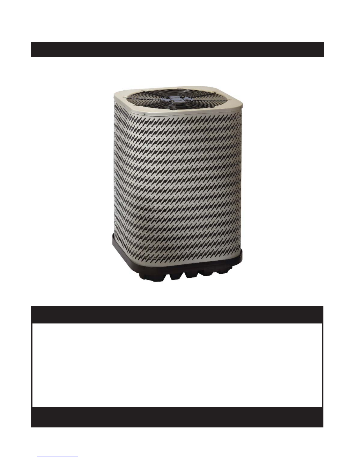
JT5BD Series
USER’S MANUAL / INSTALLATION INSTRUCTIONS
SPLIT SYSTEM HEAT PUMP - R-22
13 SEER
Please read this information thoroughly and become familiar with the capabilities and
use of your appliance before attempting to operate or maintain this unit. Keep this
literature where you have easy access to it in the future. If a problem occurs, check the
instructions and follow recommendations given. If these suggestions don’t eliminate
the problem, call your servicing contractor.
The Installation Instructions are primarily intended to assist qualifi ed individuals
experienced in the proper installation of this appliance. Some local codes require licensed
installation/service personnel for this type of equipment. Please read all instructions
carefully before starting the installation.
DO NOT DESTROY. PLEASE READ CAREFULLY AND
KEEP IN A SAFE PLACE FOR FUTURE REFERENCE.
IMPORTANT

USER INFORMATION
Important Safety Information ....................................3
About the Heat Pump .................................................3
Operating Instructions ...............................................3
Cooling Operation .....................................................3
Heating Operation .....................................................3
Emergency Heat........................................................3
Defrost Operation ......................................................3
Operating the Heat Pump for Automatic
Cooling & Heating .....................................................4
Operating the Indoor Blower Continuously ................4
Turning the Heat Pump Off ........................................4
Heat Pump Maintenance ............................................4
Regular Cleaning.......................................................4
Troubleshooting ..........................................................4
INSTALLER INFORMATION
Important Safety Information ....................................5
Heat Pump Installation ...............................................6
General Information ...................................................6
Before You Install this Unit .........................................6
Locating the Heat Pump ............................................6
Packaging Removal ...................................................6
Ground Level .............................................................6
Connecting Refrigerant Tubing between the
Indoor & Outdoor Unit ...............................................7
Electrical Wiring ..........................................................7
Pre - Electrical Checklist ...........................................7
Line Voltage ...............................................................7
Grounding..................................................................8
Thermostat Connections ...........................................8
Startup & Adjustments ..............................................9
Pre - Start Checklist ..................................................9
Start-up Procedures ..................................................9
Air Circulation - Indoor Blower ...............................9
System Cooling ......................................................9
System Heating ......................................................9
Refrigerant Charging ..................................................9
Charging R-22 Units in AC Mode with
Outdoor Temperatures Above 55° F ........................10
Heat Pump Maintenance ..........................................10
Replacement Parts ...................................................10
WARRANTY INFORMATION
A warranty certifi cate with full details is included with the
Heat Pump. Carefully review these responsibilities with
your dealer or service company. The manufacturer will not
be responsible for any costs found necessary to correct
problems due to improper setup, improper installation,
adjustments, improper operating procedure on the part
of the user, etc. Some specifi c examples of service calls
which are not included in the limited warranty are:
• Correcting wiring problems in the electrical circuit
supplying the Heat Pump.
• Resetting circuit breakers or other switches.
• Adjusting or calibrating of thermostat.
Figures & Tables .......................................................11
Figure 5. Unit Dimensions ...................................11
Refrigerant Charging Charts ...................................11
Figure 6. JT5BD-018K (1.5 Ton Units) ................11
Figure 7. JT5BD-024KA (2 Ton Units) .................12
Figure 8. JT5BD-030KA (2.5 Ton Units) ..............12
Figure 9. JT5BD-036K (3 Ton Units) ...................13
Figure 10. JT5BD-042K (3.5 Ton Units) ..............13
Figure 11. JT5BD-048K (4 Ton Units) .................14
Figure 12. JT5BD-060K (5 Ton Units) .................14
Refrigerant Charging Tables - Cooling Mode ..........15
Table 4. JT5BD-018K (1.5 Ton Units) ..................15
Table 5. JT5BD-024KA (2 Ton Units) ...................15
Table 6. JT5BD-030KA (2.5 Ton Units) ................16
Table 7. JT5BD-036K (3 Ton Units) .....................16
Table 8. JT5BD-042K (3.5 Ton Units) ..................17
Table 9. JT5BD-048K (4 Ton Units) .....................17
Table 10. JT5BD-060K (5 Ton Units) ...................18
Refrigerant Charging Tables - Heating Mode ..........19
Table 11. JT5BD-018K (1.5 Ton Units) ................19
Table 12. JT5BD-024KA (2 Ton Units) .................19
Table 13. JT5BD-030KA (2.5 Ton Units) ..............20
Table 14. JT5BD-036K (3 Ton Units) ...................20
Table 15. JT5BD-042K (3.5 Ton Units) ................21
Table 16. JT5BD-048K (4 Ton Units) ...................21
Table 17. JT5BD-060K (5 Ton Units) ...................22
Electrical Information ...............................................23
Figure 12. JT5BD Wiring Diagram .......................23
Table 18. Electrical Specs & Physical Data ..........24
2
USER INFORMATION
IMPORTANT SAFETY INFORMATION
Safety markings are used frequently throughout this
manual to designate a degree or level of seriousness and
should not be ignored. WARNING indicates a potentially
hazardous situation that if not avoided, could result in
personal injury or death. CAUTION indicates a potentially
hazardous situation that if not avoided, may result in minor
or moderate injury or property damage.
ABOUT THE HEAT PUMP
Your heat pump is a unique, all weather comfort-control
appliance that will heat and cool your home year round
and provide energy saving comfort. It’s an unknown fact
that heat is always in the air, even when the outside
temperature is below freezing. The heat pump uses this
basic law of physics to provide energy saving heat during
the winter months. For example, If the outdoor temperature
is 47° F (8° C), your heat pump can deliver approximately
3.5 units of heat energy per each unit of electrical energy
used, as compared to a maximum of only 1 unit of heat
energy produced with conventional heating systems.
In colder temperatures, the heat pump performs like an air
conditioner run in reverse. Available heat energy outside
the home is absorbed by the refrigerant and exhausted
inside the home. This effi cient process means you only
pay for “moving” the heat from the outdoors to the indoor
area. You do not pay to generate the heat, as is the case
with more traditional furnace designs.
During summer, the heat pump reverses the fl ow of the
heat-absorbing refrigerant to become an energy-effi cient,
central air conditioner. Excess heat energy inside the
home is absorbed by the refrigerant and exhausted
outside the home.
OPERATING INSTRUCTIONS
Please refer to the thermostat manufacturer’s User manual
for detailed programming instructions.
Cooling Operation
1. Set the thermostat’s system mode to COOL or AUTO
and change the fan mode to AUTO. See Figure 1
2. Set the temperature selector to the desired temperature
level. The outdoor fan, compressor, and blower motor will
all cycle on and off to maintain the indoor temperature
at the desired cooling level.
NOTE: If the temperature level is re-adjusted, or the
system mode is reset, the fan and compressor in the
outdoor unit may not start immediately. A protective
timer circuit holds the compressor and the outdoor fan
off for approximately 5 minutes following a previous
operation or the interruption of the main electrical
power.
Heating Operation
1. Set the thermostat’s system mode to HEAT or AUTO
and change the fan mode to AUTO. See Figure 1.
2. Set the temperature selector to the desired temperature
level. The compressor, outdoor fan, and blower motor
will cycle on and off to maintain the indoor temperature
at the desired heating level.
NOTE: If the temperature level is re-adjusted, or the
system mode is reset, the fan and compressor in the
outdoor unit may not start immediately. A protective
timer circuit holds the compressor and the outdoor fan
off for approximately 5 minutes following a previous
operation or the interruption of the main electrical
power.
Emergency Heat
Some thermostats may include a system mode called EM
HT or AUX HT, etc. This is a back-up heating mode that
should only be used if a problem is suspected. With the
mode set to EM HT, etc., the compressor and outdoor fan
will be locked off and supplemental heat (electric resistance
heating) will be used as a source of heat. Sustained use
of electric resistance heat in place of the heat pump will
result in an increase in electric utility costs.
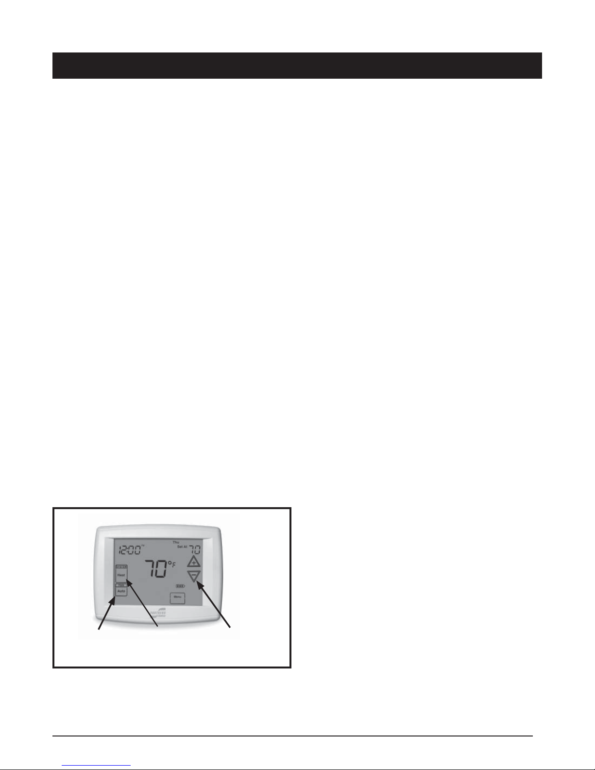
Fan
Mode
Figure 1. Digital Thermostat
System
Mode
Temperature
Selector
Defrost Operation
During cold weather heating operation, the outdoor unit
will develop a coating of snow and ice on the heat transfer
coil. This is normal and the unit will defrost itself. This unit
monitors ambient and coil temperatures to regulate the
defrost function accordingly.
3
USER INFORMATION
At the beginning of the defrost cycle, both the outdoor
condenser fan and compressor will turn off. After
approximately 30 seconds, the compressor will turn on
and begin to heat the outdoor coil causing the ice and
snow to melt.
NOTE: While the ice and snow is melting, some steam
may rise from the outdoor unit as the warm coil causes the
melting frost to evaporate. When defrost is completed, the
outdoor fan motor will start, and the compressor will turn
off again. In approximately 30 seconds the compressor
will start up again and continue normal operation.
Operating the Heat Pump for Automatic Cooling
and Heating
1. Set the thermostat system switch to AUTO and the
thermostat fan switch to AUTO. See Figure 1.
NOTE: Thermostat styles vary. Some models will
not include the AUTO mode and others will have the
AUTO in place of the HEAT and COOL. Others may
include all three. Refer to the instructions supplied
with your thermostat for specifi c instructions.
2. Set the thermostat temperature to the desired
temperature level. The outdoor unit and the indoor blower
will then cycle on and off in either the heating or cooling
mode of operation as required to automatically maintain
the indoor temperature within the desired limits.
Operating the Indoor Blower Continuously
The continuous indoor blower operation is typically used to
circulate the indoor air to equalize a temperature unbalance
due to a sun load, cooking, or fi replace operation.
Set the thermostat fan mode to ON (Figure 1). The indoor
blower starts immediately, and will run continually until
the fan mode is reset to AUTO.
The continuous indoor blower operation can be obtained
with the thermostat system mode set in any position,
including OFF.
HEAT PUMP MAINTENANCE
CAUTION:
Shut off all electrical power to the unit before
performing any maintenance. Failure to comply
may result in personal injury or death.
Proper maintenance is most important to achieve the best
performance from the appliance and should be performed
by a qualifi ed service technician at least once a year. Read
the maintenance items below and follow the instructions
for years of safe, trouble free operation.
Regular Cleaning
WARNING:
Do not place combustible material on or against
the unit cabinet. Do not place combustible
materials, including gasoline and any other
fl ammable vapors and liquids, in the vicinity of
the unit.
• Clean or replace the indoor air fi lter at the start of each
heating and cooling season, and when an accumulation
of dust and dirt is visible on the air fi lter.
• Remove any leaves and grass clippings from around
the coil of the outdoor unit, being careful not to damage
the aluminum fi ns.
• Check and remove any obstructions, such as twigs,
sticks, etc.
TROUBLESHOOTING
If the unit fails to operate, check the following:
• The thermostat is properly set. See Cooling Operation
for air conditioning or Heating Operation for furnace.
• The unit disconnect fuses are in good condition and
the electrical power to the unit is turned on.
Turning the Heat Pump Off
Change the thermostat’s system mode to OFF and the fan
mode to AUTO. See Figure 1. NOTE: The system will not
operate, regardless of the temperature selector setting.
4
INSTALLER INFORMATION
IMPORTANT SAFETY INFORMATION
INSTALLER: Please read all instructions before servicing
this equipment. Pay attention to all safety warnings and
any other special notes highlighted in the manual. Safety
markings are used frequently throughout this manual to
designate a degree or level of seriousness and should not
be ignored. WARNING indicates a potentially hazardous
situation that if not avoided, could result in personal injury
or death. CAUTION indicates a potentially hazardous
situation that if not avoided, may result in minor or moderate
injury or property damage.
WARNING:
Shut off all electrical power to the unit before
performing any maintenance or service on the
system. Failure to comply may result in personal
injury or death.
WARNING:
Unless noted otherwise in these instructions,
only factory authorized parts or accessory
kits may be used with this product. Improper
installation, service, adjustment, or maintenance
may cause explosion, fi re, electrical shock or
other hazardous conditions which may result in
personal injury or property damage
WARNING:
JT5BD Split System Heat Pumps leave the factory
with a nitrogen holding charge. Follow all charging instructions for maximum unit performance
and effi ciency. Some local codes require licensed
installation/service personnel to service this type
of equipment. Refrigerant charging must be done
by qualifi ed personnel familiar with safe and environmentally responsible refrigerant handling
procedures. Under no circumstances should
the owner attempt to install and/or service this
equipment. Failure to comply with this warning
could result in property damage, personal injury,
or death.
CAUTION:
This unit uses refrigerant R-22. DO NOT use
any other refrigerant in this unit. Use of another
refrigerant will damage the unit.
WARNING:
The information listed below must be followed
during the installation, service, and operation
of this unit. Unqualifi ed individuals should
not attempt to interpret these instructions or
install this equipment. Failure to follow safety
recommendations could result in possible
damage to the equipment, serious per
injury or death
• The installer must comply with all local codes and
regulations which govern the installation of this type
of equipment. Local codes and regulations take
precedence over any recommendations contained in
these instructions. Consult local building codes and
the National Electrical Code (ANSI CI) for special
installation requirements.
• All electrical wiring must be completed in accordance
with local, state and national codes and regulations
and with the National Electric Code (ANSI/NFPA 70)
or in Canada the Canadian Electric Code Part 1 CSA
C.22.1.
• This equipment contains liquid and gaseous refrigerant
under high pressure. DO NOT USE ANY PORTION OF
THE CHARGE FOR PURGING OR LEAK TESTING.
Installation or servicing should only be performed by
qualifi ed trained personnel thoroughly familiar with this
type equipment.
• Fully annealed, refrigerant grade copper tubing should
be used when installing the system. Refrigerant suction
line tubing should be fully insulated.
• Installation of equipment may require brazing
operations. Installer must comply with safety codes
and wear appropriate safety equipment (safety glasses,
work gloves, fi re extinguisher, etc.) when performing
brazing operations.
• This unit is designed for outdoor installations only and
should be located as descibed on page 6.
• Follow all precautions in the literature, on tags, and
on labels provided with the equipment. Read and
thoroughly understand the instructions provided with
the equipment prior to performing the installation and
operational checkout of the equipment.
.
sonal
5
HEAT PUMP INSTALLATION
General Information
The JT5BD series Heat Pump is designed only for outdoor
rooftop or ground level installations. This unit has been
tested for capacity and effi ciency in accordance with
A.H.R.I. Standards and will provide many years of safe
and dependable comfort, providing it is properly installed
and maintained. Abuse, improper use, and/or improper
maintenance can shorten the life of the appliance and
create unsafe hazards.
To achieve optimum performance and minimize equipment
failure, it is recommended that periodic maintenance be
performed on this unit. The ability to properly perform
maintenance on this equipment requires certain
mechanical skills and tools.
Before You Install this Unit
The cooling load of the area to be conditioned must be
calculated and a system of the proper capacity selected.
It is recommended that the area to be conditioned be
completely insulated and vapor sealed.
Check the electrical supply and verify the power supply
is adequate for unit operation. The system must be wired
and provided with circuit protection in accordance with
local building codes. If there is any question concerning
the power supply, contact the local power company.
The indoor section (air handler, furnace, etc) should be
installed before routing the refrigerant tubing. Refer to
the indoor unit's installation instructions for installation
details.
All units are securely packed at the time of shipment and
upon arrival should be carefully inspected for damage
prior to installing the equipment at the job site. Verify
coil fi ns are straight. If necessary, comb fi ns to remove
fl attened or bent fi ns. Claims for damage (apparent or
concealed) should be fi led immediately with the carrier.
Please consult your dealer for maintenance information
and availability of maintenance contracts. Please read
all instructions before installing the unit.
Locating the Heat Pump
• Survey the job site to determine the best location for
mounting the outdoor unit. See Figure 5 (page 11) for
unit dimensions.
• Overhead obstructions, poorly ventilated areas, and
areas subject to accumulation of debris should be
avoided.
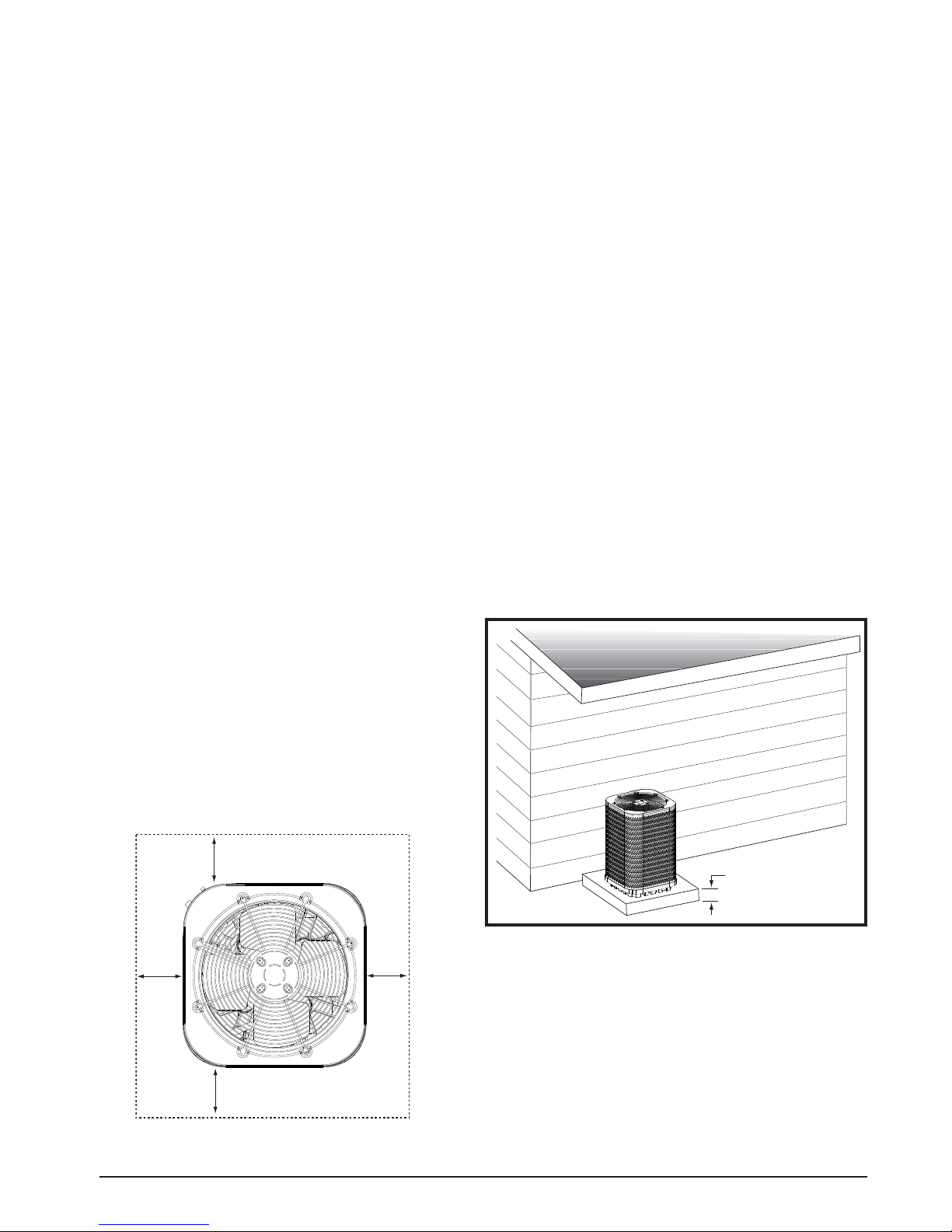
• Suffi cient clearance for unobstructed airfl ow through the
outdoor coil must be maintained in order to achieve rated
performance. See Figure 2 for minimum clearances to
obstructions.
• Consideration should be given to availability of electric
power, service access, noise, and shade.
Packaging Removal
NOTE: To prevent damage to the tubing connections,
carefully remove the carton and user’s manual from the
equipment. Discard the shipping carton.
Ground Level
Ground level installations must be located according to
local building codes or ordinances and these requirements:
• Clearances must be in accordance with those shown
in Figure 2.
• A suitable mounting pad (Figure 3) must be provided
and separate from the building foundation. The pad
must be level and strong enough to support the weight
of the unit. The slab height must be a minimum of 2”
(5 cm) above grade and with adequate drainage.
DO NOT
18"
18"
18"
OBSTRUCT
TOP OF UNIT
Figure 2. Clearance Requirements
6
2”
Figure 3. Ground Level Installation
18"
Connecting Refrigerant Tubing Between the Indoor
& Outdoor Unit
CAUTION:
This system uses R-22 refrigerant with POE
oil. When servicing, cover or seal openings to
minimize the exposure of the refrigerant system
to air to prevent accumulation of moisture and
other contaminants.
After outdoor and indoor unit placement has been
determined, route refrigerant tubing between the
equipment in accordance with sound installation practices.
• To maintain the unit's warranty, it is required that a
fi lter drier be installed when the system is open to
the atmosphere. This includes, but is not limited to,
replacing the evaporator and/or condenser of a system.
The fi lter drier must be installed in strict accordance
with the manufacturer’s installation instructions.
• Optional equipment such as liquid line solenoid
valves, low ambient, etc., should be installed in
strict accordance with the manufacturer’s installation
instructions.
ELECTRICAL WIRING
• When connecting refrigerant linesets together, it is
recommended that dry nitrogen be fl owing through
the joints during brazing to prevent internal oxidation
and scaling.
• Refrigerant tubing should be routed in a manner that
minimizes the length of tubing and the number of bends
in the tubing. If precise forming of refrigerant lines is
required, a copper tubing bender is recommended.
Avoid sharp bends and contact of the refrigerant lines
with metal surfaces.
• Refrigerant tubing should be supported in a manner
that the tubing will not vibrate or abrade during system
operation.
• Tubing should be kept clean of foreign debris during
installation.
• Every effort should be made by the installer to ensure
that the fi eld installed refrigerant containing components
of the system have been installed in accordance with
these instructions and sound installation practices to
insure reliable system operation and longevity.
• The maximum recommended interconnecting
refrigerant line lengths is 75 ft. and the vertical elevation
difference between the indoor and outdoor sections
should not exceed 20 ft.
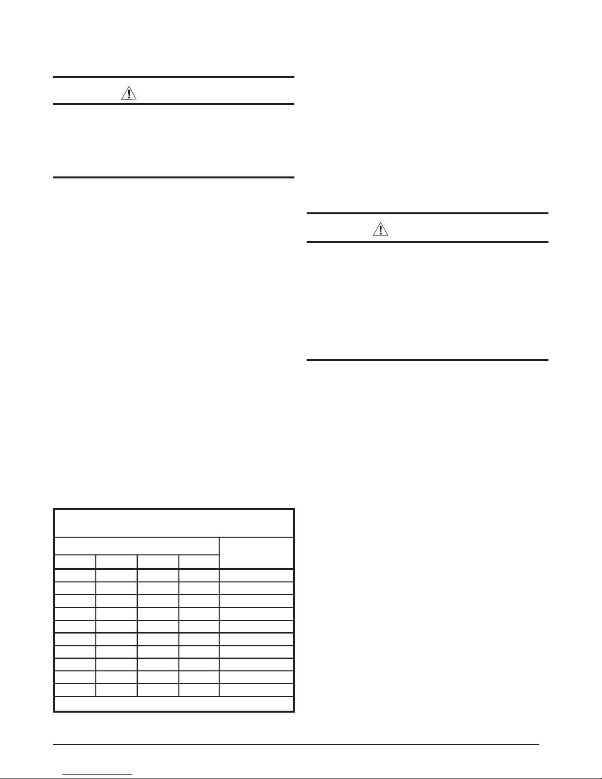
COPPER WIRE SIZE — AWG
(1% Voltage Drop)
Supply Wire Length-Feet
200 150 100 50
6 8 10 14 15
46812 20
46810 25
44610 30
3468 35
3468 40
2346 45
2346 50
2346 55
1234 60
Wire Size based on N.E.C. for 60° type copper conductors.
Table 1. Copper Wire Size
Supply Circuit
Ampacity
WARNING:
To avoid risk of electrical shock, personal injury,
or death, disconnect all electrical power to the unit
before performing any maintenance or service.
The unit may have more than one electrical
supply.
Label all wires prior to disconnection when
servicing the unit. Wiring errors can cause
improper and dangerous operation.
• All electrical connections must be in compliance with
all applicable local codes and ordinances, and with
the current revision of the National Electric Code
(ANSI/NFPA 70).
• For Canadian installations the electrical connections
and grounding shall comply with the current Canadian
Electrical Code (CSA C22.1 and/or local codes).
Pre-Electrical Checklist
Verify that the voltage, frequency, and phase of the
supply source match the specifi cations on the unit
rating plate. See Table 18 (page 24).
Verify that the service provided by the utility is suffi cient
to handle the additional load imposed by this equipment.
Refer to the unit wiring label for proper voltage wiring.
Verify factory wiring is in accordance with the unit
wiring diagram or Figure 13 (page 23). Inspect for
loose connections.
Line Voltage
• A wiring diagram is located on the inside cover of the
electrical box of the outdoor unit. The installer should
become familiar with the wiring diagram before making
any electrical connections to the outdoor unit.
• An electrical disconnect must be located within
sight of and readily accessible to the unit. This
switch shall be capable of electrically de-energizing
the outdoor unit.
• Line voltage to the unit should be supplied from a
dedicated branch circuit containing the correct fuse
or circuit breaker for the unit. Incoming fi eld wiring
and minimum size of electrical conductors and circuit
7
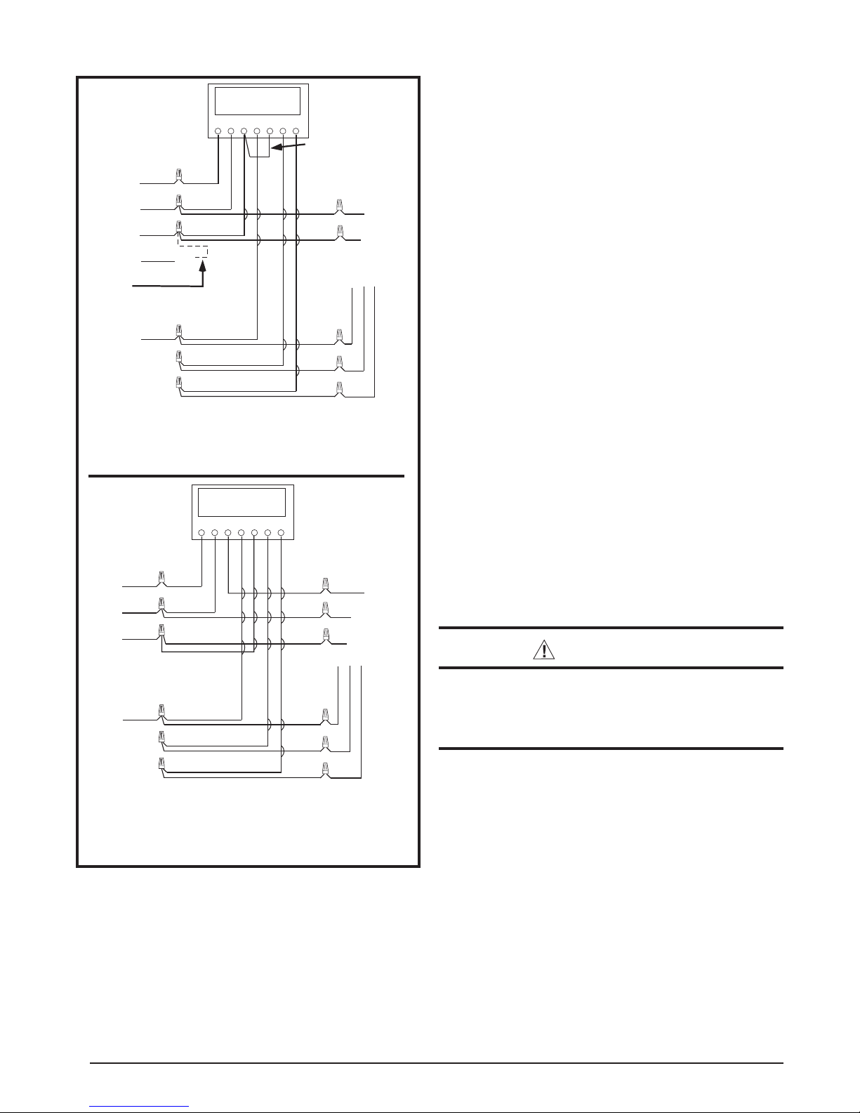
Thermostat
GRW2CEOY
NOTE: Jumper
between W2 and E is
required when no OD
T-Stat is used.
For 2-Stage
Heater
Kits
Green
Red
Brown
Orange
Black
G
R
W
W
2
C
Air Handler Heat Pump OD
Section
Typical Heat Pump with Standard Air Handler
Thermostat
GRW2CEOY
Red
G
R
W
C
C
Green
White
Black
C
W
O Y
OY
E
R
2
protection must be in compliance with information listed
on the outdoor unit data label. Any other wiring methods
must be acceptable to authority having jurisdiction.
• The outdoor unit requires both power and control circuit
electrical connections. Refer to the wiring diagram /
schematic for identifi cation and location of outdoor unit
fi eld wiring interfaces Figure 13 (page 23). Make all
electrical connections in accordance with all applicable
R
W
2
codes and ordinances.
• Overcurrent protection must be provided at the branch
circuit distribution panel and sized as shown on the unit
rating label and according to applicable local codes.
See the unit rating plate for minimum circuit ampacity
and maximum overcurrent protection limits.
• Provide power supply for the unit in accordance with the
unit wiring diagram, and the unit rating plate. Connect
the line-voltage leads to the terminals on the contactor
inside the control compartment.
• Use only copper wire for the line voltage power supply
to this unit as listed in Table 1. Use proper code agency
listed conduit and a conduit connector for connecting
the supply wires to the unit. Use of rain tight conduit
is recommended.
• 208/230 Volt units are shipped from the factory wired
for 230 volt operation. For 208V operation, remove the
lead from the transformer terminal marked 240V and
connect it to the terminal marked 208V.
• Optional equipment requiring connection to the power
or control circuits must be wired in strict accordance
of the NEC (ANSI/NFPA 70), applicable local codes,
and the instructions provided with the equipment.
Grounding
WARNING:
The unit cabinet must have an uninterrupted or
unbroken electrical ground to minimize personal
injury if an electrical fault should occur. Do not
use gas piping as an electrical ground
!
Air Handler Heat Pump OD
Typical Heat Pump with
Outdoor Thermostat and Air Handler
Figure 4. Typical Thermostat Connections
8
Section
This unit must be electrically grounded in accordance
with local codes or, in the absence of local codes, with
the National Electrical Code (ANSI/NFPA 70) or the CSA
C22.1 Electrical Code. Use the grounding lug provided in
the control box for grounding the unit.
Thermostat Connections
• Thermostat connections should be made in accordance
with the instructions supplied with the thermostat and
the indoor equipment.
• The outdoor unit is designed to operate from a 24 VAC
Class II control circuit. The control circuit wiring must
comply with the current provisions of the NEC (ANSI/
NFPA 70) and with applicable local codes having
jurisdiction.
• The low voltage wires must be properly connected
to the units low voltage terminal block (Figure 4).
 Loading...