

Page 1
Outdoor Air Conditioner
User’s Information and Installation Instructions
13 SEER R-410A High Effi ciency Split System
These units have been designed and tested for
capacity & effi ciency in accordance with A.H.R.I.
Standards. Split System Air Conditioning units
are designed for use with a wide variety of fossil
fuel furnaces, electric furnaces, air handlers, and
evaporator coil combinations.
These instructions are primarily intended to assist
qualifi ed individuals experienced in the proper
installation of heating and/or air conditioning
appliances. Some local codes require licensed
installation/service personnel for this type of
equipment. Read all instructions carefully before
starting the installation.
USER’S INFORMATION
IMPORTANT
Read this owner information to become familiar
with the capabilities and use of your appliance.
Keep this with literature on other appliances
where you have easy access to it in the future.
If a problem occurs, check the instructions
and follow recommendations given. If these
suggestions don’t eliminate your problem, call
your servicing contractor .
OPERATING INSTRUCTIONS
To Operate Your Furnace for
Heating —
1. Set the thermostat system switch to HEAT
or AUTO and the thermostat fan switch to
AUTO. (See Figure 1)
2. Set the thermostat temperature to the
desired temperature level by pressing the
WARMER or COOLER button. Please refer
to the separate detailed user’s manual
for complete thermostat programming
instructions. The fur nace and indoor blower
will cycle on and off to maintain the indoor
temperature at the desired heating level.
To Shut Off Your Air Conditioner —
Set the thermostat system switch to OFF and the
thermostat fan switch to AUTO. (See Figure 1)
The system will not operate, regardless of the
thermostat temperature setting.
To Operate the Indoor Blower
Continuously —
Set the thermostat fan switch to ON (See
Figure 1)
To Operate Your Air Conditioner for
Cooling —
1. Set the thermostat system switch to COOL
or AUTO and the thermostat fan switch to
AUTO. (See Figure 1)
2. Set the thermostat temperature to the
desired temperature level by pressing the
WARMER or COOLER button. Please refer
to the separate detailed thermostat user’s
manual for complete instructions regarding
thermostat programming. The outdoor unit
and indoor blower will both cycle on and
off to maintain the indoor temperature at
the desired cooling level.
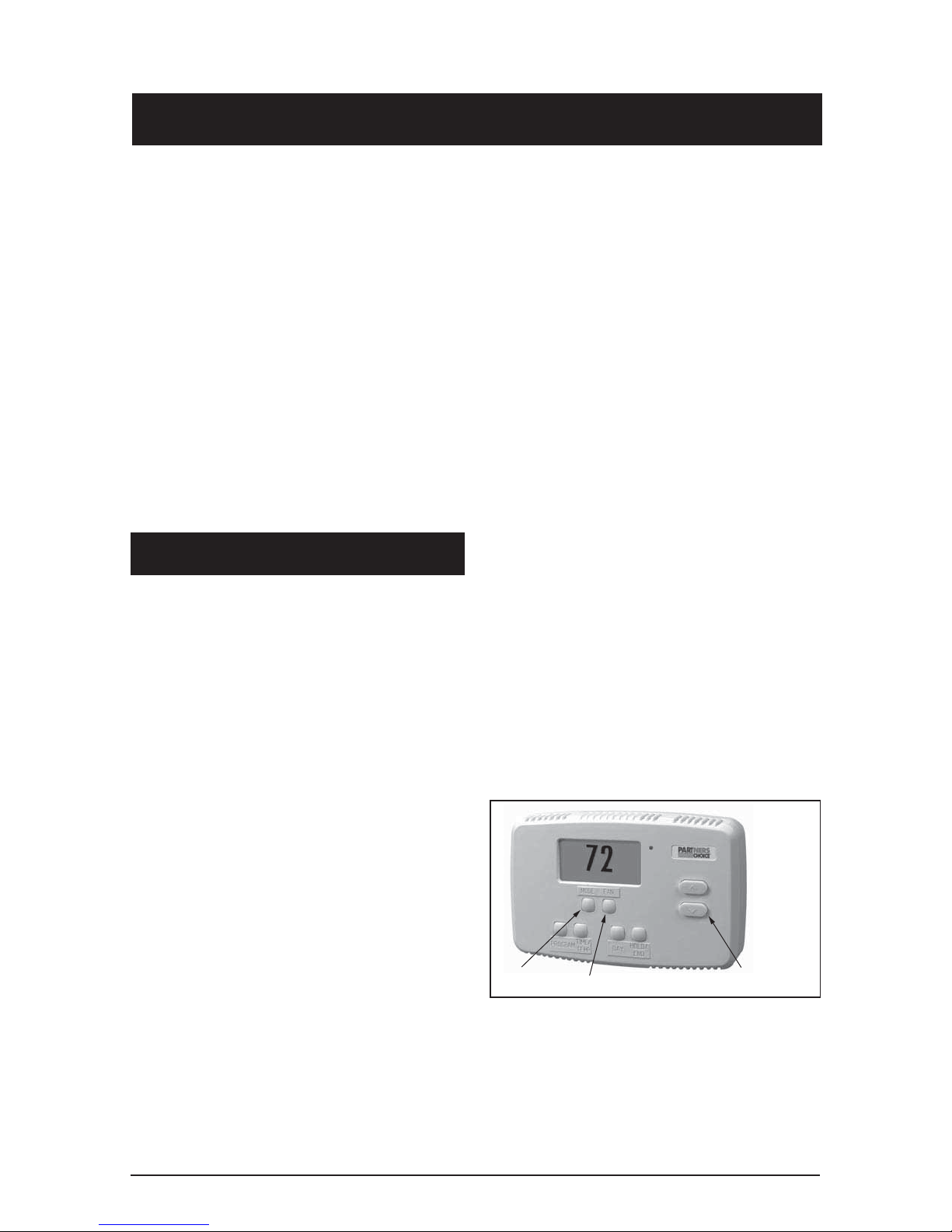
SYSTEM
MODE
FAN
SWITCH
Figure 1. Typical Thermostat
TEMPERATURE
SENSOR
Page 2

2
Page 3
The indoor blower will start immediately, and
will run continually until the fan switch is reset
to AUTO.
The continuous indoor blower operation can be
obtained with the thermostat system switch set
in any position, including OFF.
3. Before Calling a Service Technician, Be
Certain:
a. The unit thermostat is properly set
— see “To Operate Your Air Conditioner for
Cooling” and “To Operate Your Furnace for
Heating.”
The continuous indoor blower operation is
typically used to circulate the indoor air to
equalize a temperature unbalance due to a sun
load, cooking, or fi replace operation.
To Maintain Your Air Conditioner —
CAUTION:
Be certain the electrical power to
the outdoor unit and the furnace/
air handler is disconnected before
doing the following recommended
maintenance.
1. Regularly:
a. Clean or replace the indoor air fi lter at the
start of each heating and cooling season,
and when an accumulation of dust and dirt
is visible on the air fi lter.
b. Remove any leaves and grass clippings
from the coil in the outdoor unit, being
careful not to damage the aluminum fi ns.
c. Check for any obstruction, such as twigs,
sticks, etc.
2. Before Each Cooling Season:
If the furnace/air handler blower motor and
the outdoor unit fan motor(s) have oil tubes
at the motor bearings, apply 10 drops of
SAE No. 20 motor oil to each oil tube.
CAUTION:
Do not over-oil, or oil motors not
factory-equipped with oil tubes. The
compressor is hermetically “sealed”
and does not require lubrication.
b. The unit disconnect fuses are in good
condition, and the electrical power to the
unit is turned on.
1. GENERAL INFORMATION
Read the following instructions completely before
performing the installation.
CAUTION:
This unit uses refrigerant R-410A. DO
NOT under any circumstances use
any other refrigerant besides R-410A
in this unit. Use of another refrigerant
will damage this unit.
Condensing Unit Section — Each condens-
ing unit is shipped with a refrigerant charge
adequate to operate the outdoor section with
an indoor matching coil or air handler, and 15
feet of refrigeration line.
NOTE: DO NOT USE ANY PORTION OF THE
CHARGE FOR PURGING OR LEAK TESTING.
Matching coils and air handlers are shipped with
a small pressurized holding charge to pressurize
them to keep out contaminants. To release the
pressure, read the indoor section installation
instructions carefully.
Liquid and Suction Lines — Refrigerant grade
copper tubing should be used when installing the
system. Refrigerant suction line tubing should
be fully insulated.
Field Connections for Electrical Power
Supply — All wiring must comply with current
provisions of the “National Electrical Code” (ANSI
C1.) and with applicable local codes having
jurisdiction. The minimum size of electrical
conductors and circuit protection must be in
compliance with information listed on the outdoor
unit data label.
3
Page 4
NOTICE:
Certain models have external panels fabricated
from a premium grade of stainless steel designed
to inhibit corrosion. For such units, if the unit is
located in a coastal region or other area subjected
to high concentrations of salt, then the unit should
be hosed off after storms and monthly otherwise
to maintain its new appearance.
2. SAFETY CONSIDERATIONS
Pressures within the System — Split system
air conditioning equipment contains liquid and
gaseous refrigerant under pressure. Installation
and servicing of this equipment should be accomplished by qualifi ed, trained personnel thoroughly
familiar with this type of equipment. Under no
circumstances should the Homeowner attempt
to install and/or service the equipment.
Labels, Tags, Precautions — When working
with this equipment, follow all precautions in the
literature, on tags, and on labels provided with
the equipment. Read and thoroughly understand
the instructions provided with the equipment prior
to performing the installation and operational
checkout of the equipment.
Brazing Operations — Installation of equipment
may require brazing operations. Safety codes
must be complied with. Safety equipment (e.g.;
safety glasses, work gloves, fi re extinguisher,
etc.) must be used when performing brazing
operations.
WARNING:
Ensure all electrical power to the unit
is off prior to installing or servicing
the equipment. Failure to do so may
cause personal injury or death.
3. SITE PREPARATION
the job site. Ensure coil fi ns are straight and, if
necessary, comb fi ns to remove fl attened and
bent fi ns.
Preferred Location of the Outdoor Unit at the
Job Site — Conduct a survey of the job site to
determine the optimum location for mounting
the outdoor unit. Overhead obstructions, poorly
ventilated areas, and areas subject to accumulation of debris should be avoided. The outdoor
unit should be installed no closer than 18 inches
from the outside walls of the facility and in an
area free from overhead obstructions to ensure
unrestricted airfl ow through the outdoor unit.
Facility Prerequisites — Electrical power
must be supplied to the equipment. Electrical
power supplied must be adequate for proper
operation of the equipment. The system must
be wired and provided with circuit protection in
accordance with local building codes and the
National Electrical Code.
4.
INSTALLING THE OUTDOOR UNIT
Slab Mount — The site selected for a slab mount
installation requires a stable foundation and one
not subject to erosion. The slab should be level
and anchored (if necessary) prior to placing the
equipment on the slab.
Cantilever Mount — The cantilever mount
should be designed with adequate safety factor
to support the weight of the equipment, and for
loads subjected to the mount during operation.
Installed equipment should be adequately secured to the cantilever mount and levelled prior
to operation of the equipment.
Roof Mount — The method of mounting should
be designed so as not to overload roof structures
nor transmit noise to the interior of the structure.
Refrigerant and electrical line should be routed
through suitably waterproofed openings to prevent water leaking into the structure.
Unpacking Equipment — Remove the cardboard carton and User’s Manual from the
equipment. Take care not to damage the tubing
connections when removing the carton.
Inspect for Damage — Inspect the equipment
for damage prior to installing the equipment at
4
5. INSTALLING THE INDOOR UNIT
The indoor section should be installed before
proceeding with routing of refrigerant piping.
Consult the installation instructions of the indoor
unit (i.e.: air handler, furnace, etc.) for details
regarding installation.
Page 5
6. CONNECTING REFRIGERANT
TUBING BETWEEN THE
INDOOR AND OUTDOOR UNIT
CAUTION:
This system utilizes R-410A refrigerant
with POE oil. When servicing, cover
or seal openings to minimize the
exposure of the refrigerant system
to air to prevent accumulation of
moisture and other contaminants.
General — Once outdoor and indoor unit place-
ment has been determined, route refrigerant
tubing between the equipment in accordance
with sound installation practices. Refrigerant
tubing should be routed in a manner that minimizes the length of tubing and the number of
bends in the tubing. Refrigerant tubing should
be supported in a manner that the tubing will
not vibrate or abrade during system operation.
Tubing should be kept clean of foreign debris
during installation and installation of a liquid
line fi lter drier is recommended if cleanliness
or adequacy of system evacuation is unknown
or compromised. Every effort should be made
by the installer to ensure that the fi eld installed
refrigerant containing components of the system
have been installed in accordance with these
instructions and sound installation practices
so as to insure reliable system operation and
longevity. The maximum recommended interconnecting refrigerant line length is 75 feet, and the
vertical elevation difference between the indoor
and outdoor sections should not exceed 20 feet.
Consult long line application guide for installations in excess of these limits.
Filter Dryer Installation —A fi lter dryer is
provided with the unit and must be installed in
the liquid line of the system. If the installation
replaces a system with a fi lter dryer already
present in the liquid line, the fi lter dryer must be
replaced with the one supplied. The fi lter dryer
must be installed in strict accordance with the
manufacturer’s installation instructions.
7. MAKING ELECTRICAL
CONNECTIONS
WARNING:
Turn off all electrical power at the main
circuit box before wiring electrical
power to the outdoor unit. Failure to
comply may cause severe personnel
injury or death.
Wiring Diagram/Schematic — A wiring dia-
gram/schematic is located on the inside cover
of the electrical box of the outdoor unit. The
installer should become familiar with the wiring
diagram/schematic before making any electrical
connections to the outdoor unit.
Outdoor Unit Connections — The outdoor
unit requires both power and control circuit
electrical connections. Refer to the unit wiring
diagram/schematic for identifi cation and location
of outdoor unit fi eld wiring interfaces.
Control Circuit Wiring — The outdoor unit is
designed to operate from a 24 VAC Class ll control
circuit. Control circuit wiring must comply with
the current provisions of the “National Electrical
Code” (ANSI C1.) and with applicable local codes
having jurisdiction.
Thermostat Connections — Thermostat connections should be made in accordance with the
instructions supplied with the thermostat, and
with the instructions supplied with the indoor
equipment.
Electrical Power Wiring — Electrical power wiring shall comply with the current provisions of the
“National Electrical Code” (ANSI C1.) and with
applicable local codes having jurisdiction. Use
of rain tight conduit is recommended. Electrical
conductors shall have minimum circuit ampacity in compliance with the outdoor unit rating
label. The facility shall employ electrical circuit
protection at a current rating no greater than that
indicated on the outdoor unit rating label.
Optional Equipment — Optional equipment
(e.g.: fi lter/driers, liquid line solenoid valves, etc.)
should be installed in strict accordance with the
manufacturer’s installation instructions.
Minimum Circuit Ampacity — Electrical wiring
to the equipment must be compatible and in
compliance with the minimum circuit ampacity
listed on the outdoor unit data label.
5
Page 6

Maximum Fuse/Circuit Breaker Size — Circuit
protection for the outdoor unit must be compatible with the maximum fuse/circuit breaker size
listed on the outdoor unit data label.
COPPER WIRE SIZE — AWG
(1% Voltage Drop)
Supply Wire Length-Feet
Supply Circuit
Ampacity200 150 100 50
6 8 10 14 15
4 6 8 12 20
4 6 8 10 25
4 4 6 10 30
Air Filters — Ensure air fi lters are clean and in
place prior to operating the equipment.
Thermostat — Set the room thermostat function
switch to OFF, fan switch to AUTO, and move
temperature setpoint to its highest setting. Prior
to applying electrical power to the outdoor unit,
ensure that the unit has been properly and
securely grounded, and that power supply connections have been made at both the facility
power interface and outdoor unit.
Outdoor Unit — Ensure the outdoor coil and
top of the unit are free from obstructions and
debris, and all equipment access/control panels
are in place.
3468 35
3468 40
2346 45
2346 50
Wire Size based on N.E.C. for 60° type copper
conductors.
Disconnect Switch — An electrically compatible
disconnect switch must be within line of sight of
the outdoor unit. This switch shall be capable of
electrically de-energizing the outdoor unit.
Optional Equipment — Optional equipment requiring connection to the power or control circuits
must be wired in strict accordance with current
provisions of the “National Electrical Code” (ANSI
C1.), with applicable local codes having jurisdiction, and the installation instructions provided
with the equipment. Optional Equipment (e.g.:
liquid line solenoid valves, hard start kits, low
suction pressure cutout switch kit, high pressure cutout switch kit, refrigerant compressor
crankcase heater, etc.) should be installed in
strict accordance with the manufacturer’s installation instructions.
8. STARTUP AND CHECKOUT
WARNING:
Ensure electrical power to the unit is
off prior to performing the following
steps. Failure to do so may cause
personal injury or death.
Using extreme caution, apply power to the unit
and inspect the wiring for evidence of open,
shorted, and/or improperly wired circuits.
Functional Checkout:
CAUTION:
If equipped with a compressor
crankcase heater, wait 24 hours prior
to performing a function checkout to
allow for heating of the compressor
crankcase. Failure to comply may
result in damage and could cause
premature failure of the system.
Indoor Blower — Set the thermostat function
switch to COOLING and the fan switch to ON.
Verify that the indoor blower is operating and
that airfl ow is not restricted. Set the fan switch
back to AUTO.
Blower Time Delay Relay (Select Models):
A time delay relay may be provided with the
unit and must be installed in the indoor section.
The relay will keep the indoor blower running
an additional 40 seconds for increased cooling
effi ciency after the outdoor unit shuts off. The
relay has four terminals and one mounting hole.
Connect terminal “1” to load side of blower relay.
Connect terminal “2” to terminal “R” of T’stat.
Connect terminal “3” to common terminal at
blower relay or transformer. Connect terminal
”4” to terminal “G” on T’stat.
6
Page 7

Low-Pressure Switch —(Select Models) A lowpressure switch is factory-installed and located
in the suction line internal to the outdoor unit.
The switch is designed to protect the compressor
from a loss of charge. Under normal conditions,
the switch is closed. If the suction pressure falls
below 5 psig, then the switch will open and deenergize the outdoor unit. The switch will close
again once the suction pressure increases above
20 psig. Please note that the switch interrupts
the thermostat inputs to the unit. Thus when the
switch opens and then closes, there will be a 5
minute short cycling delay before the outdoor
unit will energize.
High-Pressure Switch—A High-pressure switch
is factory-installed and located in the compressor
discharge line internal to the outdoor unit. The
switch is designed to de-energize the system
when very high pressures occur during abnormal
conditions. Under normal conditions, the switch
is closed. If the discharge pressure rises above
575 psig, then the switch will open and de-energize the outdoor unit. The switch will close again
once the discharge pressure decreases to 460
psig. Please note that the switch interrupts the
thermostat inputs to the unit. Thus, when the
switch opens and then closes, there will be a 5
minute short cycling delay before the outdoor
unit will energize.
ALERT LED (Yellow): communicates an
abnormal system condition through a unique
fl ash code. The ALERT LED will fl ash a number
of times consecutively, pause and then repeat
the process. The number of consecutive
fl ashes, defi ned as the Flash Code, correlates
to a particular abnormal condition. Detailed
descriptions of specifi c ALERT Flash Codes are
shown in Table 1 of this manual.
TRIP LED (Red): indicates there is a demand
signal from the thermostat but no current to the
compressor is detected by the module. The TRIP
LED typically indicates the compressor protector
is open or may indicate missing supply power
to the compressor.
The scroll compressor’s run (R), common (C)
and start (S) wires are routed through the holes
in the Comfort Alert
TM
module marked “R,” “C”
and “S.”
24 VAC Power Wiring — The Comfort Alert
TM
module requires a constant nominal 24 VAC
power supply. The wiring to the module’s R and
C terminals must be directly from the indoor unit
or thermostat.
TM
The Comfort Alert
module requires a thermostat
demand signal to operate properly.
TM
Comfort Alert
— The Comfort Alert
Diagnostics (Select Models)
TM
diagnostics module
facilitates troubleshooting heat pump and air
conditioning system failures. This Comfort
TM
Alert
module is designed only for single-phase
systems with scroll compressors that have
internal overload protection. By monitoring and
analyzing data from the compressor and the
thermostat demand, the module can detect the
cause of electrical and system related failures
without any sensors. A fl ashing LED indicator
communicates the ALERT code and guides the
service technician more quickly and accurately
to the root cause of a problem.
NOTE: This module does not provide safety
TM
protection! The Comfort Alert
module is a
monitoring device and cannot control or shut
down other devices.
LED Description (See Figure 2)
POWER LED (Green): indicates voltage is present
at the power connection of the module.
NOTE: After the thermostat demand signal is
connected, verify that 24 VAC across Y and C
when demand is present.
TROUBLESHOOTING
Interpreting The Diagnostic LEDs – When
an abnormal system condition occurs, the
Comfort AlertTM module displays the appropriate
ALERT and/or TRIP LED will fl ash a number of
times consecutively, pause and then repeat the
process. To identify a Flash Code number, count
the number of consecutive fl ashes.
Every time the module powers up, the last
ALERT Flash Code that occurred prior to shut
down is displayed for one minute. The module
will continue to display the LED until the condition
returns to normal or if 24 VAC power is removed
from the module.
Cooling — Gradually lower the thermostat
temperature setpoint below the actual room
temperature and observe that the outdoor unit
and indoor blower energize. Feel the air being
7
Page 8

circulated by the indoor blower and verify that
it is cooler than ambient temperature. Listen
for any unusual noises. If present, locate and
determine the source of the noise and correct
as necessary.
Heating — If provided with heating equipment,
lower the thermostat setpoint temperature to the
lowest obtainable setting and set the thermostat
function switch to HEATING. The indoor blower
and outdoor unit should stop running. Increase
the setpoint temperature of the thermostat to
the maximum setting. Verify that the heating
equipment has been energized (i.e., fossil fuel
burner operating, etc.) and that the indoor blower
energizes after a short period of time. Feel the
air being circulated by the indoor blower and
verify that it is warmer than ambient temperature.
Listen for any unusual noises. If present, locate
and determine the source of the noise and correct as necessary.
NOTE: Other sources for heating (i.e.: electric
furnace, fossil fuel furnace, air handler with
electric heat options, etc.) that interface with
the unit should be functionally checked to verify
system operation and compatibility. Refer to the
installation instructions for this equipment and
perform a functional checkout in accordance
with the manufacturer’s instructions.
POWER
ALERT
TRIP
8
Figure 2. Comfort Alert
Diagnostics Module
TM
Page 9

Status LED Status LED Description Status LED Troubleshooting Information
Green “POWER” Module has power Supply voltage is present at module terminals
Red “TRIP” Thermostat demand signal
Y is present, but the
compressor is not
running
1. Compressor protector is open
2. Outdoor unit power disconnect is open
3. Compressor circuit breaker or fuse(s) is open
4. Broken wire or connector is not making contact
5. Low pressure switch open if present in system
6. Compressor contactor has failed open
Yellow “ALERT” Long Run Time 1. Low refrigerant charge
Flash Code 1 Compressor is 2. Evaporator blower is not running
running extremely 3. Evaporator coil is frozen
long run cycles 4. Faulty metering device
5. Condenser coil is dirty
6. Liquid line restriction (filter drier blocked if present in system)
7. Thermostat is malfunctioning
8. Comfort Alert Failure
Yellow “ALERT” System Pressure Trip
Flash Code 2 Discharge or suction
pressure out of limits or
compressor overloaded
1. High head pressure
2. Condenser coil poor air circulation (dirty, blocked, damaged)
3. Condenser fan is not running
4. Return air duct has substantial leakage
5. If low pressure switch present in system, check Flash
Code 1 information
Yellow “ALERT” Short Cycling 1. Thermostat demand signal is intermittent
Flash Code 3 Compressor is running 2. Time delay relay or control board defective
only briefly 3. If high pressure switch present go to Flash Code 2 information
4. If low pressure switch present go to Flash Code 1 information
Yellow “ALERT” Locked Rotor
Flash Code 4
1. Run capacitor has failed
2. Low line voltage (contact utility if voltage at disconnect is low)
• Check wiring connections
3. Excessive liquid refrigerant in compressor
4. Compressor bearings are seized
• Measure compressor oil level
Yellow “ALERT” Open Circuit
Flash Code 5
1. Outdoor unit power disconnect is open
2. Compressor circuit breaker or fuse(s) is open
3. Compressor contactor has failed open
• Check compressor contactor wiring and connectors
• Check for compressor contactor failure (burned, pitted or
open)
• Check wiring and connectors between supply and
compressor
• Check for low pilot voltage at compressor contactor coil
4. High pressure switch is open and requires manual reset
5. Open circuit in compressor supply wiring or connections
6. Unusually long compressor protector reset time due to
extreme ambient temperature
7. Compressor windings are damaged
• Check compressor motor winding resistance
Yellow “ALERT” Open Start Circuit 1. Run capacitor has failed
Flash Code 6 Current only in run circuit 2. Open circuit in compressor start wiring or connections
• Check wiring and connectors between supply and the
compressor “S” terminal
3. Compressor start winding is damaged
• Check compressor motor winding resistance
Yellow “ALERT” Open Run Circuit 1. Open circuit in compressor run wiring or connections
Flash Code 7 Current only in start circuit • Check wiring and connectors between supply and the
compressor “R” terminal
2. Compressor run winding is damaged
• Check compressor motor winding resistance
Yellow “ALERT” Welded Contactor 1. Compressor contactor has failed closed
Flash Code 8 Compressor always runs 2. Thermostat demand signal not connected to module
Yellow “ALERT” Low Voltage 1. Control circuit transformer is overloaded
Flash Code 9 Control circuit < 17VAC 2. Low line voltage (contact utility if voltage at disconnect is low)
• Check wiring connections
•
Flash Code number corresponds to a number of LED flashes, followed by a pause and then repeated.
•
TRIP and ALERT LEDs flashing at same time means control circuit voltage is too low for operation.
Table 1. Interpreting the Diagnostic LEDS
9
Page 10

Miswired Module Indication Recommended Troubleshooting Action
Green LED is not on, Determine if both R and C module terminals are
module does not power up connected. Verify voltage is present at module’s R and
C terminals. Review 24VAC Power Wiring (page 4) for
R and C wiring.
Green LED intermittent, Determine if R and Y terminals are wired in reverse.
module powers up only Verify module’s R and C terminals have a constant
when compressor runs source. Review 24VAC Power Wiring (page 4) for R
and C wiring.
TRIP LED is on but system Verify Y terminal is connected to 24VAC at contactor
and compressor check OK coil. Verify voltage at contactor coil falls below 0.5VAC
when off.
TRIP LED and ALERT LED Verify R and C terminals are supplied with 19-28VAC.
flashing together
ALERT Flash Code 3 Verify Y terminal is connected to 24VAC at contactor coil.
(Compressor Short Cycling) Verify voltage at contactor coil falls below 0.5VAC when
displayed incorrectly off.
ALERT Flash Code 5, 6 or 7 Check that compressor run and start wires are through
(Open Circuit, Open Start Circuit module’s current sensing holes. Verify Y terminal is
or Open Run Circuit) displayed connected to 24VAC at contactor coil. Verify voltage at
incorrectly contactor coil falls below 0.5VAC when off.
ALERT Flash Code 6 (Open Check that compressor run and start wires are routed
Start Circuit) displayed for Code 7 through the correct module sensing holes.
(Open Run Circuit) or vice versa
ALERT Flash Code 8 Determine if module’s Y terminal is connected. Verify Y
(Welded Contactor) terminal is connected to 24VAC at contactor coil. Verify
displayed incorrectly 24VAC is present across Y and C when thermostat demand
signal is present. If not, R and C are reverse wired. V erify
voltage at contactor coil falls below 0.5VAC when off.
Table 2. Module Wiring Troubleshooting
Adjustment of Refrigerant Charge:
CAUTION:
Split system air conditioner equipment
contains liquid and gaseous refrigerant
under pressure. Adjustment of
refrigerant charge should only be
attempted by qualified, trained
personnel thoroughly familiar with the
equipment. Under no circumstances
should the homeowner attempt to
install and/or service this equipment.
Failure to comply with this warning
could result in equipment damage,
personal injury, or death.
NOTE: The following Refrigerant Charging
Charts are applicable to matched assemblies
of our equipment and at listed airfl ows for the
indoor coil. These units are matched with TXV
equipped indoor coils. Assemblies of indoor coils
and outdoor units not listed are not recommended
and deviations from rated airfl ows or non-listed
equipment combinations may require modifi cations to the expansion device(s) and refrigerant
charging procedures for proper and effi cient
system operation.
Refrigerant Charging Chart — Refer to
Refrigerant Charging Charts for correct system
charging.
Optional Equipment — A functional checkout
should be performed in accordance with the
checkout procedures supplied with the
equipment.
10
Page 11

Refrigerant Charging Charts For Cooling Mode of Operation
Liquid Temperature (°F)
Liquid Pressure (psig)
Remove
refrigerant
Add
refrigerant
S4BD-018KA/KB
600
575
550
525
500
475
450
425
400
375
Liquid Pressure (psig)
350
325
300
275
250
70 75 80 85 90 95 100 105 110 115 120 125 130
Remove refrigerant when above the curve
Add refrigerant when below the curve
Liquid Temperature (F)
S4BD-024KA/KB
600
575
550
525
500
475
450
425
SATURATION
400
375
350
325
300
275
250
75 80 85 90 95 100 105 110 115 120 125 130 135
*Note: All pressures are listed in psig. and all temperatures in deg. F.
11
Page 12

Liquid Temperature (°F)
Liquid Pressure (psig)
Remove
refrigerant
Add
refrigerant
Liquid Temperature (°F)
Liquid Pressure (psig)
Remove
refrigerant
Add
refrigerant
S4BD-030KA/KB
600
575
550
525
500
475
450
425
400
375
350
325
300
275
250
Refrigerant Charging Charts For
Cooling Mode of Operation (Continued)
SATURATION
75 80 85 90 95 100 105 110 115 120 125 130 135
S4BD-036KA/KB
600
575
550
525
500
475
450
425
SATURATION
400
375
350
325
300
275
250
75 80 85 90 95 100 105 110 115 120 125 130 135
*Note: All pressures are listed in psig. and all temperatures in deg. F.
12
Page 13

Refrigerant Charging Charts For
Cooling Mode of Operation (Continued)
S4BD-042KA/KB
600
575
550
525
500
475
450
425
400
375
Liquid Pressure (psig)
350
325
300
275
250
70 75 80 85 90 95 100 105 110 115 120 125 130
Remove refrigerant when above the curve
Add refrigerant when below the curve
Liquid Temperature (F)
S4BD-048KA/KB
600
575
550
525
500
475
450
425
400
375
Liquid Pressure (psig)
350
325
300
275
250
70 75 80 85 90 95 100 105 110 115 120 125 130
Remove refrigerant when above the curve
Add refrigerant when below the curve
*Note: All pressures are listed in psig. and all temperatures in deg. F.
Liquid Temperature (F)
13
Page 14

Refrigerant Charging Charts For
Cooling Mode of Operation (Continued)
S4BD-060KA/KB
600
575
550
525
500
475
450
425
400
375
Liquid Pressure (psig)
350
325
300
275
250
70 75 80 85 90 95 100 105 110 115 120 125 130
Remove refrigerant when above the curve
Add refrigerant when below the curve
Liquid Temperature (F)
*Note: All pressures are listed in psig. and all temperatures in deg. F.
14
Page 15

15
Page 16

INSTALLER: PLEASE LEAVE THESE
INSTALLATION INSTRUCTIONS
WITH THE HOMEOWNER
¢708659[¤
708659A
708659A (Replaces 7086590)
Specifi cations and illustrations subject to change
without notice and without incurring obligations.
Printed in U.S.A. (12/08)
 Loading...