

NordicTrack 831.239490 Owner's Manual
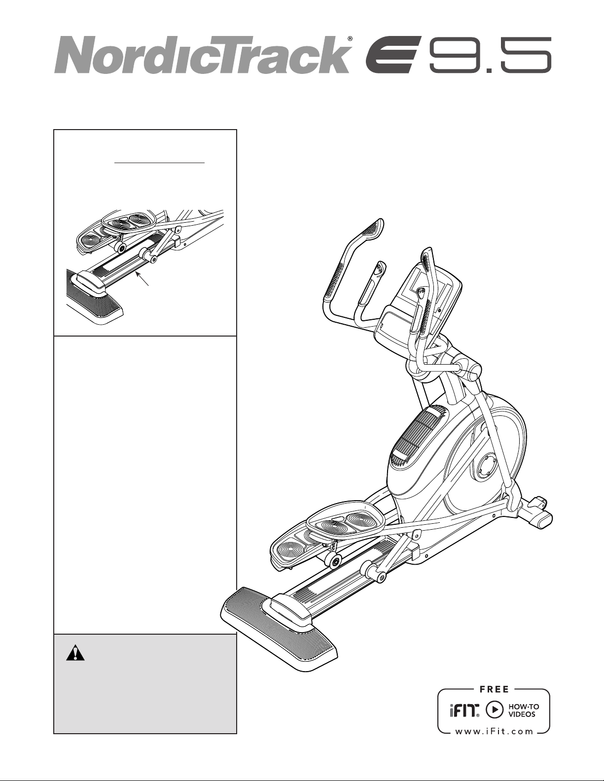
www.nordictrack.com
Model No. 23949.0
Serial No.
Write the serial number in the space
above for reference.
Serial Number
Decal
QUESTIONS?
If you have questions, or if parts
are damaged or missing, DO NOT
CONTACT THE STORE; please
contact Customer Care.
USER’S MANUAL
IMPORTANT: Please register this
product (see the limited warranty
on the back cover of this manual)
before contacting Customer Care.
CALL TOLL-FREE:
1-800-TO-BE-FIT
(1-800-862-3348)
Mon.–Fri., 6 a.m.–6 p.m. MT
Sat. 8 a.m.–4 p.m. MT
ON THE WEB:
www.nordictrackservice.com
CAUTION
Read all precautions and instructions in this manual before using
this equipment. Keep this manual
for future reference.
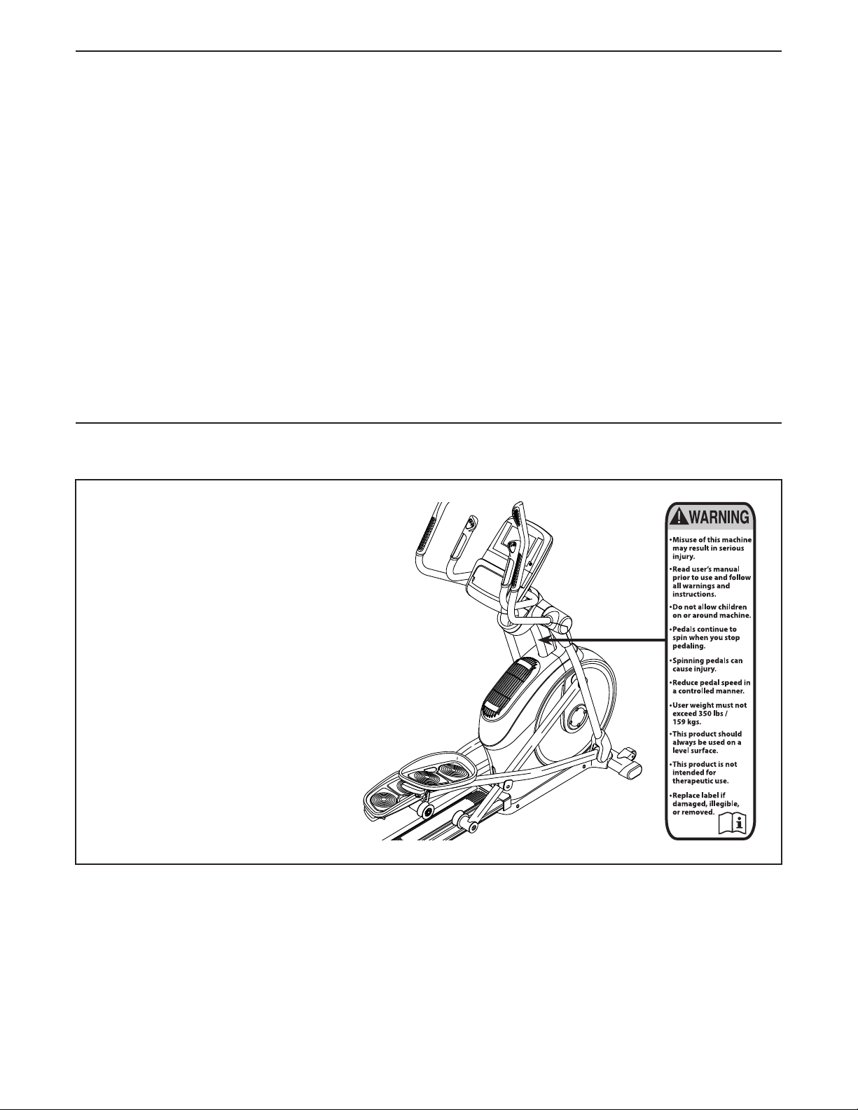
TABLE OF CONTENTS
WARNING DECAL PLACEMENT . . . . . . . . . . . . . . . . . . . . . . . . . . . . . . . . . . . . . . . . . . . . . . . . . . . . . . . . . . . . . . .2
IMPORTANT PRECAUTIONS ..................................................................3
BEFORE YOU BEGIN. . . . . . . . . . . . . . . . . . . . . . . . . . . . . . . . . . . . . . . . . . . . . . . . . . . . . . . . . . . . . . . . . . . . . . . .4
PART IDENTIFICATION CHART. . . . . . . . . . . . . . . . . . . . . . . . . . . . . . . . . . . . . . . . . . . . . . . . . . . . . . . . . . . . . . . .5
ASSEMBLY . . . . . . . . . . . . . . . . . . . . . . . . . . . . . . . . . . . . . . . . . . . . . . . . . . . . . . . . . . . . . . . . . . . . . . . . . . . . . . . .6
THE CHEST HEART RATE MONITOR. . . . . . . . . . . . . . . . . . . . . . . . . . . . . . . . . . . . . . . . . . . . . . . . . . . . . . . . . .15
HOW TO USE THE ELLIPTICAL ..............................................................16
FCC INFORMATION . . . . . . . . . . . . . . . . . . . . . . . . . . . . . . . . . . . . . . . . . . . . . . . . . . . . . . . . . . . . . . . . . . . . . . . .27
MAINTENANCE AND TROUBLESHOOTING .....................................................28
EXERCISE GUIDELINES ....................................................................29
PART LIST. . . . . . . . . . . . . . . . . . . . . . . . . . . . . . . . . . . . . . . . . . . . . . . . . . . . . . . . . . . . . . . . . . . . . . . . . . . . . . . .31
EXPLODED DRAWING. . . . . . . . . . . . . . . . . . . . . . . . . . . . . . . . . . . . . . . . . . . . . . . . . . . . . . . . . . . . . . . . . . . . . .33
ORDERING REPLACEMENT PARTS .................................................. Back Cover
LIMITED WARRANTY. . . . . . . . . . . . . . . . . . . . . . . . . . . . . . . . . . . . . . . . . . . . . . . . . . . . . . . . . . . . . . . Back Cover
WARNING DECAL PLACEMENT
This drawing shows the location(s)
of the warning decal(s). If a decal is
missing or illegible, see the front
cover of this manual and request
a free replacement decal. Apply
the decal in the location shown.
Note: The decal(s) may not be
shown at actual size.
NORDICTRACK is a registered trademark of ICON IP, Inc.
2

IMPORTANT PRECAUTIONS
WARNING: To reduce the risk of serious injury, read all important precautions and
instructions in this manual and all warnings on your elliptical before using your elliptical. ICON
assumes no responsibility for personal injury or property damage sustained by or through the use of
this product.
1. It is the responsibility of the owner to ensure
that all users of the elliptical are adequately
informed of all precautions.
2. Before beginning any exercise program,
consult your physician. This is especially
important for persons over age 35 or persons with pre-existing health problems.
3. Use the elliptical only as described in this
manual.
4. The elliptical is intended for home use only.
Do not use the elliptical in a commercial,
rental, or institutional setting.
5. Keep the elliptical indoors, away from moisture and dust. Do not put the elliptical in a
garage or covered patio, or near water.
6. Place the elliptical on a level surface, with at
least 3 ft. (0.9 m) of clearance in the front and
rear of the elliptical and 2 ft. (0.6 m) on each
side. To protect the floor or carpet from damage, place a mat under the elliptical.
9. The elliptical should not be used by persons
weighing more than 350 lbs. (159 kg).
10. Wear appropriate clothes while exercising;
do not wear loose clothes that could become
caught on the elliptical. Always wear athletic
shoes for foot protection while exercising.
11. Hold the handlebars or the upper body arms
when mounting, dismounting, or using the
elliptical.
12. The heart rate monitor is not a medical
device. Various factors may affect the accuracy of heart rate readings. The heart rate
monitor is intended only as an exercise aid
in determining heart rate trends in general.
13. The elliptical does not have a freewheel; the
pedals will continue to move until the flywheel stops. Reduce your pedaling speed in
a controlled way.
14. Keep your back straight while using the elliptical; do not arch your back.
7. Inspect and properly tighten all parts regularly. Replace any worn parts immediately.
8. Keep children under age 12 and pets away
from the elliptical at all times.
15. Over exercising may result in serious injury
or death. If you feel faint or if you experience
pain while exercising, stop immediately and
cool down.
3
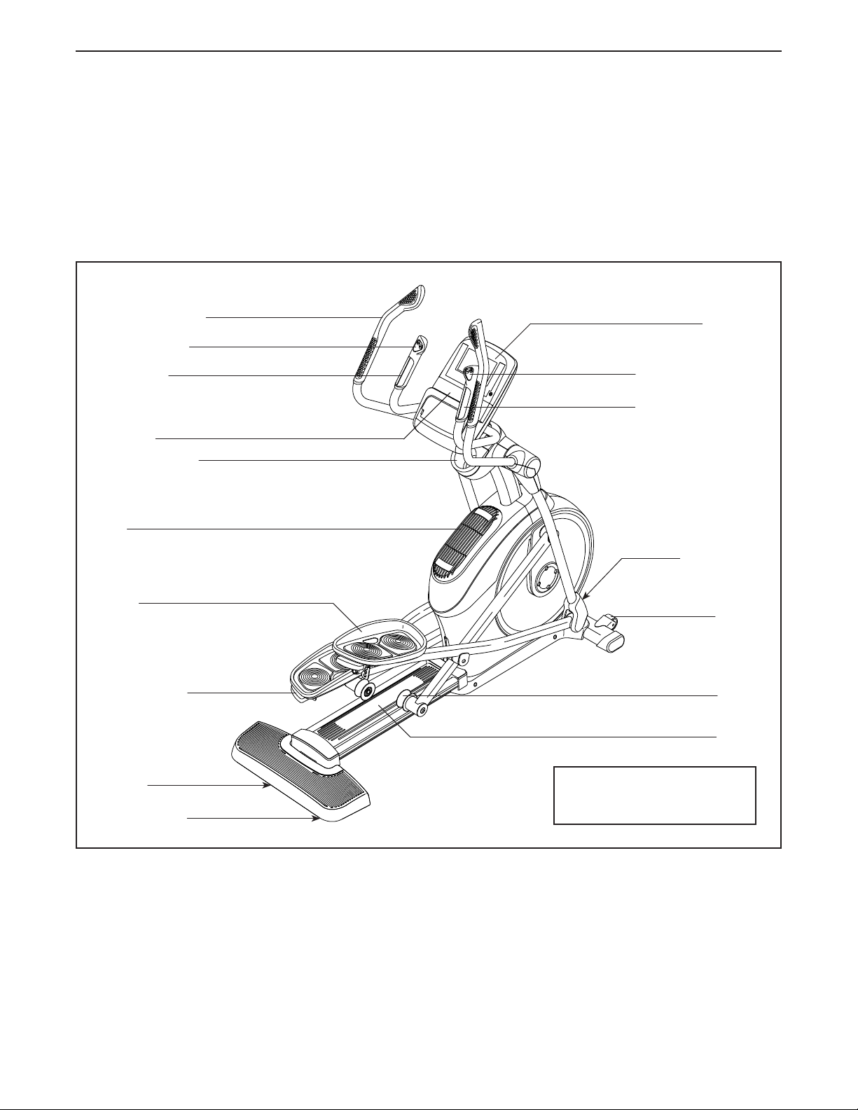
BEFORE YOU BEGIN
Thank you for selecting the revolutionary
NORDICTRACK® E 9.5 elliptical. The E 9.5 elliptical
provides an impressive selection of features designed
to make your workouts at home more effective and
enjoyable.
For your benefit, read this manual carefully before
you use the elliptical. If you have questions after
Upper Body Arm
Ramp Control
Handlebar
Speaker
Accessory Tray
reading this manual, please see the front cover of this
manual. To help us assist you, note the product model
number and serial number before contacting us. The
model number and the location of the serial number
decal are shown on the front cover of this manual.
Before reading further, please familiarize yourself with
the parts that are labeled in the drawing below.
Console
Resistance Control
Heart Rate Monitor
Fan
Pedal
Pedal Handle
Handle
Leveling Foot
Power Switch/
Power Cord
Wheel
Roller
Ramp
Length: 5 ft. 8 in. (173 cm)
Width: 2 ft. 2 in. (66 cm)
4
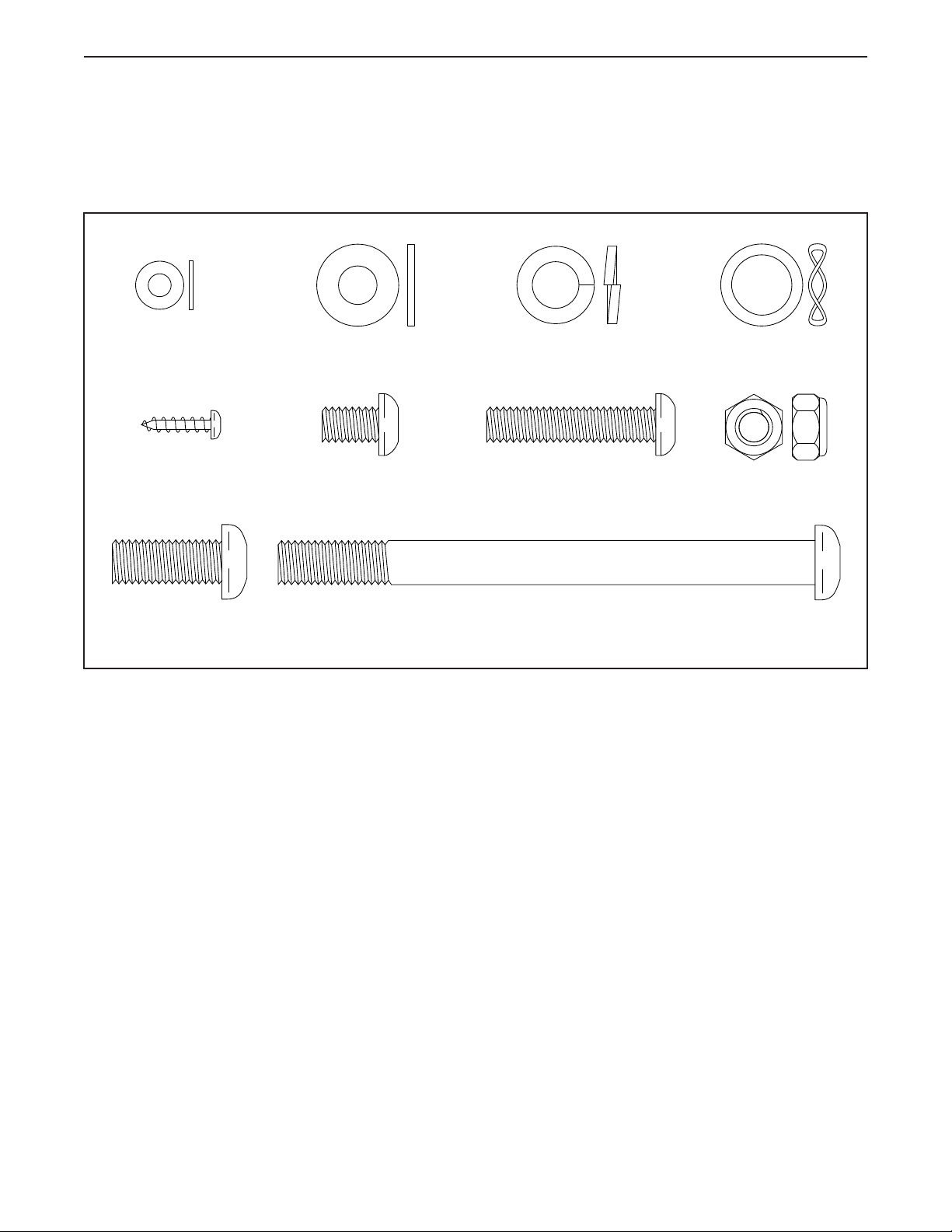
PART IDENTIFICATION CHART
Use the drawings below to identify the small parts needed for assembly. The number in parentheses below each
drawing is the key number of the part, from the PART LIST near the end of this manual. The number following the
key number is the quantity needed for assembly. Note: If a part is not in the hardware kit, check to see if it
has been preassembled. Extra parts may be included.
M5 Washer
(94)–2
M4 x 16mm
Screw (101)–16
M10 x 25mm
Screw (99)–4
M8 Washer
(97)–8
M8 x 13mm
Screw (82)–8
M10 Split
Washer (105)–8
M8 x 38mm
Bolt (96)–4
M10 x 122mm
Screw (104)–4
16mm Wave
Washer (54)–2
M8 Locknut
(102)–4
5
ASSEMBLY
• To watch an assembly
video, go to
http://productvideo.co/
assembly/sears/nordictrack or use your mobile
phone or smartphone to
read the QR code at the
right.
• Assembly requires two persons.
• Place all parts in a cleared area and remove the
packing materials. Do not dispose of the packing
materialsuntilyounishallassemblysteps.
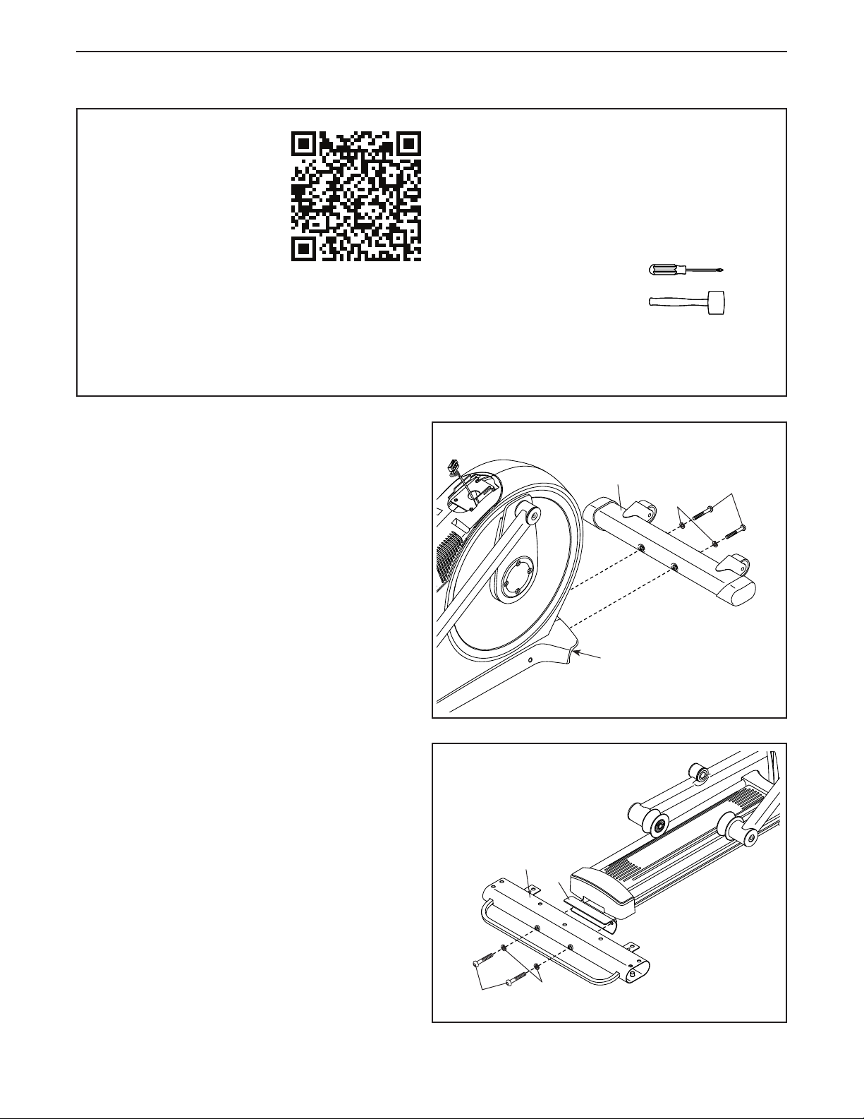
1. With the help of a second person, place some
of the packing materials (not shown) under the
front of the Frame (1). Have the second per-
son hold the Frame to prevent it from tipping
while you complete this step.
Attach the Front Stabilizer (6) to the Frame (1)
with two M10 x 122mm Screws (104) and two
M10 Split Washers (105).
• Left parts are marked “L” or “Left” and right parts
are marked “R” or “Right.”
• To identify small parts, see page 5.
• In addition to the included tool(s), assembly
requires the following tools:
one Phillips screwdriver
one rubber mallet
Assembly may be easier if you have your own set
of wrenches. To avoid damaging parts, do not use
power tools.
1
6
105
104
Remove the packing materials from under the
front of the Frame (1).
2. With the help of a second person, place some of
the packing materials (not shown) under the rear
of the Frame (1). Have the second person hold
the Frame to prevent it from tipping while you
complete this step.
Attach the Rear Stabilizer (2) to the Frame (1)
with two M10 x 122mm Screws (104) and two
M10 Split Washers (105).
Remove the packing materials from under the
rear of the Frame (1).
1
2
2
1
104
105
6
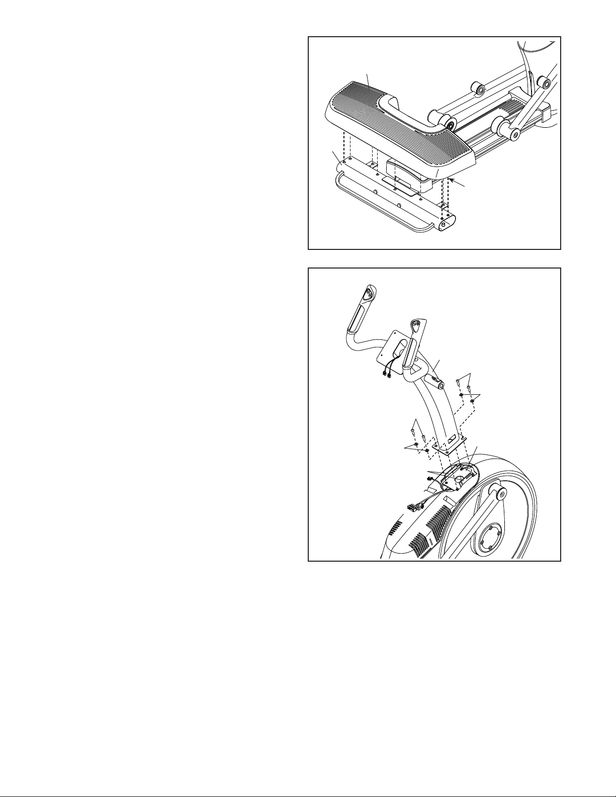
3. Press the Cover Mounts (106) on the underside
of the Rear Stabilizer Cover (15) into the Rear
Stabilizer (2).
3
15
2
106
4. Tip: Avoid pinching the wires. Avoid damag-
ing the indicated plastic tabs. Set the Upright
(4) on the Frame (1).
Attach the Upright (4) with four M10 x 25mm
Screws (99) and four M10 Split Washers (105).
Do not fully tighten the Screws yet.
4
Avoid pinching the
wires and avoid
damaging the tabs
4
99
105
99
105
Tabs
1
7
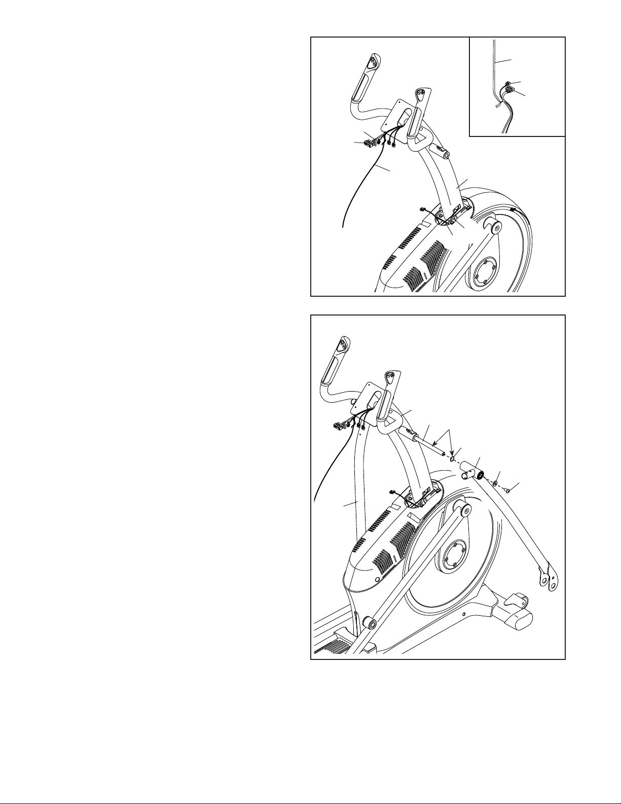
5. See the inset drawing. Locate the wire tie in the
lower end of the Upright (4). Tie the wire tie to
the Upper Wire (110) and to the Fan Extension
Wire (146). Then, pull the upper end of the wire
tie until the Upper Wire and the Fan Extension
Wire are routed through the Upright.
5
Wire Tie
146
110
Tip: To prevent the wires from falling into the
Upright (4), secure the wires with the wire tie.
6. Using a plastic bag to keep your fingers clean,
apply some of the included grease to the Pivot
Axle (35) and to two 16mm Wave Washers (54).
Insert the Pivot Axle (35) through the Upright (4)
and center it. Tip: It may be helpful to use a
rubber mallet.
Identify the Right Upper Body Leg (60) and
orient it as shown.
Slide a 16mm Wave Washer (54) and the Right
Upper Body Leg (60) onto the right side of the
Pivot Axle (35).
146
110
Wire
Tie
6
4
35
4
146
110
Grease
54
60
97
82
Repeat these actions for the Left Upper Body
Leg (46).
Tighten an M8 x 13mm Screw (82) and an M8
Washer (97) into each end of the Pivot Axle (35)
at the same time.
46
8

7. Identify the Right Upper Body Arm (61) and orient it as shown.
Slide the Right Upper Body Arm (61) onto the
Right Upper Body Leg (60).
7
Attach the Right Upper Body Arm (61) with two
M8 x 38mm Bolts (96) and two M8 Locknuts
(102). Make sure that the Locknuts are in the
hexagonal holes.
Repeat this step for the Left Upper Body
Arm (47).
8. Untie and discard the wire tie on the Upper Wire
(110) and the Fan Extension Wire (146).
While a second person holds the Console (7)
near the Upright (4), connect the wires on the
Console to the Upper Wire (110), to the Fan
Extension Wire (146), and to the Sensor Wires
(63, 144).
Insert the excess wire into the Upright (4) or into
the Console (7).
47
Hexagonal
Holes
102
61
8
7
96
144
110
63
146
60
4
9
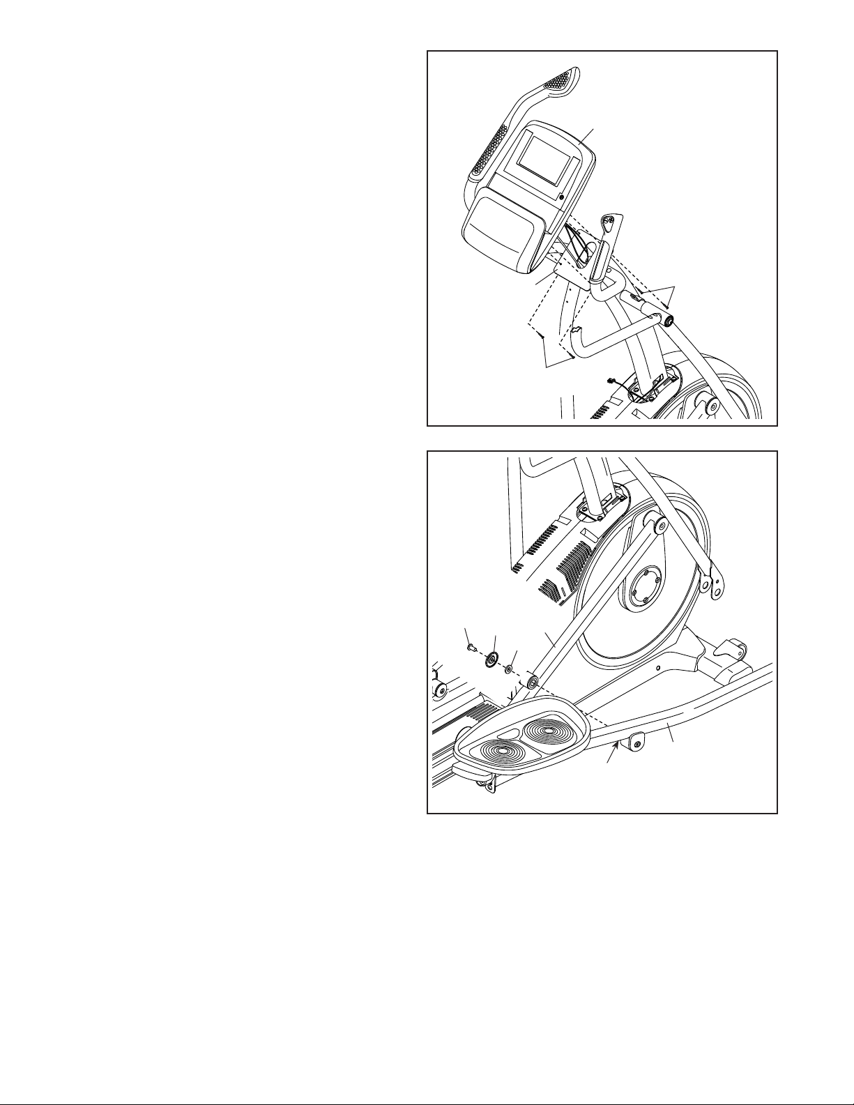
9. Tip: Avoid pinching the wires. Attach the
Console (7) to the Upright (4) with four M4 x
16mm Screws (101).
9
7
Avoid pinching
the wires
10. Orient the Right Pedal Arm (58) assembly as
shown.
Apply grease to the axle on the Right Pedal
Arm (58).
Attach the Right Pedal Arm (58) to the Right
Roller Arm (59) with an M8 x 13mm Screw
(82), a Small Axle Cover (55), and an M8
Washer (97). Tip: Avoid damaging the Small
Axle Cover when tightening the Screw.
Repeat this step for the Left Pedal Arm
assembly (not shown).
10
82
55
97
4
101
59
101
10
58
Grease
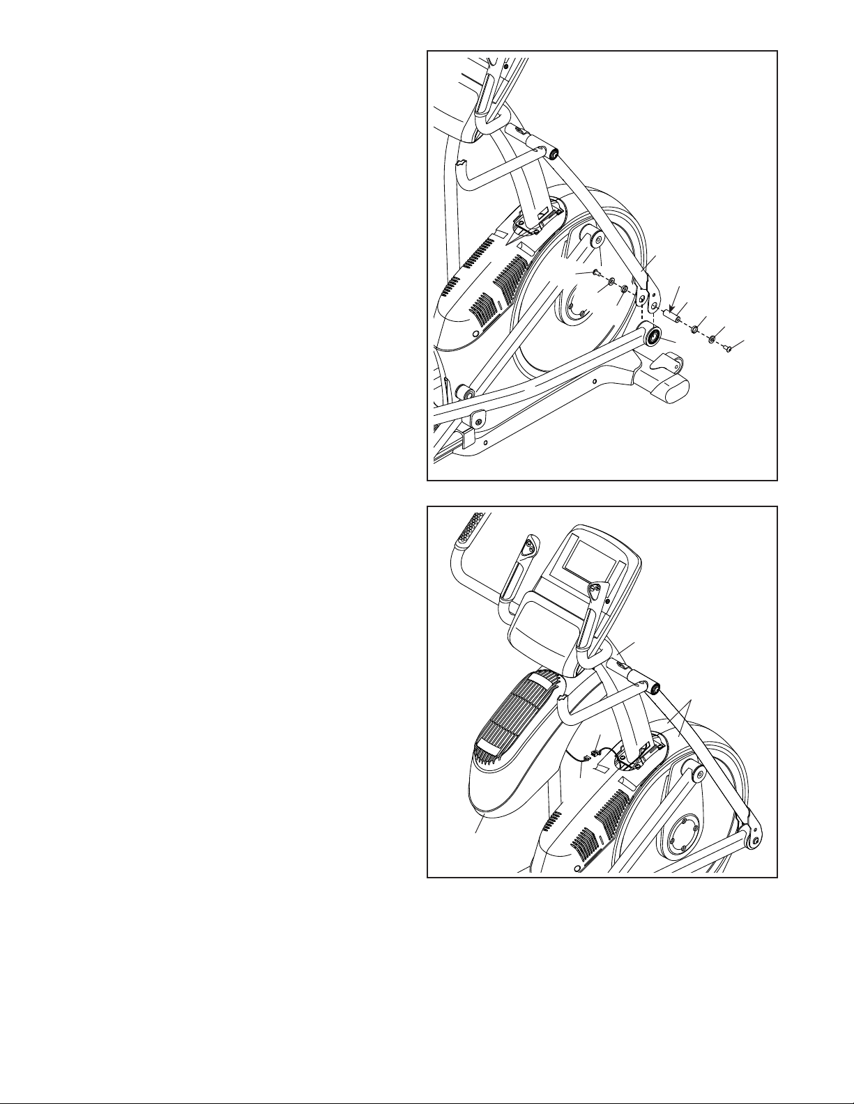
11. Apply grease to a Pedal Arm Axle (64).
Next, slide an M8 Washer (97) and an Axle
Spacer (77) onto an M8 x 13mm Screw (82), and
tighten the Screw a few turns into the Pedal Arm
Axle (64).
While a second person holds the front end of the
Right Pedal Arm (58) inside the bracket on the
Right Upper Body Leg (60), insert the Pedal Arm
Axle (64) into both parts.
11
Slide an M8 Washer (97) and an Axle Spacer
(77) onto another M8 x 13mm Screw (82), and
tighten the Screw a few turns into the Pedal Arm
Axle (64). Then, tighten both Screws at the
same time.
Repeat this step on the other side of the
elliptical.
See assembly step 4. Tighten the M10 x 25mm
Screws (99).
12. Orient the Shield Cover (75) assembly as shown.
While a second person holds the Shield Cover
(75) assembly near the Upright (4), connect the
Fan Extension Wire (146) to the Fan Wire (136).
Tip: Avoid pinching the wires. Press the
Shield Cover (75) onto the Left and Right Shields
(73, 74).
12
99
82
97
77
60
Grease
64
58
Avoid pinching
the wires
4
77
97
82
11
73, 74
146
136
75
 Loading...