

NordicTrack 308500 Owner's Manual
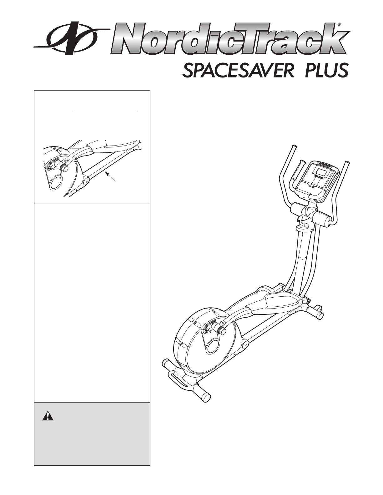
Model No. 30850.0
Serial No.
Write the serial number in the
space above for reference.
Serial Number
Decal
QUESTIONS?
If you have questions, or if parts
are damaged or missing, PLEASE
CONTACT OUR CUSTOMER
SERVICE DEPARTMENT
DIRECTLY.
CALL TOLL-FREE:
1-888-936-4266
Mon.–Fri., 8:00 until 17:00 ET
(excluding holidays)
USERʼS MANUAL
OR E-MAIL US:
customerservice@iconcanada.ca
CAUTION
Read all precautions and instructions in this manual before using
this equipment. Keep this manual
for future reference.
www.nordictrack.com
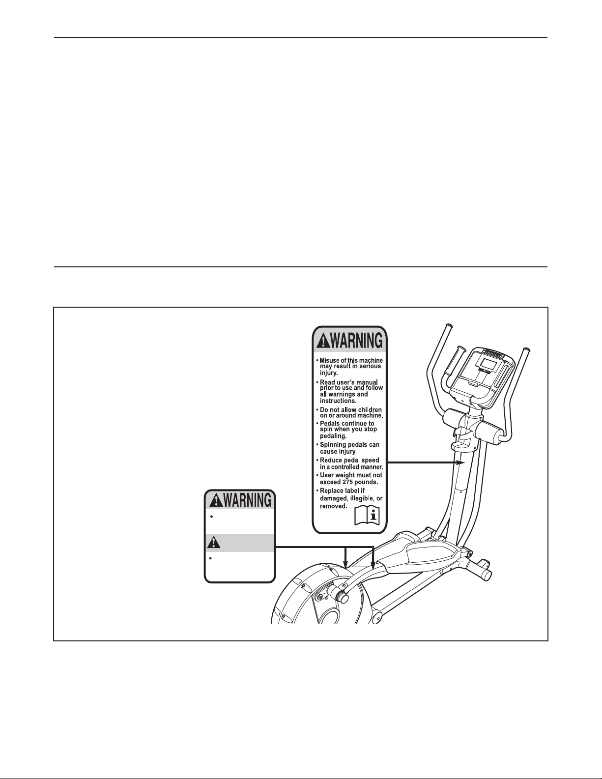
TABLE OF CONTENTS
Keep hands and
fingers clear of
this area.
AATTENTIONTTENTION
Gardez vos mains
et vos doigts
ÈloignÈs de cet
endroit.
ARNING DECAL PLACEMENT . . . . . . . . . . . . . . . . . . . . . . . . . . . . . . . . . . . . . . . . . . . . . . . . . . . . . . . . . . . . . .2
W
IMPORTANT PRECAUTIONS . . . . . . . . . . . . . . . . . . . . . . . . . . . . . . . . . . . . . . . . . . . . . . . . . . . . . . . . . . . . . . . .3
BEFORE YOU BEGIN . . . . . . . . . . . . . . . . . . . . . . . . . . . . . . . . . . . . . . . . . . . . . . . . . . . . . . . . . . . . . . . . . . . . . .4
ASSEMBLY . . . . . . . . . . . . . . . . . . . . . . . . . . . . . . . . . . . . . . . . . . . . . . . . . . . . . . . . . . . . . . . . . . . . . . . . . . . . . . .5
HOW TO USE THE ELLIPTICAL EXERCISER . . . . . . . . . . . . . . . . . . . . . . . . . . . . . . . . . . . . . . . . . . . . . . . . . .13
AINTENANCE AND TROUBLESHOOTING . . . . . . . . . . . . . . . . . . . . . . . . . . . . . . . . . . . . . . . . . . . . . . . . . . .21
M
EXERCISE GUIDELINES . . . . . . . . . . . . . . . . . . . . . . . . . . . . . . . . . . . . . . . . . . . . . . . . . . . . . . . . . . . . . . . . . . .22
PART LIST . . . . . . . . . . . . . . . . . . . . . . . . . . . . . . . . . . . . . . . . . . . . . . . . . . . . . . . . . . . . . . . . . . . . . . . . . . . . . .24
EXPLODED DRAWING . . . . . . . . . . . . . . . . . . . . . . . . . . . . . . . . . . . . . . . . . . . . . . . . . . . . . . . . . . . . . . . . . . . .26
ORDERING REPLACEMENT PARTS . . . . . . . . . . . . . . . . . . . . . . . . . . . . . . . . . . . . . . . . . . . . . . . . . .Back Cover
LIMITED WARRANTY . . . . . . . . . . . . . . . . . . . . . . . . . . . . . . . . . . . . . . . . . . . . . . . . . . . . . . . . . . . . . .Back Cover
WARNING DECAL PLACEMENT
This drawing shows the location(s) of the
warning decal(s). If a decal is missing or
illegible, see the front cover of this manual and request a free replacement decal.
Apply the decal in the location shown.
Note: The decal(s) may not be shown at
actual size.
NordicTrack is a registered trademark of ICON IP, Inc.
2

IMPORTANT PRECAUTIONS
WARNING: To reduce the risk of serious injury, read all important precautions and
instructions in this manual and all warnings on your elliptical exerciser before using your elliptical
exerciser. ICON assumes no responsibility for personal injury or property damage sustained by or
hrough the use of this product.
t
1. Before beginning any exercise program,
consult your physician. This is especially
important for persons over the age of 35 or
persons with pre-existing health problems.
2. It is the responsibility of the owner to ensure
that all users of the elliptical exerciser are
adequately informed of all precautions.
3. Your elliptical exerciser is intended for home
use only. Do not use your elliptical exerciser
in a commercial, rental, or institutional setting.
4. Keep your elliptical exerciser indoors, away
from moisture and dust. Place your elliptical
exerciser on a level surface, with a mat
beneath it to protect the floor or carpet.
Make sure that there is enough clearance
around your elliptical exerciser to mount,
dismount, and use it.
5. Inspect and properly tighten all parts regularly. Replace any worn parts immediately.
6. Keep children under age 12 and pets away
from your elliptical exerciser at all times.
8. Wear appropriate exercise clothes when
exercising; do not wear loose clothes that
could become caught on your elliptical exerciser. Always wear athletic shoes for foot
protection.
9. Hold the handgrip pulse sensor or the upper
body arms when mounting, dismounting, or
using your elliptical exerciser.
10. Keep your back straight while using your
elliptical exerciser; do not arch your back.
11. The pulse sensor is not a medical device.
Various factors, including the userʼs movement, may affect the accuracy of heart rate
readings. The pulse sensor is intended only
as an exercise aid in determining heart rate
trends in general.
12. When you stop exercising, allow the pedals
to slowly come to a stop.
13. Over exercising may result in serious injury
or death. If you feel faint or if you experience
pain while exercising, stop immediately and
cool down.
7. Your elliptical exerciser should not be used
by persons weighing more than 275 lbs.
(125 kg).
14. Use your elliptical exerciser only as
described in this manual.
3
BEFORE YOU BEGIN
Thank you for purchasing the revolutionary
ordicTrack
N
The SPACESAVER PLUS elliptical exerciser provides
a wide array of features designed to make your workouts at home more effective and enjoyable—and when
youʼre not exercising, the unique elliptical exerciser
can be folded out of the way.
For your benefit, read this manual carefully before
you use the elliptical exerciser. If you have ques-
®
PACESAVER PLUS elliptical exerciser.
S
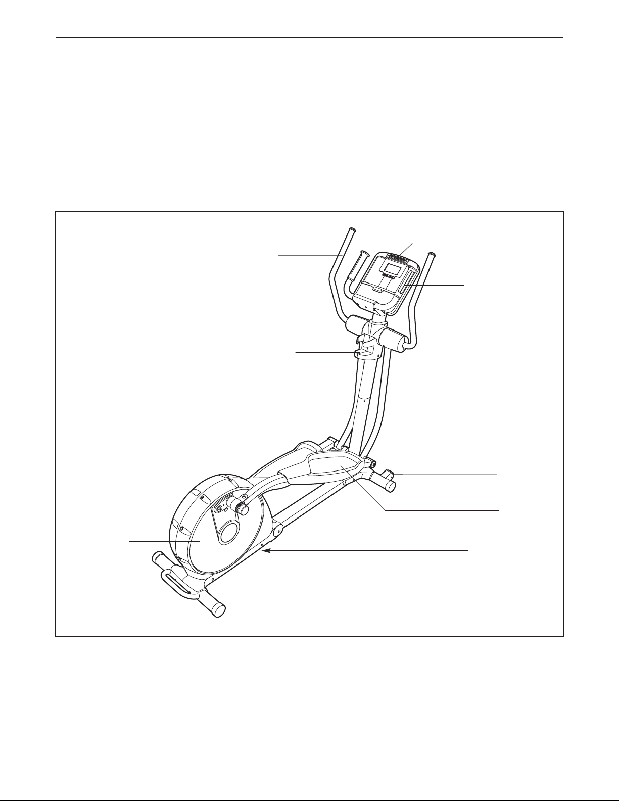
Upper Body Arm
Water Bottle Holder*
tions after reading this manual, please see the front
over of this manual. To help us assist you, note the
c
product model number and serial number before contacting us. The model number and the location of the
serial number decal are shown on the front cover of
this manual.
Before reading further, please familiarize yourself with
the parts that are labeled in the drawing below.
Fan
Console
Pulse Sensor
Pedal Disc
Handle
Wheel
Pedal
Latch Button
*No water bottle is included
4
ASSEMBLY
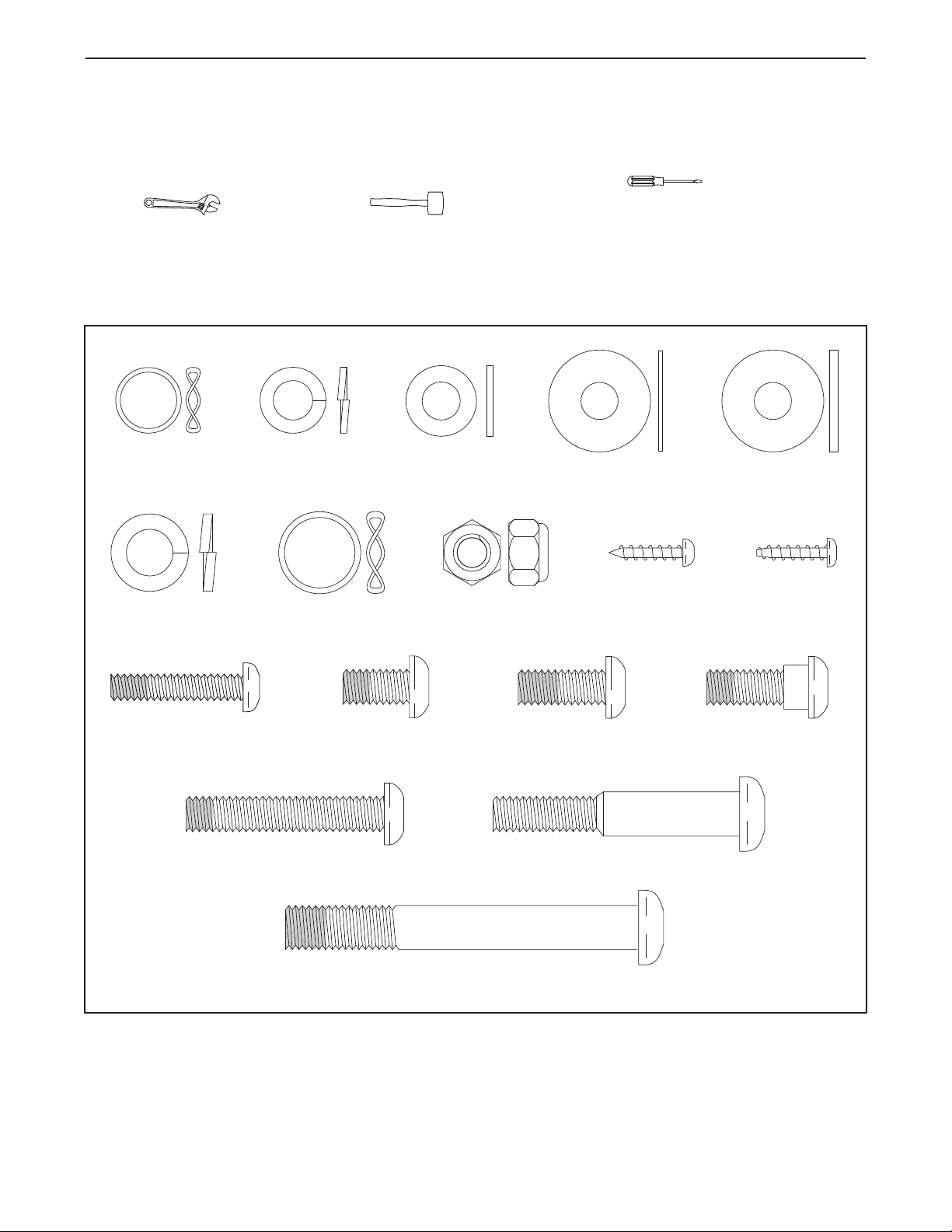
M8 x 23mm
Washer (31)–10
M8 Split
Washer (97)–16
M4 x 16mm
Round Head
Screw (92)–23
M8 Washer
(106)–2
Wave Washer
(80)–2
M10 Split
Washer (99)–4
M10 x 80mm Patch Screw (93)–4
Large Wave
Washer (89)–2
M8 x 23mm
Thin Washer
(96)–2
M4 x 16mm
Blunt Screw
(33)–5
M8 Nylon
Locknut (94)–2
M8 x 45mm Patch Screw (90)–6 M10 x 58mm Shoulder Bolt (104)–2
M8 x 14mm Patch
Screw (84)–6
M8 x 19mm Patch
Screw (86)–6
M8 x 23mm Shoulder
Patch Screw (105)–2
M6 x 32mm Patch
Screw (113)–4
Assembly requires two persons. Place all parts of the elliptical exerciser in a cleared area and remove the
packing materials. Do not dispose of the packing materials until assembly is completed.
Assembly requires the included tools and your own Phillips screwdriver , adjustable
wrench , and rubber mallet .
As you assemble the elliptical exerciser, use the drawings below to identify small parts. The number in parentheses below each drawing is the key number of the part, from the PART LIST near the end of this manual. The
number following the parentheses is the quantity needed for assembly. Note: Some small parts may have
been preassembled. If a part is not in the hardware kit, check to see if it has been preassembled.
5
1.
To make assembly easier, read the
information on page 5 before you begin
ssembling the elliptical exerciser.
a
ee HOW TO FOLD AND UNFOLD THE
S
ELLIPTICAL EXERCISER on page 13 and
unfold the elliptical exerciser.
1
99
93
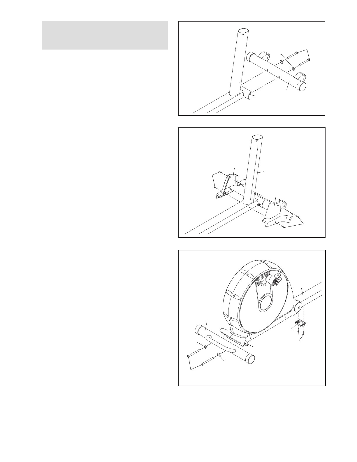
While another person lifts the front of the
Frame (1), attach the Front Stabilizer (4) to the
Frame with two M10 x 80mm Patch Screws (93)
and two M10 Split Washers (99).
2. Attach the Left and Right Frame Covers (36,
37) around the Frame (1) with four M4 x 16mm
Round Head Screws (92).
3. With the help of another person, carefully tip
the elliptical exerciser onto its side. Attach the
Center Foot (40) to the Frame (1) with two
M4 x 16mm Blunt Screws (33). Then, return the
elliptical exerciser to the upright position.
1
2
36
92
3
1
4
37
92
1
Orient the Rear Stabilizer (3) as shown. While
another person lifts the Folding Frame (2),
attach the Rear Stabilizer to the Folding Frame
with two M10 x 80mm Patch Screws (93) and
two M10 Split Washers (99).
3
40
99
2
99
93
33
6
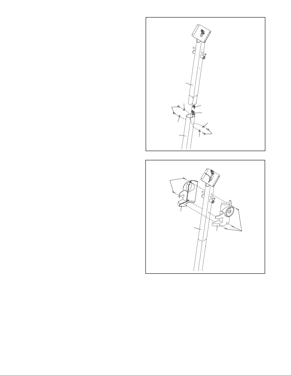
4. Tip: Be careful not to pinch the Wire
Harnesses (64, 65) during this step.
hile another person holds the Upright (10)
W
near the Frame (1), connect the Upper Wire
Harness (65) to the Lower Wire Harness (64).
Then, insert the Upright (10) into the Frame (1).
Attach the Upright with four M8 x 19mm Patch
Screws (86) and four M8 Split Washers (97).
Do not tighten the Patch Screws yet.
4
10
Avoid pinching the
Wire Harnesses (64, 65)
during this step
5. Orient the Left and Right Upright Covers (19,
20) as shown. Attach the Upright Covers
around the Upright (10) with five M4 x 16mm
Round Head Screws (92).
97
86
97
1
5
92
19
10
97
65
64
97
86
20
92
7
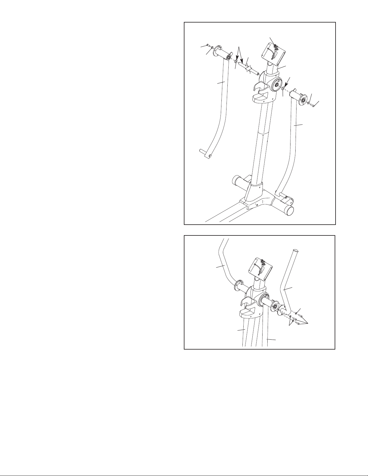
6. Tip: Be careful not to damage the Upper
Wire Harness (65).
pply a generous amount of the included grease
A
to the Upper Body Axle (71). Insert the Upper
ody Axle into the Upright (10).
B
Apply a small amount of grease to a Wave
Washer (80). Slide the Wave Washer onto the
left end of the Upper Body Axle (71).
Identify the Left Upper Body Leg (24), which is
marked with an “L” sticker, and orient it as
shown. Slide the Left Upper Body Leg onto the
left side of the Upper Body Axle (71).
Attach the Left Upper Body Leg (24) to the Upper
Body Axle (71) with an M8 x 19mm Patch Screw
(86) and an M8 x 23mm Washer (31).
Repeat this step for the Right Upper Body
Leg (72).
6
86
31
2
Grease
71
80
4
65
80
10
Grease
31
86
72
7. Attach the Right Upper Body Arm (23) to the
Right Upper Body Leg (72) with three M8 x
14mm Patch Screws (84) and three M8 Split
Washers (97).
Attach the Left Upper Body Arm (22) in the
same way.
7
22
23
97
84
24
97
72
8
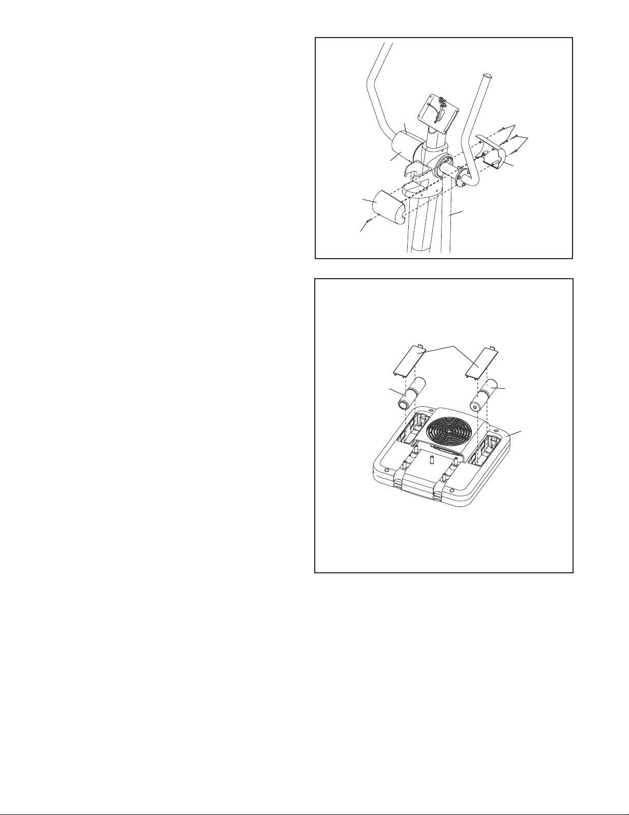
. Hold the Right Rear Upper Body Cover (28) and
8
the Right Front Upper Body Cover (29) around
the Right Upper Body Leg (72). Attach the
Upper Body Covers with five M4 x 16mm Round
ead Screws (92).
H
ttach the Left Rear Upper Body Cover (26)
A
and the Left Front Upper Body Cover (27) in
the same way.
8
27
92
92
9. The Console (11) can be operated with four
1.5V “D” batteries (not included); alkaline batteries are recommended. IMPORTANT: If the
elliptical exerciser has been exposed to cold
temperatures, allow it to warm to room temperature before inserting batteries into the
Console. If you do not do this, the console
displays or other electronic components
may become damaged. Press the tabs on the
battery covers and remove the battery covers.
Next, insert four batteries into the Console;
make sure that the batteries are oriented as
shown by the diagrams inside the Console.
Then, reattach the battery covers.
9
26
28
92
Batteries
29
72
Battery
Covers
Batteries
11
The Console (11) can also be operated with an
optional power supply (not included). To pur-
chase a power supply, see the front cover of
this manual. To avoid damaging the console,
use only a manufacturer-supplied power
supply. Plug one end of the power supply into
the jack on the Console; plug the other end into
an outlet installed in accordance with all local
codes and ordinances.
9
 Loading...