

NordicTrack 307070 Owner's Manual
Model No. 30707.0
www.proform.com
Visit our website at
www.nordictrack.com
Visit our website at
www.healthrider.com
Visit our website at
Serial No.
Serial Number
Decal
QUESTIONS?
As a manufacturer, we are committed to providing complete
customer satisfaction. If you
have questions, or if there are
missing parts, please call:
1-888-936-4266
Mon.–Fri. 8h00 until 17h00 EST
(excluding holidays).
BIKE EXERCISER
User’s Manual
CAUTION
Read all precautions and instructions in this manual before using
this equipment. Keep this manual
for future reference.

TABLE OF CONTENTS
IMPORTANT PRECAUTIONS . . . . . . . . . . . . . . . . . . . . . . . . . . . . . . . . . . . . . . . . . . . . . . . . . . . . . . . . . . . . . . . .2
EFORE YOU BEGIN . . . . . . . . . . . . . . . . . . . . . . . . . . . . . . . . . . . . . . . . . . . . . . . . . . . . . . . . . . . . . . . . . . . . . .3
B
ASSEMBLY . . . . . . . . . . . . . . . . . . . . . . . . . . . . . . . . . . . . . . . . . . . . . . . . . . . . . . . . . . . . . . . . . . . . . . . . . . . . . . .4
HOW TO OPERATE THE EXERCISE CYCLE . . . . . . . . . . . . . . . . . . . . . . . . . . . . . . . . . . . . . . . . . . . . . . . . . . . .9
MAINTENANCE AND TROUBLESHOOTING . . . . . . . . . . . . . . . . . . . . . . . . . . . . . . . . . . . . . . . . . . . . . . . . . . .16
CONDITIONING GUIDELINES . . . . . . . . . . . . . . . . . . . . . . . . . . . . . . . . . . . . . . . . . . . . . . . . . . . . . . . . . . . . . . .17
PART LIST . . . . . . . . . . . . . . . . . . . . . . . . . . . . . . . . . . . . . . . . . . . . . . . . . . . . . . . . . . . . . . . . . . . . . . . . . . . . . .21
EXPLODED DRAWING . . . . . . . . . . . . . . . . . . . . . . . . . . . . . . . . . . . . . . . . . . . . . . . . . . . . . . . . . . . . . . . . . . . .22
ORDERING REPLACEMENT PARTS . . . . . . . . . . . . . . . . . . . . . . . . . . . . . . . . . . . . . . . . . . . . . . . . . .Back Cover
LIMITED WARRANTY . . . . . . . . . . . . . . . . . . . . . . . . . . . . . . . . . . . . . . . . . . . . . . . . . . . . . . . . . . . . . .Back Cover
IMPORTANT PRECAUTIONS
WARNING:
tions before using the exercise cycle.
1. Read all instructions in this manual and all
warnings on the exercise cycle before using
the exercise cycle. Use the exercise cycle
only as described in this manual.
2. It is the responsibility of the owner to ensure
that all users of the exercise cycle are adequately informed of all precautions.
3. The exercise cycle is intended for home use
only. Do not use the exercise cycle in
a commercial, rental, or institutional setting.
4. Keep the exercise cycle indoors, away from
moisture and dust. Place the exercise cycle
on a level surface, with a mat beneath it to
protect the floor or carpet. Make sure that
there is enough clearance around the exercise cycle to mount, dismount, and use the
exercise cycle.
5.
Inspect and properly tighten all parts regularly. Replace any worn parts immediately.
6. Keep children under the age of 12 and pets
away from the exercise cycle at all times.
To reduce the risk of serious injury, read the following important precau-
7. Wear appropriate clothes when exercising;
do not wear loose clothes that could become
caught on the exercise cycle. Always wear
athletic shoes for foot protection.
8. The exercise cycle should not be used by
persons weighing more than 300 lbs.
(136 kg).
9. The pulse sensor is not a medical device.
Various factors, including the user's movement, may affect the accuracy of heart rate
readings. The pulse sensor is intended only
as an exercise aid in determining heart rate
trends in general.
10.Always keep your back straight when using
the exercise cycle; do not arch your back.
11.If you feel pain or dizziness while exercising,
stop immediately and cool down.
12.The warning decal shown on page 3 has been
placed on the exercise cycle. If the decal is
missing or illegible, please call the toll-free
telephone number on the front cover of this
manual and order a free replacement decal.
Apply the decal in the location shown.
WARNING:Before beginning this or any exercise program, consult your physician. This
is especially important for persons over the age of 35 or persons with pre-existing health problems.
Read all instructions before using. ICON assumes no responsibility for personal injury or property
damage sustained by or through the use of this product.
2
REVISIONS
DRA WINGS PREVIOUS TO LAST REV . DA TE ARE OBSOLETE
DA TE
REV ECN DESCRIPTION OF CHANGE
Un mauvais usage de
ce produit peut causer
de sérieuses blessures.
Lisez le livret d'instructions et suivre les conseils de sécurité
importants.
Remplacer l'étiquette
si celle-ci est endommagée,illisible ou enlevée.
L
e poids de l'utilisateur
ne devrait pas excéder
136kg
Gardez les enfants
éloignés en tout temps.
Replace label if
damaged,illegible,
or removed.
User weight must not
exceed 300 pounds.
Do not allow children
on or around machine.
Read user's manual
prior to use and follow
all warnings and
instructions.
M
isuse of this machine
may result in serious
injury.
ATTENTION
253398
BEFORE YOU BEGIN
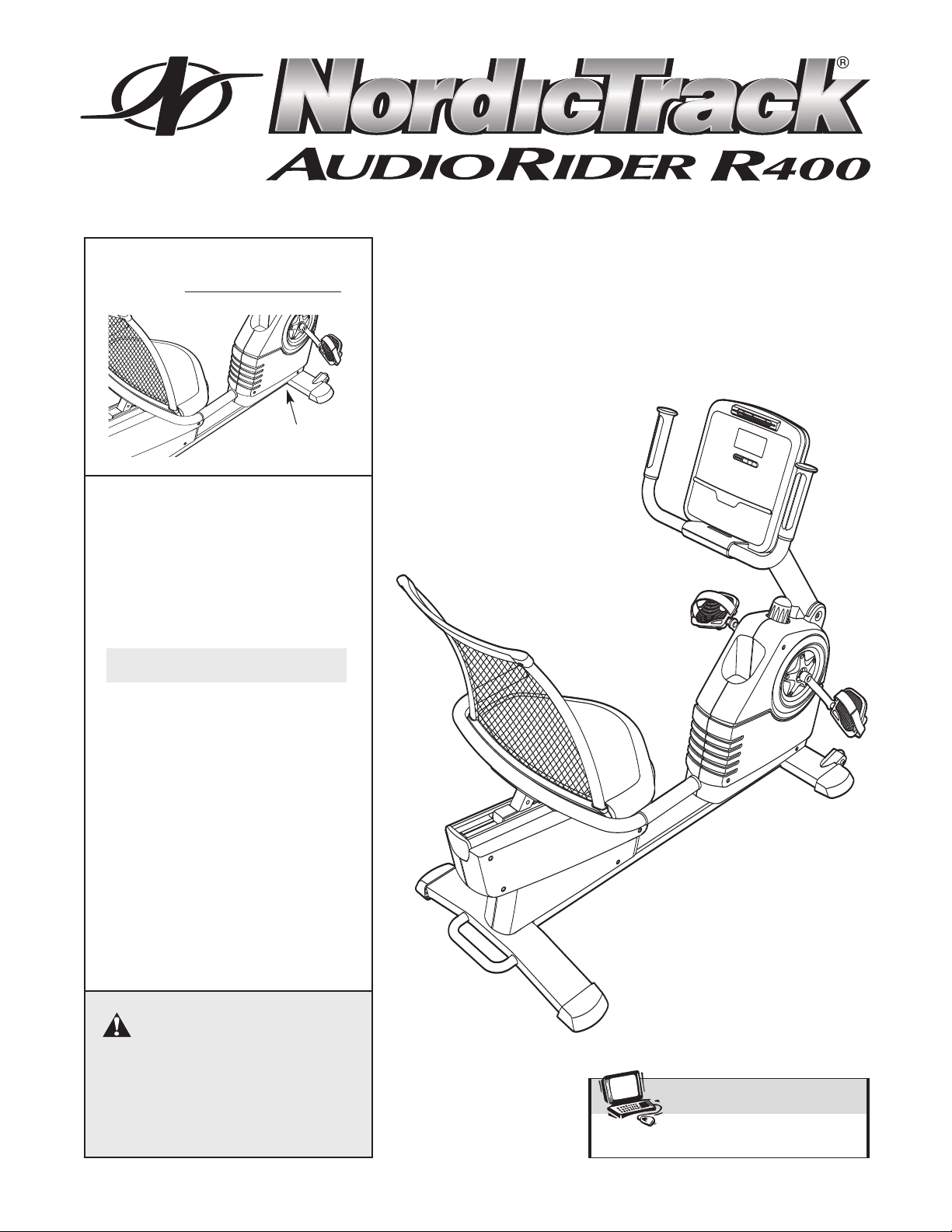
Congratulations for selecting the new NordicTrack
UDIORIDER R400 exercise cycle. Cycling is one of
A
he most effective exercises for increasing cardiovas-
t
®
cular fitness, building endurance, and toning the entire
body. The AUDIORIDER R400 exercise cycle offers
an impressive array of features to let you enjoy this
healthful exercise in the convenience and privacy of
your home.
For your benefit, read this manual carefully before
you use the exercise cycle. If you have questions
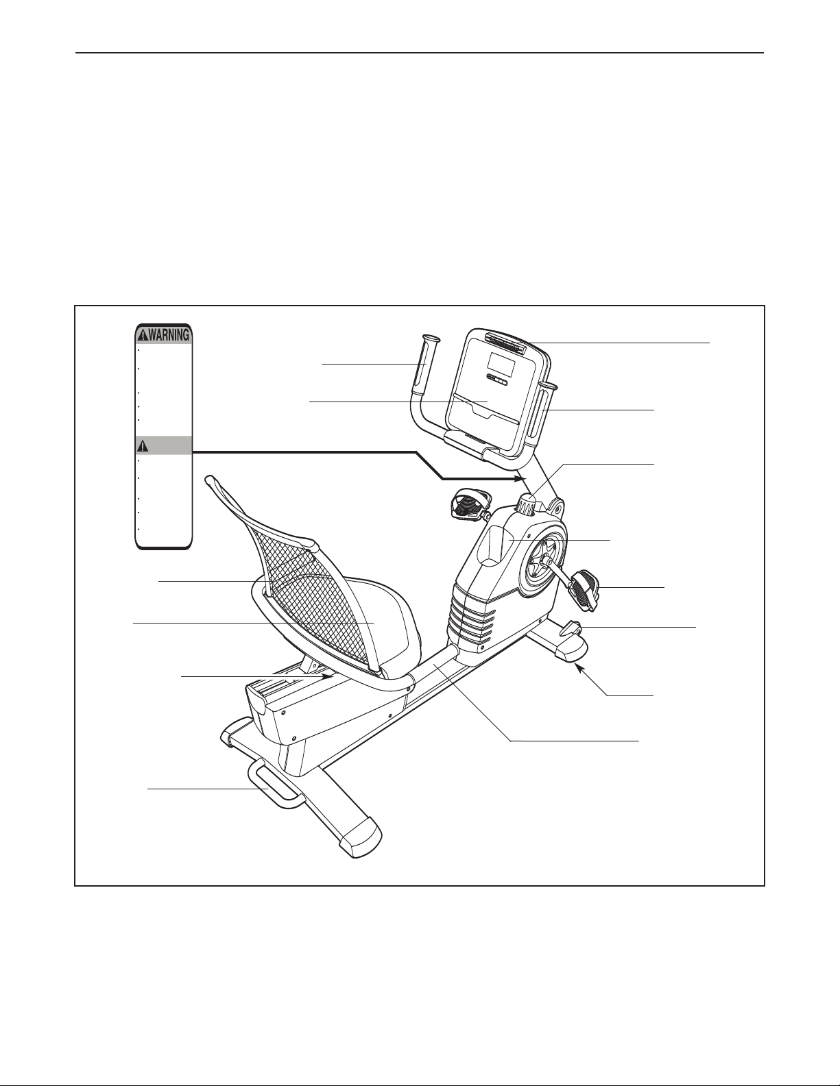
Handlebar
Console
after reading this manual, please see the front cover
f this manual. To help us assist you, note the product
o
odel number and serial number before contacting
m
us. The model number is 30707.0. The serial number
can be found on a decal attached to the exercise cycle
(see the front cover of this manual).
Before reading further, please familiarize yourself with
the parts that are labeled in the drawing below.
Fan
Pulse Sensor
Upright Knob
Backrest
Seat
Seat Handle
Handle
NordicT
rack is a registered trademark of ICON IP
3
Water Bottle Holder*
Pedal/Strap
Wheel
Leveling Foot
Seat Handlebar
*No water bottle is included
, Inc.
M8 Split
Washer (55)–14
M4 x 16mm
Round Head
Screw (80)–6
M6 Washer
(75)–10
M6 x 16mm Button
Screw (81)–4
M6 x 28mm Button
Screw (67)–6
M10 x 63mm Bolt Set (62)–1
M8 x 19mm Button
Screw (77)–4
M8 x 16mm Button
Screw (54)–6
M8 x 50mm Button
Screw (52)–4
M4 x 12mm
Screw (85)–1
M6 x 30mm Button
Screw (37)–4
ASSEMBLY
ssembly requires two persons. Place all parts of the exercise cycle in a cleared area and remove the packing
A
materials. Do not dispose of the packing materials until assembly is completed.
Assembly requires the included tools and your own adjustable wrench and Phillips screw-
river .
d
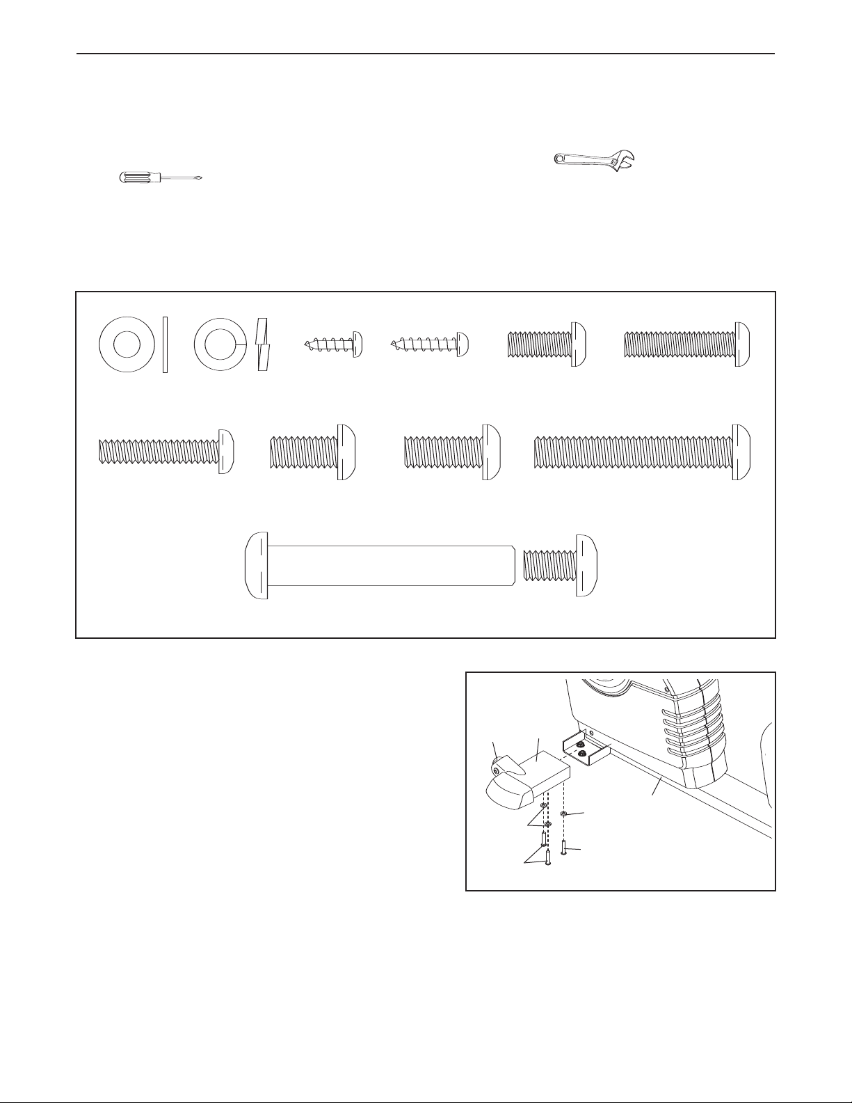
Use the part drawings below to identify the small parts used in assembly. The number in parentheses below
each drawing is the key number of the part, from the PART LIST on page 21. The second number is the quantity
needed for assembly.
bag, check to see if it has been pre-attached.
Note: Some small parts may have been pre-attached. If a part is not in the parts
1. Orient the Left Front Stabilizer (15) with the Wheel (17)
positioned as shown. Attach the Left Front Stabilizer to
the left side of the Frame (1) with three M8 x 16mm
Button Screws (54) and three M8 Split Washers (55).
Attach the Right Front Stabilizer (not shown) to the
right side of the Frame (1) in the same way.
1
17
55
54
4
15
55
54
1
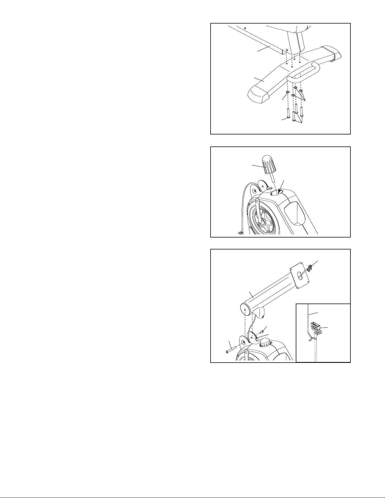
2. While another person lifts the rear of the Frame (1),
attach the Rear Stabilizer (16) to the Frame with four
8 x 50mm Button Screws (52) and four M8 Split
M
Washers (55).
2
1
16
3. Tighten the Upright Knob (7) into the Frame (1).
4. Have another person hold the Upright (2) near the
front of the Frame (1). Locate the wire tie (see the
inset drawing) in the Upright. Tie the lower end of the
wire tie to the Main Wire Harness (43). Next, pull the
upper end of the wire tie upward out of the top of the
Upright. Then, untie and discard the wire tie.
3
4
Avoid pinching
and damaging
the wires
55
52
7
1
2
55
52
43
Attach the Upright (2) to the Frame (1) with an M10 x
63mm Bolt Set (62). Be careful to avoid pinching the
Main Wire Harness (43).
5
62
62
Wire Tie
43
1
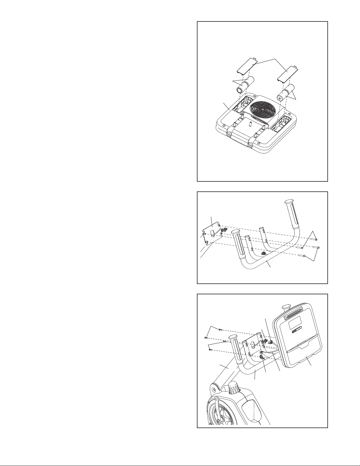
5. The Console (4) requires four “D” batteries (not included); alkaline batteries are recommended. IMPOR-
ANT: If the exercise cycle has been exposed to
T
cold temperatures, allow it to warm to room tem-
erature before inserting batteries into the
p
Console. If you do not do this, the console displays or other electronic components may become
damaged. Remove the battery covers from the back
of the Console. Next, insert four batteries into the battery compartments; make sure that the batteries are
oriented as shown by the diagrams inside the battery compartments.
ers.
Note: The Console (4) can be operated with an optional power supply instead of batteries.
power supply, call the toll-free telephone number
on the front cover of this manual. Plug one end of
the power supply into the jack at the front of the exercise cycle. Plug the other end of the power supply into
an appropriate outlet that is properly installed in accordance with all local codes and ordinances.
Then, reattach the battery cov-
To purchase a
5
Batteries
Battery
overs
C
4
Batteries
6. Attach the Handlebar (39) to the Upright (2) with four
M6 x 30mm Button Screws (37).
7. While another person holds the Console (4) near the
Handlebar (39), connect the wire harness on the
Console to the Main Wire Harness (43). Next, connect
the pulse wire on the Console to the Pulse Wire (51) in
the Handlebar (39). Note: The remaining wire on the
Console is used during the manufacturing process;
disregard this wire.
Insert the excess wiring downward into the Upright (2).
Attach the Console (4) to the Handlebar (39) and the
Upright with four M4 x
(80).
Be careful to avoid pinching the W
16mm Round Head Screws
ires (43, 51).
6
7
80
80
2
37
37
39
ire
W
Harness
43
2
Pulse
51
39
Wire
4
Avoid pinching
ires (43, 51)
W
the
during this step
6
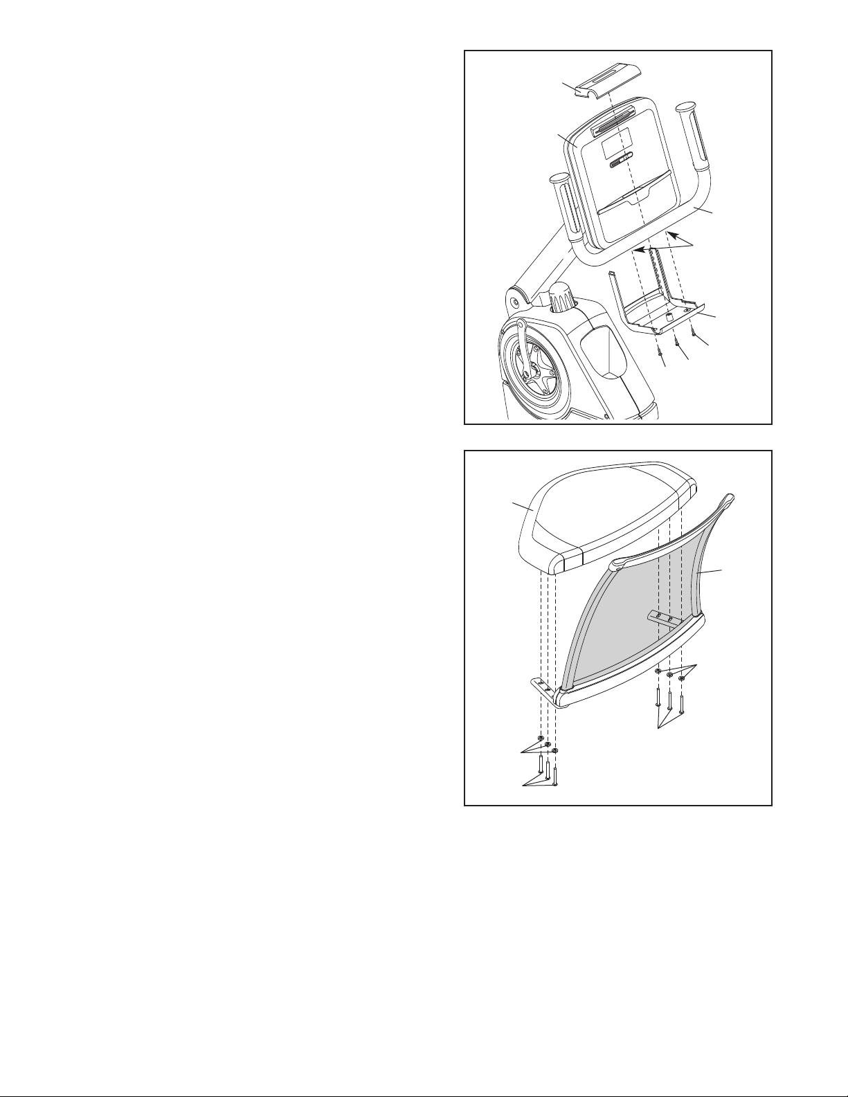
8. Slide the Bottom Handlebar Cover (25) into the slots in
he bottom of the Console (4). Attach the Bottom
t
Handlebar Cover to the Handlebar (39) and the Top
andlebar Cover (18) with two M4 x 16mm Round
H
Head Screws (80) and one M4 x 12mm Screw (85).
8
18
4
39
Slots
25
80
85
80
9. Attach the Seat (9) to the Backrest (8) with six M6 x
28mm Button Screws (67) and six M6 Washers (75).
Start all six Button Screws before tightening any of
them.
9
9
8
75
67
75
67
7
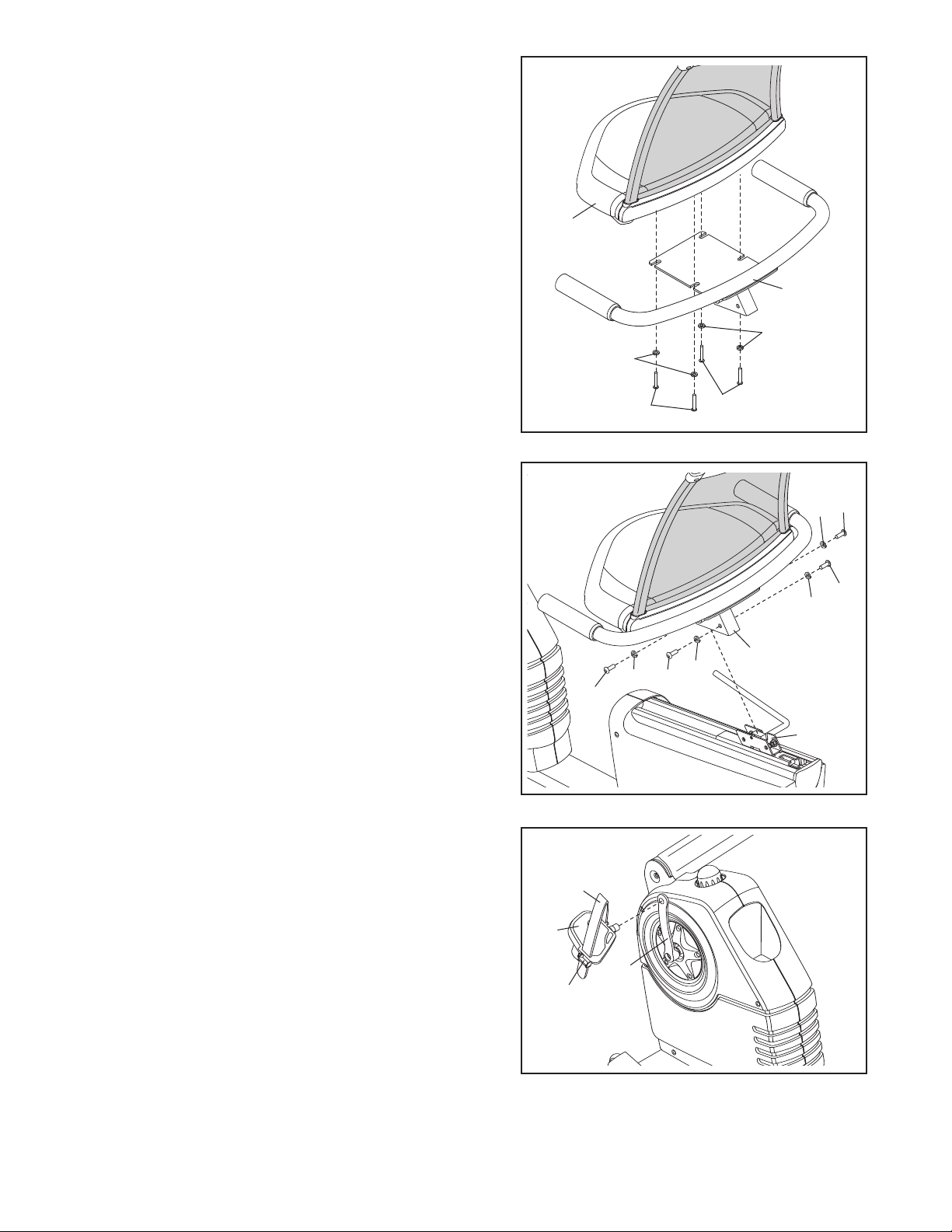
10. Attach the Seat (9) to the Seat Bracket (11) with four
6 x 16mm Button Screws (81) and four M6 Washers
M
(75). Start all four Button Screws before tightening
ny of them.
a
0
1
9
11
75
75
11. Attach the Seat Bracket (11) to the Seat Carriage (41)
with four M8 x 19mm Button Screws (77) and four M8
Split Washers (55). Start all four Button Screws
before tightening any of them.
12.Identify the Left Pedal (22), which is marked with an
“L.” Using an adjustable wrench, firmly tighten the
Left Pedal
Arm (24). Tighten the Right Pedal (not shown)
wise
Tighten both Pedals as firmly as possible. After
using the exercise cycle for one week, retighten
the Pedals.
Adjust the strap on the Left Pedal (22) to the desired
position, and insert the end of the strap into the latch
on the Left Pedal. Adjust the strap on the Right
Pedal (not shown) in the same way.
counterclockwise
into the Left Crank
clock-
into the Right Crank Arm (not shown). Important:
11
12
22
Latch
Strap
77
24
55
81
77
55
81
11
41
55
55
77
77
13.Make sure that all parts are properly tightened before you use the exercise cycle. Note: After assembly is
completed, some extra parts may be left over
. Place a mat beneath the exercise cycle to protect the floor.
8
 Loading...