

Page 1
Page 2

RM-84/99
Nokia Customer Care Service Tools and Service Concepts
(This page left intentionally blank.)
Page 1–2 Company Confidential Issue 1
Copyright ©2005 Nokia. All Rights Reserved.
Page 3

RM-84/99
Service Tools and Service Concepts Nokia Customer Care
Table of Contents
Service tools......................................................................................................................................................................................1–5
CA-31D...........................................................................................................................................................................................1–5
CA-35S......................................................................................................................................................................................1–0
CU-4...........................................................................................................................................................................................1–0
DKU-2........................................................................................................................................................................................1–0
FLS-4S............................................................................................................................................................................................1–7
FPS-10.......................................................................................................................................................................................1–0
FS-14.........................................................................................................................................................................................1–0
JBT-9.........................................................................................................................................................................................1–0
MJ-70.........................................................................................................................................................................................1–0
PCS-1.........................................................................................................................................................................................1–0
PKD-1........................................................................................................................................................................................1–0
RF shield box...............................................................................................................................................................................1–9
RJ-104.......................................................................................................................................................................................1–0
RJ-94.........................................................................................................................................................................................1–0
SA-95........................................................................................................................................................................................1–0
SPI-1..........................................................................................................................................................................................1–0
SPS-1...........................................................................................................................................................................................1–10
SRT-6.........................................................................................................................................................................................1–0
SS-15...........................................................................................................................................................................................1–11
SS-34.........................................................................................................................................................................................1–0
SS-46.........................................................................................................................................................................................1–0
SS-51...........................................................................................................................................................................................1–11
SS-62.........................................................................................................................................................................................1–0
SS-68...........................................................................................................................................................................................1–12
ST-37.........................................................................................................................................................................................1–0
SX-4...........................................................................................................................................................................................1–0
XCS-1...........................................................................................................................................................................................1–13
XCS-4...........................................................................................................................................................................................1–13
XRS-6...........................................................................................................................................................................................1–13
Service concepts............................................................................................................................................................................1–14
Flash concept with FPS-10...................................................................................................................................................1–14
MJ-70 module jig concept....................................................................................................................................................1–15
POS (Point of Sale) flash concept.......................................................................................................................................1–16
Service concept for RF/BB testing and tuning...............................................................................................................1–17
CU-4 flash concept with FPS-10..........................................................................................................................................1–18
RF testing and BB testing/tuning......................................................................................................................................1–19
LAN connection flash concept.............................................................................................................................................1–20
List of Figures
Figure 1 Basic flash concept with FPS-10..............................................................................................................................1–14
Figure 2 MJ-70 module jig service concept...........................................................................................................................1–15
Figure 3 POS flash concept.........................................................................................................................................................1–16
Figure 4 Service concept for RF/BB testing and tuning....................................................................................................1–17
Figure 5 CU-4 flash concept with FPS-10...............................................................................................................................1–18
Figure 6 RF testing and BB testing/tuning...........................................................................................................................1–19
Figure 7 LAN connection flash concept..................................................................................................................................1–20
Issue 1 Company Confidential Page 1–3
Copyright ©2005 Nokia. All Rights Reserved.
Page 4

RM-84/99
Nokia Customer Care Service Tools and Service Concepts
(This page left intentionally blank.)
Page 1–4 Company Confidential Issue 1
Copyright ©2005 Nokia. All Rights Reserved.
Page 5
RM-84/99
Service Tools and Service Concepts Nokia Customer Care
Service tools
List of Service Tools
The table below gives a short overview of service tools that can be used for testing, error analysis and repair
of product , refer to various concepts.
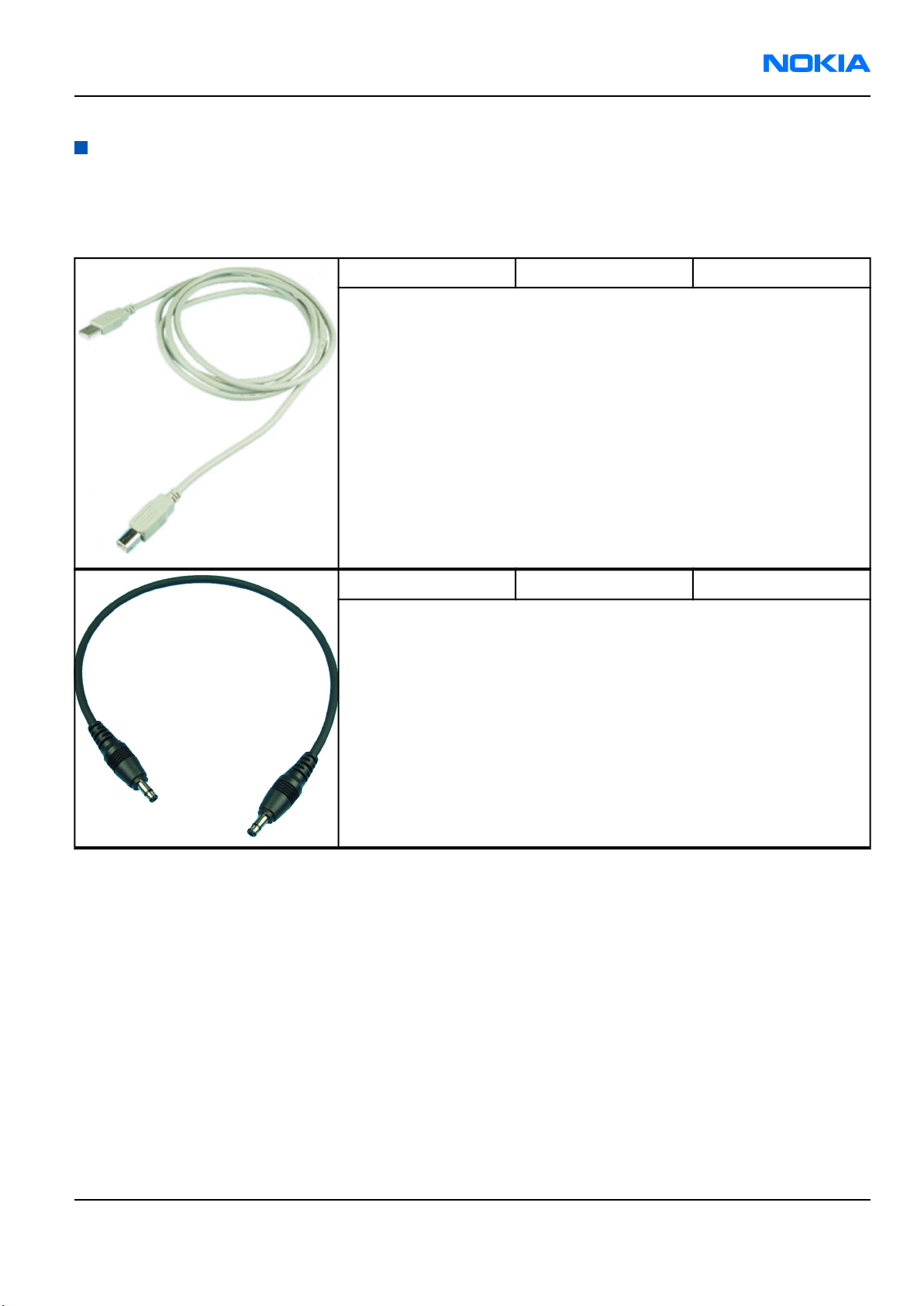
CA-31D USB cable
The CA-31D USB cable is used to connect FPS-10 or FPS-11 to a PC. It is
included in the FPS-10 and FPS-11 sales packages.
CA-35S Power cable
Power cable for connecting e.g. the FPS-10 prommer box to the POS flash
adapter.
Issue 1 Company Confidential Page 1–5
Copyright ©2005 Nokia. All Rights Reserved.
Page 6
RM-84/99
Nokia Customer Care Service Tools and Service Concepts
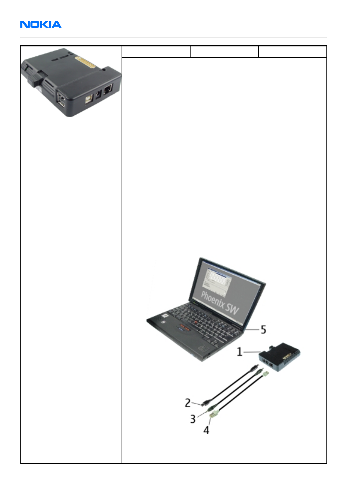
CU-4 Control unit
CU-4 is a general service tool used with a module jig and/or a flash
adapter.
CU-4 requires an external 12 V power supply.
The unit has the following features:
• software controlled via USB
• EM calibration function
• Forwards FBUS/Flashbus traffic to/from terminal
• Forwards USB traffic to/from terminal
• software controlled BSI values
• regulated VBATT voltage
• 2 x USB2.0 connector (Hub)
• FBUS and USB connections supported
When using CU-4, note the special order of connecting cables and other
service equipment:
Instructions
1 Connect a service tool (jig, flash adapter) to CU-4.
2 Connect CU-4 to your PC with a USB cable.
3 Connect supply voltage (12 V)
4 Connect an FBUS cable (if necessary).
5 Start Phoenix service software.
Note: Phoenix enables CU-4 regulators via USB when it starts.
Reconnecting the power supply requires a restart of Phoenix.
Page 1–6 Company Confidential Issue 1
Copyright ©2005 Nokia. All Rights Reserved.
Page 7

RM-84/99
Service Tools and Service Concepts Nokia Customer Care
DKU-2 USB connectivity cable
USB to Pop-PortTM connector cable.
FLS-4S Flash device
FLS-4S is a dongle and flash device incorporated into one package,
developed specifically for POS use.
FPS-10 Flash prommer
FPS-10 interfaces with:
• PC
• Control unit
• Flash adapter
• Smart card
FPS-10 flash prommer features:
• Flash functionality for BB5 and DCT-4 terminals
• Smart Card reader for SX-2 or SX-4
• USB traffic forwarding
• USB to FBUS/Flashbus conversion
• LAN to FBUS/Flashbus and USB conversion
• Vusb output switchable by PC command
FPS-10 sales package includes:
• FPS-10 prommer
• Power Supply with 5 country specific cords
• USB cable
Issue 1 Company Confidential Page 1–7
Copyright ©2005 Nokia. All Rights Reserved.
Page 8

RM-84/99
Nokia Customer Care Service Tools and Service Concepts
FS-14 Flash adapter
Flash adapter FS-14 is used for phone testing and flashing.
FS-14 is used with the generic flash adapter base SS-60/62 and control
Unit CU-4 or interface adapter SS-46. When flashing or system testing
the phone, the adapter is attached to replace the phone own battery.
All functions (as well as the calibration voltages, current and the
protections for over voltages, over current and voltage polarity), are
performed by CU-4.
Flash adapter FS-14 main features:
• VBATT supply interface
• USB / FBUS multiplexed interface to the phone
• Supply voltage for light source
JBT-9 Bluetooth test and
interface box (sales
pack)
The JBT-9 test box is a generic device to perform Bluetooth bit error rate
testing and doing cordless FBUS connection via Bluetooth. An ACP-8x
charger is needed for BER testing and AXS-4 cable in case of cordless
testing interface usage.
• JBT-9 testbox, code 0770336
• Installation and warranty information, code 9360613
MJ-70 Module jig
Module jig MJ-70 is designed for engine testing. It can be used for
flashing and RF, battery and system testing.
Module jig MJ-70 main functions:
• CU-4 interface adapter to phone
• USB / FBUS multiplexed interface to phone
• UI Interface to phone
• STI and XTI test interface
• WCDMA and GSM RF-interface
All functions, except USB / FBUS multiplexing, are performed in CU-4. For
instance, adjusting calibration voltages and current, and all protections
for over current, over voltage and voltage polarity.
Page 1–8 Company Confidential Issue 1
Copyright ©2005 Nokia. All Rights Reserved.
Page 9

RM-84/99
Service Tools and Service Concepts Nokia Customer Care
PCS-1 Power cable
The PCS-1 power cable (DC) is used with a docking station, a module jig
or a control unit to supply a controlled operating voltage.
PKD-1 SW security device
SW security device is a piece of hardware enabling the use of the service
software when connected to the parallel (LPT) port of the PC.
Without the device, it is not possible to use the service software.
Printer or any such device can be connected to the PC through the device
if needed.
RF shield box
Because the WCDMA network disturbs the RX side testing of the WCDMA
phone and the Tx signal of the WCDMA phone can severely disturb the
WCDMA network, a shield box is needed in all testing, tuning and fault
finding which requires WCDMA RF signal.
The shield box is not an active device, it contains only passive filtering
components for RF attenuation.
RJ-104 BTHFM rework jig
RJ-104 is a rework jig used when servicing the BTHFM module. It is used
together with rework stencil ST-37.
RJ-94 Soldering jig
RJ-94 is a soldering jig used for soldering and as a rework jig for the
engine module.
Issue 1 Company Confidential Page 1–9
Copyright ©2005 Nokia. All Rights Reserved.
Page 10

RM-84/99
Nokia Customer Care Service Tools and Service Concepts
SA-95 RF coupler
SA-95 is an RF coupler for WCDMA and GSM RF testing. It is used together
with the product-specific flash adapter.
The following table shows attenuations from the antenna pads of the
mobile terminal to the SMA connectors of SA-95:
•
GSM900 TX Att. (dB) GSM900 RX Att. (dB)
880 MHz 2.9 925 MHz 3.5
897 MHz 2.9 942 MHz 4.7
915 MHz 3 960 MHz 6.6
GSM1800 TX Att. (dB) GSM1800 RX Att. (dB)
1710 MHz 6.4 1805 MHz 5.8
1748 MHz 6.3 1843 MHz 6.7
1785 MHz 6 1880 MHz 5.5
GSM1900 TX Att. (dB) GSM1900 RX Att. (dB)
1850 MHz 6.7 1930 MHz 5.4
1880 MHz 5.5 1960 MHz 5.7
1910 MHz 4.9 1990 MHz 5.9
WCDMA TX Att. (dB) WCDMA RX Att. (dB)
1920 MHz 6.6 2110 MHz 7
1950 MHz 6.3 2140 MHz 7.4
1980 MHz 6.1 2170 MHz 8.9
SPI-1 Soldering paste
injector
SPS-1 Soldering Paste
Spreader
Page 1–10 Company Confidential Issue 1
Copyright ©2005 Nokia. All Rights Reserved.
Page 11

RM-84/99
Service Tools and Service Concepts Nokia Customer Care
SRT-6 Opening tool
SS-15 Camera removal tool
The camera removal tool SS-15 is used to remove/attach the camera
module from/to the socket on the phone PWB.
SS-34 Flex opening tool
SS-46 Interface adapter
SS-46 acts as an interface adapter between the product-specific flash
adapter and FPS-10.
SS-51 Front camera removal
tool
The front camera removal tool SS-51 is used to remove/attach the front
camera module from/to the socket on the phone PWB.
Issue 1 Company Confidential Page 1–11
Copyright ©2005 Nokia. All Rights Reserved.
Page 12

RM-84/99
Nokia Customer Care Service Tools and Service Concepts
SS-62 Generic flash adapter
base for BB5
• generic base for flash adapters and couplers
• SS-62 equipped with a clip interlock system
• provides standardised interface towards Control Unit
• provides RF connection using galvanic connector or coupler
• multiplexing between USB and FBUS media, controlled by VUSB
SS-68 Antenna cover
opening tool
SS-68 is a tool for removing the antenna cover.
ST-37 BTHFM rework stencil
ST-37 stencil is used with RJ-104 BTHFM rework jig.
SX-4 Smart card
SX-4 is a BB5 security device used to protect critical features in tuning
and testing.
SX-4 is also needed together with FPS-10 when DCT-4 phones are flashed.
Page 1–12 Company Confidential Issue 1
Copyright ©2005 Nokia. All Rights Reserved.
Page 13

RM-84/99
Service Tools and Service Concepts Nokia Customer Care
XCS-1 Service cable
The XCS-1 service cable is used to connect FLS-4S to the POS flash adapter
for supplying a controlled operating voltage and data connection.
XCS-4 Modular cable
XCS-4 is a shielded (one specially shielded conductor) modular cable for
flashing and service purposes.
XRS-6 RF cable
The RF cable is used to connect, for example, a module repair jig to the
RF measurement equipment.
SMA to N-Connector ca. 610mm.
Attenuation for:
• GSM850/900: 0.3+-0.1 dB
• GSM1800/1900: 0.5+-0.1 dB
• WLAN: 0.6+-0.1dB
Issue 1 Company Confidential Page 1–13
Copyright ©2005 Nokia. All Rights Reserved.
Page 14

RM-84/99
Nokia Customer Care Service Tools and Service Concepts
Service concepts
Flash concept with FPS-10
Figure 1 Basic flash concept with FPS-10
Note: FPS-8 concept can also be used for flashing.
Item Type Description
1 FS-14 Flash adapter
2 SS-46 Interface adapter
3 CA-35S Power cable
4 XCS-4 Modular cable
5 FPS-10 Flash prommer box
6 Standard USB cable
7 PKD-1 SW security device
Page 1–14 Company Confidential Issue 1
Copyright ©2005 Nokia. All Rights Reserved.
Page 15

RM-84/99
Service Tools and Service Concepts Nokia Customer Care
MJ-70 module jig concept
Legend
Module jig concept is meant for BB / RF testing + tuning and for flashing purposes.
Figure 2 MJ-70 module jig service concept
Item Type Description
1 MJ-70 Module jig
2 CU-4 Control unit
3 FPS-10 Flash prommer box
4 SX-4 Smart card
5 XCS-4 Modular cable
6 PCS-1 DC power cable
7 Standard USB cable
8 Standard USB cable
9 GPIB control cable
10 XRS-6 RF cable
11 PKD-1 SW security device
12 RF shield box
Note: Item 12 not shown in the picture.
Issue 1 Company Confidential Page 1–15
Copyright ©2005 Nokia. All Rights Reserved.
Page 16

RM-84/99
Nokia Customer Care Service Tools and Service Concepts
POS (Point of Sale) flash concept
Figure 3 POS flash concept
Item Type Description
1 DKU-2 USB connectivity cable
2 FLS-4S POS flash device
Page 1–16 Company Confidential Issue 1
Copyright ©2005 Nokia. All Rights Reserved.
Page 17

RM-84/99
Service Tools and Service Concepts Nokia Customer Care
Service concept for RF/BB testing and tuning
Figure 4 Service concept for RF/BB testing and tuning
Item Type Description
1 MJ-70 Module jig
2 CU-4 Control unit
3 Standard USB cable
4 PCS-1 DC power cable
5 Standard USB cable + smart card
reader
6 SX-4 Smart card
7 XRF-1 RF cable
8 GPIB control cable
9 PKD-1 SW security device
10 RF shield box
Note: Item 10 not shown in the picture.
Issue 1 Company Confidential Page 1–17
Copyright ©2005 Nokia. All Rights Reserved.
Page 18

RM-84/99
Nokia Customer Care Service Tools and Service Concepts
CU-4 flash concept with FPS-10
Figure 5 CU-4 flash concept with FPS-10
Note: FPS-8 concept can also be used for flashing.
Item Type Description
1 FS-14 + SS-62 Flash adapter + generic flash
adapter base for BB5 products
2 CU-4 Control unit
3 XCS-4 Modular cable
4 PCS-1 Power cable
5 FPS-10 Flash prommer box
6 Standard USB cable
7 Standard USB cable
8 PKD-1 SW security device
Page 1–18 Company Confidential Issue 1
Copyright ©2005 Nokia. All Rights Reserved.
Page 19

RM-84/99
Service Tools and Service Concepts Nokia Customer Care
RF testing and BB testing/tuning
Figure 6 RF testing and BB testing/tuning
Item Type Description
1 FS-14 + SS-62 Flash adapter + generic flash
adapter base for BB5 products
2 CU-4 Control unit
3 SA-95 RF coupler
4 PCS-1 Power cable
5 Standard USB cable
6 Standard USB cable + smart card
reader
7 SX-4 Smart card
8 GPIB control cable
9 XRF-1 RF cable
10 PKD-1 SW security device
11 RF shield box
Note: Item 11 not shown in the picture.
Issue 1 Company Confidential Page 1–19
Copyright ©2005 Nokia. All Rights Reserved.
Page 20

RM-84/99
Nokia Customer Care Service Tools and Service Concepts
LAN connection flash concept
Figure 7 LAN connection flash concept
Item Type Description
1 FS-14 Flash adapter
2 SS-46 Interface adapter
3 CA-35S Power cable
4 XCS-4 Modular cable
5 FPS-10 Flash prommer box
6 LAN cable
7 LAN cable
8 PKD-1 SW security device
Page 1–20 Company Confidential Issue 1
Copyright ©2005 Nokia. All Rights Reserved.
 Loading...