

Service Manual for L1 and L2
©2014 Microsoft | Microsoft Internal Use only | All Rights Reserved.
Nokia Lumia 930
RM-1045
Key features
2.2 GHz Quad core processor
5" Full-HD OLED Display
32 GB Internal memory
20 MP Nokia PureView camera
Integrated wireless charging
Version 1.0
CHECK THE REPAIR
POLICY BEFORE
PERFORMING ANY
MECHANICAL REPAIR ON
SERVICE LEVEL 1&2!
Send feedback
Recommend Change in
KICS
Rate this page in KICS
E-mail
careacademy@nokia.com
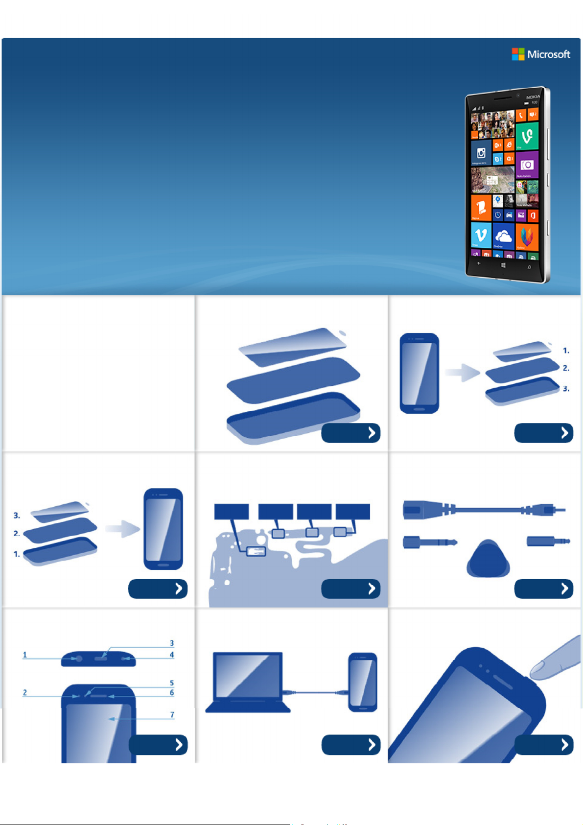
Exploded view Disassembly steps
More More
Assembly hints Solder components Service devices
More More More
Product controls and interfaces Service concept Phone reset
More More More

Service Manual Level 1 and 2
V
0
y
©2014 Microsoft | Microsoft Internal Use only | All Rights Reserved.
Nokia Lumia 930
RM-1045
ersion 1.
Version Date Description
1.0 29.05.2014 First published version
Version histor
Service Manual Level 1 and 2
©2014 Microsoft | Microsoft Internal Use only | All Rights Reserved.
Nokia Lumia 930
RM-1045
Version 1.0
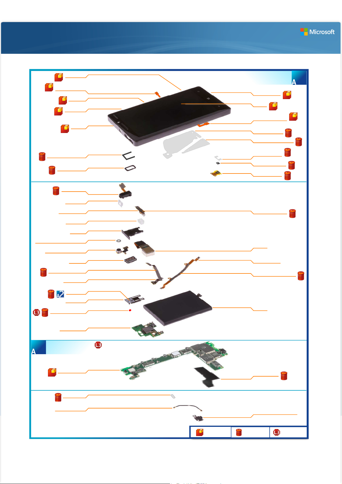
Exploded view
CAMERA KEY
MAIN ANTENNA LTE
DAUGHTER PWB GASKET
EARPIECE GASKET
SKYPE CAMERA WINDOW GASKET
SKYPE CAMERA ASSEMBLY
JUMPER FLEX ADHESIVE
WATER INGRESS LABEL
I0007
COAX FLEX
I0005
LOCK KEY
I0008
VOLUME KEY
I0009
CHASSIS
I0004
I0016
I0015
HSJ ASSEMBLY
I0036
HSJ GASKET
I0037
VIBRA ASSEMBLY
I0019
VIBRA BOOT
I0021
SIM TRAY
I0001
I0018
I0017
EARPIECE
I0022
I0027
JUMPER FLEX
I0026
TYPE LABEL
I0040
LABEL TRAY
I0024
I0025
CARE UI ASSEMBLY
(I0002 - I0016)
DISPLAY WINDOW
I0002
DISPLAY
I0003
MAIN ANTENNA VOICE
COAX FLEX
I0006
BATTERY ADHESIVE
I0010
SMALL BATTERY ADHESIVE
I0011
PRIMARY MIC FLEX
ADHESIVE
I0014
PRIMARY MIC GASKET
I0013
PRIMARY MIC FLEX
I0012
VIBRA FLEX ADHESIVE
I0020
CAMERA
I0023
MIMO COAX FLEX
I0028
MIMO COAX FLEX ADHESIVE
I0029
BATTERY
I0032
1
DAUGHTER PWB
I0035
LIGHT SWAP PACKAGE
(I0038 - I0040)
2
LIGHT SWAP PWB
I0038
LTE ADHESIVE
I0031
LTE RF COAX CABLE
I0030
Only available
as assembly
HEAT SPREADER
I0039
BATTERY CONNECTOR STRAP
I0033
Not reuseable
after removal
1/2
Repair/swap
only in level 3
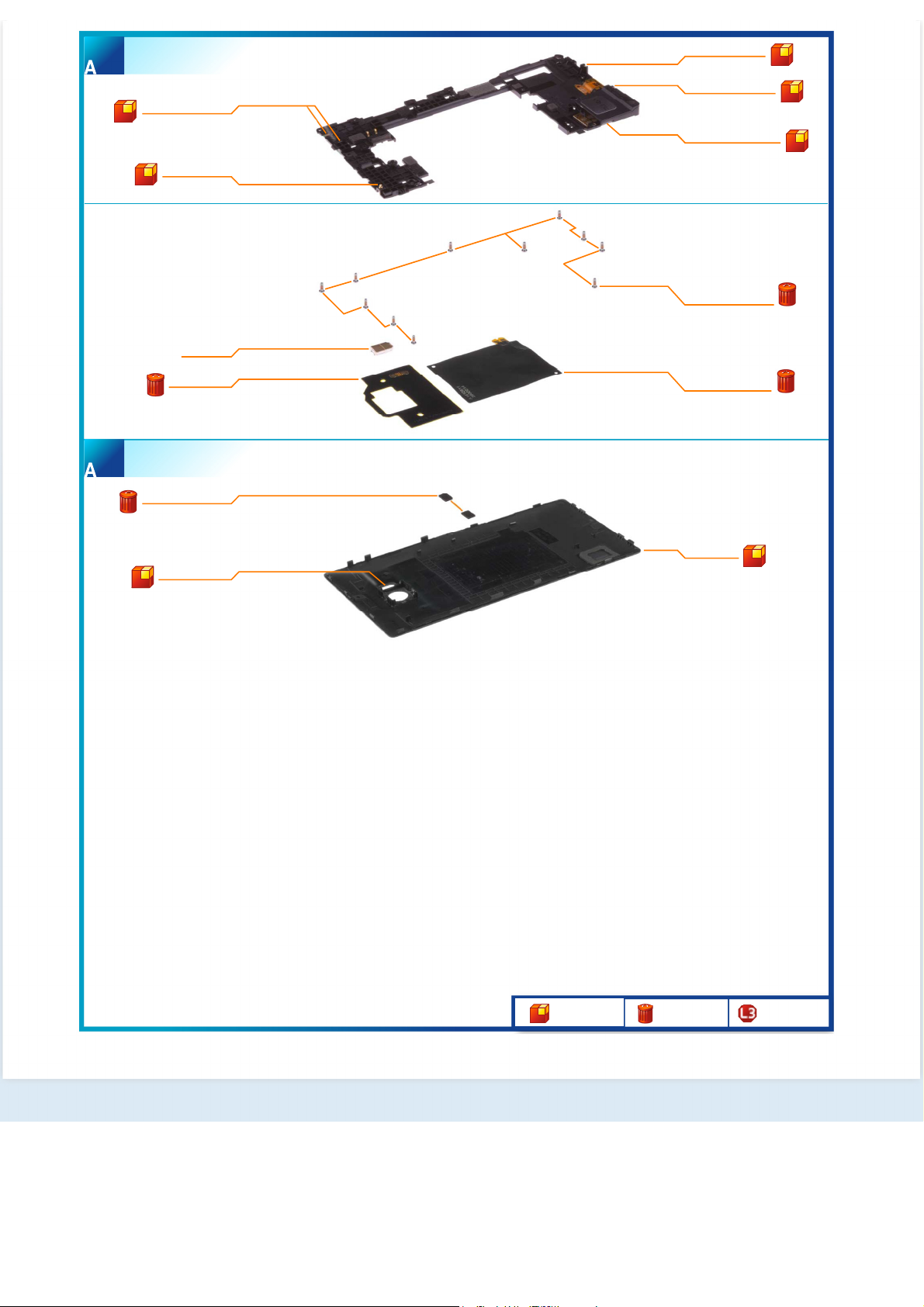
ENGINE COVER ASSEMBLY
©2014 Microsoft | Microsoft Internal Use only | All Rights Reserved.
(I0041 - I0045)
3
GPS/WLAN ANTENNA
MIMO ANTENNA
LED FLASH
NFC ANTENNA
BACK COVER ASSEMBLY
(I0046 - I0048)
4
BACK COVER GASKET
I0042
I0043
I0049
I0051
I0048
MAIN ANTENNA LTE
I0044
MAIN ANTENNA VOICE
I0045
IHF SPEAKER ASSEMBLY
I0041
SCREW TORX+ SIZE 4
M1.4 X 3.8
I0034
WIRELESS CHARGING
ASSEMBLY
I0050
FLASH ADHESIVE
I0047
Only available
as assembly
BACK COVER
I0046
Not reuseable
after removal
2/2
Repair/swap
only in level 3
Service Manual Level 1 and 2
0
©2014 Microsoft | Microsoft Internal Use only | All Rights Reserved.
Nokia Lumia 93
RM-1045
Version 1.0
Disassembly steps
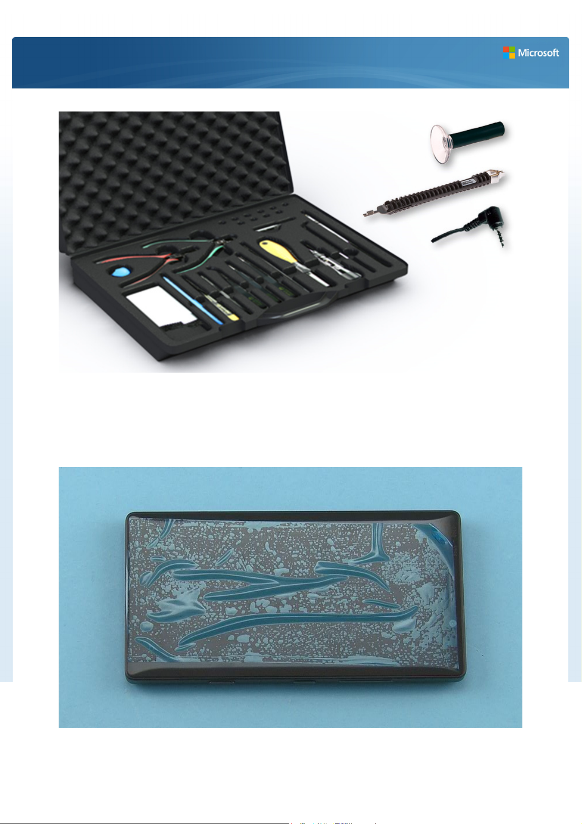
1) For disassembling you need the Nokia Standard toolkit version 2. You will also need the SS-311 back
cover release tool, the SS-319 RF-connector disassembly/assembly tool and an AV jack.
Note that the device shown in most of these pictures is the Nokia Lumia Icon. On those steps the spare
parts and the disassembly procedures are the same.
2) Protect the DISPLAY WINDOW with protective film.
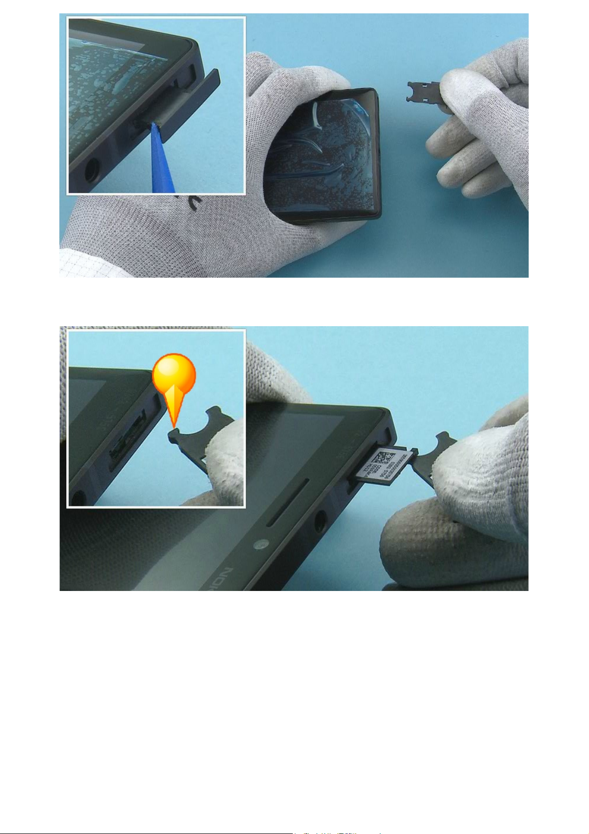
3) Open the SIM TRAY with the SS-93 and pull it out.
©2014 Microsoft | Microsoft Internal Use only | All Rights Reserved.
4) At this point, if you only want to check the TYPE LABEL without having to disassemble the phone, you
can pull the LABEL TRAY out with the hook on the SIM TRAY.
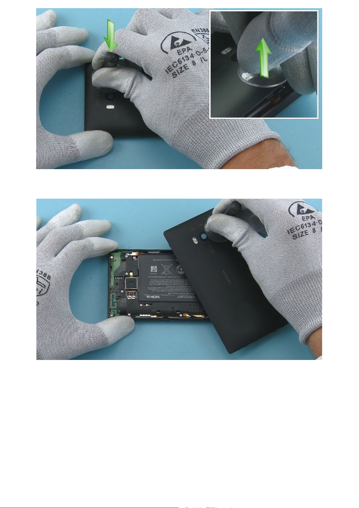
5) Release the BACK COVER with the SS-311 from the shown corner.
©2014 Microsoft | Microsoft Internal Use only | All Rights Reserved.
6) Remove the BACK COVER.
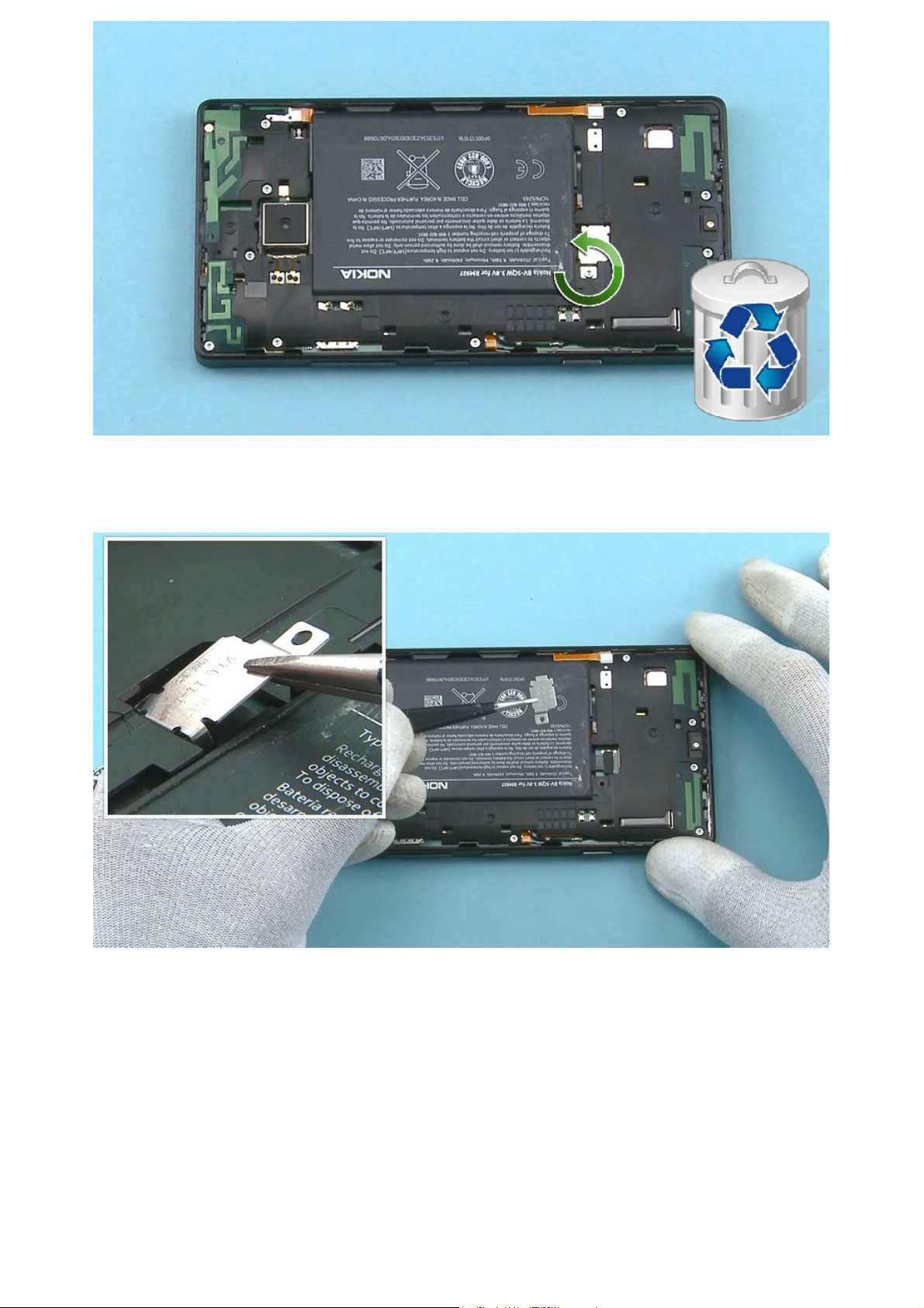
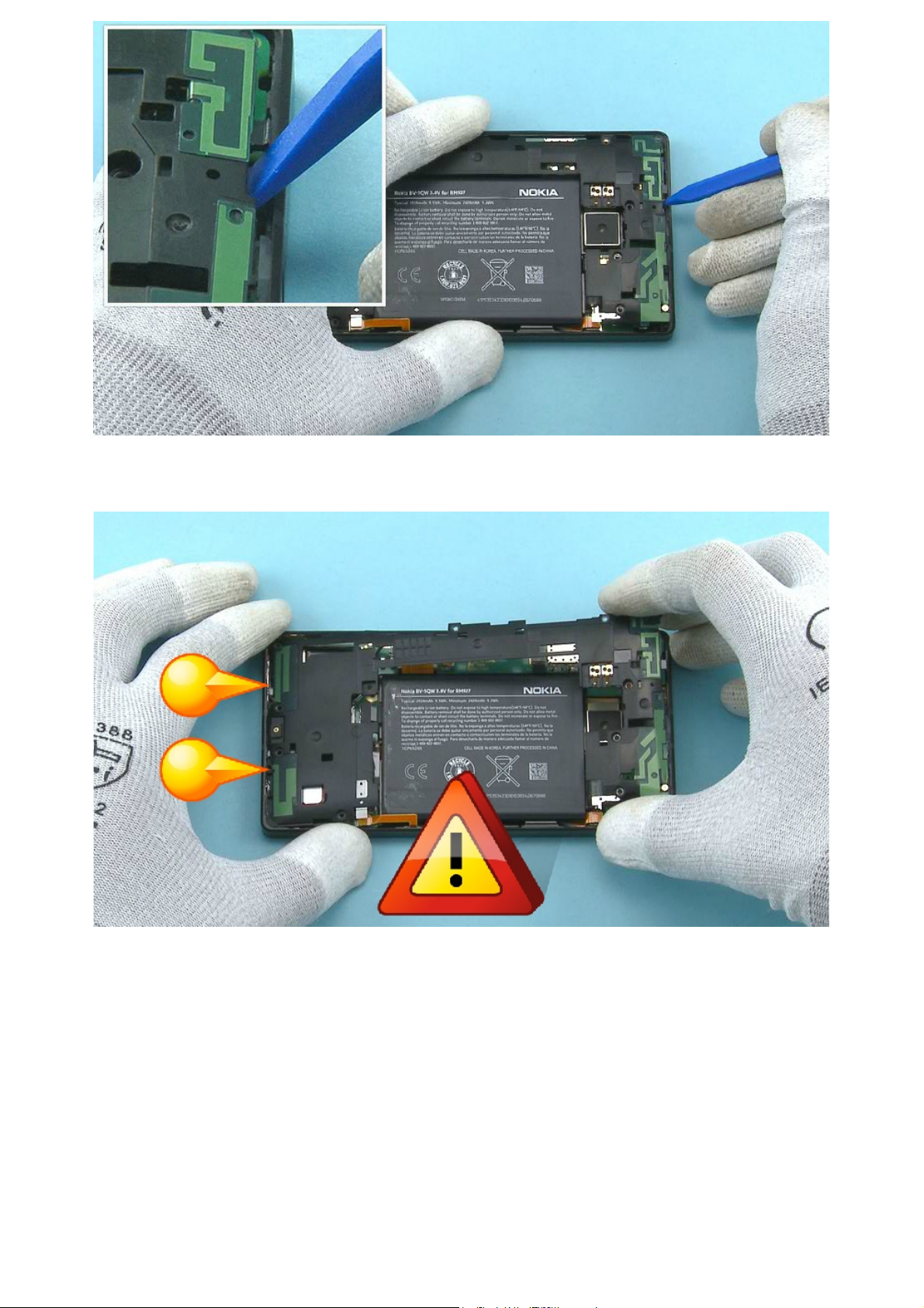
7) Unscrew the TORX+ SIZE 4 screw on top of the BATTERY CONNECTOR STRAP. Do not use the screw
©2014 Microsoft | Microsoft Internal Use only | All Rights Reserved.
again. Discard it.
8) Remove the BATTERY CONNECTOR STRAP with tweezers.
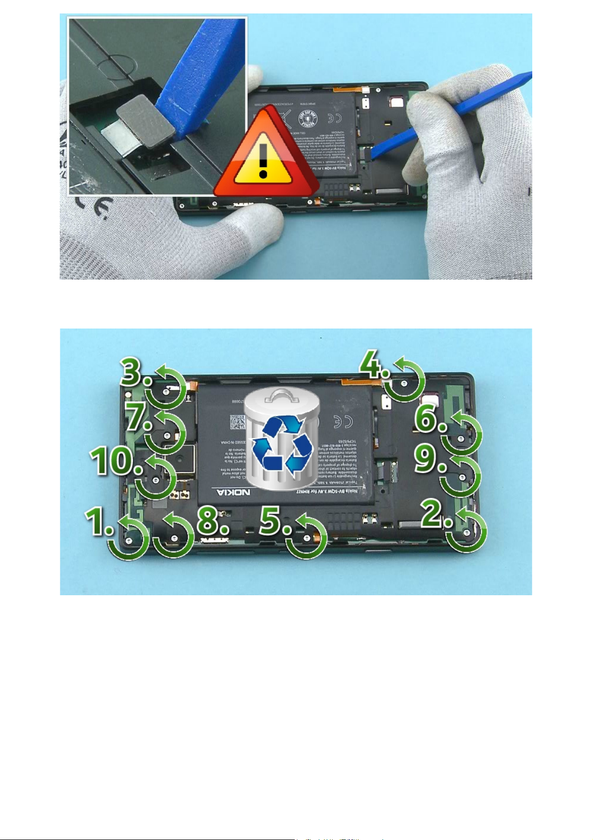
9) Disconnect the BATTERY connector with the SS-93. Be careful not to damage the connector.
©2014 Microsoft | Microsoft Internal Use only | All Rights Reserved.
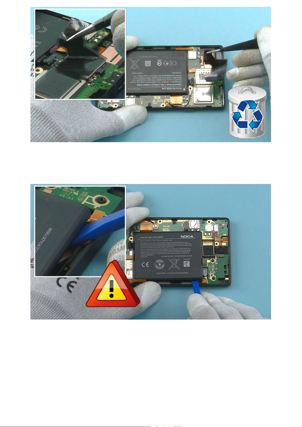
10) Unscrew the ten TORX+ SIZE 4 screws in the order shown. Do not use the screws again. Discard them.
11) Release the ENGINE COVER ASSEMBLY from the shown place with the SS-93.
©2014 Microsoft | Microsoft Internal Use only | All Rights Reserved.
12) Lift up and remove the ENGINE COVER ASSEMBLY top end first. Be careful not to damage the antenna
spring contacts on the bottom of the ENGINE COVER ASSEMBLY.
13) Remove the HEAT SPREADER with tweezers. Do not use it again. Discard it.
©2014 Microsoft | Microsoft Internal Use only | All Rights Reserved.
Note that the HEAT SPREADER needs to be removed completely ONLY when the ENGINE BOARD requires
repair work.
14) Release the BATTERY from the shown place with the SS-93. Be careful not to damage the two flexes
located under the BATTERY.
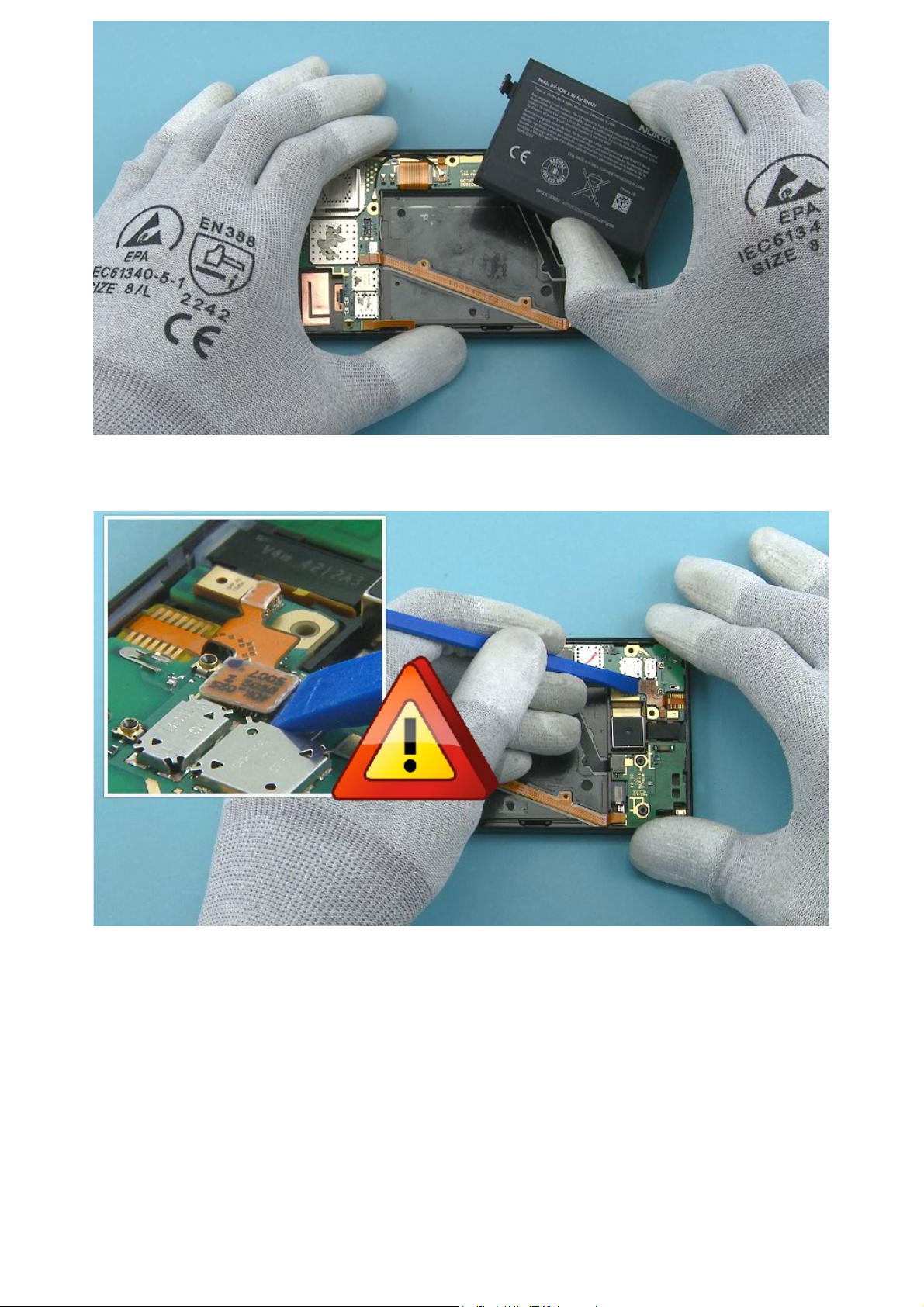
15) Remove the BATTERY.
©2014 Microsoft | Microsoft Internal Use only | All Rights Reserved.
16) Disconnect the SKYPE CAMERA connector from the shown edge with the SS-93. Be careful not to
damage the connector or any components nearby.
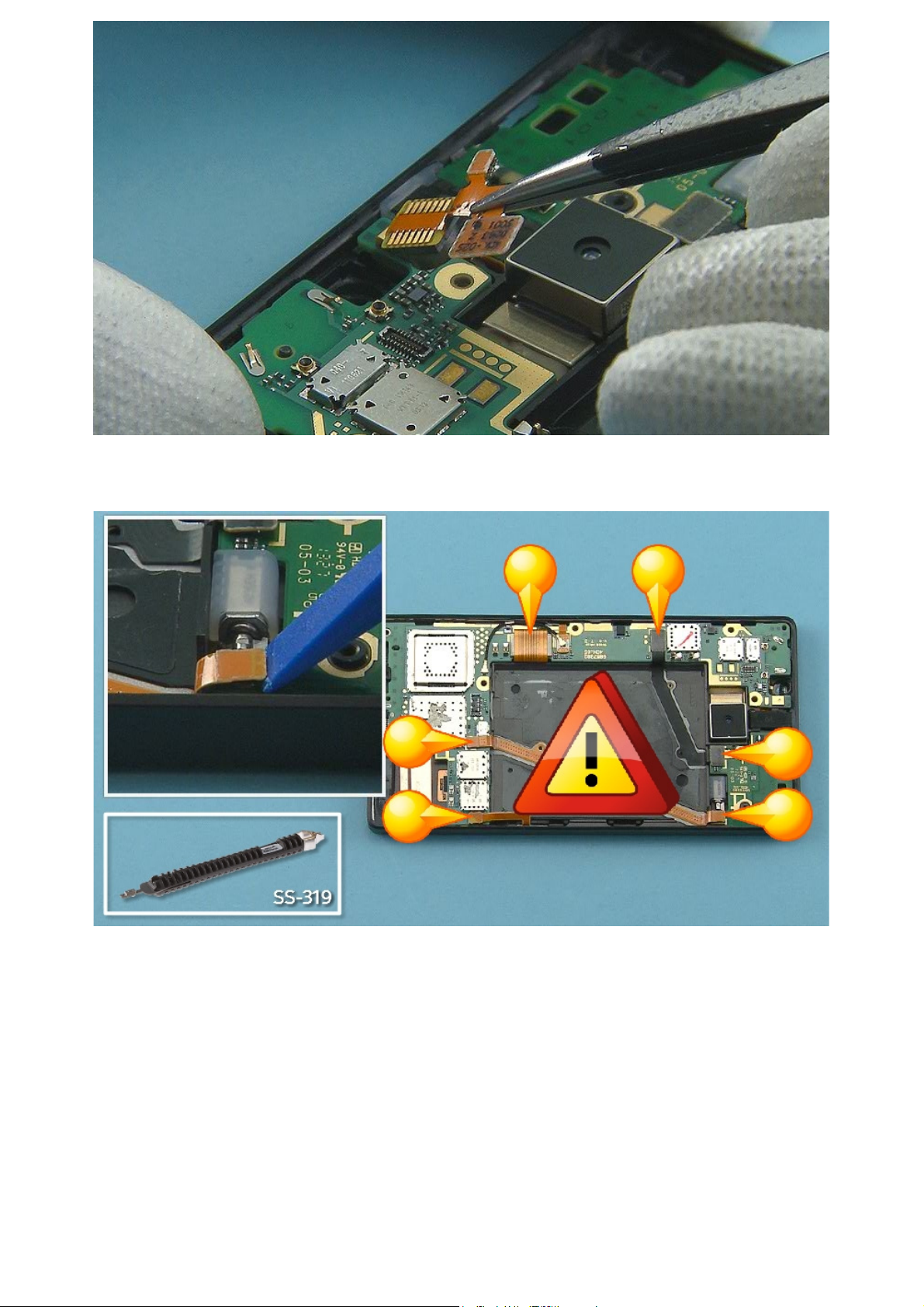
17) Remove the SKYPE CAMERA with tweezers.
©2014 Microsoft | Microsoft Internal Use only | All Rights Reserved.
18) Disconnect the six shown connectors with the SS-93. Be careful not to damage the connectors or any
components nearby.
Note that the SS-319 can also be used to disconnect the connectors.
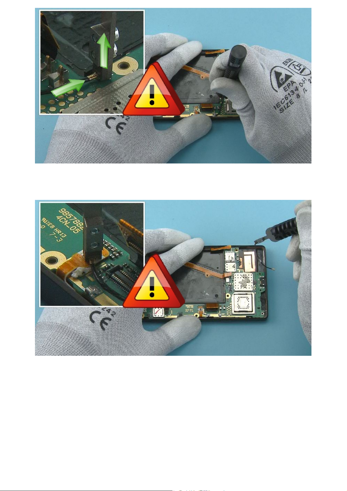
19) Release the RF CABLE connector with the SS-319. Lock the SS-319 to the top of the connector as
©2014 Microsoft | Microsoft Internal Use only | All Rights Reserved.
shown and lift it up carefully. Be careful not to damage the connector.
20) Release also the other end of the RF CABLE and remove it.
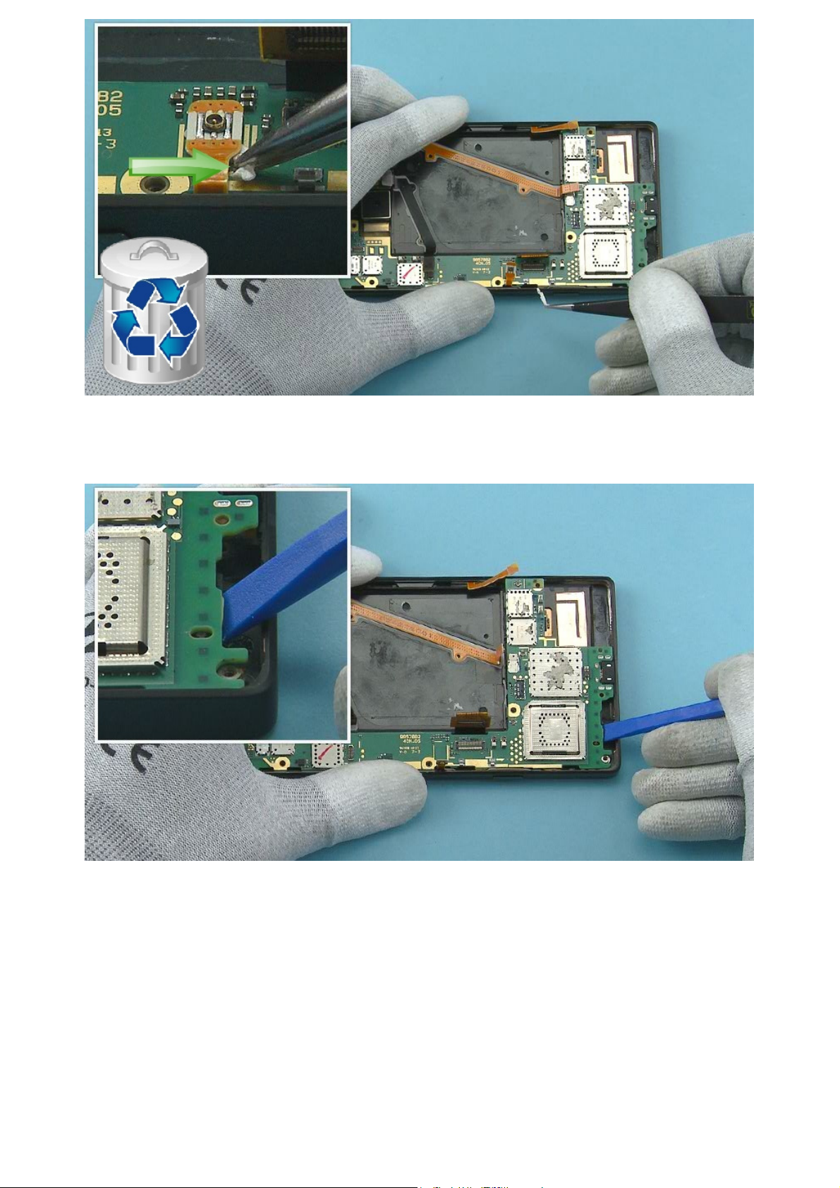
21) Pull the LTE ADHESIVE to the direction shown to remove it under the LTE FLEX. Do not use it again.
©2014 Microsoft | Microsoft Internal Use only | All Rights Reserved.
Discard it.
22) Release the ENGINE BOARD from the shown place with the SS-93.
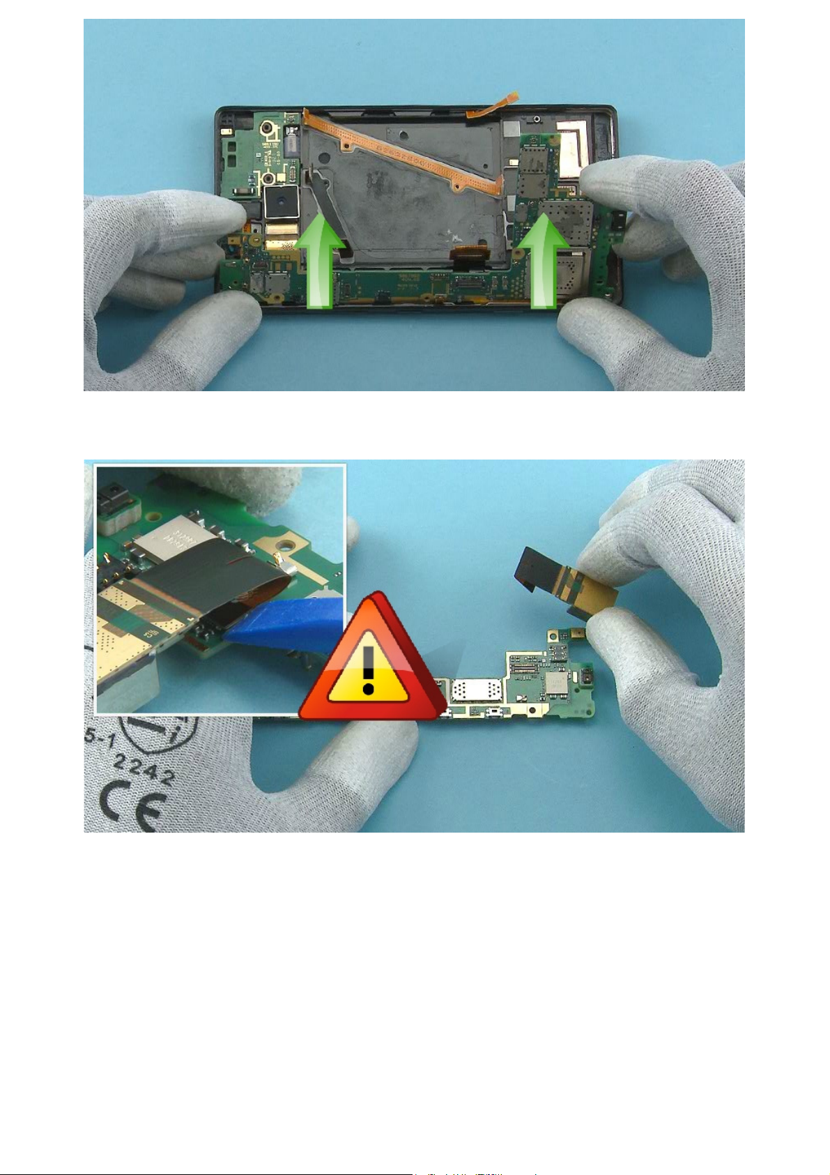
23) Lift up the other side and remove the ENGINE BOARD to the direction shown.
©2014 Microsoft | Microsoft Internal Use only | All Rights Reserved.
24) Disconnect the CAMERA connector from the shown edge with the SS-93. Be careful not to damage the
connector or any components nearby. Remove the CAMERA.
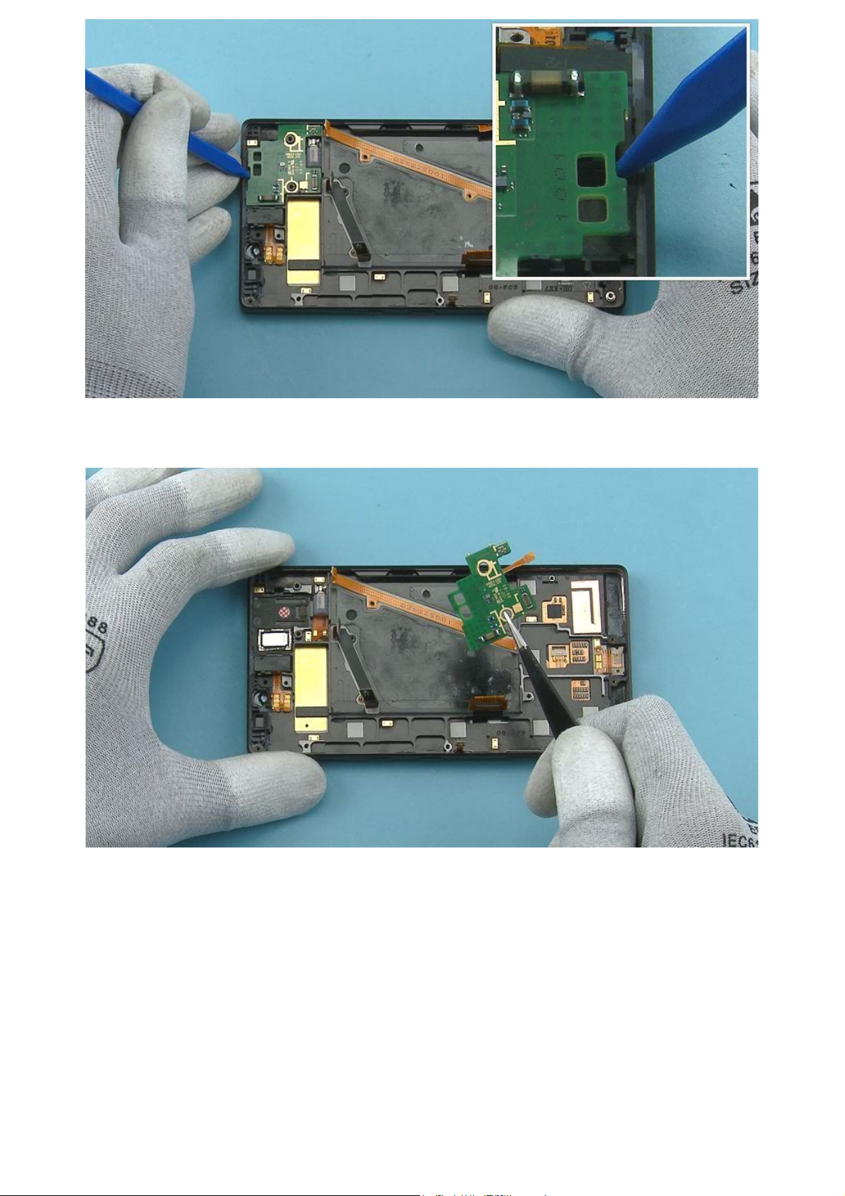
25) Release the DAUGHTER ENGINE BOARD from the shown place with the sharp end of the SS-93.
©2014 Microsoft | Microsoft Internal Use only | All Rights Reserved.
26) Remove the DAUGHTER ENGINE BOARD.
 Loading...