

Page 1

Nokia Customer Care
Service Manual
RM-244 (Nokia E51)
Mobile Terminal
Part No: (Issue 1)
COMPANY CONFIDENTIAL
Copyright © 2007 Nokia. All rights reserved.
Page 2

Amendment Record Sheet
Amendment Record Sheet
Amendment No Date Inserted By Comments
Issue 1 10/2007 TSa
RM-244
Page ii COMPANY CONFIDENTIAL Issue 1
Copyright © 2007 Nokia. All rights reserved.
Page 3

RM-244
Copyright
Copyright
Copyright © 2007 Nokia. All rights reserved.
Reproduction, transfer, distribution or storage of part or all of the contents in this document in any form
without the prior written permission of Nokia is prohibited.
Nokia, Nokia Connecting People, and Nokia X and Y are trademarks or registered trademarks of Nokia
Corporation. Other product and company names mentioned herein may be trademarks or tradenames of
their respective owners.
Nokia operates a policy of continuous development. Nokia reserves the right to make changes and
improvements to any of the products described in this document without prior notice.
Under no circumstances shall Nokia be responsible for any loss of data or income or any special, incidental,
consequential or indirect damages howsoever caused.
The contents of this document are provided "as is". Except as required by applicable law, no warranties of
any kind, either express or implied, including, but not limited to, the implied warranties of merchantability
and fitness for a particular purpose, are made in relation to the accuracy, reliability or contents of this
document. Nokia reserves the right to revise this document or withdraw it at any time without prior notice.
The availability of particular products may vary by region.
IMPORTANT
This document is intended for use by qualified service personnel only.
Issue 1 COMPANY CONFIDENTIAL Page iii
Copyright © 2007 Nokia. All rights reserved.
Page 4

RM-244
Warnings and cautions
Warnings and cautions
Warnings
• IF THE DEVICE CAN BE INSTALLED IN A VEHICLE, CARE MUST BE TAKEN ON INSTALLATION IN VEHICLES FITTED
WITH ELECTRONIC ENGINE MANAGEMENT SYSTEMS AND ANTI-SKID BRAKING SYSTEMS. UNDER CERTAIN FAULT
CONDITIONS, EMITTED RF ENERGY CAN AFFECT THEIR OPERATION. IF NECESSARY, CONSULT THE VEHICLE DEALER/
MANUFACTURER TO DETERMINE THE IMMUNITY OF VEHICLE ELECTRONIC SYSTEMS TO RF ENERGY.
• THE PRODUCT MUST NOT BE OPERATED IN AREAS LIKELY TO CONTAIN POTENTIALLY EXPLOSIVE ATMOSPHERES,
FOR EXAMPLE, PETROL STATIONS (SERVICE STATIONS), BLASTING AREAS ETC.
• OPERATION OF ANY RADIO TRANSMITTING EQUIPMENT, INCLUDING CELLULAR TELEPHONES, MAY INTERFERE
WITH THE FUNCTIONALITY OF INADEQUATELY PROTECTED MEDICAL DEVICES. CONSULT A PHYSICIAN OR THE
MANUFACTURER OF THE MEDICAL DEVICE IF YOU HAVE ANY QUESTIONS. OTHER ELECTRONIC EQUIPMENT MAY
ALSO BE SUBJECT TO INTERFERENCE.
• BEFORE MAKING ANY TEST CONNECTIONS, MAKE SURE YOU HAVE SWITCHED OFF ALL EQUIPMENT.
Cautions
• Servicing and alignment must be undertaken by qualified personnel only.
• Ensure all work is carried out at an anti-static workstation and that an anti-static wrist strap is worn.
• Ensure solder, wire, or foreign matter does not enter the telephone as damage may result.
• Use only approved components as specified in the parts list.
• Ensure all components, modules, screws and insulators are correctly re-fitted after servicing and
alignment.
• Ensure all cables and wires are repositioned correctly.
• Never test a mobile phone WCDMA transmitter with full Tx power, if there is no possibility to perform the
measurements in a good performance RF-shielded room. Even low power WCDMA transmitters may disturb
nearby WCDMA networks and cause problems to 3G cellular phone communication in a wide area.
• During testing never activate the GSM or WCDMA transmitter without a proper antenna load, otherwise
GSM or WCDMA PA may be damaged.
Page iv COMPANY CONFIDENTIAL Issue 1
Copyright © 2007 Nokia. All rights reserved.
Page 5

RM-244
ESD protection
ESD protection
Nokia requires that service points have sufficient ESD protection (against static electricity) when servicing
the phone.
Any product of which the covers are removed must be handled with ESD protection. The SIM card can be
replaced without ESD protection if the product is otherwise ready for use.
To replace the covers ESD protection must be applied.
All electronic parts of the product are susceptible to ESD. Resistors, too, can be damaged by static electricity
discharge.
All ESD sensitive parts must be packed in metallized protective bags during shipping and handling outside
any ESD Protected Area (EPA).
Every repair action involving opening the product or handling the product components must be done under
ESD protection.
ESD protected spare part packages MUST NOT be opened/closed out of an ESD Protected Area.
For more information and local requirements about ESD protection and ESD Protected Area, contact your local
Nokia After Market Services representative.
Issue 1 COMPANY CONFIDENTIAL Page v
Copyright © 2007 Nokia. All rights reserved.
Page 6

RM-244
Care and maintenance
Care and maintenance
This product is of superior design and craftsmanship and should be treated with care. The suggestions below
will help you to fulfil any warranty obligations and to enjoy this product for many years.
• Keep the phone and all its parts and accessories out of the reach of small children.
• Keep the phone dry. Precipitation, humidity and all types of liquids or moisture can contain minerals that
will corrode electronic circuits.
• Do not use or store the phone in dusty, dirty areas. Its moving parts can be damaged.
• Do not store the phone in hot areas. High temperatures can shorten the life of electronic devices, damage
batteries, and warp or melt certain plastics.
• Do not store the phone in cold areas. When it warms up (to its normal temperature), moisture can form
inside, which may damage electronic circuit boards.
• Do not drop, knock or shake the phone. Rough handling can break internal circuit boards.
• Do not use harsh chemicals, cleaning solvents, or strong detergents to clean the phone.
• Do not paint the phone. Paint can clog the moving parts and prevent proper operation.
• Use only the supplied or an approved replacement antenna. Unauthorised antennas, modifications or
attachments could damage the phone and may violate regulations governing radio devices.
All of the above suggestions apply equally to the product, battery, charger or any accessory.
Page vi COMPANY CONFIDENTIAL Issue 1
Copyright © 2007 Nokia. All rights reserved.
Page 7

RM-244
Company Policy
Company Policy
Our policy is of continuous development; details of all technical modifications will be included with service
bulletins.
While every endeavour has been made to ensure the accuracy of this document, some errors may exist. If
any errors are found by the reader, NOKIA MOBILE PHONES Business Group should be notified in writing/email.
Please state:
• Title of the Document + Issue Number/Date of publication
• Latest Amendment Number (if applicable)
• Page(s) and/or Figure(s) in error
Please send to:
NOKIA CORPORATION
Nokia Mobile Phones Business Group
Nokia Customer Care
PO Box 86
FIN-24101 SALO
Finland
E-mail: Service.Manuals@nokia.com
Issue 1 COMPANY CONFIDENTIAL Page vii
Copyright © 2007 Nokia. All rights reserved.
Page 8

RM-244
Battery information
Battery information
Note: A new battery's full performance is achieved only after two or three complete charge and
discharge cycles!
The battery can be charged and discharged hundreds of times but it will eventually wear out. When the
operating time (talk-time and standby time) is noticeably shorter than normal, it is time to buy a new battery.
Use only batteries approved by the phone manufacturer and recharge the battery only with the chargers
approved by the manufacturer. Unplug the charger when not in use. Do not leave the battery connected to
a charger for longer than a week, since overcharging may shorten its lifetime. If left unused a fully charged
battery will discharge itself over time.
Temperature extremes can affect the ability of your battery to charge.
For good operation times with Li-Ion batteries, discharge the battery from time to time by leaving the product
switched on until it turns itself off (or by using the battery discharge facility of any approved accessory
available for the product). Do not attempt to discharge the battery by any other means.
Use the battery only for its intended purpose.
Never use any charger or battery which is damaged.
Do not short-circuit the battery. Accidental short-circuiting can occur when a metallic object (coin, clip or
pen) causes direct connection of the + and - terminals of the battery (metal strips on the battery) for example
when you carry a spare battery in your pocket or purse. Short-circuiting the terminals may damage the battery
or the connecting object.
Leaving the battery in hot or cold places, such as in a closed car in summer or winter conditions, will reduce
the capacity and lifetime of the battery. Always try to keep the battery between 15°C and 25°C (59°F and 77°
F). A phone with a hot or cold battery may temporarily not work, even when the battery is fully charged.
Batteries' performance is particularly limited in temperatures well below freezing.
Do not dispose of batteries in a fire!
Dispose of batteries according to local regulations (e.g. recycling). Do not dispose as household waste.
Page viii COMPANY CONFIDENTIAL Issue 1
Copyright © 2007 Nokia. All rights reserved.
Page 9

RM-244
Nokia E51 Service Manual Structure
Nokia E51 Service Manual Structure
1 General Information
2 Service Tools and Service Concepts
3 BB Troubleshooting and Manual Tuning Guide
4 RF troubleshooting
5 Camera Module Troubleshooting
6 System Module and User Interface
Glossary
Issue 1 COMPANY CONFIDENTIAL Page ix
Copyright © 2007 Nokia. All rights reserved.
Page 10

RM-244
Nokia E51 Service Manual Structure
(This page left intentionally blank.)
Page x COMPANY CONFIDENTIAL Issue 1
Copyright © 2007 Nokia. All rights reserved.
Page 11
Nokia Customer Care
1 — General Information
Issue 1 COMPANY CONFIDENTIAL Page 1 –1
Copyright © 2007 Nokia. All rights reserved.
Page 12

RM-244
General Information
(This page left intentionally blank.)
Page 1 –2 COMPANY CONFIDENTIAL Issue 1
Copyright © 2007 Nokia. All rights reserved.
Page 13

RM-244
General Information
Table of Contents
Product selection....................................................................................................................................................1–5
Product features and sales package.....................................................................................................................1–5
Product and module list ........................................................................................................................................1–7
Mobile enhancements............................................................................................................................................1–7
Technical specifications.........................................................................................................................................1–8
Transceiver general specifications ..................................................................................................................1–8
Main RF characteristics for GSM850/900/1800/1900 and WCDMA V (850) and WCDMA I (2100) phones
..................................................................................................................................................................1–9
Battery endurance.......................................................................................................................................... 1–10
List of Tables
Table 1 Audio..........................................................................................................................................................1–7
Table 2 Car...............................................................................................................................................................1–7
Table 3 Carrying......................................................................................................................................................1–8
Table 4 Data & positioning....................................................................................................................................1–8
Table 5 Messaging..................................................................................................................................................1–8
Table 6 Music ..........................................................................................................................................................1–8
Table 7 Power.........................................................................................................................................................1–8
Table 8 GSM.......................................................................................................................................................... 1–10
Table 9 WCDMA .................................................................................................................................................... 1–10
List of Figures
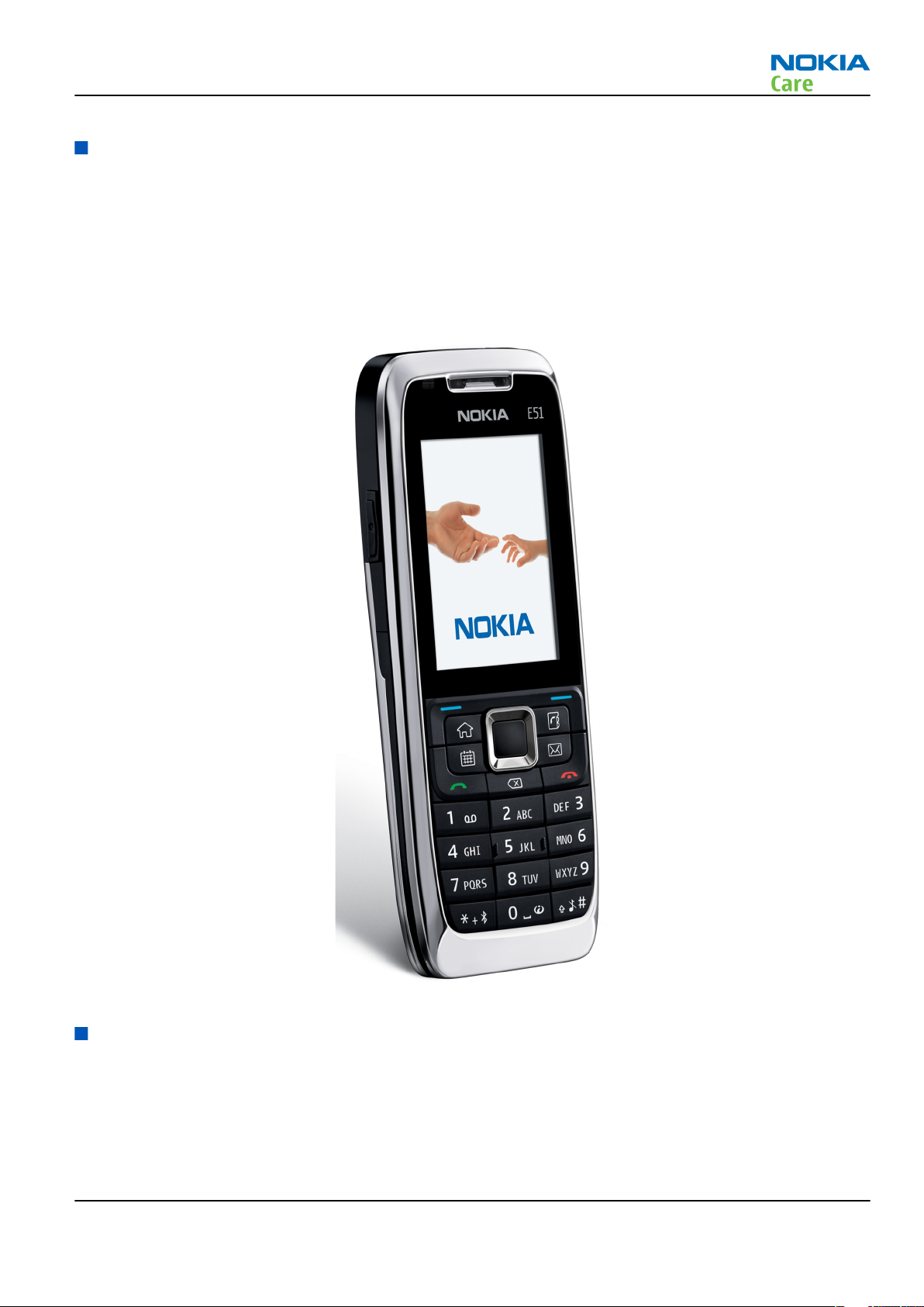
Figure 1 View of RM-244........................................................................................................................................1–5
Issue 1 COMPANY CONFIDENTIAL Page 1 –3
Copyright © 2007 Nokia. All rights reserved.
Page 14

RM-244
General Information
(This page left intentionally blank.)
Page 1 –4 COMPANY CONFIDENTIAL Issue 1
Copyright © 2007 Nokia. All rights reserved.
Page 15
RM-244
General Information
Product selection
RM-244 is a WCDMA/GSM mode handportable phone. RM-244 supports EGSM850/900/1800/1900 and
WCDMA850 and 2100.
RM-244 supports Bluetooth 2.0 + EDR standard. It has an integrated 2Mp camera.
RM-244 is an MMS (Multimedia Messaging Service) enabled multimedia device. The MMS implementation
follows the OMA MMS standard release 1.2.
RM-244 uses Symbian 9.2 (S60) operating system and supports also MIDP Java 2.0, providing a good platform
for compelling 3rd party applications.
Figure 1 View of RM-244
Product features and sales package
Hardware characteristics
Connectivity
• Thin voice monoblock device
• Up to 150 MB of user data memory
Issue 1 COMPANY CONFIDENTIAL Page 1 –5
Copyright © 2007 Nokia. All rights reserved.
Page 16

• 96 MB RAM
• microSD (hot swap) memory card
• Integrated handsfree speaker
• Internal vibra
• Integrated camera, 2 Megapixel
• Ambient light sensor
• LED for e-mail, SMS/MMS and missed call indication
• GSM850/900/1800/1900, WCMA 850/2100
• GSM rel. 5
• GPRS/EGPRS (Class A, MSC 32)
• Dual mode transfer MSC11, SAIC rel v1
• HSDPA up to 3.6Mbit/s
• Speech codecs AMR, FR and EFR (HR)
• Integrated WLAN (IEEE 802.11g)
• Bluetooth 2.0 + EDR
• Mini USB connector, USB 2.0 full-speed
• 2.5mm Nokia A/V connector with ECI
• IrDA (115 kbps)
RM-244
General Information
User Interface & developer platform
• Symbian 9.2
• Nokia Series 60, 3rd edition, feature pack 3.1
• Java: MIDP2.0
• Viewer & Editor font zooming
Display and Keypad
• Active matrix colour 2” display (240 x 320), 16M colors
• 5-way rocker, 2 soft keys, send and end keys
• Nokia Eseries keys (Phonebook, E-mail, Calendar and Home key)
• Mute key and volume keys on right hand side
• Poc/Voice recorder key on left hand side
• Power key on top of phone
Media
• Gallery, MP3 player
• Sideway picture taking, Volume keys as zoom
• Bluetooth stereo audio
• FM radio and visual radio
Page 1 –6 COMPANY CONFIDENTIAL Issue 1
Copyright © 2007 Nokia. All rights reserved.
Page 17
RM-244
General Information
Product and module list
Module name Type code Notes
System/RF Module 2AV Main PWB with components.
uSD/SIM card Module 2CK
UI Flex Module 2CL
Mobile enhancements
Table 1 Audio
Enhancement Type
Wired headsets HS-40
HS-47
HS-81
Wireless headsets HDW-3
HS-4W
HS-11W
HS-13W
HS-21W
HS-26W
HS-36W
HS-37W
Loopsets TTY adapter HDA-11
Table 2 Car
Enhancement Type
Mobile holder CR-39
Mobile holder mounting device HH-12
Mobile charger DC-4
Car kit N616
Wireless car kit CK-1W
CK-7W
CK-20W
Wireless plug-in car handsfree HF-6W
Car phone N810
Privacy handset HSU-4
Issue 1 COMPANY CONFIDENTIAL Page 1 –7
Copyright © 2007 Nokia. All rights reserved.
Page 18
Table 3 Carrying
Enhancement Type
Carrying case xx
Table 4 Data & positioning
Enhancement Type
MicroSD card, 128MB MU-26
MicroSD card, 256MB MU-27
MicroSD card, 512MB MU-28
MicroSD card, 1GB MU-22
MicroSD card, 2GB MU-37
Mini USB connectivity adapter cable DKE-2
Wireless GPS module LD-3W
RM-244
General Information
Table 5 Messaging
Enhancement Type
Digital pen SU-27W
Wireless keyboard SU-8W
Table 6 Music
Enhancement Type
Mini speakers MD-4
Table 7 Power
Enhancement Type
Battery Li-Ion 1050 mAh BP-6MT
Travel charger AC-5
Charger adapter CA-44
Technical specifications
Transceiver general specifications
Unit Dimensions (L x W x T)
(mm)
Transceiver with BP-6MT
114,8 x 46 x 12,5 99 61
Li-Ion battery back
Page 1 –8 COMPANY CONFIDENTIAL Issue 1
Copyright © 2007 Nokia. All rights reserved.
Weight (g) Volume (cm3)
Page 19
RM-244
General Information
Main RF characteristics for GSM850/900/1800/1900 and WCDMA V (850) and WCDMA I (2100) phones
Parameter Unit
Cellular system GSM850, EGSM900, GSM1800/1900, WCDMA V (850)
and WCDMA I (2100)
Rx frequency band GSM850: 869 - 894 MHz
EGSM900: 925 - 960 MHz
GSM1800: 1805 - 1880 MHz
GSM1900: 1930 - 1990 MHz
WCDMA V (850): 871 - 892 MHz
WCDMA I (2100): 2110 - 2170 MHz
Tx frequency band GSM850: 824 - 849 MHz
EGSM900: 880 - 915 MHz
GSM1800: 1710 - 1785 MHz
GSM1900: 1850 - 1910 MHz
WCDMA V (850): 826 - 847 MHz
WCDMA I (2100): 1920 - 1980 MHz
Output power GSM850: +5 ...+33dBm/3.2mW ... 2W
GSM900: +5 … +33dBm/3.2mW … 2W
GSM1800: +0 … +30dBm/1.0mW … 1W
GSM1900: +0 … +30dBm/1.0mW … 1W
WCDMA V (850): -50 ... +24 dBm/0.01μW ... 251.2mW
WCDMA I (2100): -50 ... +24 dBm/0.01μW ...
251.2mW
Number of RF channels GSM850: 124
GSM900: 174
GSM1800: 374
GSM1900: 299
WCDMA V (850): 108
WCDMA I (2100): 277
Channel spacing 200 kHz
Issue 1 COMPANY CONFIDENTIAL Page 1 –9
Copyright © 2007 Nokia. All rights reserved.
Page 20
General Information
Parameter Unit
Number of Tx power levels GSM850: 15
GSM900: 15
GSM1800: 16
GSM1900: 16
WCDMA V (850): 75
WCDMA I (2100): 75
Battery endurance
Table 8 GSM
Battery Capacity (mAh) Talk time Stand-by
BP-6MT 1050 up to 4 h 23 min up to 13 days
RM-244
Table 9 WCDMA
Battery Capacity (mAh) Talk time Stand-by
BP-6MT 1050 3 h 06 min up to 13 days
Charging times
BP-6MT
1.5h
Page 1 –10 COMPANY CONFIDENTIAL Issue 1
Copyright © 2007 Nokia. All rights reserved.
Page 21

Nokia Customer Care
2 — Service Tools and Service
Concepts
Issue 1 COMPANY CONFIDENTIAL Page 2 –1
Copyright © 2007 Nokia. All rights reserved.
Page 22

RM-244
Service Tools and Service Concepts
(This page left intentionally blank.)
Page 2 –2 COMPANY CONFIDENTIAL Issue 1
Copyright © 2007 Nokia. All rights reserved.
Page 23

RM-244
Service Tools and Service Concepts
Table of Contents
Service tools............................................................................................................................................................2–5
Product specific tools........................................................................................................................................2–5
FS-56..............................................................................................................................................................2–5
MJ-141 ...........................................................................................................................................................2–5
RJ-175 ............................................................................................................................................................2–5
SA-133 ...........................................................................................................................................................2–6
General tools......................................................................................................................................................2–6
CU-4................................................................................................................................................................2–7
FLS-5 ..............................................................................................................................................................2–8
FPS-10............................................................................................................................................................2–8
PK-1................................................................................................................................................................2–8
SB-6................................................................................................................................................................2–9
SB-7................................................................................................................................................................2–9
SRT-6..............................................................................................................................................................2–9
SS-46..............................................................................................................................................................2–9
SS-62........................................................................................................................................................... 2–10
SS-93........................................................................................................................................................... 2–10
SX-4............................................................................................................................................................. 2–10
Cables............................................................................................................................................................... 2–10
CA-31D ............................................................................................................................................................. 2–10
CA-35S.............................................................................................................................................................. 2–11
CA-53................................................................................................................................................................ 2–11
DKE-2................................................................................................................................................................ 2–11
PCS-1................................................................................................................................................................ 2–11
SS-102.............................................................................................................................................................. 2–12
XCS-4 ................................................................................................................................................................ 2–12
XRS-6................................................................................................................................................................ 2–12
Service concepts .................................................................................................................................................. 2–13
POS (Point of Sale) flash concept .................................................................................................................. 2–13
POS (Point of Sale) flash concept .................................................................................................................. 2–14
Module jig service concept............................................................................................................................ 2–15
Service concept for RF testing and RF/BB tuning........................................................................................ 2–16
Flash concept with FPS-10............................................................................................................................. 2–17
RF testing concept with RF coupler .............................................................................................................. 2–18
CU-4 flash concept with FPS-10..................................................................................................................... 2–19
List of Figures
Figure 2 POS flash concept ................................................................................................................................. 2–13
Figure 3 POS flash concept ................................................................................................................................. 2–14
Figure 4 Module jig service concept .................................................................................................................. 2–15
Figure 5 Service concept for RF testing and RF/BB tuning .............................................................................. 2–16
Figure 6 Basic flash concept with FPS-10.......................................................................................................... 2–17
Figure 7 RF testing concept with RF coupler .................................................................................................... 2–18
Figure 8 CU-4 flash concept with FPS-10........................................................................................................... 2–19
Issue 1 COMPANY CONFIDENTIAL Page 2 –3
Copyright © 2007 Nokia. All rights reserved.
Page 24

RM-244
Service Tools and Service Concepts
(This page left intentionally blank.)
Page 2 –4 COMPANY CONFIDENTIAL Issue 1
Copyright © 2007 Nokia. All rights reserved.
Page 25
RM-244
Service Tools and Service Concepts
Service tools
Product specific tools
The table below gives a short overview of service tools that can be used for testing, error analysis and repair
of product RM-244, refer to various concepts.
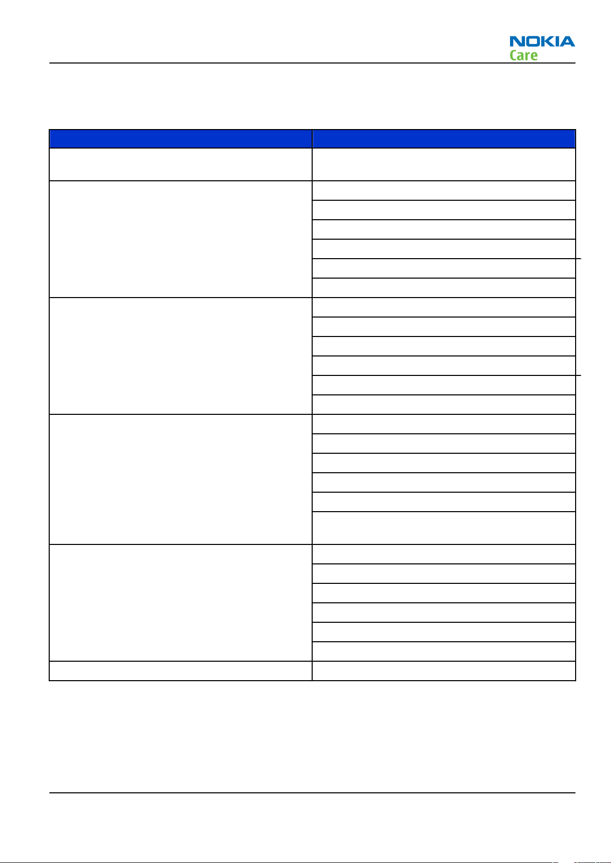
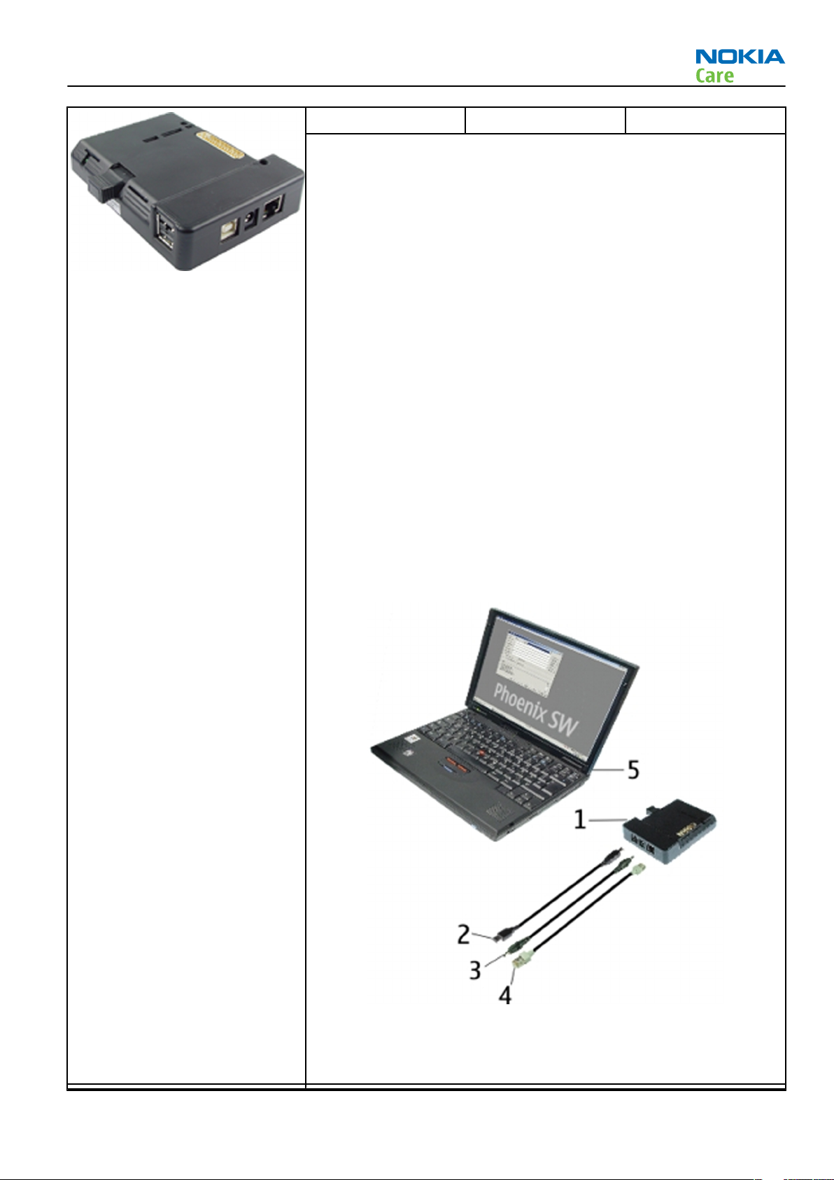
FS-56 Flash adapter Flash adapter FS-56 is used for phone testing and flashing. FS-56 is
used with the generic flash adapter base SS-60/62 and control unit
CU-4 or interface adapter SS-46.
When flashing or system testing the phone, the adapter is attached to
replace the phone own battery.
All functions (as well as the calibration voltages, current and the
protections for over voltages, over current and voltage polarity), are
performed by CU-4.
Flash adapter FS-56 main features:
• VBATT supply interface
• USB / FBUS multiplexed interface to the phone
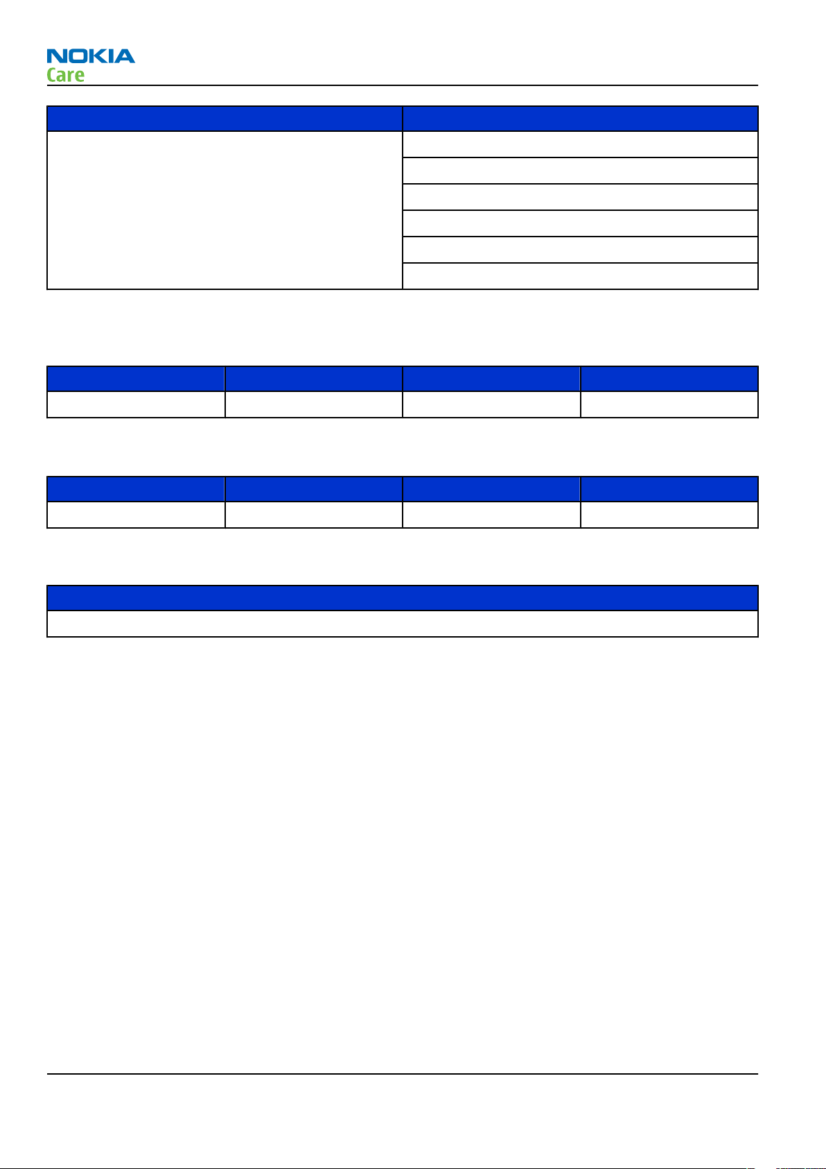
MJ-141 Module jig
MJ-141 can be used for flashing as well as for RF, battery and system
testing.
MJ-141 main functions:
• CU-4 interface adapter to phone
• FBUS interface to phone
• UI Interface to phone
• WCDMA and GSM RF-interface
All functions are performed in CU-4 e.g. calibration voltages and
currents both all protections (over current, over voltage and voltage
polarity).
MJ-141 contains following interfaces to phone:
• VBATT interface
• UI interface containing Display connector
• WCDMA and GSM RF interfaces
• Bluetooth RF interface
• Earpiece interface
• IHF speaker interface
• Microphone interface
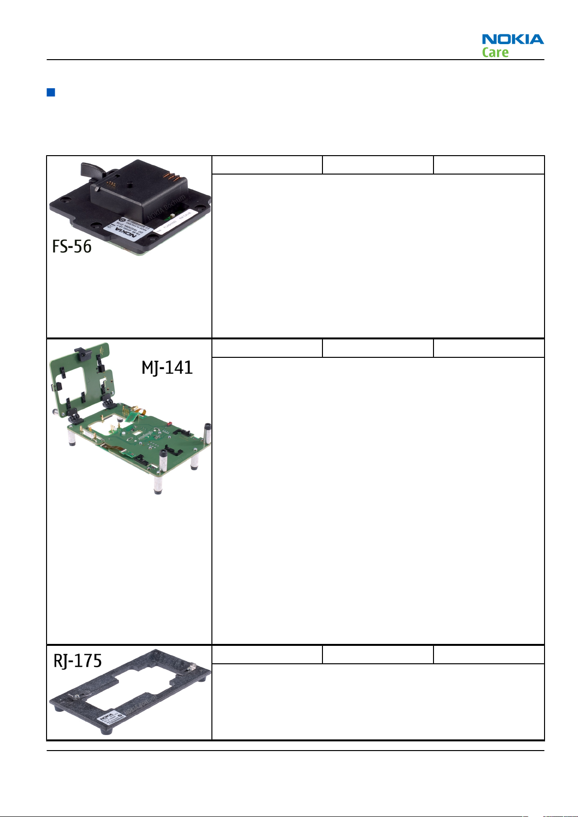
RJ-175 Soldering jig
RJ-175 is a soldering jig used for soldering and as a rework jig for the
engine module.
Issue 1 COMPANY CONFIDENTIAL Page 2 –5
Copyright © 2007 Nokia. All rights reserved.
Page 26
RM-244
Service Tools and Service Concepts
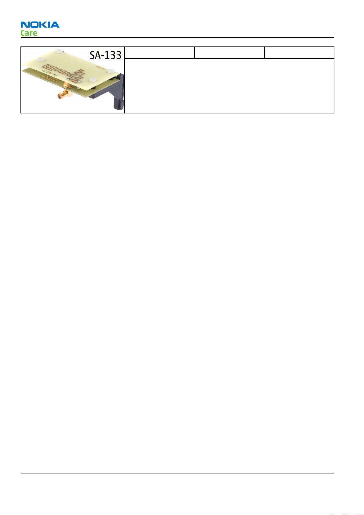
SA-133 RF coupler SA-133 is an RF coupler for WCDMA and GSM RF testing. It is used
together with the product-specific flash adapter.
General tools
The table below gives a short overview of service tools that can be used for testing, error analysis and repair
of product RM-244, refer to various concepts.
Page 2 –6 COMPANY CONFIDENTIAL Issue 1
Copyright © 2007 Nokia. All rights reserved.
Page 27
RM-244
Service Tools and Service Concepts
CU-4 Control unit CU-4 is a general service tool used with a module jig and/or a flash
adapter. It requires an external 12 V power supply.
The unit has the following features:
• software controlled via USB
• EM calibration function
• Forwards FBUS/Flashbus traffic to/from terminal
• Forwards USB traffic to/from terminal
• software controlled BSI values
• regulated VBATT voltage
• 2 x USB2.0 connector (Hub)
• FBUS and USB connections supported
When using CU-4, note the special order of connecting cables and
other service equipment:
Instructions
1 Connect a service tool (jig, flash adapter) to CU-4.
2 Connect CU-4 to your PC with a USB cable.
3 Connect supply voltage (12 V)
4 Connect an FBUS cable (if necessary).
5 Start Phoenix service software.
Note: Phoenix enables CU-4 regulators via USB when it is
started.
Reconnecting the power supply requires a Phoenix restart.
Issue 1 COMPANY CONFIDENTIAL Page 2 –7
Copyright © 2007 Nokia. All rights reserved.
Page 28
RM-244
Service Tools and Service Concepts
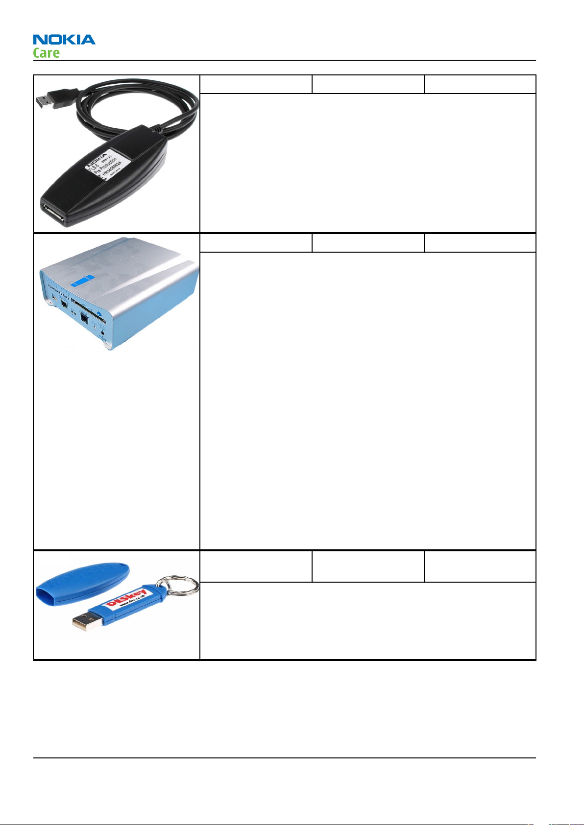
FLS-5 Flash device FLS-5 is a dongle and flash device incorporated into one package,
developed specifically for POS use.
Note: FLS-5 can be used as an alternative to PKD-1.
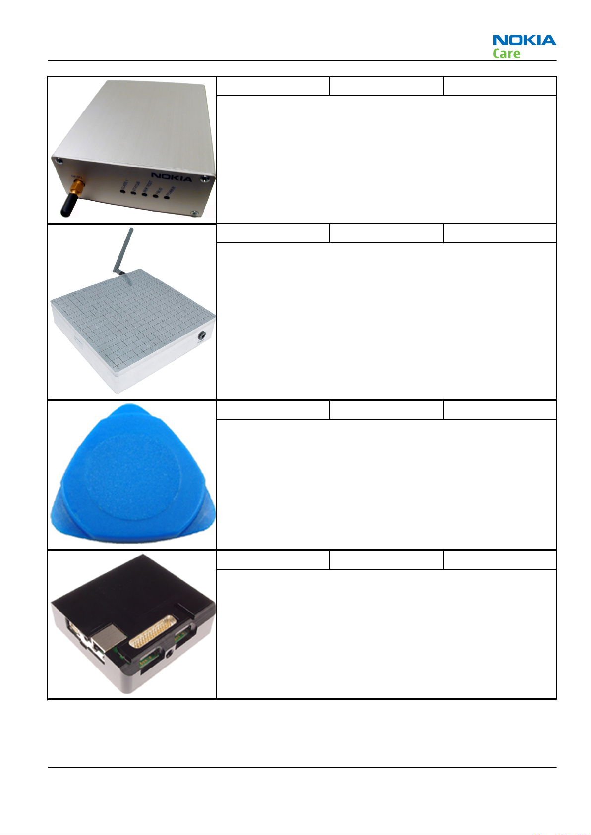
FPS-10 Flash prommer FPS-10 interfaces with:
• PC
• Control unit
• Flash adapter
• Smart card
FPS-10 flash prommer features:
• Flash functionality for BB5 and DCT-4 terminals
• Smart Card reader for SX-2 or SX-4
• USB traffic forwarding
• USB to FBUS/Flashbus conversion
• LAN to FBUS/Flashbus and USB conversion
• Vusb output switchable by PC command
FPS-10 sales package includes:
• FPS-10 prommer
• Power Supply with 5 country specific cords
• USB cable
Note: FPS-21 is substitute FPS-10 if FPS-10 has not been set
up.
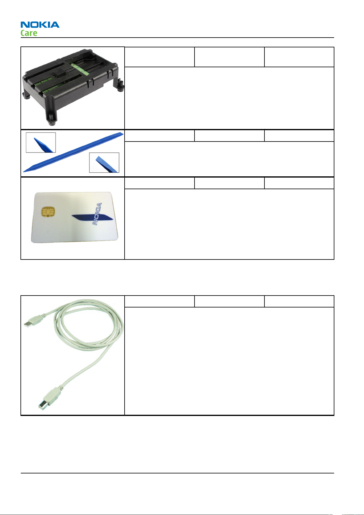
PK-1 Software protection
key
PK-1 is a hardware protection key with a USB interface. It has the same
functionality as the PKD-1 series dongle.
PK-1 is meant for use with a PC that does not have a series interface.
To use this USB dongle for security service functions please register
the dongle in the same way as the PKD-1 series dongle.
Page 2 –8 COMPANY CONFIDENTIAL Issue 1
Copyright © 2007 Nokia. All rights reserved.
Page 29
RM-244
Service Tools and Service Concepts
SB-6 Bluetooth tester The SB-6 test box is a generic device to perform Bluetooth bit error
rate testing and doing cordless FBUS connection via Bluetooth.
SB-7 WLAN test box WLAN test requires defined position for the device.
SRT-6 Opening tool SRT-6 is used to open phone covers.
SS-46 Interface adapter SS-46 acts as an interface adapter between the flash adapter and
FPS-10.
Issue 1 COMPANY CONFIDENTIAL Page 2 –9
Copyright © 2007 Nokia. All rights reserved.
Page 30
RM-244
Service Tools and Service Concepts
SS-62 Generic flash adapter
base for BB5
• generic base for flash adapters and couplers
• SS-62 equipped with a clip interlock system
• provides standardised interface towards Control Unit
• provides RF connection using galvanic connector or coupler
• multiplexing between USB and FBUS media, controlled by VUSB
SS-93 Opening tool SS-93 is used for opening JAE connectors.
SX-4 Smart card SX-4 is a BB5 security device used to protect critical features in tuning
and testing.
SX-4 is also needed together with FPS-10 when DCT-4 phones are
flashed.
Cables
The table below gives a short overview of service tools that can be used for testing, error analysis and repair
of product RM-244, refer to various concepts.
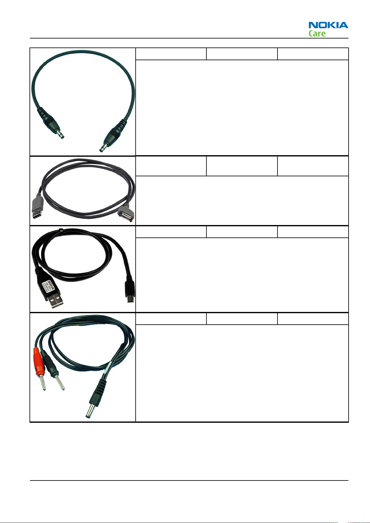
CA-31D USB cable The CA-31D USB cable is used to connect FPS-10 or FPS-11 to a PC. It is
included in the FPS-10 and FPS-11 sales packages.
Page 2 –10 COMPANY CONFIDENTIAL Issue 1
Copyright © 2007 Nokia. All rights reserved.
Page 31
RM-244
Service Tools and Service Concepts
CA-35S Power cable CA-35S is a power cable for connecting, for example, the FPS-10 flash
prommer to the Point-Of-Sales (POS) flash adapter.
CA-53 USB connectivity
cable
USB to system connector cable.
DKE-2 Mini-USB cable USB to mini-USB connector cable.
PCS-1 Power cable The PCS-1 power cable (DC) is used with a docking station, a module
jig or a control unit to supply a controlled voltage.
Issue 1 COMPANY CONFIDENTIAL Page 2 –11
Copyright © 2007 Nokia. All rights reserved.
Page 32

RM-244
Service Tools and Service Concepts
SS-102 Front camera
removal tool
The front camera removal tool SS-102 is used to remove/attach a front
camera module from/to the camera socket of the phone PWB.
XCS-4 Modular cable XCS-4 is a shielded (one specially shielded conductor) modular cable
for flashing and service purposes.
XRS-6 RF cable The RF cable is used to connect, for example, a module repair jig to
the RF measurement equipment.
SMA to N-Connector approximately 610 mm.
Attenuation for:
• GSM850/900: 0.3+-0.1 dB
• GSM1800/1900: 0.5+-0.1 dB
• WLAN: 0.6+-0.1dB
Page 2 –12 COMPANY CONFIDENTIAL Issue 1
Copyright © 2007 Nokia. All rights reserved.
Page 33

RM-244
Service Tools and Service Concepts
Service concepts
POS (Point of Sale) flash concept
Figure 2 POS flash concept
Type Description
Product specific tools
BP-6MT Battery
Other tools
FLS-5 POS flash dongle
PC with Phoenix service software
Cables
CA-53 USB connectivity cable
Issue 1 COMPANY CONFIDENTIAL Page 2 –13
Copyright © 2007 Nokia. All rights reserved.
Page 34

POS (Point of Sale) flash concept
RM-244
Service Tools and Service Concepts
Figure 3 POS flash concept
Type Description
Product specific tools
BP-6MT Battery
Other tools
FLS-5 POS flash dongle
PC with Phoenix service software
Cables
DKE-2 USB connectivity cable
Page 2 –14 COMPANY CONFIDENTIAL Issue 1
Copyright © 2007 Nokia. All rights reserved.
Page 35

RM-244
Service Tools and Service Concepts
Module jig service concept
Figure 4 Module jig service concept
Type Description
Phone specific devices
MJ-141 Module jig
Other devices
CU-4 Control unit
FPS-10 Flash prommer box
PK-1 SW security device
SX-4 Smart card
PC with VPOS and Phoenix service software
Measurement equipment
Cables
PCS-1 DC power cable
XCS-4 Modular cable
XRF-1 RF cable
USB cable
Issue 1 COMPANY CONFIDENTIAL Page 2 –15
Copyright © 2007 Nokia. All rights reserved.
Page 36
Type Description
GPIB control cable
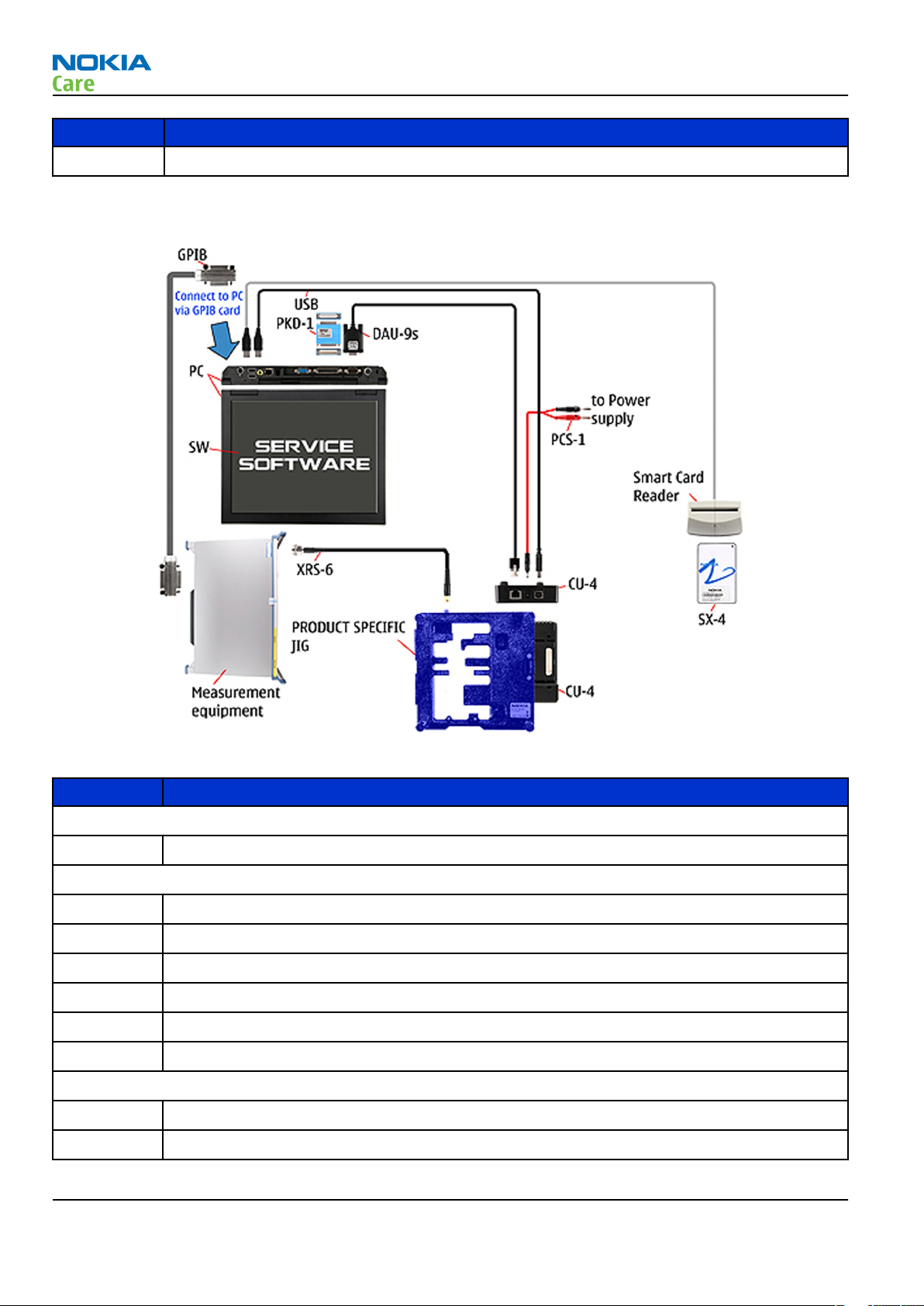
Service concept for RF testing and RF/BB tuning
RM-244
Service Tools and Service Concepts
Figure 5 Service concept for RF testing and RF/BB tuning
Type Description
Product specific devices
MJ-141 Module jig
Other devices
CU-4 Control unit
PK-1 SW security device
SX-4 Smart card
Measurement equipment
Smart card reader
PC with Phoenix service software
Cables
DAU-9S MBUS cable
PCS-1 DC power cable
Page 2 –16 COMPANY CONFIDENTIAL Issue 1
Copyright © 2007 Nokia. All rights reserved.
Page 37

RM-244
Service Tools and Service Concepts
Type Description
XRS-6 RF cable
GPIB control cable
USB cable
Flash concept with FPS-10
Figure 6 Basic flash concept with FPS-10
Type Description
Product specific devices
FS-56 Flash adapter
Other devices
FPS-10 Flash prommer box
PKD-1/PK-1 SW security device
SS-46 Interface adapter
PC with Phoenix service software
Cables
XCS-4 Modular cable
CA-35S Power cable
Issue 1 COMPANY CONFIDENTIAL Page 2 –17
Copyright © 2007 Nokia. All rights reserved.
Page 38

Type Description
USB cable
RF testing concept with RF coupler
RM-244
Service Tools and Service Concepts
Figure 7 RF testing concept with RF coupler
Type Description
Product specific devices
FS-56 Flash adapter
SA-133 RF coupler
Other devices
CU-4 Control unit
SX-4 Smart card
FPS-10 Flash prommer box
PKD-1/PK-1 SW security device
SS-62 Flash adapter base
Measurement equipment
PC with Phoenix service software
Cables
PCS-1 Power cable
Page 2 –18 COMPANY CONFIDENTIAL Issue 1
Copyright © 2007 Nokia. All rights reserved.
Page 39

RM-244
Service Tools and Service Concepts
Type Description
XCS-4 Modular cable
XRS-6 RF cable
GPIB control cable
USB cable
CU-4 flash concept with FPS-10
Figure 8 CU-4 flash concept with FPS-10
Type Description
Product specific devices
FS-56 Flash adapter
Other devices
CU-4 Control unit
FPS-10 Flash prommer box
PKD-1/PK-1 SW security device
SS-62 Flash adapter base
SX-4 Smart card
PC with Phoenix service software
Cables
Issue 1 COMPANY CONFIDENTIAL Page 2 –19
Copyright © 2007 Nokia. All rights reserved.
Page 40

Type Description
PCS-1 Power cable
XCS-4 Modular cable
Standard USB cable
USB cable
RM-244
Service Tools and Service Concepts
Page 2 –20 COMPANY CONFIDENTIAL Issue 1
Copyright © 2007 Nokia. All rights reserved.
Page 41

Nokia Customer Care
3 — BB Troubleshooting and
Manual Tuning Guide
Issue 1 COMPANY CONFIDENTIAL Page 3 –1
Copyright © 2007 Nokia. All rights reserved.
Page 42

RM-244
BB Troubleshooting and Manual Tuning Guide
(This page left intentionally blank.)
Page 3 –2 COMPANY CONFIDENTIAL Issue 1
Copyright © 2007 Nokia. All rights reserved.
Page 43

RM-244
BB Troubleshooting and Manual Tuning Guide
Table of Contents
Troubleshooting overview ....................................................................................................................................3–5
Dead or jammed device troubleshooting............................................................................................................3–6
General power checking ........................................................................................................................................3–7
Clocking troubleshooting ......................................................................................................................................3–9
Charging troubleshooting .................................................................................................................................. 3–10
Backup battery troubleshooting........................................................................................................................ 3–11
Flash programming fault troubleshooting....................................................................................................... 3–12
Combo memory troubleshooting ...................................................................................................................... 3–14
MicroSD card troubleshooting............................................................................................................................ 3–15
Mini USB interface troubleshooting................................................................................................................... 3–17
SIM card troubleshooting ................................................................................................................................... 3–18
Keyboard troubleshooting ................................................................................................................................. 3–20
Power key troubleshooting................................................................................................................................ 3–22
IrDA troubleshooting .......................................................................................................................................... 3–23
Vibra troubleshooting......................................................................................................................................... 3–24
Display module troubleshooting ....................................................................................................................... 3–25
General instructions for display troubleshooting....................................................................................... 3–25
Display troubleshooting ................................................................................................................................ 3–26
Display and keyboard backlight troubleshooting....................................................................................... 3–27
LED driver troubleshooting ........................................................................................................................... 3–29
Email LED troubleshooting............................................................................................................................ 3–30
ALS troubleshooting............................................................................................................................................ 3–31
Bluetooth troubleshooting................................................................................................................................. 3–32
Introduction to Bluetooth troubleshooting ................................................................................................ 3–32
Bluetooth settings for Phoenix..................................................................................................................... 3–32
Bluetooth self tests in Phoenix..................................................................................................................... 3–33
FM radio troubleshooting................................................................................................................................... 3–35
FM radio troubleshooting.............................................................................................................................. 3–35
WLAN troubleshooting........................................................................................................................................ 3–35
Introduction to WLAN troubleshooting ....................................................................................................... 3–35
WLAN functionality testing with self tests .................................................................................................. 3–35
WLAN functionality testing using SB-7 ........................................................................................................ 3–37
Audio troubleshooting........................................................................................................................................ 3–39
Audio troubleshooting test instructions...................................................................................................... 3–39
Internal earpiece troubleshooting ............................................................................................................... 3–42
Internal microphone troubleshooting......................................................................................................... 3–43
IHF speakers troubleshooting....................................................................................................................... 3–45
External headset microphone troubleshooting.......................................................................................... 3–46
External headset earpiece troubleshooting ................................................................................................ 3–47
Acoustics troubleshooting............................................................................................................................. 3–48
Introduction to acoustics troubleshooting ............................................................................................ 3–48
Earpiece troubleshooting......................................................................................................................... 3–49
IHF troubleshooting.................................................................................................................................. 3–50
Microphone troubleshooting ................................................................................................................... 3–51
Baseband manual tuning guide......................................................................................................................... 3–52
Certificate restoring for BB5 products.......................................................................................................... 3–52
Energy management calibration.................................................................................................................. 3–57
List of Tables
Issue 1 COMPANY CONFIDENTIAL Page 3 –3
Copyright © 2007 Nokia. All rights reserved.
Page 44

RM-244
BB Troubleshooting and Manual Tuning Guide
Table 10 Display module troubleshooting cases ............................................................................................. 3–25
Table 11 Pixel defects ......................................................................................................................................... 3–25
Table 12 Calibration value limits ....................................................................................................................... 3–57
List of Figures
Figure 9 Charging backup battery ..................................................................................................................... 3–11
Figure 10 Discharging backup battery .............................................................................................................. 3–11
Figure 11 Take single trig measurement for the rise of the BSI signal. ........................................................ 3–13
Figure 12 RM-244 Bluetooth antenna ............................................................................................................... 3–32
Figure 13 BER test result..................................................................................................................................... 3–33
Figure 14 Bluetooth self tests in Phoenix......................................................................................................... 3–34
Figure 15 Single-ended output waveform of the Ext_in_HP_out measurement when earpiece is
connected. ................................................................................................................................................. 3–40
Figure 16 Single-ended output waveform of the Ext_in_IHF_out loop measurement when speaker is
connected (measured at speaker pads). No filter is used. ................................................................... 3–41
Figure 17 Single-ended output waveform of the Ext_in_Ext_out loop........................................................... 3–41
Figure 18 Single-ended output waveform of the Digital_stereo_microphone_in_Ext_out loop.................. 3–41
Figure 19 Data out signal ................................................................................................................................... 3–44
Page 3 –4 COMPANY CONFIDENTIAL Issue 1
Copyright © 2007 Nokia. All rights reserved.
Page 45

RM-244
BB Troubleshooting and Manual Tuning Guide
Troubleshooting overview
For practical reasons, troubleshooting is divided into two sections;
• Baseband troubleshooting, including camera, FM radio and Bluetooth.
• RF troubleshooting
Issue 1 COMPANY CONFIDENTIAL Page 3 –5
Copyright © 2007 Nokia. All rights reserved.
Page 46

Dead or jammed device troubleshooting
Troubleshooting flow
RM-244
BB Troubleshooting and Manual Tuning Guide
Page 3 –6 COMPANY CONFIDENTIAL Issue 1
Copyright © 2007 Nokia. All rights reserved.
Page 47

RM-244
BB Troubleshooting and Manual Tuning Guide
General power checking
Check the following voltages:
Signal
name
VIO AVILMA ON ON 1.82 Memory,
VBACK AVILMA ON ON 2.5 Back-up
VSIM1 AVILMA ON ON 1.8/3.0 Sim card VBAT3
VSIM2 AVILMA ON ON Digital
VDRAM AVILMA ON ON 1.82 SDRAM VBAT2
VAUX AVILMA OFF OFF 2.78 FM radio,
VANA AVILMA ON ON 2.5 Avilma VBAT4
VR1 AVILMA OFF ON 2.5 Crystal VBAT4
Regulator Sleep Idle Nominal
voltage
Main user Notes Supply
VBAT1
I/Os
battery
VBAT3
micropho
ne
VBAT5
IrDA, MR
sensor,
display
oscillator
s
VRFC AVILMA ON OFF 1.8 RAPIDO
converter
s
VRCP1 AVILMA 4.75 To RF
parts
VRCP2 AVILMA 4.75 To RF
parts
VREF AVILMA ON ON 1.35 RF
reference
VCORE BarracudaON ON 1.35/!.05
on sleep)
VOUT BETTY OFF OFF 2.5 Audio
VAUX External
LDO
VDIG_CAM External
SMPS
2.8 Camera
1.8 Camera
Rapido
digital
core
switch,
ALS
and
STV984
RF active VBATCP
RF active VBATCP
VBAT6
Issue 1 COMPANY CONFIDENTIAL Page 3 –7
Copyright © 2007 Nokia. All rights reserved.
Page 48

RM-244
BB Troubleshooting and Manual Tuning Guide
Signal
name
VLED External
VSD SD
VIO External
Regulator Sleep Idle Nominal
SMPS
levelsifter
LDO
Main user Notes Supply
voltage
14 Display
backlight
2.85 Micro SD
card
ON ON 1.8 Display
Page 3 –8 COMPANY CONFIDENTIAL Issue 1
Copyright © 2007 Nokia. All rights reserved.
Page 49

RM-244
BB Troubleshooting and Manual Tuning Guide
Clocking troubleshooting
Troubleshooting flow
Issue 1 COMPANY CONFIDENTIAL Page 3 –9
Copyright © 2007 Nokia. All rights reserved.
Page 50

Charging troubleshooting
Troubleshooting flow
RM-244
BB Troubleshooting and Manual Tuning Guide
Page 3 –10 COMPANY CONFIDENTIAL Issue 1
Copyright © 2007 Nokia. All rights reserved.
Page 51

RM-244
BB Troubleshooting and Manual Tuning Guide
Backup battery troubleshooting
Verify that the backup battery is empty (U<1V). Switch the phone on. Measure voltage of the battery when
the main battery is connected to the phone and the phone is switched on.
Wait a few minutes and monitor that the backup battery voltage rises. Switch off the phone, disconnect the
main battery and monitor that the voltage of the backup battery decreases. Normal behaviour of the voltage
is described in the figures below.
Figure 9 Charging backup battery
Figure 10 Discharging backup battery
If the voltage rises and falls quickly, check whether G2200, C2238 or C2245 is broken or short-circuited. Backup
battery can be also dead. If the voltage stays ~0V, check resistance VBACK against GND. If there is no shortcircuit, AVILMA is faulty. Replace AVILMA.
Issue 1 COMPANY CONFIDENTIAL Page 3 –11
Copyright © 2007 Nokia. All rights reserved.
Page 52

Flash programming fault troubleshooting
Part 1
RM-244
BB Troubleshooting and Manual Tuning Guide
Page 3 –12 COMPANY CONFIDENTIAL Issue 1
Copyright © 2007 Nokia. All rights reserved.
Page 53

RM-244
BB Troubleshooting and Manual Tuning Guide
Part 2
Figure 11 Take single trig measurement for the rise of the BSI signal.
Issue 1 COMPANY CONFIDENTIAL Page 3 –13
Copyright © 2007 Nokia. All rights reserved.
Page 54

Combo memory troubleshooting
Troubleshooting flow
RM-244
BB Troubleshooting and Manual Tuning Guide
Page 3 –14 COMPANY CONFIDENTIAL Issue 1
Copyright © 2007 Nokia. All rights reserved.
Page 55

RM-244
BB Troubleshooting and Manual Tuning Guide
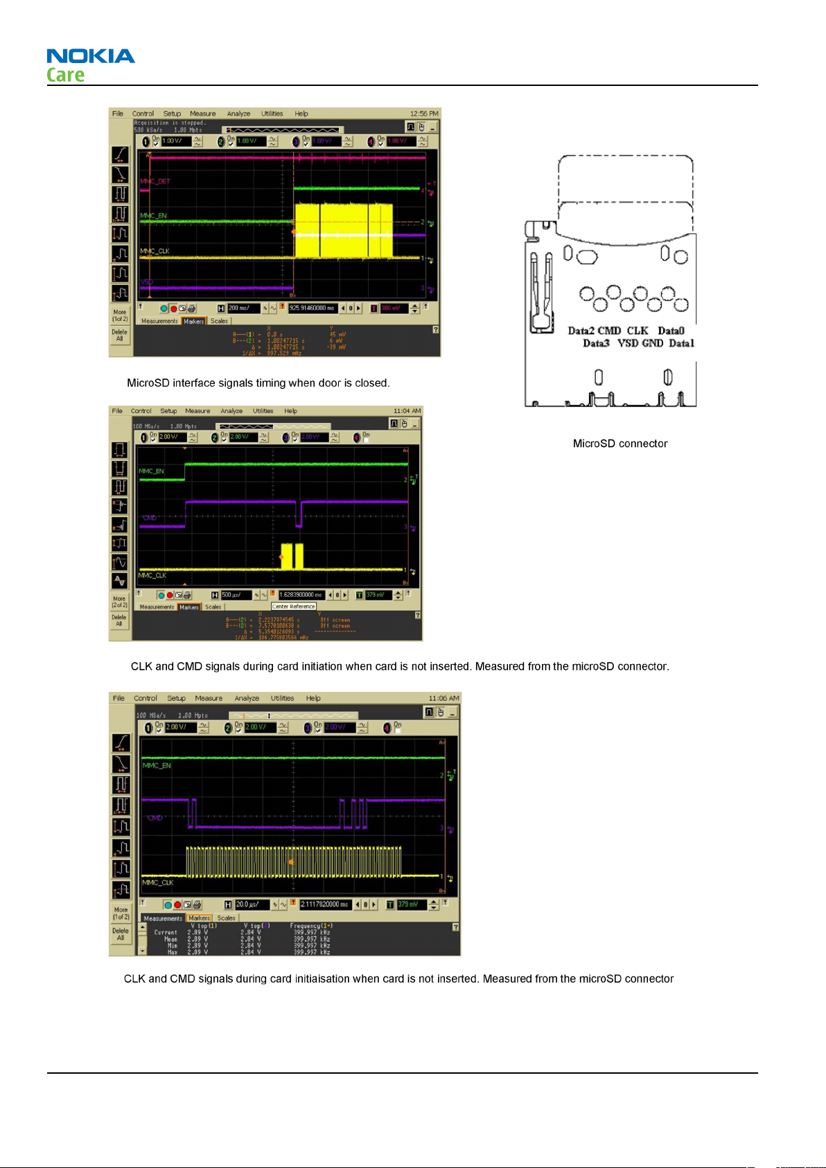
MicroSD card troubleshooting
Troubleshooting flow
Issue 1 COMPANY CONFIDENTIAL Page 3 –15
Copyright © 2007 Nokia. All rights reserved.
Page 56
RM-244
BB Troubleshooting and Manual Tuning Guide
Page 3 –16 COMPANY CONFIDENTIAL Issue 1
Copyright © 2007 Nokia. All rights reserved.
Page 57

RM-244
BB Troubleshooting and Manual Tuning Guide
Mini USB interface troubleshooting
Troubleshooting flow
Issue 1 COMPANY CONFIDENTIAL Page 3 –17
Copyright © 2007 Nokia. All rights reserved.
Page 58

SIM card troubleshooting
Troubleshooting flow
RM-244
BB Troubleshooting and Manual Tuning Guide
Page 3 –18 COMPANY CONFIDENTIAL Issue 1
Copyright © 2007 Nokia. All rights reserved.
Page 59

RM-244
BB Troubleshooting and Manual Tuning Guide
Issue 1 COMPANY CONFIDENTIAL Page 3 –19
Copyright © 2007 Nokia. All rights reserved.
Page 60

RM-244
BB Troubleshooting and Manual Tuning Guide
Keyboard troubleshooting
Context
There are two possible failure modes in the keyboard module:
• One or more keys can be stuck, so that the key does not react when a keydome is pressed. This kind of
failure is caused by mechanical reasons (dirt, rust).
• Malfunction of several keys at the same time; this happens when one or more rows or columns are failing
(shortcut or open connection). For a more detailed description of the keyboard and keymatrix, see section
Keyboard.
If the failure mode is not clear, start with the Keyboard Test in Phoenix.
Page 3 –20 COMPANY CONFIDENTIAL Issue 1
Copyright © 2007 Nokia. All rights reserved.
Page 61

RM-244
BB Troubleshooting and Manual Tuning Guide
Troubleshooting flow
Issue 1 COMPANY CONFIDENTIAL Page 3 –21
Copyright © 2007 Nokia. All rights reserved.
Page 62

Power key troubleshooting
Troubleshooting flow
RM-244
BB Troubleshooting and Manual Tuning Guide
Page 3 –22 COMPANY CONFIDENTIAL Issue 1
Copyright © 2007 Nokia. All rights reserved.
Page 63
RM-244
BB Troubleshooting and Manual Tuning Guide
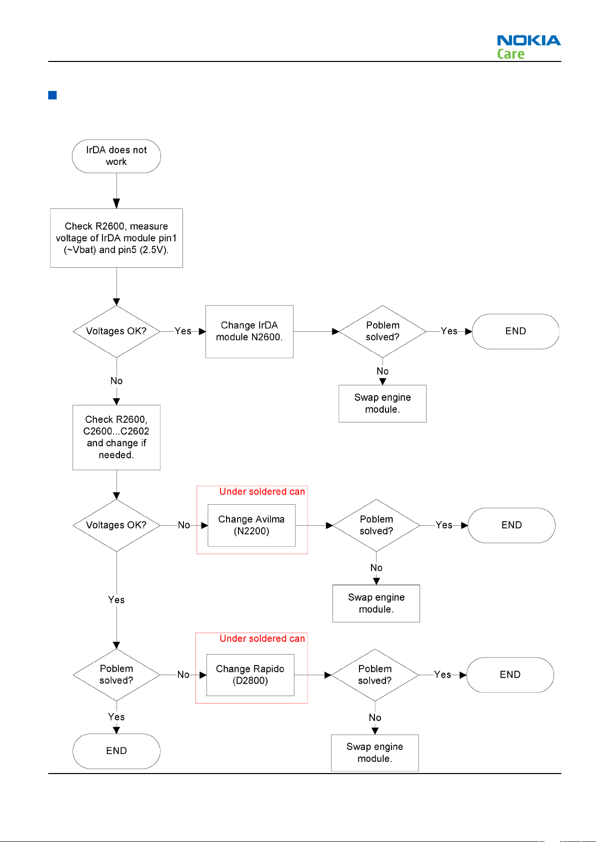
IrDA troubleshooting
Troubleshooting flow
Issue 1 COMPANY CONFIDENTIAL Page 3 –23
Copyright © 2007 Nokia. All rights reserved.
Page 64

Vibra troubleshooting
Troubleshooting flow
RM-244
BB Troubleshooting and Manual Tuning Guide
Page 3 –24 COMPANY CONFIDENTIAL Issue 1
Copyright © 2007 Nokia. All rights reserved.
Page 65
RM-244
BB Troubleshooting and Manual Tuning Guide
Display module troubleshooting
General instructions for display troubleshooting
Context
• The display is in a normal mode when the phone is in active use.
• Display is in a partial idle mode when the phone is in the screen saver mode.
• The operating modes of the display can be controlled with the help of
Table 10 Display module troubleshooting cases
Display blank There is no image on the display. The display looks
the same when the phone is on as it does when the
phone is off. The backlight can be on in some cases.
Image on the display not correct Image on the display can be corrupted or a part of
the image can be missing. If a part of the image is
missing, change the display module. If the image is
otherwise corrupted, follow the appropriate
troubleshooting diagram.
Phoenix
.
Backlight dim or not working at all Backlight LED components are inside the display
module. Backlight failure can also be in the
connector or in the backlight power source in the
main engine of the phone.
This means that in case the display is working
(image OK), the backlight is faulty.
Visual defects (pixel) Pixel defects can be checked by controlling the
display with Phoenix. Use both colours, black and
white, on a full screen.
The display may have some random pixel defects
that are acceptable for this type of display. The
criteria when pixel defects are regarded as a display
failure, resulting in a replacement of the display, are
presented the following table.
Table 11 Pixel defects
Item White dot defect Black dot
defect
1 Defect counts R G B White Dot
Total
1 1
Total
1 1 1 1
2 Combined
defect counts
Issue 1 COMPANY CONFIDENTIAL Page 3 –25
Not allowed.
Two single dot defects that are within 5 mm of each other should be
interpreted as combined dot defect.
Copyright © 2007 Nokia. All rights reserved.
Page 66

RM-244
BB Troubleshooting and Manual Tuning Guide
Steps
1. Verify with a working display that the fault is not on the display module itself.
The display module cannot be repaired.
2. Check that the cellular engine is working normally.
i To check the functionality, connect the phone to a docking station.
ii Start
iii Read the phone information to check that also the application engine is functioning normally (you
3. Proceed to the display troubleshooting flowcharts.
Use the Display Test tool in
Phoenix
should be able to read the APE ID).
service software.
Phoenix
to find the detailed fault mode.
Display troubleshooting
Context
Before going to display troubleshooting flow, make sure that the engine is working and starting up correctly.
If the problem is in the engine, go to baseband troubleshooting.
Page 3 –26 COMPANY CONFIDENTIAL Issue 1
Copyright © 2007 Nokia. All rights reserved.
Page 67

RM-244
BB Troubleshooting and Manual Tuning Guide
Troubleshooting flow
Issue 1 COMPANY CONFIDENTIAL Page 3 –27
Copyright © 2007 Nokia. All rights reserved.
Page 68

Display and keyboard backlight troubleshooting
Troubleshooting flow
RM-244
BB Troubleshooting and Manual Tuning Guide
Page 3 –28 COMPANY CONFIDENTIAL Issue 1
Copyright © 2007 Nokia. All rights reserved.
Page 69

RM-244
BB Troubleshooting and Manual Tuning Guide
LED driver troubleshooting
Troubleshooting flow
Issue 1 COMPANY CONFIDENTIAL Page 3 –29
Copyright © 2007 Nokia. All rights reserved.
Page 70

Email LED troubleshooting
Troubleshooting flow
RM-244
BB Troubleshooting and Manual Tuning Guide
Page 3 –30 COMPANY CONFIDENTIAL Issue 1
Copyright © 2007 Nokia. All rights reserved.
Page 71

RM-244
BB Troubleshooting and Manual Tuning Guide
ALS troubleshooting
Troubleshooting flow
Issue 1 COMPANY CONFIDENTIAL Page 3 –31
Copyright © 2007 Nokia. All rights reserved.
Page 72

BB Troubleshooting and Manual Tuning Guide
Bluetooth troubleshooting
Introduction to Bluetooth troubleshooting
There are two main Bluetooth problems that can occur:
Problem Description
Detachment of the BT antenna. This would most likely happen if the device has
been dropped repeatedly to the ground. It could
cause the BT antenna to become loose or partially
detached from the PWB.
RM-244
A malfunction in the BT ASIC, BB ASICs or Phone’s BT
SMD components.
The main issue is to find out if the problem is related to the BT antenna or related to the BT system or the
phone’s BB and then replace/fix the faulty component.
This is unpredictable and could have many causes
i.e. SW or HW related.
Bluetooth antenna
Figure 12 RM-244 Bluetooth antenna
Bluetooth settings for Phoenix
Steps
1. Start
2. From the File menu, choose Open Product, and then choose the correct type designator from the
3. Place the phone to a flash adapter in the local mode.
4. Choose Testing→Bluetooth LOCALS .
Page 3 –32 COMPANY CONFIDENTIAL Issue 1
Phoenix
Product list.
service software.
Copyright © 2007 Nokia. All rights reserved.
Page 73

RM-244
BB Troubleshooting and Manual Tuning Guide
5. Locate SB-6’s serial number (12 digits) found in the type label on the back of SB-6.
In addition to SB-6 , also JBT-3, JBT-6 and JBT-9 Bluetooth test boxes can be used.
6. In the
Counterpart BT Device Address line.
This needs to be done only once provided that SB-6 is not changed.
7. Place the SB-6 box near (within 10 cm) the BT antenna and click Run BER Test.
Bluetooth LOCALS
window, write the 12-digit serial number on the
Results
Bit Error Rate test result is displayed in the
Bit Error Rate (BER) Tests
pane in the
Bluetooth LOCALS
window.
Figure 13 BER test result
Bluetooth self tests in Phoenix
Steps
1. Start
2. ChooseFile→Scan Product.
3. Place the phone to a flash adapter.
4. From the Mode drop-down menu, set mode to Local.
5. Choose Testing→Self Tests.
6. In the
Issue 1 COMPANY CONFIDENTIAL Page 3 –33
Phoenix
Self Tests
• ST_LPRF_IF_TEST
service software.
window check the following Bluetooth related tests:
Copyright © 2007 Nokia. All rights reserved.
Page 74

• ST_LPRF_AUDIO_LINES_TEST
• ST_BT_WAKEUP_TEST
7. To run the tests, click Start.
RM-244
BB Troubleshooting and Manual Tuning Guide
Figure 14 Bluetooth self tests in
Phoenix
Page 3 –34 COMPANY CONFIDENTIAL Issue 1
Copyright © 2007 Nokia. All rights reserved.
Page 75

RM-244
BB Troubleshooting and Manual Tuning Guide
FM radio troubleshooting
FM radio troubleshooting
Troubleshooting flow
WLAN troubleshooting
Introduction to WLAN troubleshooting
The main problem that can occur is malfunction in WLAN ASICs, WLAN SMD or Antenna components. Such
problems are unpredictable and may have many causes, either HW or SW related.
WLAN functionality testing with self tests
Steps
1. Start Phoenix service software.
2. Choose File => Scan Product.
3. From the Mode drop-down menu, set mode to Local.
Issue 1 COMPANY CONFIDENTIAL Page 3 –35
Copyright © 2007 Nokia. All rights reserved.
Page 76

RM-244
BB Troubleshooting and Manual Tuning Guide
4. Choose Testing => Self Tests.
5. In the Self Tests window select the following WLAN related tests:
• ST_WLAN_TEST
• ST_BT_WLAN_COEXISTENCE_TEST
6. Press Start and after few seconds results should appear and if WLAN engine is functional, results should
show Passed. If one of the tests is Failed then there is something broken inside the WLAN module.
Page 3 –36 COMPANY CONFIDENTIAL Issue 1
Copyright © 2007 Nokia. All rights reserved.
Page 77

RM-244
BB Troubleshooting and Manual Tuning Guide
WLAN functionality testing using SB-7
Steps
1. Place the phone on the SB-7 WLAN test box, (see figure).
2. Start the phone to the normal mode.
3. Specify AP for the WLAN AP inside the SB-7: go to the Application – Tools – Settings – Connection –
Access points -menu. Select Options and then select New access point and then set the following
information:
a Connection name: default
b Data bearer: Wireless LAN
c WLAN network name: default
d Network status: Public
e WLAN network mode: Infrastructure
f WLAN security mode: Open network
g WLAN security settings: leave it as it is
h Homepage: 192.168.0.51
Issue 1 COMPANY CONFIDENTIAL Page 3 –37
Copyright © 2007 Nokia. All rights reserved.
Page 78

RM-244
BB Troubleshooting and Manual Tuning Guide
4. Go back to the top level by pressing Back – Back – Exit – Back – Exit.
5. Go to the Application –menu and select Web.
6. Open the Options –menu and select Settings and General.
a Define Access point – User defined and select Default from the pop-up menu.
b Define Homepage – User defined and enter 192.168.0.51.
7. Go back to the top level by pressing Back – Back – Exit – Exit.
8. Go to the Application –menu and select Web. Ignore the error message: Web, no gateway reply - this
is due to the fact that SB-7 is not connected to the internet.
9. Press Application button until you can select Standby.
10. Go to the Application –menu and select Connectivity – Conn.mgr. and select Active data
connections. Now you should see the connection named default and below the name there should be
time running. Or if you came very fast to this menu after turning browser on, there may be indication
of connecting below the name default. If so, wait until time starts to run below the name default.
Select these connections from the Options –menu by selecting Details.
a Status should show: Conn. (inactive… or Conn. (active).
b Signal should show: Medium (50%). This field can also be Strong and percent number can also be
higher.
11. WiFi indicator top of the screen should be ON when connected to the AP
12. If connection does not work, check the phone's WLAN / BT –antenna and matching components. See
figure below.
Page 3 –38 COMPANY CONFIDENTIAL Issue 1
Copyright © 2007 Nokia. All rights reserved.
Page 79

RM-244
BB Troubleshooting and Manual Tuning Guide
Audio troubleshooting
Audio troubleshooting test instructions
Single-ended external earpiece and differential internal earpiece outputs can be measured either with a
single-ended or a differential probe.
When measuring with a single-ended probe each output is measured against the ground.
Internal handsfree output is measured using a current probe, if a special low-pass filter designed for
measuring a digital amplifier is not available. Note also that when using a current probe, the input signal
frequency must be set to 2kHz.
The input signal for each loop test can be either single-ended or differential. Exception to this is a digital
microphone, which needs input signal from an external sound source (laptop speaker) to playback eg. 1kHz
sine wave from 5cm distance.
Required equipment
The following equipment is needed for the tests:
• Oscilloscope
• Function generator (sine waveform)
• Current probe (Internal handsfree PWM output measurement)
• Phoenix service software
• Battery voltage 3.7V
• Sound source (laptop speaker or B&K type 4231 calibrator)
Test procedure
Audio can be tested using the Phoenix audio routings option. Three different audio loop paths can be
activated:
• External microphone to Internal earpiece
• External microphone to Internal handsfree speaker
• Digital stereo microphone to External earpiece
Each audio loop sets routing from the specified input to the specified output enabling a quick in-out test.
Loop path gains are fixed and they cannot be changed using Phoenix. Correct pins and signals for each test
are presented in the following table.
Phoenix audio loop tests and test results
The results presented in the table apply when no accessory is connected and battery voltage is set to 3.7V.
Earpiece, internal microphone and speaker are in place during measurement. Applying a headset accessory
during measurement causes a significant drop in measured quantities.
The gain values presented in the table apply for a differential output vs. single-ended/differential input.
Issue 1 COMPANY CONFIDENTIAL Page 3 –39
Copyright © 2007 Nokia. All rights reserved.
Page 80

RM-244
BB Troubleshooting and Manual Tuning Guide
Loop test Input
terminal
External Mic to
External
Earpiece
External Mic to
Internal
Earpiece
External Mic to
Internal
handsfree
Digital Mic to
External
Earpiece
HS_MIC &
GND
HS_MIC &
GND
HS_MIC &
GND
Acoustical
input, 1kHz
sine wave
Output
terminal
HS_EAR_L &
GND
HS_EAR_R &
GND
EarP & GND -10 1000 310 1.2 NA
EarN & GND
J2103 &
J2104
J2101 &
J2102
HS_EAR_L &
GND
HS_EAR_R &
GND
Path
gain
[dB]
(fixed)
-8.6 1000 367 1.2 NA
-6 1000
NA 94 dB
Input
voltage
[mVp-
p]
SPL
Output
voltage
[mVp-p]
100 NA
Output
DC level
[V]
current [mA]
Output
Measurement data
Earpiece signal
Figure 15 Single-ended output waveform of the Ext_in_HP_out measurement when earpiece is connected.
Integrated handsfree signal
Page 3 –40 COMPANY CONFIDENTIAL Issue 1
Copyright © 2007 Nokia. All rights reserved.
Page 81

RM-244
BB Troubleshooting and Manual Tuning Guide
Figure 16 Single-ended output waveform of the Ext_in_IHF_out loop measurement when speaker is connected (measured
at speaker pads). No filter is used.
External output from AV
Figure 17 Single-ended output waveform of the Ext_in_Ext_out loop.
External output from AV (acoustic input)
Figure 18 Single-ended output waveform of the Digital_stereo_microphone_in_Ext_out loop.
Issue 1 COMPANY CONFIDENTIAL Page 3 –41
Copyright © 2007 Nokia. All rights reserved.
Page 82

Internal earpiece troubleshooting
Troubleshooting flow
RM-244
BB Troubleshooting and Manual Tuning Guide
Page 3 –42 COMPANY CONFIDENTIAL Issue 1
Copyright © 2007 Nokia. All rights reserved.
Page 83

RM-244
BB Troubleshooting and Manual Tuning Guide
Internal microphone troubleshooting
Troubleshooting flow
Issue 1 COMPANY CONFIDENTIAL Page 3 –43
Copyright © 2007 Nokia. All rights reserved.
Page 84

BB Troubleshooting and Manual Tuning Guide
Figure 19 Data out signal
RM-244
Page 3 –44 COMPANY CONFIDENTIAL Issue 1
Copyright © 2007 Nokia. All rights reserved.
Page 85

RM-244
BB Troubleshooting and Manual Tuning Guide
IHF speakers troubleshooting
Troubleshooting flow
Issue 1 COMPANY CONFIDENTIAL Page 3 –45
Copyright © 2007 Nokia. All rights reserved.
Page 86

External headset microphone troubleshooting
Troubleshooting flow
RM-244
BB Troubleshooting and Manual Tuning Guide
Page 3 –46 COMPANY CONFIDENTIAL Issue 1
Copyright © 2007 Nokia. All rights reserved.
Page 87

RM-244
BB Troubleshooting and Manual Tuning Guide
External headset earpiece troubleshooting
Troubleshooting flow
Issue 1 COMPANY CONFIDENTIAL Page 3 –47
Copyright © 2007 Nokia. All rights reserved.
Page 88

RM-244
BB Troubleshooting and Manual Tuning Guide
Acoustics troubleshooting
Introduction to acoustics troubleshooting
Acoustics design ensures that the sound is detected correctly with a microphone and properly radiated to
the outside of the device by speaker(s). The acoustics of the phone includes three basic systems: earpiece,
Integrated Hands Free (IHF) and microphone.
The sound reproduced from the earpiece readiates through a single hole on the front cover (A-cover). The
sound reproduced from the IHF speakers radiates from left and right sound holes located on both sides of
the device. Microphone is located at the bottom, next to the system connector.
For a correct functionality of the phone, all sound holes must be always open. When the phone is used, care
must be taken not to close any of those holes with a hand or fingers. The phone should be dry and clean,
and no objects must be located in such a way that they close any of the holes.
Page 3 –48 COMPANY CONFIDENTIAL Issue 1
Copyright © 2007 Nokia. All rights reserved.
Page 89

RM-244
BB Troubleshooting and Manual Tuning Guide
Earpiece troubleshooting
Troubleshooting flow
Issue 1 COMPANY CONFIDENTIAL Page 3 –49
Copyright © 2007 Nokia. All rights reserved.
Page 90

IHF troubleshooting
Troubleshooting flow
RM-244
BB Troubleshooting and Manual Tuning Guide
Page 3 –50 COMPANY CONFIDENTIAL Issue 1
Copyright © 2007 Nokia. All rights reserved.
Page 91

RM-244
BB Troubleshooting and Manual Tuning Guide
Microphone troubleshooting
Troubleshooting flow
Issue 1 COMPANY CONFIDENTIAL Page 3 –51
Copyright © 2007 Nokia. All rights reserved.
Page 92

BB Troubleshooting and Manual Tuning Guide
Baseband manual tuning guide
Certificate restoring for BB5 products
Context
This procedure is performed when the device certificate is corrupted for some reason.
All tunings (RF & Baseband, UI) must be done after performing the certificate restoring procedure.
The procedure for certificate restoring is the following:
• Flash the phone with the latest available software using FPS-8 or FPS-10.
Note: USB flashing does not work for a dead BB5 phone.
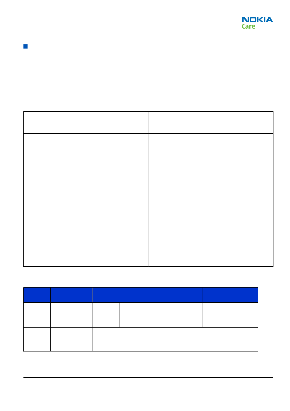
• Create a request file.
• Send the file to Nokia by e-mail. Use the following addresses depending on your location:
• APAC: sydney.service@nokia.com
• CHINA: repair.ams@nokia.com
• E&A: salo.repair@nokia.com
• AMERICAS: fls1.usa@nokia.com
• When you receive a reply from Nokia, carry out certificate restoring.
• Tune the phone completely.
Note: SX-4 smart card is needed.
• If the phone resets after certificate restoring, reflash the phone again.
Required equipment and setup:
•
Phoenix
• The latest phone model specific
• PKD-1 dongle
• SX-4 smart card (Enables BB5 testing and tuning features)
• External smart card reader
• Activated FPS-8 flash prommer OR FPS-10 flash prommer
• Flash update package 03.18.004 or newer for FPS-8 or FPS-10 flash prommers
• CU-4 control unit
• USB cable from PC USB Port to CU-4 control unit
• Phone model specific adapter for CU-4 control unit
• PCS-1 cable to power CU-4 from external power supply
• XCS-4 modular cable between flash prommer and CU-4
service software v 2007.19 or newer.
Phoenix
Note: The smart card reader is only needed when FPS-8 is used. FPS-10 has an integrated smart card
reader.
Note: CU-4 must be supplied with +12 V from an external power supply in all steps of certificate
restoring.
data package.
RM-244
Steps
1. Program the phone software.
i Start
Page 3 –52 COMPANY CONFIDENTIAL Issue 1
Phoenix
and login. Make sure the connection has been managed correctly for FPS-8 or FPS-10.
Copyright © 2007 Nokia. All rights reserved.
Page 93

RM-244
BB Troubleshooting and Manual Tuning Guide
ii Update the phone MCU software to the latest available version.
If the new flash is empty and the phone cannot communicate with
iii Choose the product manually from File→Open Product , and click OK.
Wait for the phone type designator (e.g. “RM-1” ) to be displayed in the status bar.
iv Go to Flashing→SW Update and wait until
picture.
Phoenix
reads the product data as shown in the following
Phoenix
, reflash the phone.
Product is automatically set according to the phone support module which was opened manually,
but the flash files cannot be found because the correct data cannot be read from the phone
automatically.
Code must be chosen manually, it determines the correct flash files to be used. Please choose the
correct product code (can be seen in the phone type label) from the dropdown list.
Flash Type must be set to Phone as Manufactured.
v To continue, click Start.
Progress bars and messages on the screen show actions during phone programming, please wait.
Issue 1 COMPANY CONFIDENTIAL Page 3 –53
Copyright © 2007 Nokia. All rights reserved.
Page 94

RM-244
BB Troubleshooting and Manual Tuning Guide
Programming is completed when
The product type designator and MCU SW version are displayed in the status bar.
vi Close the
2. Create a
For this procedure, you must supply +12 V to CU-4 from an external power supply.
i To connect the phone with
ii Choose Tools→Certificate Restore .
iii To choose a location for the request file, click Browse.
SW Update
Request
window and then choose File→Close Product .
file.
Phoenix
Flashing Completed
, choose File→Scan Product .
message is displayed.
Page 3 –54 COMPANY CONFIDENTIAL Issue 1
Copyright © 2007 Nokia. All rights reserved.
Page 95
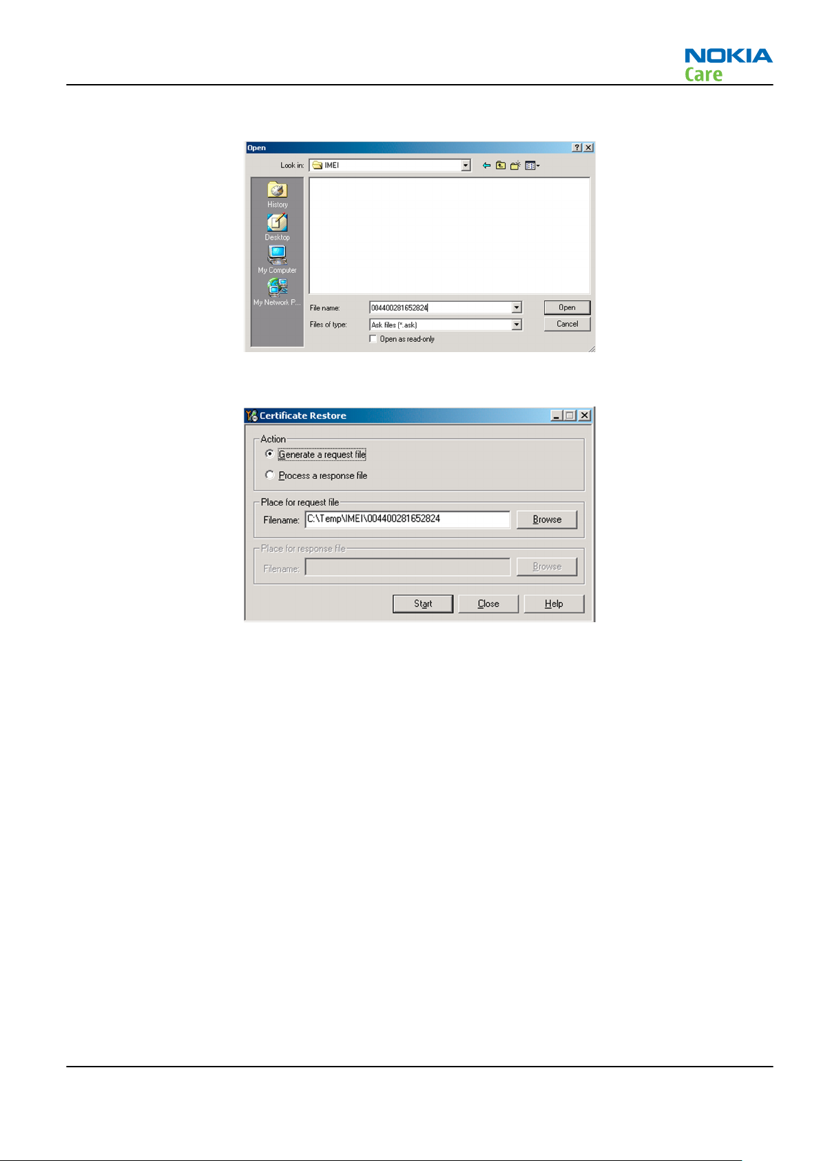
RM-244
BB Troubleshooting and Manual Tuning Guide
iv Name the file so that you can easily identify it, and click Open.
The name of the file and its location are shown.
v To create the
vi When the file for certificate restore has been created, send it to Nokia as an e-mail attachment.
3. Restore certificate.
For this procedure, you must supply +12 V to CU-4 from an external power supply.
i Save the reply file sent by Nokia to your computer.
ii Start
iii Choose File→Scan Product .
Phoenix
Request
service software.
file, click Start.
Issue 1 COMPANY CONFIDENTIAL Page 3 –55
Copyright © 2007 Nokia. All rights reserved.
Page 96
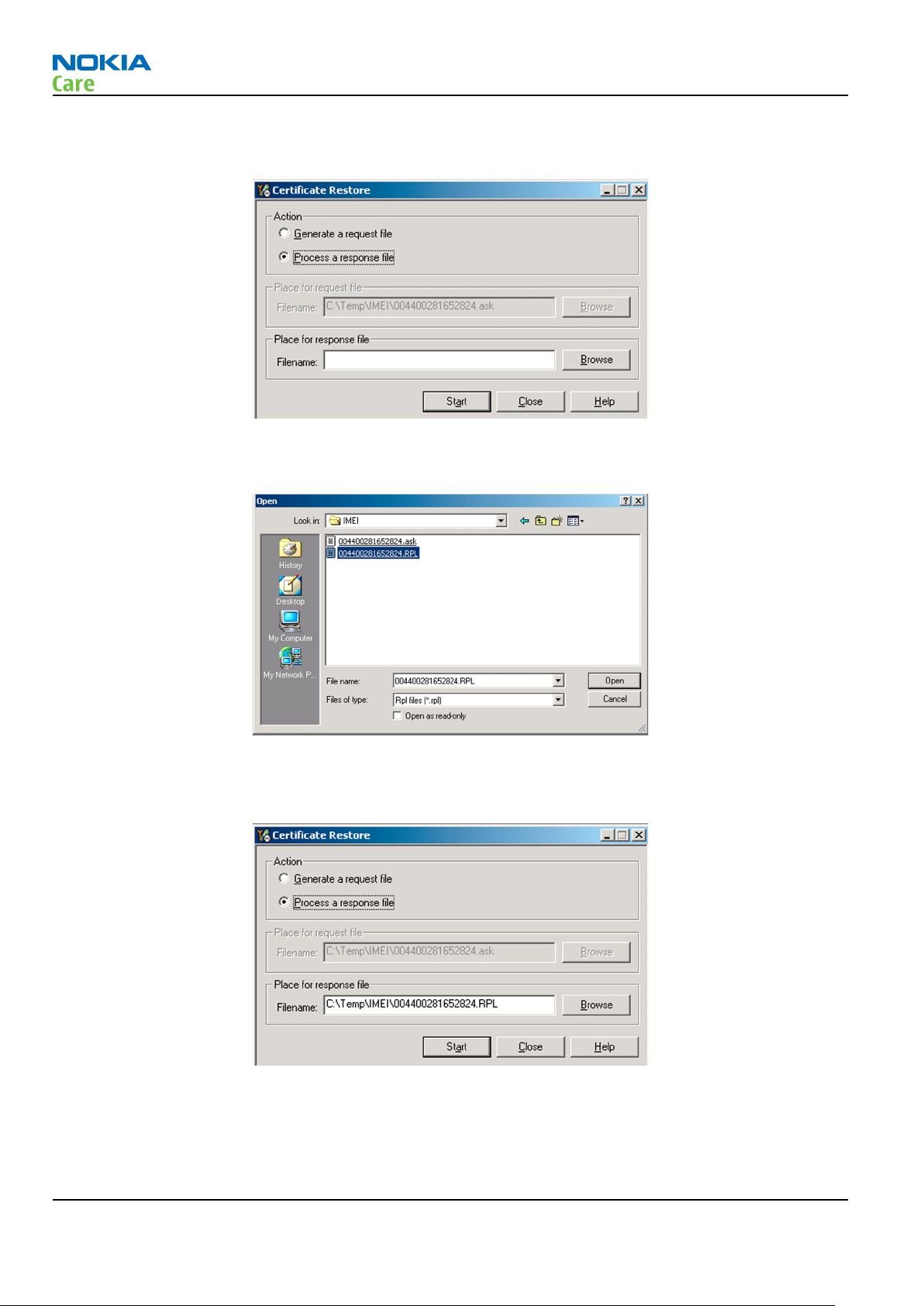
RM-244
BB Troubleshooting and Manual Tuning Guide
iv From the Tools menu, choose Certificate Restore and select Process a response file in the
pane.
v To choose the location where response file is saved, click Browse.
vi Click Open.
Action
The name of the file and the path where it is located are shown.
vii To write the file to phone, click Start.
Next actions
After a successful rewrite, you must retune the phone completely by using
Important: Perform all tunings: RF, BB, and UI.
Page 3 –56 COMPANY CONFIDENTIAL Issue 1
Copyright © 2007 Nokia. All rights reserved.
Phoenix
tuning functions.
Page 97

RM-244
BB Troubleshooting and Manual Tuning Guide
Energy management calibration
Prerequisites
Energy Management (EM) calibration is performed to calibrate the setting (gain and offset) of AD converters
in several channels (that is, battery voltage, BSI, battery current) to get an accurate AD conversion result.
Hardware setup:
• An external power supply is needed.
• Supply 12V DC from an external power supply to CU-4 to power up the phone.
• The phone must be connected to a CU-4 control unit with a product-specific flash adapter.
Steps
1. Place the phone to the docking station adapter (CU-4 is connected to the adapter).
2. Start
3. Choose File→ Scan Product.
4. Choose Tuning→Energy Management Calibration.
5. To show the current values in the phone memory, click Read, and check that communication between
6. Check that the CU-4 used check box is checked.
7. Select the item(s) to be calibrated.
8. Click Calibrate.
Phoenix
the phone and CU-4 works.
Note: ADC calibration has to be performed before other item(s). However, if all calibrations are
selected at the same time, there is no need to perform the ADC calibration first.
The calibration of the selected item(s) is carried out automatically.
The candidates for the new calibration values are shown in the
calibration values seem to be acceptable (please refer to the following "Calibration value limits" table),
click Write to store the new calibration values to the phone permanent memory.
service software.
Calculated values
column. If the new
Table 12 Calibration value limits
Parameter Min. Max.
ADC Offset -20 20
ADC Gain 12000 14000
BSI Gain 1100 1300
VBAT Offset 2400 2650
VBAT Gain 19000 23000
VCHAR Gain N/A N/A
IBAT (ICal) Gain 7750 12250
9. Click Read, and confirm that the new calibration values are stored in the phone memory correctly. If the
values are not stored to the phone memory, click Write and/or repeat the procedure again.
10. To end the procedure, close the
Issue 1 COMPANY CONFIDENTIAL Page 3 –57
Energy Management Calibration
Copyright © 2007 Nokia. All rights reserved.
window.
Page 98

RM-244
BB Troubleshooting and Manual Tuning Guide
(This page left intentionally blank.)
Page 3 –58 COMPANY CONFIDENTIAL Issue 1
Copyright © 2007 Nokia. All rights reserved.
Page 99

Nokia Customer Care
4 — RF troubleshooting
Issue 1 COMPANY CONFIDENTIAL Page 4 –1
Copyright © 2007 Nokia. All rights reserved.
Page 100

RM-244
RF troubleshooting
(This page left intentionally blank.)
Page 4 –2 COMPANY CONFIDENTIAL Issue 1
Copyright © 2007 Nokia. All rights reserved.
 Loading...