

Page 1

Advanced User Guide
Page 2

Copyright notices
Copyright © Nokia Networks 2001. All rights reserved.
Nokia is a registered trademark of Nokia Corporation,
Finland.
Windows 95, Windows 98, Windows 2000 and Windows NT
are registered trademarks of Microsoft Corporation.
MS-DOS is a registered trademark of Microsoft Corporation.
Other products may be trademarks or registered trademarks
of their respective manufacturers.
We reserve the right to make changes and improvements to
any of the products described in this guide without prior
notice. Nokia is not responsible for any loss of data, income
or any consequential damage howsoever caused.
ISSUE 1
2
A040 Advanced User Guide
Page 3

Welcome
Conventions used in this guide
Your A040 can
transfer information
between a standalone
computer and an
existing LAN.
This guide follows on from the
Started
guide. It explains how to:
• Use a desktop or laptop PC to perform
optional configuration via a direct Ethernet
connection
• Monitor and make advanced configuration
changes remotely, using any suitably
privileged wired or wireless network station.
Notes
You’ll find tips or other useful facts in side
notes throughout the manual. Pay particular
attention to notes that start with
WARNING
Text conventions
We use the following conventions:
•
•
• new terms are shown in
•
.
courier
denote text that appears on your screen
courier bold
you should type in
time they appear
bold
button or LED on the adapter (e.g. the
LED) or a button on screen that you need to
click (e.g. “click
is used for file names, or to
is used to denote text that
text denotes the name of a physical
Restart
A040 Getting
Note
italic
text the first
”).
or
alert
3
Page 4

4
A040 Advanced User Guide
Page 5

Table of contents
Copyright notices . . . . . . . . . . . . . . . . . . . . . . . . . . . . . . . . . 2
Welcome . . . . . . . . . . . . . . . . . . . . . . . . . . . . . . . . . . . . . . . 3
Overview 7
IP address options . . . . . . . . . . . . . . . . . . . . . . . . . . . . . . . . 7
Management (configuration) interfaces . . . . . . . . . . . . . . . . 8
Preparing to configure an adapter 13
Installing the A040 utilities . . . . . . . . . . . . . . . . . . . . . . . . 14
Using set-up mode . . . . . . . . . . . . . . . . . . . . . . . . . . . . . . . 18
Using the Nokia IT Proxy Manager . . . . . . . . . . . . . . . . . . 22
Using IP intercept . . . . . . . . . . . . . . . . . . . . . . . . . . . . . . . . 28
Using a direct IP address . . . . . . . . . . . . . . . . . . . . . . . . . . 32
Configuration parameters 33
Web configuration . . . . . . . . . . . . . . . . . . . . . . . . . . . . . . . 34
Telnet management interface . . . . . . . . . . . . . . . . . . . . . . . 44
CLM commands . . . . . . . . . . . . . . . . . . . . . . . . . . . . . . . . . 51
TFTP configuration . . . . . . . . . . . . . . . . . . . . . . . . . . . . . . . 53
SNMP management interface . . . . . . . . . . . . . . . . . . . . . . . 59
Appendix A – Regulatory domains 67
Appendix B – Upgrading the A040 69
Appendix C – Resetting factory defaults 73
Contents
5
Page 6

6
A040 Advanced User Guide
Page 7

1. Overview
This chapter introduces the various methods
you can use to configure your A040.
The next chapter (
adapter
performing configuration changes.
Configuration parameters
in detail all the configuration parameters
available.
IP address options
You can use the A040 with or without
assigning it an IP address (by default, it has no
IP address).
The simplest method to access all the A040
management interfaces is to assign a unique IP
address to the unit. However, in some cases you
may not want to do this:
• You might have a limited number of
• You might want to move the unit around
• You might not be using a TCP/IP network.
With no IP address, you can still configure the
A040, but you will not have access to all the
management interfaces.
Preparing to configure an
on page 13 describes the mechanics of
on page 33 describes
addresses available
and not know in advance which IP subnet it
will be attached to
Overview
7
Page 8

Management (configuration) interfaces
If you want to configure security or specific
network names, or access the A040’s range of
special features, you need to use the built-in
management functions:
• Web Browser Manager – Allows you to
point your standard web browser to the
A040 to access a built-in management
utility
• Command Line Monitor (CLM) – Provides
an ASCII text-based management utility
which you can access using Telnet
• TFTP Transfer – Allows you to perform bulk
uploads and downloads of configuration
settings
• SNMP – Allows you to monitor the unit via
an SNMP manager (not supplied).
8
A040 Advanced User Guide
Page 9
Accessing management interfaces
Note: The only way to
configure the adapter
in its factory state is
via a local host
computer, using setup mode or the Nokia
IT Proxy Manager.
There are four methods by which you can
access the management functions:
• Set-up mode
• Nokia IT Proxy Manager
• IP address intercept
• Direct IP address.
For the first two methods above, the adapter
must be connected to a
local host
computer
(a PC directly connected to the adapter)
which has an IP address:
local host
Overview
These methods are described in more detail
below.
9
Page 10

Generally, it would not
make sense to have an
A040 physically
connected to a LAN, as
its sole purpose is to
connect a standalone
device to a LAN
wirelessly!
Set-up mode
This is a special mode which allows the adapter
to respond (temporarily) to
any
IP address (that
is valid on the local host's subnet).
If the unit were connected to a normal TCP/IP
LAN, responding to any IP address would be a
disaster. However, in set-up mode, the adapter
is only attached to a single host computer.
Assuming that the host computer has a valid IP
address, you can start a Web browser, TFTP or
Telnet application and set up a connection to
any IP address which is valid for your local
subnet (the
intermediate
address). The adapter
will respond immediately to the application,
allowing you to reconfigure it.
Nokia IT Proxy Manager
The Nokia IT Proxy Manager is a software
program supplied by Nokia for Windows 95/98,
Windows 2000 and Windows NT4. The
program uses a special Nokia protocol to
communicate with the adapter in place of TCP/
IP. However, it presents an IP interface
internally to the local host, fooling the Web
browser and Telnet programs into thinking that
they are talking to a TCP/IP device.
The advantage is that this method can be used
without assigning an IP address to the A040
adapter.
10
A040 Advanced User Guide
Page 11

IP address intercept
This method can be used once the adapter is
successfully connecting to a network via an
Access Point. It can only be used from the
Access Point side (
computer) and only works if the host device has
an IP address assigned.
The idea behind IP address intercept is that the
adapter finds out the IP address of the host
computer to which it is attached and then
intercepts and uses this IP address for some of
its own management functions. The host
computer never sees the intercepted IP frames.
In its default state, the adapter has the intercept
function turned on. However, you can
selectively enable IP address interception for
any combination of Web, Telnet, TFTP or
SNMP applications. Normally the host
computer does not have Web server, Telnet
server or TFTP server functions so no
functionality is lost by this method. The
operation of client applications on the host are
not affected – the host computer can use its
Web browser or Telnet program to access other
servers in the normal way.
not
from a local host
Overview
Direct IP address
This method can be used once the adapter is
successfully connecting to a network via an
Access Point. It can be used from the Access
Point side or from a local host computer, but
only works if the adapter has a fixed IP address
(it does
not
have one by default).
11
Page 12

Summary
The table below summarizes which
configuration methods and management
interfaces you can use under different
circumstances:
Method
Set-up mode
Nokia IT Proxy
Manager
IP intercept
(via host IP
address)
A040
direct IP
address
Mgmt
interface
Web
Telnet
TFTP
SNMP
Web
Telnet
TFTP
SNMP
Web
Telnet
TFTP
SNMP
Web
Telnet
TFTP
SNMP
From local
host?
✔
✔
✔
✔
✔
✔
✔✔
✔✔
✔✔
✔✔
From
remote
station?
✔
✔
✔
✔
Notes
One way to configure from
the factory default state.
See page 18.
Second way to configure
from the factory default
state.
See page 22.
Must have previously set
appropriate management
interfaces to accept
intercepts.
See page 28, page 38 and
page 47.
Must have assigned a fixed
IP address to A040 using
set-up mode or the Nokia
IT Proxy Manager.
See page 18, page 22,
page 37 and page 47.
12
A040 Advanced User Guide
Page 13
2. Preparing to configure an adapter
For many applications, the A040 will work
straight out of the box, with no configuration
necessary. You’ll only need to follow the
instructions in this chapter if you need to
change any of the A040 default configuration
settings.
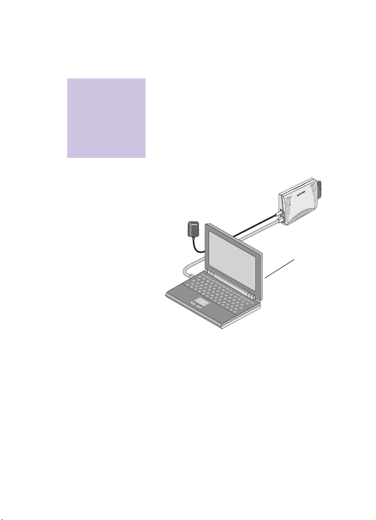
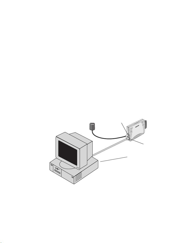
Note that you can only perform the
configuration if you are able to connect the
A040 to a PC supporting TCP/IP. In a non-TCP/
IP environment, you’ll need to set up TCP/IP
temporarily on a workstation.
power connector
Ethernet connector
host computer
Preparing to configure an adapter
13
Page 14

Installing the A040 utilities
Note: The utilities only
need to be installed on
the machine you want
to use for configuring
attached adapters.
(probably an
administrator's
machine, used for
initial setup).
Before you start to configure the A040, you’ll
need to install some system utilities and default
configuration files onto a desktop or laptop PC
(the local host, which will be directly connected
to the adapter):
• Nokia IT Proxy Manager – Utility for
configuring the adapter from a local host
• Nokia TFTP client – One way to upload new
configuration settings; the only way to
upgrade the system firmware
These are provided on the Utilities CD-ROM.
To install the Nokia IT Proxy Manager, along
with other A040 utilities:
1
Insert the
Nokia A040 Utilities CD-ROM
into the host computer’s CD drive.
The Nokia Utilities application should run
automatically – you’ll see the following
screen after a few seconds:
14
A040 Advanced User Guide
Page 15
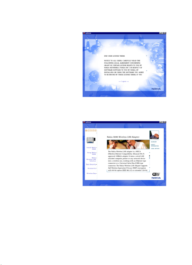
2
Double-click on the copyright text to
display the Nokia License Agreement:
3
Read the License Agreement and click
>>
I agree <<
at the bottom of the page to
display the CD-ROM home page:
4
Preparing to configure an adapter
Install Nokia A040
Click
.
15
Page 16
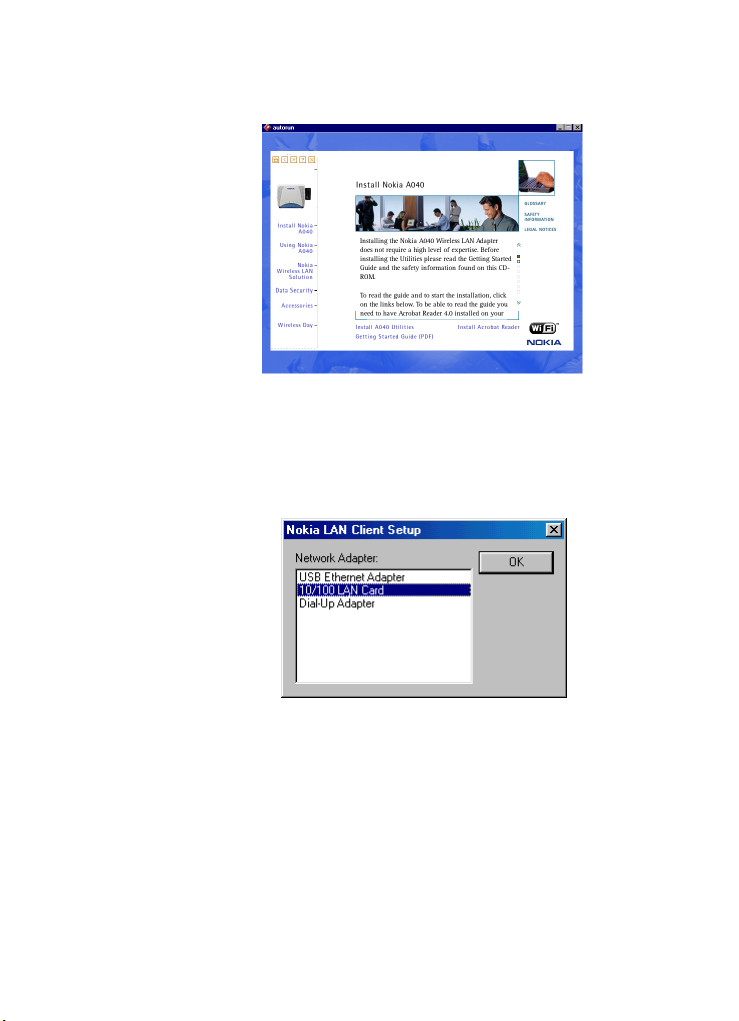
You’ll see the installation options at the
bottom of the page:
16
5
6
Install A040 Utilities.
Click
Follow the on-screen instructions to install
the utilities onto the host computer.
7
Select the network interface card used by
the local host and click
:
OK
A040 Advanced User Guide
Page 17

8
When you see the following prompt,
the Utilities CD from the drive
to reboot the local host:
then click
eject
Yes
Preparing to configure an adapter
17
Page 18
Using set-up mode
Starting the adapter in set-up mode
To put the A040 into set-up mode:
1
Switch the local host on.
2
Plug the Ethernet cable into the Ethernet
connector on the A040 and the Ethernet
port on the local host.
3
Plug one end of the A040’s power adapter
into a wall outlet.
4
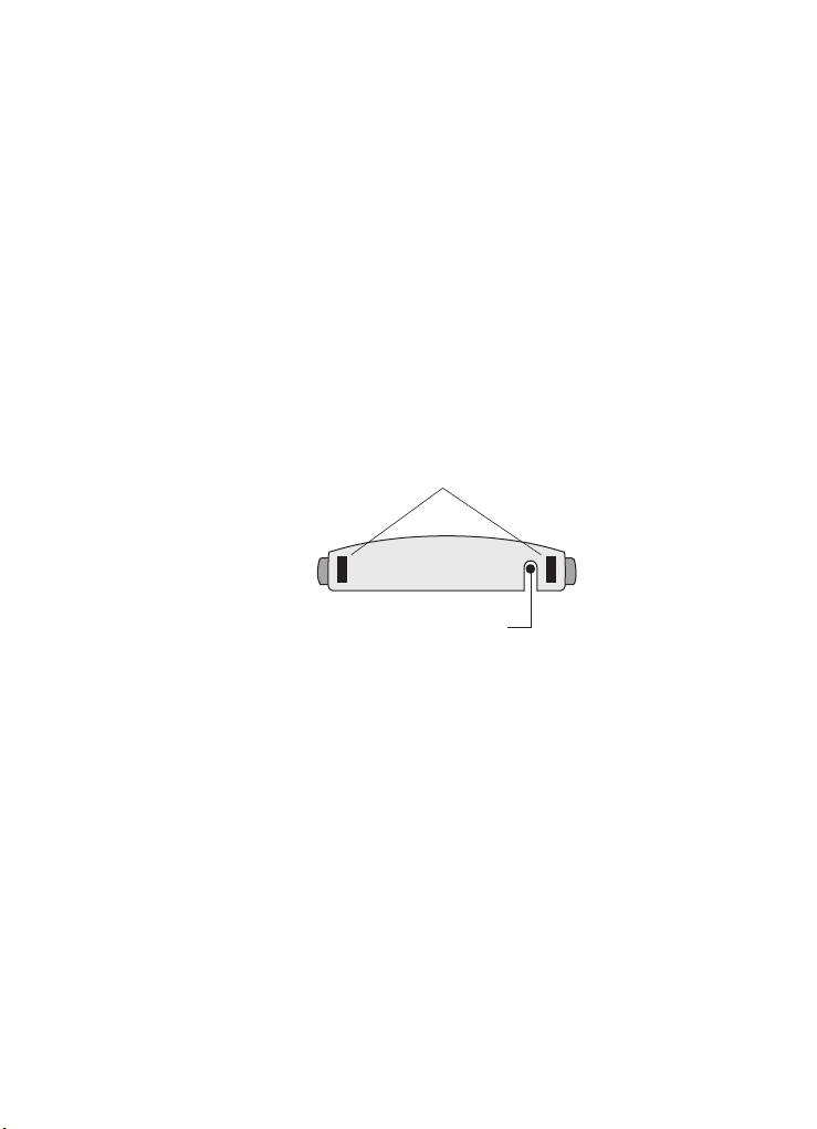
Using the tip of a ballpoint pen, press and
hold in the hidden reset button on the
underside of the unit:
5
While holding in the reset button, plug the
other end of the power adapter cable into
the unit’s power connector.
The LEDs will come on, then go out again.
6
As soon as the LEDs go out, release the reset
button.
While the unit is in set-up mode the following
special conditions occur:
• The unit beeps intermittently
• The unit does
any Access Point
• The unit will respond to
long as it is valid on the local host's subnet).
rubber
feet
reset
button
not
attempt to connect with
any
IP address (as
18
A040 Advanced User Guide
Page 19
Accessing management interfaces
Web interface
To access the Web interface while the adapter is
in set-up mode:
1
Start a Web browser on the local host.
2 Enter the following URL:
http://xxx.xxx.xxx.xxx/
where xxx.xxx.xxx.xxx is any IP address
on the same subnet as the host computer.
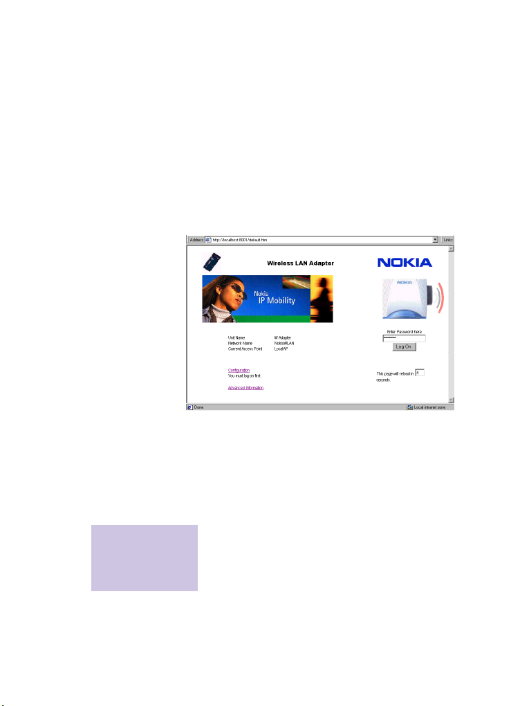
You’ll see the configuration home page:
3 Enter the password (
You can now use the Web management
interface to configure the adapter. See page 34
for a description of all the parameters.
Restarting the adapter
You must click Enter
followed by Save to
make your changes
take effect.
Preparing to configure an adapter
To make your changes take effect:
1 Click
2 Click
default) and click
Log On.
Enter to save the settings you’ve made.
Save to commit the changes. This
restarts the A040.
19
Page 20
Telnet interface
To access the Telnet interface while the adapter
is in set-up mode:
1 Choose
2 Type
3 From the Telnet window menu, choose
4 In the
5 Click
Run from the Start menu on the
local host.
Telnet and click OK.
Connect > Remote system.
Host Name field, enter any IP address
in the same subnet as that of the host
computer (you don’t need to enter a
Connect.
Port).
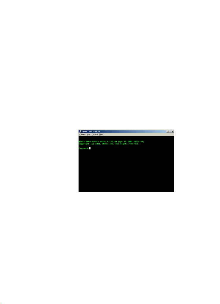
At this point, the Nokia banner should
appear in the Telnet console, followed by a
logon prompt:
20
6 Enter your password at the prompt (the
factory default password is
You’ll see the
CMD: prompt in the Telnet
default).
window.
A full list of options is given in Telnet
management interface on page 44.
A040 Advanced User Guide
Page 21
TFTP interface
You can use the TFTP interface to configure the
A040 with new settings, or to perform a system
software upgrade.
To access the TFTP interface while the adapter
is in set-up mode:
1 On the local host, click on Start > Programs
> Nokia A040 utilities > Nokia TFTP client
2 Enter any valid, unused IP address. The
address must be valid for your local subnet.
You’ll see the following window:
See page 53 for details on performing
configuration changes; see page 69 for upgrade
instructions.
.
Preparing to configure an adapter
21
Page 22

Using the Nokia IT Proxy Manager
What you’ll need
To configure the adapter using the Nokia IT
Proxy Manager, you’ll need a desktop or laptop
computer (the local host) with the following:
• Windows 95/98, Windows 2000 or
Windows NT4
• Web browser (e.g. Internet Explorer) or a
Telnet client
• TCP/IP and a configured IP address/subnet
mask (or auto-configuration)
• an Ethernet card
• Ethernet adapter cable with an RJ45 plug
(supplied) if you’re using a laptop with a
PCMCIA Ethernet card
• The A040 utilities installed (see page 14).
Connecting the adapter
With the local host on:
1 Plug the Ethernet cable into the Ethernet
connector on the A040 and the Ethernet
port on the local host.
2 Connect the A040’s power adapter to a wall
outlet and the A040 and switch on.
All the LEDs will come on, then go out.
When the unit has started up, the
will light up and the unit will emit a ‘chirp’
(three rising tones).
power LED
22
A040 Advanced User Guide
Page 23

Starting the Nokia IT Proxy Manager
Note: IT Proxy
software is only
installed on computers
used for configuring
the adapters.
To start the Nokia IT Proxy Manager:
1 From the
Nokia A040 Utilities > Run Nokia IT Proxy
Start menu choose Programs >
.
You’ll see the Nokia IT Proxy Manager icon
on the icon bar.
• To start with it will show the following icon
while it tries to find the adapter:
• When it finds the adapter, you’ll see the
following icon:
• If there is no adapter connected, you’ll see
the following icon:
Preparing to configure an adapter
23
Page 24
Accessing management interfaces using the Nokia IT Proxy Manager
Web interface
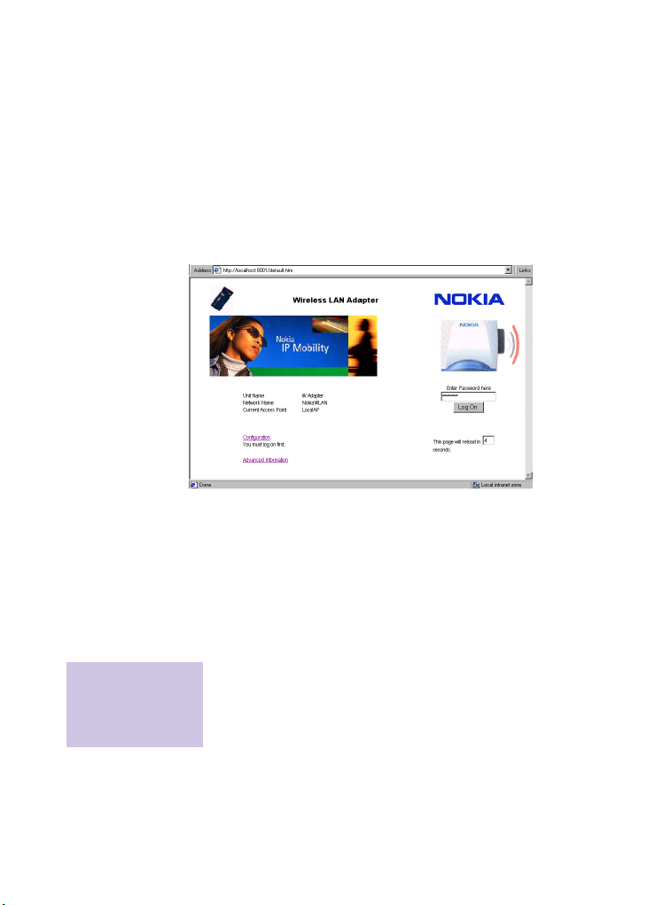
To access the Web management interface:
1 Start a Web browser on the local host.
2 Enter the following URL:
http://localhost:8001/
You’ll see the configuration home page:
Note: You must click
Enter followed by
Save to make your
changes take effect.
24
3 Enter the password (
Log On.
4 Click the
You can now use the Web management
interface to configure the adapter. See page 34
for a description of all the parameters.
Restarting the adapter
To make your changes take effect:
1 Click
2 Click
restarts the A040.
Configuration link.
Enter to save the settings you’ve made.
Save to commit the changes. This
default) and click
A040 Advanced User Guide
Page 25

Telnet interface
Telnet provides a command line interface. To
configure the A040 Telnet from the local host
via the Nokia IT Proxy Manager:
1 Choose
2 Type
3 From the Telnet window menu, choose
4 Enter
5 Enter your
You’ll see the following prompt in the Telnet
window:
You’re now ready to enter commands.
Run from the Start menu.
Telnet and click OK.
If this fails for any reason, use the Find Files
utility to search for
find a program called
Telnet. This should
Telnet.exe, on
which you should double-click.
Connect > Remote system.
localhost as the Host Name, and
8000 as the Port and click Connect
At this point, the Nokia banner should
appear, followed by a logon prompt.
Password when prompted. The
factory-set password is
CMD:
default.
Preparing to configure an adapter
25
Page 26

Making changes
You use the
configuration changes using Telnet. Commands
take the form:
set parameter value
The full list of options is given on page 44.
Restarting the adapter
To make your changes take effect:
1 Type
prompt.
This restarts the adapter with the new settings.
set command to make
restart at the command line
Nokia IT Proxy Manager Taskbar options
If you right-click on the Nokia IT Proxy
Manager’s icon on the taskbar, you’ll see the
following menu options:
•
About – Displays the current version of the
Nokia IT Proxy Manager.
26
Status – Displays the connection status of
•
the Nokia A040 and which Access Point it is
connected to (MAC address and unit name).
A040 Advanced User Guide
Page 27

• Rescan – Forces the Nokia A040 to rescan
for an Access Point. Normally this will
happen automatically. It also happens when
you start the Nokia IT Proxy Manager.
This appears when the unit conducts a
Rescan – if a unit is found it will show the
unit's MAC Address and Unit Name (see
Status above). If no unit is detected it will
show “No units found”:
• Settings – Allows you to change the ports
for Telnet and Web access (in some cases
the default ports may clash with other
services used by the computer).
Preparing to configure an adapter
27
Page 28

Using IP intercept
To use the IP intercept method:
• Your chosen management interface on the
• You can only use this method from a
• The host device (computer, printer, or
• The adapter itself must not have a fixed IP
Enabling intercepts
Before you can use IP intercepts from a remote
computer, you need to enable your chosen
interface on the adapter to accept IP intercepts.
You’ll have to do this from a local host.
An example – enabling Web intercepts
For example, if you want to be able to
configure the adapter remotely using the Web
interface:
1 Use set-up mode (see page 18) or the Nokia
2 Use set-up mode or the Nokia IT Proxy
You can use the Web or Telnet interfaces to do
this (see page 38 and page 46).
adapter (Web, Telnet or TFTP) must be
configured to accept IP intercepts
remote computer (that is, you can not use it
from a local host physically connected to
the adapter)
scanner, for example) to which the adapter
is connected must already have an IP
address
address.
IT Proxy Manager (see page 22) to remove
the adapter’s fixed IP address, if it has one.
Manager to enable Web intercepts.
28
A040 Advanced User Guide
Page 29

Accessing management interfaces using IP intercept
Web interface
To use the Web manager from a computer on
the Access Point side of the network:
1 Start a Web browser.
2 Enter a URL of the following form:
http://xxx.xxx.xxx.xxx/
where xxx.xxx.xxx.xxx is the IP
address of the host device.
You’ll see the configuration home page:
3 Enter the password (
4 Click the
You can now use the Web management
interface to configure the adapter. See page 34
for a description.
Restarting the adapter
You must click Enter
followed by Save to
make your changes
take effect.
Preparing to configure an adapter
To make your changes take effect:
1 Click
2 Click
default) and click
Log On.
Configuration link.
Enter to save the settings you’ve made.
Save to commit the changes. This
restarts the A040.
29
Page 30

Telnet interface
To use the Telnet manager from a computer on
the Access Point side of the network:
1 Choose
2 Type
3 From the Telnet window menu, choose
4 In the
5 Click
6 At the
You’ll see the following prompt in the Telnet
window:
You’re now ready to enter commands.
Making changes
You use the
configuration changes using Telnet. Commands
take the form:
The full list of options is given in Telnet
management interface on page 44.
Run from the Start menu.
Telnet and click OK.
Connect > Remote system.
Host Name field, enter the IP address
of the host device (you don’t need to enter
a
Port).
Connect.
At this point, the Nokia banner should
appear, followed by a logon prompt.
Password: prompt, enter your
password. The factory default password is
default.
CMD:
set command to make
set parameter value
30
Restarting the adapter
To make your changes take effect:
1 Type
restart at the command line
prompt.
This restarts the adapter with the new settings.
A040 Advanced User Guide
Page 31

TFTP interface
Before you use the TFTP management interface
from a remote computer, it must have a TFTP
client installed. If necessary, you can install the
Nokia TFTP client on the remote computer (see
page 14).
To access the TFTP interface from a remote
computer using the Nokia TFTP client program:
1 Click on
utilities > Nokia TFTP client
You’ll see the following window:
Start > Programs > Nokia A040
.
2 If you want, place a check in the
3 Enter the IP address of the host device (the
You can now transfer files between the remote
computer and the adapter. Please see TFTP
configuration on page 53 for details on making
configuration changes via TFTP.
Preparing to configure an adapter
Remember
recently used file names and IP addresses
box.
This will save time next time you use TFTP.
adapter should not have an IP address!) into
the
IP Address of Target field.
31
Page 32

Using a direct IP address
If the A040 has its own fixed IP address, you
can access all the management interfaces from
a local host or remote computer.
You can use exactly the same methods
described in Using IP intercept on page 28 for
accessing the various management interfaces.
The only difference is that you enter the IP
address of the adapter itself, rather than the IP
address of any host device attached to it.
32
A040 Advanced User Guide
Page 33

3. Configuration parameters
This chapter explains all the A040
configuration options.
There are many ways of accessing the
management interfaces described in this
chapter – please see Preparing to configure an
adapter on page 13.
The table below describes the different
management interfaces:
Interface Description See…
The adapter acts as a Web server and gen-
Web
Telnet
TFTP
SNMP
erates screens by which you can monitor
or configure the adapter.
You can use a Telnet program to configure
and monitor the adapter via a command
line interface.
You can use the supplied TFTP utility to
download or upload information, or configure the adapter.
You can use any suitable SNMP manager
to monitor the adapter (an SNMP management application is not supplied).
page 34
page 44
page 53
page 59
Configuration parameters
33
Page 34

Web configuration
Logging on
1 If necessary, enter the password (the default
2 Click
Once you’ve accessed the Web interface,
you’ll see the configuration home page:
password is
you.
The page will update to show
Security buttons:
default). This is filled in for
Log On.
Log Off and
34
A040 Advanced User Guide
Page 35

Viewing configuration pages
There are three pages of configuration options:
1 Click
2 Click More Options to see all the basic
Configuration on the home page to see
the basic settings:
options, plus operating mode and default
channel:
Configuration parameters
3 Click
You can click the
back to the home page.
More Options again to see the basic
and intermediate options, plus management
settings:
Home link at any time to get
35
Page 36

Making configuration changes
In general, to change a configuration option:
1 View the appropriate configuration page, as
described above.
You must click Enter
and Save to make
your changes take
effect.
2 Click
3 Click
Enter to send new settings to the Nokia
A040.
Save to restart the adapter with the
new settings.
Configuration settings
The following table explains what all the
configuration settings mean, and gives advice
on changing them:
Field Meaning
Network Name String specifying the network name for the wireless LAN.
The entry can be up to 32 alphanumeric characters, and
may include spaces.
If you’re only using one network, check the Auto Join
box (see below).
Regulatory Domain This defines the radio channels you are allowed to use,
depending on which country is set.
Select your country from the Regulatory Domain dropdown:
36
See Regulatory domains on page 67 for more
information.
Important: Use only the region setting appropriate for
the area where the adapter is used at the present time.
Using the adapter in any other region or with an
incorrect region setting may be illegal.
A040 Advanced User Guide
Page 37

Field Meaning
Unit Name String up to 16 characters used to give the adapter an
identifier name. Useful if you have multiple adapters on
a network. Accessible through proprietary SNMP MIB.
Auto Join Specifies whether the adapter will try to join any
available network (suitable for small installations).
Use fixed MAC address When selected, causes the MAC address of the radio card
in the adapter to appear on Access Point web screens of
associated stations, rather than the MAC address of the
client's PCMCIA card. The default is off.
Sound Level Sets the sound level of the unit’s built-in speaker.
Choose from Off, Medium or High.
Mode The operating mode of the adapter:
• Infrastructure – if using an Access Point
• Peer-to-Peer – if not using an Access Point
Default Channel Specifies the channel at which to start scanning for
Access Points. If you have many adapters and Access
Points, vary the default channel – that will prevent all
adapters from choosing the same Access Point.
IP address The IP address assigned to the adapter for management
purposes. Normally the network system administrator
will select this value.
If you do not want to assign an IP address, leave this
field blank.
You’ll need to set the adapter to use IP address intercept
on one or more of the management interfaces (see the
last entries in this table).
Subnet Mask If you have set an IP address, this must be set to the
value used on the adapter’s local IP subnetwork.
Gateway IP Address This is required if the management functions will be
accessed from outside the local subnetwork.
Configuration parameters
37
Page 38

Field Meaning
Web Manager Port
Telnet Manager Port
SNMP Community Defines the SNMP community name used in SNMP
Manager Access Use this to restrict access to the Web, Telnet and TFTP
Manager IP Address Enter the IP address of the workstation from which you
TFTP Intercept Specify intercept of TFTP frames received from Air to IP
WEB Intercept Specify intercept of WEB frames received from Air to IP
Telnet Intercept Specify intercept of Telnet frames received from Air to IP
SNMP Intercept Specify intercept of SNMP frames received from Air to IP
For security reasons or for remote access you may want
to make the adapter respond to non-standard port
numbers for Telnet and Web access.
Disable Telnet and/or Web manager functions by
specifying port
Telnet and Web ports are 23 and 80 respectively.
Most browsers allow access to a non-standard port
numbers using a URL of the form
http://static_IP_address:port_number
accesses (maximum 16 characters).
management interfaces. The options are as follows:
• Any - Allows any LAN or WLAN station to use the
management functions.
• Specific – Restricts access to the management functions to the machine with IP address defined in the
Manager IP Address field (see below).
want to be able to configure the adapter.
address of the host computer.
Note that Intercepts are only active if the A040 does not
have a fixed IP address.
If the A040 has its own IP address, setting the intercept
on or off has no effect – use the direct IP address
method (see page 32).
address of the host computer. Intercepts are only active
if the A040 does not have a fixed IP address.
address of the host computer. Intercepts are only active
if the A040 does not have a fixed IP address.
address of the host computer. Intercepts are only active
if the A040 does not have a fixed IP address.
0 or Off. The default values for the
38
A040 Advanced User Guide
Page 39

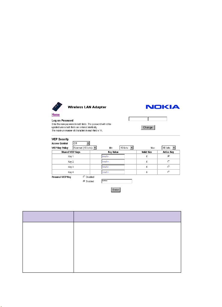
Changing your password
To change your password:
1 After logging on, click the
below the password box on the home page.
2 On the resulting page enter your new
password twice into the two fields above the
Change button. Then click
The password can be any alphanumeric string
up to 16 characters long.
Security button
Change:
Configuration parameters
39
Page 40
Changing WEP security measures
Your A040 is capable of using WEP security
measures to prevent unwanted access to your
network.
To change WEP security measures:
1 After logging on, click the
below the password box on the home page.
2 On the resulting page, amend the
Security
options as necessary and click
Enter:
The following table explains what all the
options mean:
Security button
WEP
Item Description
Access Control Specifies whether WEP is active, and the admission
policy.
Off WEP mode deactivated
On WEP wireless clients allowed to connect,
using shared or personal WEP keys
WiFi WEP Special mode used with some non-Nokia WiFi
compatible systems; not generally
recommended
40
A040 Advanced User Guide
Page 41

Item Description
WEP Key Policy This parameter determines the number of bits allowed
for the WEP keys.
• Normal – IEEE802.11 compatible mode: 40 bits
• Strong – 128-bit key length
• Custom – Use Min and Max key length settings:
40 (enter keys as ten octets)
56 (enter keys as 14 octets)
64 (enter keys as 16 octets)
96 (enter keys as 24 octets)
104 (enter keys as 26 octets)
128 (enter keys as 32 octets)
For example, setting Min to 40 and Max to 96 will allow
keys of 40, 56, 64 or 96 bits.
Key Value These fields are used to enter the shared WEP key values.
Note that the values are not displayed after entry (they
appear as ****). If you want to enter keys in hexadecimal,
prefix them with
Important: The keys will only work if their length is
within the Valid Size limits (see below). A valid key is
shown in green. If you enter a key that is of incorrect
value, it will be shown in red.
Valid Size (Read only) Tells you the valid size of the password for
the current setting of WEP Key Policy. For an ASCII key
entry this indicates how many ASCII characters should
be in the WEP Key.
Active Key This determines which of the four shared WEP keys is
active (i.e. used for transmission).
Personal WEP key Allows you to set (or disable) a personal WEP key for the
A040. The disable and enable buttons allow you to
activate or disable the Personal WEP Key.
0x.
Configuration parameters
41
Page 42
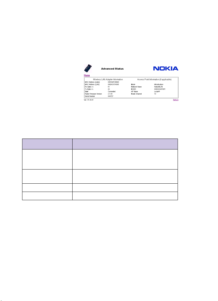
Viewing status information
To view the current state of the adapter:
1 Click the
home page.
You’ll see the following status page:
Advanced Information link on the
2 Click
Refresh at any time to update the
status display.
Status values
The following table explains the status values:
Item Description
MAC Address (radio) The MAC address used by the adapter for IEEE802.11
transmissions; this is learned from the attached host
computer.
MAC Address (LAN) The MAC address of the A040 used for management
functions when accessed from the LAN side
Rx Bytes/s Average bytes/sec in 10 second window
Tx Bytes/s Average bytes/sec in 10 second window
42
A040 Advanced User Guide
Page 43

Item Description
State Connection status:
• Dormant – Unit is not communicating with a network. (Usually implies the radio card is not working)
• Scanning – Unit is looking for an Access point
• Joining – Unit has found an Access Point and is
attempting to join the network
• Authenticate – Unit has found an Access Point and is
attempting to Authenticate
• Associate – Unit has found an Access Point, authenticated and is now attempting to associate
• Connected – Unit has successfully joined a network
See also Special LED/sound sequences in the Getting
Started guide
Radio Firmware Version The current version of the radio firmware.
Serial Number The serial number of the device.
Mode Operating mode:
Network Name Target network name (that which the adapter will try to
BSSID BSSID (usually the MAC address) of the Access Point
AP Name Name of the Access Point to which the A040 has
Radio Channel Current radio channel in operation
• Infrastructure – if using one or more Access Points
• Peer-to-Peer – if not using an Access Point
join when scanning) or connected network name. Note
that in the case of Auto Join this will show the network
name of the Access Point which has been joined
which has been joined
connected
Configuration parameters
43
Page 44

Telnet management interface
Telnet provides a command line interface to
configure A040 adapters. Telnet interface on
page 20 tells you how to access the Telnet
interface.
When you see the
window you’re ready to enter commands.
Making changes and restarting
You use the set command to make
configuration changes using Telnet.
Configuration commands take the form:
set parameter value
To make the changes take effect:
1 Type
This restarts the adapter with the new settings.
restart at the prompt.
CMD: prompt in the Telnet
44
A040 Advanced User Guide
Page 45
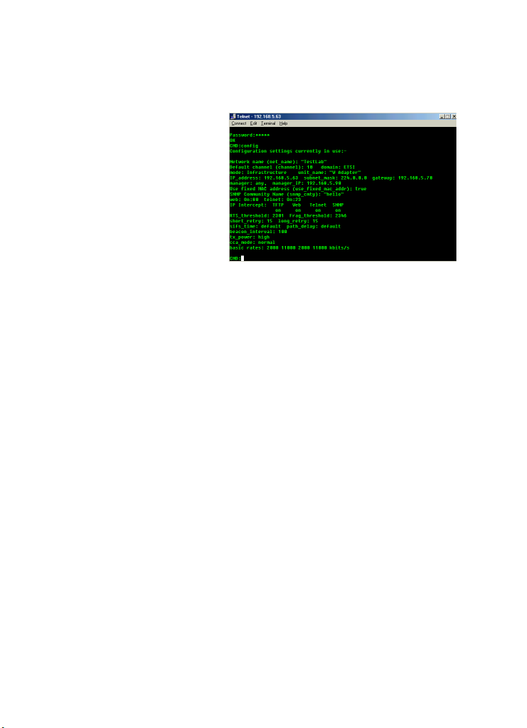
Viewing changes
Use the config command to view current
settings:
Use the CONFIG+ command to view the new
settings for parameters which will take effect
after performing a restart.
Configuration parameters
45
Page 46

Configuration settings
The following parameters can be set using the
Telnet command line program:
Item Comment
auto_join Set on if the adapter is to auto-join with any available
Access Point. Note that the Telnet config command
reports this as --- Automatic ---
off
– adapter will only join the network specified by
net_name. Default is on.
basic_rate Controls the radio bit rate when running in peer-peer
mode. Valid values are:
1000, 2000, 5500, 11000 (written in kbits/s).
The command can take a list of parameters, for example:
set basic_rate 11000 5500
beacon_interval Time taken between two beacons.
beep_level Controls the volume of the built-in beeper. Valid settings
are:
off completely suppressed
quiet or medium the normal (default) sound
level
loud or high maximum volume
cca_mode Channel Clear Assessment – controls detection of
activity over the air interface.
channel Default channel at which to start scanning (dependent
on Domain setting).
domain The regulatory domain (see Appendix A – Regulatory
domains for definitions.
dtim_interval Interval setting for Delivery Traffic Indication Message.
frag_threshold An IEEE802.11 parameter which determines the
maximum size of frames sent by the radio. Frames larger
than frag_threshold are sent in several pieces.
Lowering the value of frag_threshold can improve
throughput for poor radio conditions, but reduces
throughput for good radio conditions.
46
A040 Advanced User Guide
Page 47

Item Comment
gateway IP address of gateway. Required if adapter is to be
managed from remote location.
help Displays all non-settable commands., such as config.
See Command summary on page 52.
intercept Specify intercept of TFTP, Web, SNMP and Telnet frames
received from Air to IP address of the host computer.
Note that Intercepts are only active if the adapter does
not have a fixed IP address. For example:
set intercept web on
ip_address Fixed IP address of adapter.
If you don’t want to set an IP address, just type
set ip_address
with no parameter (this actually sets the IP address to
0.0.0.0).
long_retry Specify value of “long retry” to radio.
manager Used to control access to web, Telnet and TFTP
management functions. Possible values are:
any allows any station to use management
functions
specific allows access by specific stations only
(see manager_ip below).
manager_ip Specifies up to four stations allowed to use management
functions (if set manager specific applies). The
format of the command is:
set manager_ip ip_address
where:
ip_address IP address of the manager’s station
For example:
set manager_ip 192.168.0.1
mode Infrastructure or Peer-Peer.
net_name Network name (default is Nokia WLAN). See also
auto_join parameter above.
password Configuration password can be changed if current
password is known.
rts_threshold Specify value of “rts threshold” to radio.
Configuration parameters
47
Page 48

Item Comment
set help Displays the list of all settable parameters. The
parameters are listed in the Item column and described
in the Comment column.
short_retry Specify value of “short retry” to radio.
sifs_time IEEE802.11 parameter – Short InterFrame Space Time
setting.
snmp_cmty Community name of adapter.
specific_key Allows you to specify a personal WEP key. You can turn
personal WEP key off, or specify a hexadecimal or ascii
string. For example:
set specific_key off
set specific_key hex ae325e092c
set specific_key ascii mywepkey
stats air Reports on data transferred over the wireless LAN. Stats
are reported for both the last 10 second period, and
accumulated since the unit was last restarted or the
stats were cleared.
stats clear Wipes out the cumulative stats for both LAN and air.
stats LAN Reports on data transferred via the Ethernet port. Stats
subnet_mask This is required if an IP Address is assigned. It denotes
telnet TCP Port number of Telnet server.
tx_power Power setting for transmission.
unit_name User friendly name for adapter. Accessible through
use_fixed_mac_addr Controls whether the unit uses the radio card’s MAC
are reported for both the last 10 second period, and
accumulated since the unit was last restarted or the
stats were cleared.
whether the client is local or remote.
1=default
2,3,4 are high power values
proprietary MIB.
address on the radio interface or reflects the client’s
MAC address. Valid values are
true and false.
48
A040 Advanced User Guide
Page 49

Item Comment
web TCP Port number of web server.
wep_key Assigns a key value to one of the four slots. The
command takes the form:
set wep_key key_number key_value
where key_number selects which shared WEP key (1,
2, 3 or 4) is being entered, and key_value assigns it a
value. key_value must follow the WEP key policy set
by the Access Point.
Examples:
set wep_key 2 ae325e092c
assigns the value ae325e092c to shared WEP key
number 2.
set wep_key 3 n
assigns a null value, deactivating shared WEP key
number 3.
wep_key_active Specifies which of the four shared WEP keys is active. For
example:
set wep_key_active 3
means shared WEP key 3 is active.
wep_key_range Allows you to specify a custom WEP key policy. The
command takes the form:
set wep_key_range min max
where min and max can be one of the following:
40 40-bit encryption
56 56-bit encryption
64 64-bit encryption
96 96-bit encryption
104 104-bit encryption
128 128-bit encryption
For example:
set wep_key_range 56 96
means the adapter will accept keys of a minimum length
of 56 bits, up to a maximum length of 96 bits.
Configuration parameters
49
Page 50

Item Comment
wep_mode Specifies whether WEP (wire equivalent privacy) is
active, and the admission policy. Please see the
documentation that came with your Access Point for a
full description of WEP.
open WEP mode deactivated
wep WEP wireless clients allowed to connect,
using shared or personal WEP keys
wifi Special mode used with some non-Nokia WiFi
compatible systems. Station may use open
authentication to associate with the Access
Point then switch to shared WEP key.
Personal WEP keys not supported. Mode
provided for compatibility with other vendor
equipment; not generally recommended.
personalA personal WEP key encrypts the link
between a station and an AP. This key can be
different for each station. The key encrypts
unicast frames (frames directed at a
particular station or AP). There is one personal
WEP key allowed per station and the AP must
be configured to get the key from an external
Radius server, or it should be included in the
NID table. If a personal WEP key is not used,
the current shared WEP key is used instead.
50
A040 Advanced User Guide
Page 51

CLM commands
Help on commands
This section gives a complete listing of the CLM
commands available on the Nokia A040. For an
explanation of how to access the CLM, see
Telnet interface on page 25.
The basic command syntax is:
command parameter1 value
The format of value depends on the parameter
you’re changing. Some values are simple
numbers, some are strings and some are special
values such as IP addresses.
The command and parameters are separated by
spaces.
• You can correct typing errors using the
backspace key.
• You can terminate certain commands and
return to the command prompt by pressing
Ctrl-C.
• You can repeat the previous command by
pressing the space bar at the command
prompt.
• To see a summary of commands, type:
help (or ?)
• To get help on a specific command, type:
help command (or ? command)
For example:
help ping
• To see a list of parameters for the set
command, type:
set help (or set ?)
Configuration parameters
51
Page 52

Command summary
Command Description
config Displays current system configuration settings.
config+ This works like the config command but shows the settings that will
take effect on the next restart.
exit Performs a logout from the command line (and is functionally
identical to the logout command). For a telnet connection, it also
disconnects the telnet session.
help or ? Issued on its own, displays a summary of all commands.
Can also display on a specific command.
log dump Displays the contents of the initialization log on the screen.
log clear Clears out the log information.
logout Exits the CLM. Re-enter the password to use CLM.
restart Causes the Nokia A040 to re-initialize. This is equivalent to turning
the power off and on again. Normally this command is issued after
configuration changes. Restarting the unit can be disruptive to
currently connected users.
set See Telnet management interface on page 44.
stats lan
stats air
status Returns the following details: LAN MAC Address; Associated Access
ver Displays product name, along with version and copyright
wep Displays current WEP settings. Radius Server IP Address fields are
wep+ This works like the wep command but shows the settings that will
Displays traffic statistics for the last 10-second interval (cumulative
since last cleared or system reset). Clear stats using the command
stats clear.
Point; CurrentNetwork; Current IEEE 802.11 BSSID; Current
Channel.
information for the Nokia A040 software.
not returned if Radius lookup is not enabled (via the wep_mode
command).
take effect on the next restart.
52
A040 Advanced User Guide
Page 53

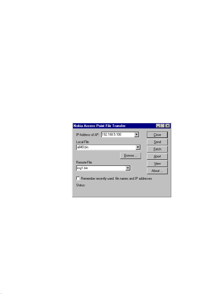
TFTP configuration
All the parameters listed in Configuration
settings on page 46 can be read and set using
the TFTP transfer file
Preparing to configure an adapter on page 13
tells you how to start the TFTP client. Once it is
running, you can transfer files between a local
or remote computer and the adapter:
config.txt.
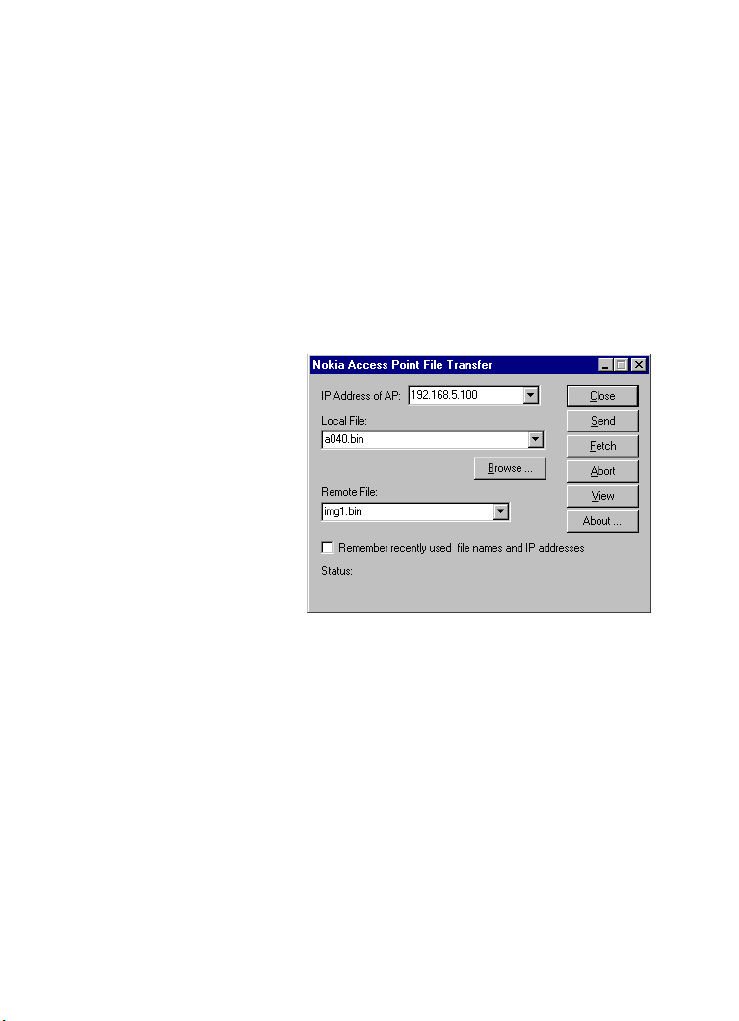
You can click Browse
to specify a file.
The drop-down menu
lists recently-used
files.
Configuration parameters
1 In the Local File field, enter the name of the
source file (when sending) or destination
file (when fetching) on your local disk or
network drive.
2 In the
Remote File field, choose the name of
the A040 ‘file’ you want to send or fetch
from the drop-down menu.
53
Page 54

You can click Abort to
interrupt a send or
fetch.
3 Click Send or Fetch.
If the operation is successful the status
message should read ‘File Sent OK’ or ‘File
Fetched OK’ as appropriate.
Please see config.txt on page 56 for details on
making configuration changes via TFTP.
Possible error messages
You may see one or more of the following error
messages during file transfer:
Message Possible causes
timed out
unknown file
upload in
progress
You typed the wrong IP address,
you have not connected to the
A040, or the A040 is configured
not to accept TFTP from your
station.
You probably made an invalid entry
in the
Remote File field.
Another station is performing an
upload at the same time, or the
previous upload was not completed
successfully. Try again after 30
seconds.
54
A040 Advanced User Guide
Page 55

TFTP file descriptions
This section gives a detailed description of each
file available for transfer between a client and
the A040 using TFTP.
log.txt
The A040 maintains a log file which is updated
when the unit is initialized.
This file keeps a record of each initialization.
The uploaded log file is stored in regular text
format.
Here’s an example of a log file:
Initializing version: V1.00.01
Initialize LAN port...
LAN Port ready, Message : Web Config Update
Initializing version: V1.00.01
Initialize LAN port...
LAN Port ready, Message : Flash Update
Initializing version: V1.00.01
Initialize LAN port...
LAN Port ready, Message : CLM Request
Initializing version: V1.00.01
Initialize LAN port...
LAN Port ready,
Configuration parameters
55
Page 56

img1.bin
img1.bin is the name of the ‘file’ on the A040
where the firmware for the adapter is stored.
From time to time during the warrantee period,
Nokia may make new versions of firmware
available. New releases might have additional
features or might fix anomalies that have been
reported in the operation of the unit. In such
cases Nokia will provide a binary file as
denoted by the extension
a040.bin), along with upgrade instructions.
.bin (e.g.
For example, to upgrade the A040 firmware:
1 Using the TFTP client, select
the
Local File, and img1.bin as the Remote
File
.
2 Click
Send.
a040.bin as
config.txt
This file is a text file containing all the A040’s
important configuration settings.
A system manager may want to keep a record
of the A040’s configuration settings for future
reference, or as a backup before performing
any new configuration.
You can use a backup copy of config.txt if you
run into problems while configuring or
upgrading the A040.
An example of a config.txt file is shown below:
56
A040 Advanced User Guide
Page 57

Modifying the config.txt file
Note that some entries are commented out
(lines starting with ‘
/*’). This denotes entries
that are set to a default value. You can delete
these lines without affecting the result when
the file is downloaded to the A040.
If you want to modify a parameter, delete the
comment characters and amend the parameter
accordingly.
For example, to change the radio channel:
1 Use a text editor to open
config.txt.
2 Modify the file as follows:
Old line:
/*%channel: 10
Modified line: %channel: 11
3 Save config.txt.
4 Send the file to the A040.
Configuration parameters
57
Page 58

When you send config.txt, the following
action is taken by the A040:
1 The new configuration file is read in and
checked for format. If there are any format
errors the configuration is not updated
2 If the send is good, all the parameters
(except password) are reset to their default
value.
3 New settings from the config.txt file are
loaded into the A040.
4 The A040 performs a restart with the new
settings.
Monitoring information
TFTP can download the contents of the log.txt
file which may contain diagnostics information
in the event of software failures.
58
A040 Advanced User Guide
Page 59

SNMP management interface
The A040 has a built-in SNMP Agent capability
which allows integration into SNMP managed
enterprise environments. The Agent supports
SNMP V1.0 requests and provides data from
the following MIBs (supplied as files when you
install from the Utilities CD-ROM):
Data Supplied in file
RFC1213 (MIBII)
IEEE802.11 MIB
ETHERLIKE MIB (partial)
Proprietary MIB
RFC1213.mib
IANAifType.mib
IEEE80211.mib
ETHERLIKE.mib
Nokia-A040-MIBv1.mib
The source text for these MIBs is provided on
the Utilities CD-ROM supplied with your Access
Point. The MIBs are provided in ASCII text
format for easy incorporation into SNMP
Manager Products.
Items which are listed as Read/Write in the MIB
will cause an error response if a Set command
is issued.
You cannot configure an adapter using SNMP.
Configuration parameters
59
Page 60

MIB Summary – RFC1213 – MIB II (1.3.6.1.2…)
The Version of RFC1213 supplied has been
modified to recognize the IEEE802.11 interface
type The following is a summary of the sections
of MIBII indicating which parts of the MIB are
supported:
System All fields supported (Read only).
The Contact, Name and Location values can be set using
the Web manager function.
Interfaces All fields supported. There are two entries in the Inter-
face table. Interface 1 is the Ethernet Interface and
Interface 2 is the IEEE802.11 Interface.
AT Not Supported.
Internet Protocol All fields supported (Static information).
ICMP Supported as appropriate.
TCP TCP connections are shown in an eight-row table. All
fields are supported in each table row. However, the table
size is fixed.
UDP Supported for UDP listeners TFTP and SNMP.
EGP Not supported.
Transmission DOT3 Stats Table supported (partial).
SNMP All fields supported.
60
A040 Advanced User Guide
Page 61

IEEE802.11 MIB (1.2.840.10036…)
The IEEE802.11 Standard MIB is defined as an
SNMP V2.0 MIB. The MIB supplied on the
Nokia A040 Utilities CD-ROM has been
converted to an SNMP V1.0 format for easy
integration into a wide range of managers.
Many of the entries in the MIB are not relevant
to the A040 because they refer to some
capability (such as frequency hopping) which is
not supported. The following groups are
supported:
Dot11SMT Station Configuration Table All entries supported (Read only)
Dot11SMT Authentication Algorithms Table All entries are static
Dot11SMT WEP Default Keys Not supported
Dot11SMT WEP Key Mapping Table Not supported
Dot11SMT Privacy Table Supported
Dot11SMT SMT notification Not supported
Dot11MAC Operation Table Fully supported (Read only)
Dot11MAC Counters Table Fully Supported
Dot11MAC Group Addresses Table Not Supported
Dot11RES Static entry
Dot11PHY Fully supported for Direct
Sequence
Configuration parameters
61
Page 62

Nokia proprietary MIB
The following information is provided as part
of the Nokia MIB.
System information
The entries in this section describe
characteristics of the adapter:
Serial number Serial number of unit hardware.
Should correspond to exterior label.
Hardware Information Special information about this unit (normally shows
Unknown).
Software Version Shows Version number of firmware and BIOS in flash
memory.
Software Build Date Compile date of firmware (may be useful for support).
62
A040 Advanced User Guide
Page 63

System configuration
The entries in this group relate to the current
configuration of the adapter:
Name User-assigned name of adapter.
Auto Join Indicates whether the unit will scan or look for a specific
network.
Management Address The IP Address of the specific manager.
Operating Mode Infrastructure or peer-to-peer
Net Name Network Name in ASCII text format.
Telnet Access Indicates whether Telnet access is enabled.
Telnet Port TCP/IP port number on which Telnet service is provided.
Web Access Indicates whether Web access is enabled.
Web Port TCP/IP port number on which Web service is provided.
Management Enable Global setting of Management enable flag (all, none,
specific).
Gateway Address IP address of network gateway configured into adapter.
Configuration parameters
63
Page 64

Radio table
Note that the counters in this group are
measured from the adapter’s perspective,
treating the PCMCIA radio card as an
independent device. Since the PCMCIA radio
card contains its own MAC processor there may
be small differences between the numbers
reported in this group and those reported by the
IEEE802.11 MIB which are measured inside the
PCMCIA radio card. Note that counters are 32bit and overflow back to 0.
Radio Interface Index Fixed value of 2.
Radio Status indicates up, down or not present. The latter is the
case if the PCMCIA slot is empty.
Radio Type Identifies the type of PCMCIA radio card installed.
Radio Description Taken from the CIS of the PCMCIA Radio card.
Radio Firmware Indicates the version of firmware used by the PCMCIA
radio MAC processor.
Radio Usage The percentage utilization over a recent 10 second inter-
val (0 – 100%).
Radio Rx All Frames Counter of frames received from PCMCIA card.
Radio Rx Mgmt Frames Counter of management frames received from PCMCIA
card.
Radio Rx Data Frames Counter of data frames received from PCMCIA card.
Radio Rx Copied Octets Counter of total bytes copied from PCMCIA radio card.
Radio Rx Frame Discards
Radio Tx All Frames All frames sent to the PCMCIA radio card.
Radio Tx Sent Octets Counter of total bytes copied to PCMCIA radio card.
Radio Tx Fails Count of frames for which re-transmission was required.
Frames discarded by adapter due to unspecified problem.
64
A040 Advanced User Guide
Page 65

LAN table (Ethernet)
Note that counters are 32 bit and overflow back
to zero.
LAN Interface Index Fixed value of 1.
LAN Status Indicates up or down (if disabled by management
process).
LAN Current Interface Indicates 10baseT.
LAN Rx All Frames Counter of all frames received by LAN interface.
LAN Rx Accept frames Counter of frames which are copied into adapter for
processing.
LAN Rx Copied Octets Counter of bytes transferred into adapter from LAN
interface.
LAN Rx Frame Discards Frames discarded by adapter due to unspecified problem.
LAN Tx All Frame Counter of all frames sent to LAN interface.
LAN Rx Sent Octets Counter of Bytes transferred to LAN interface.
Distribution
Information on the mandatory A040 Access
Point internal distribution bridge table.
Current Network ESSID – Client Adapter.
Current Access Point The name of the current Access Point connected.
Configuration parameters
65
Page 66

66
A040 Advanced User Guide
Page 67

Appendix A – Regulatory
domains
This appendix lists the regulatory domains
appropriate to various countries. Use only the
region setting appropriate for the area where
the adapter is used at the present time. Using
the adapter in any other region or with an
incorrect region setting may be illegal.
The regulatory domain is set at the factory, and
should be correct for the region in which you
purchased the unit. If you need to change it,
refer to the table below:
Country Regulatory domain
USA USA
Austria
Denmark
Finland
Germany
Iceland
Ireland
Italy
Norway
Spain
Sweden
Switzerland
UK
Japan Japan
Canada Canada
Europe
a
a. If using the CLM to set the regu-
latory domain, you should enter
set domain ETSI
67
Page 68

68
A040 Advanced User Guide
Page 69

Appendix B – Upgrading the
A040
You can use the TFTP interface to perform a
system software upgrade, if one is supplied by
Nokia. You should do this from the local host
(the PC on which you installed the A040
utilities – see page 14).
Starting in set-up mode
To put the A040 into set-up mode:
1 Switch the local host on.
2 Plug the Ethernet cable into the Ethernet
connector on the A040 and the Ethernet
port on the local host.
3 Plug one end of the A040’s power adapter
into a wall outlet.
4 Using the tip of a ballpoint pen, press and
hold in the hidden reset button on the
underside of the unit.
5 While holding in the reset button, plug the
other end of the power adapter cable into
the unit’s power connector.
The LEDs will come on, then go out again.
6 As soon as the LEDs come on again, release
the reset button.
69
Page 70
While the unit is in set-up mode the following
special conditions occur:
• The unit makes an intermittent beeping
sound
• The unit does not attempt to connect with
any Access Point
• The unit will respond to any IP address.
Accessing the TFTP interface
To access the TFTP interface:
1 Click on
utilities > Nokia TFTP client
You’ll see the following window:
Start > Programs > Nokia A040
.
70
2 Enter any valid, unused IP address. The
address must be valid for your local subnet.
A040 Advanced User Guide
Page 71

Uploading the software image
If Nokia supply you with a new software image
for the A040, it will be called something like
A040.bin. For example:
1 In the
2 In the Remote file box select img1.bin
3 Click the Send button.
The new image will be sent to the adapter.
When the upgrade is complete, there will be a
single, long beep and the unit will reboot. It is
important not to power off the unit during this
process. Failure to observe this may leave the
unit in an unrecoverable state, requiring
factory repair.
Local file box enter A040.bin
71
Page 72

72
A040 Advanced User Guide
Page 73

Appendix C – Resetting factory
defaults
If the configuration settings have been changed
you can revert back to the factory default
settings as follows:
Starting in set-up mode
To put the A040 into set-up mode:
1 Switch the local host on.
2 Plug the Ethernet or USB cable into the
Ethernet connector on the A040 and the
Ethernet port on the local host.
3 Plug one end of the A040’s power adapter
into a wall outlet.
4 Using the tip of a ballpoint pen, press and
hold in the hidden reset button on the
underside of the unit.
5 While holding in the reset button, plug the
other end of the power adapter cable into
the unit’s power connector.
The LEDs will come on, then go out again.
6 As soon as the LEDs go out, release the reset
button.
While the unit is in set-up mode it makes an
intermittent beeping sound.
7 Press and hold the reset button until the
power LED flickers red.
While the button is being held, the beeping
will become higher in pitch.
73
Page 74

8 Hold the reset button for the count of five
higher-pitched beeps.
9 Release the reset button.
10 After the defaults have been loaded, the
beeping should return to the lower pitch.
11 Switch the adapter off and then on again
(by removing and replacing the power
cable).
The adapter will start beeping as it searches for
and tries to connect to an Access Point.
74
A040 Advanced User Guide
Page 75

Index
A
A040.bin 71
abort
TFTP transfer 54
Access Control 40
active key 41
setting via CLM 49
adapter
connecting to host 22
address intercept 11
Advanced Information link 42
AP Name 43
Auto Join 36, 37, 63
auto_join 46
B
basic_rate 46
beacon_interval 46
beep_level 46
beeps 74
BSSID 43
C
cca_mode 46
channel 43, 46
CLM 8
CMD prompt 20, 25, 30, 44
commands 51
help 51
config command 52
Telnet 45
config+ command 52
config.txt 56
modifying 57
configuration
home page 19, 24, 29
options 33
pages 35
settings 36
techniques summary 12
Configuration link 35
conventions 3
Current Access Point 65
Current Network 65
D
default
channel 37
IP address intercept 11
password 25
direct IP address 32
domain 46
dtim_period 46
E
enabling Web intercepts 28
error messages
TFTP client 54
exit 52
75
Page 76

F
factory defaults 73
password 25
fetch 54
fixed IP address 28, 32
frag_threshold 46
G
gateway 47
IP address 37, 63
H
help
CLM commands 51
home page 19, 24, 29
host 9
connecting to adapter 22
Host Name field 30
I
img1.bin 56, 71
install
Windows 95/98/2000 14
installation 13
intercept 11, 47
IP address
configuration options 7
IP address intercept 11, 28
accessing 9
ip_address 47
K
key
active 49
Key Value 41
L
LAN Interface Index 65
LEDs
start-up operation 22
local file 53
local host 9, 14, 22
using Telnet 25
log clear command 52
log dump command 52
log.txt 55, 58
logging on 34
logout command 52
long_retry 47
M
MAC Address (LAN) 42
MAC Address (radio) 42
management
functions 8
Management Address 63
Management Enable 63
manager 47
Manager Access 38
Manager IP Address 38
manager_ip 47
MIB 59
source files 59
mode 37, 43, 47
76
A040 Advanced User Guide
Page 77

N
Name 63
Net Name 63
net_name 47
network name 36, 43, 63
Nokia IT Proxy Manager 9, 14
accessing 9
configuration requirements 22
configure
requirements 22
via Telnet 25
Nokia proprietary MIB 62
Nokia TFTP client 14, 21
O
operating mode 63
R
radio channel 36
Radio Interface Index 64
Refresh 42
regulatory domain 36
valid settings 67
Regulatory Domain drop-down
36
remote file 53
reset button 18, 69, 73
restart
via Telnet 26, 30
via Web interface 19, 24, 29
restart command 52
revert to factory defaults 73
rts_threshold 47
Rx Bytes/s 42
P
password 34, 47
changing 39
factory default 25
prompt 30
Personal WEP key 41
port
Telnet via proxy manager 25
power LED 73
proprietary MIB 62
S
Security button 40
send 54
Send button 71
set
command 26, 30
regulatory domain 36
specific managers 38
set command 52
set-up mode 9
accessing 18
accessing web interface 19
Telnet 20
TFTP 21
upgrading adapter 69, 73
77
Page 78

shared WEP key
active 49
deactivating 49
setting 41
setting active key 49
short_retry 48
sifs_time 48
SNMP 8, 11, 33, 38, 59
SNMP Intercept 38
snmp_cmty 48
software image
uploading via TFTP 71
Sound Level 37
specific managers 38
specific_key 48
State 43
stats air 48
stats clear 48
stats command 52
stats LAN 48
Subnet Mask 37
subnet_mask 48
system utilities 14
T
TCP/IP 7
Telnet 11, 33, 48
access 63
accessing in set-up mode 20
config command 45
manager 30
port 38, 63
restart command 26, 30
set command 26, 30
specific managers 38
via Nokia IT Proxy Manager 25
Telnet Intercept 38
Telnet.exe 25
TFTP 8, 11, 31, 33, 70
accessing in set-up mode 21
client 14, 21
error messages 54
files 55
log.txt 58
specific managers 38
upgrading adapter 69
Tx Bytes/s 42
tx_power 48
78
A040 Advanced User Guide
Page 79

U
Unit Name 37
unit_name 48
upgrade 69
upload 14
use fixed MAC address 37
use_fixed_mac_addr 48
V
Valid Size 41
ver command 52
W
Web 8, 11, 33
access 63
configuration
web pages 35
configuration home page 19,
24, 29
interface 24, 29
port 38
restarting after config. changes
19, 24, 29
setting TCP port number 49
specific managers 38
Web interface
accessing in set-up mode 19
Web Port 63
WEP 40
key policy 41
wep command 52
WEP Key Policy 41
wep+ command 52
wep_key 49
wep_key_active 49
wep_key_range 49
wep_mode 50
79
Page 80

80
A040 Advanced User Guide
 Loading...