

Page 1
Owner's Manual
MEDIAMASTER
9450 S
Page 2

GB 2
Page 3

MEDIAMASTER 9450 S
Contents
FOR YOUR SAFETY 4
Rear panel 4
Front panel 5
INSTALLATION OF THE MEDIAMASTER 5
Connecting the Mediamaster to the satellite
dish 6
Connecting the Mediamaster to a TV set 6
Connecting to a TV and a video recorder 7
If your VCR does not have a SCART-
Connector 7
Connecting to an analogue satellite-
receiver and a video recorder 7
Connecting to Hi Fi system 8
Preparing the remote control 8
Before you continue 8
REMOTE CONTROL 9
BASIC SETTINGS 10
Tuning procedure when RF
Connections are used 10
The Welcome Menu 11
Language settings 11
Antenna Satellite configuration 11
Automatic channel Search 12
Manual channel Search 13
VIEWING TV 13
General information 13
TV screen format 14
Start/stop watching TV 14
Select channel 14
Program Information, the i button 14
TV Guide 15
The Radio button 15
Volume level 15
List of TV channels 15
List of Radio channels 16
Video recorder 16
Subtitling and Teletext. The TEXT Button 16
SETTING FROM THE MAIN MENU 16
TV channels and radio channels 17
TV Guide and Radio Guide 17
Edit Channels 17
Rearrange List 18
Rename List 18
Add channels 18
Lock channels 18
Rearrange channels 19
Remove channels 19
USER PREFERENCES 19
Parental control 19
Language settings 20
System settings 20
On/Off Timer setting 21
GAME 21
INSTALLATION SUBMENUS 22
Antenna Satellite configuration 22
Automatic channel search 22
Manual channel search 22
Advanced channel search 22
Reinstall 23
System Information 23
GLOSSARY OF TERMS 24
PROBLEM SOLVING 25
TECHNICAL SPECIFICATION 26
MENUS SCREEN STRUCTURE 27
Nokia Multimedia Terminals operates a policy of continuous development.
Therefore we reserve the right to make changes and improvements to any
of the products described in this manual without any prior notice.
The EMC Directive 89/336/EEC is applied to this product.
DiSEqC is a trademark of EUTELSAT
Nokia is a registered trademark of Nokia Corporation.
Copyright 2000. Nokia Multimedia Terminals.
All rights reserved.
GB 3
Page 4
FOR YOUR SAFETY
V
Keep a clear space around the Mediamaster to allow for sufficient ventilation.
Do not cover the Mediamaster or place it on a unit that emits heat.
Use a soft cloth and a mild solution of dish washing liquid to clean the casing.
Never allow liquids, spray or other materials to come into contact with the inside of the
Mediamaster.
Service should be carried out only at a Nokia authorized service center.
Do not connect or modify cables when the Mediamaster is plugged in.
Do not remove the cover.
Do not allow the unit to be exposed to hot, cold or humid conditions.
Please note that the only way to isolate the Mediamaster completely from the 230 V mains supply
is to unplug the mains lead!
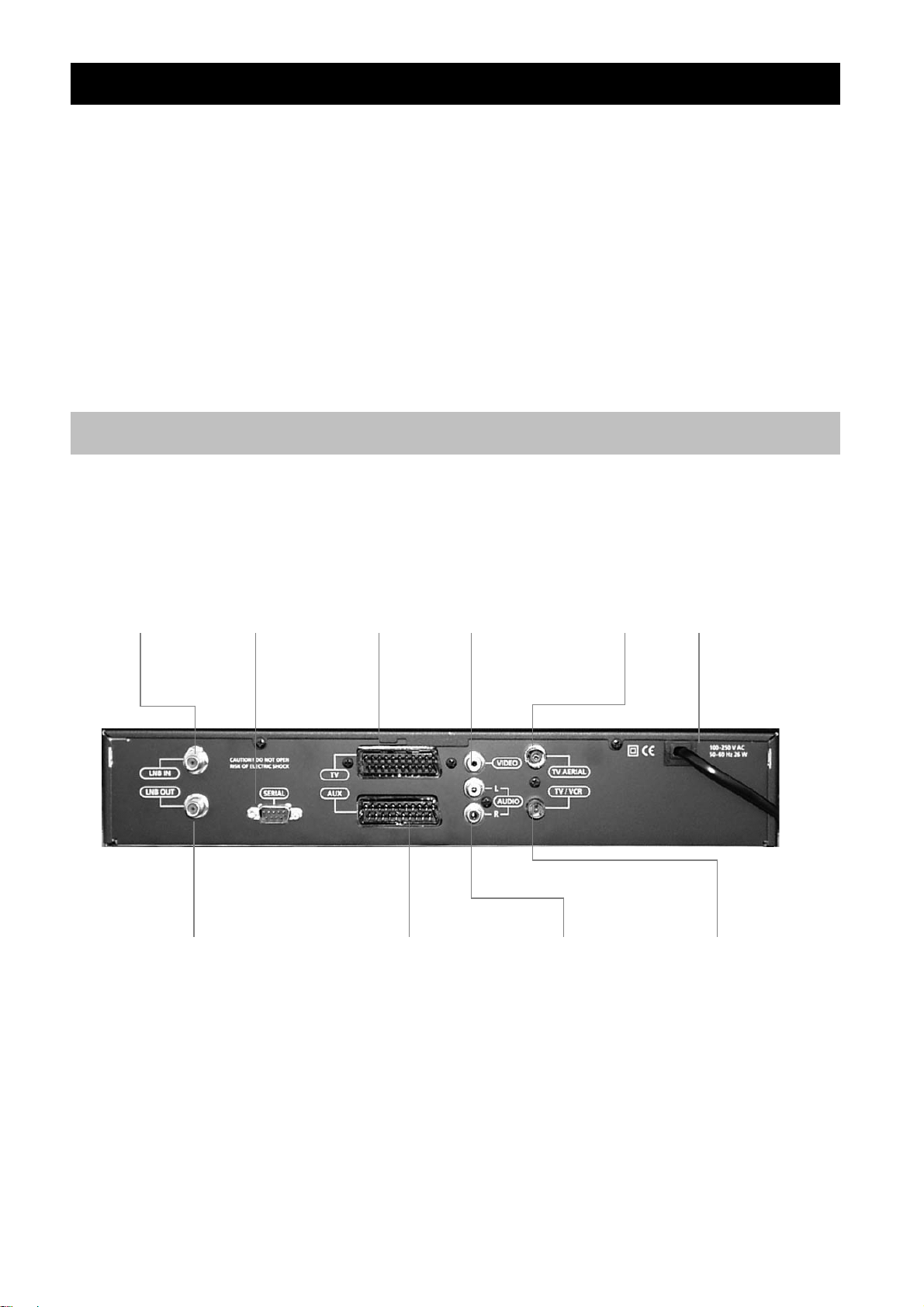
Rear panel
LNB input
Satellite dish
input
(F-connector).
RS232
For a PC.
TV SCART
For the audio
/video input of the
TV set.
IDEO OUTPUT
Composite video
signal output for a
TV set.
TV AERIAL
For a terrestrial
(conventional)
TV aerial.
POWER CABLE
230 V AC
50 Hz
LNB output
Satellite signal (IF) output
with loop through. For
connection to the other
satellite receiver if needed.
GB 4
AUX SCART
For connection to a
VCR or an analogue
satellite receiver.
AUDIO L R
Stereo outputs for
connection to a HiFi
system.
TV/VCR
For an RF-Cable
to the aerial
input of the TV
or VCR.
Page 5
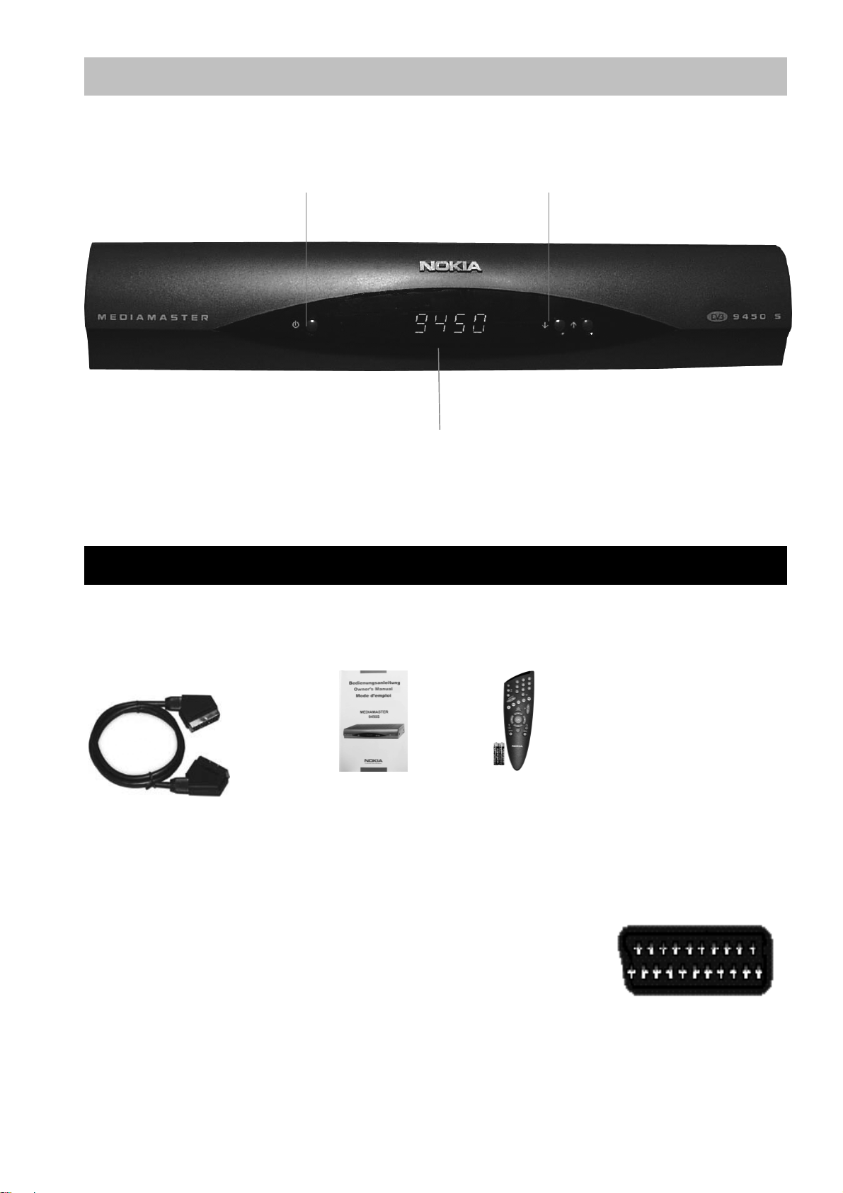
Front panel
Power
To turn the receiver
on/off (standby).
Display
Shows channel number, remote control signal and time in standby mode.
At start up, it displays the model number.
Up/Down
Select channel number,
up/down.
INSTALLATION OF THE MEDIAMASTER
The box for your Mediamaster should contain the following items:
Mediamaster 9450S includes
SCART-Cable
About the SCART sockets
The rear panel of the Mediamaster is equipped with 2 SCART sockets.
When you connect other products to any of these sockets, always
use fully featured SCART cables (as supplied). There are less well
specified SCART cables on the market and picture quality could be
reduced if you use them.
SCART cables are also necessary to get stereo sound from a stereo TV and video recorder.
Owner s
Manual
Remote Controller
and Batteries
GB 5
Page 6
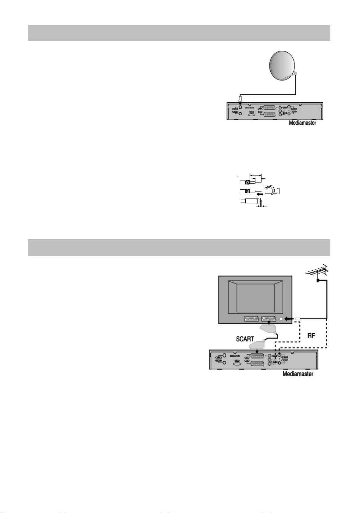
Connecting the Mediamaster to the satellite dish
Installing the satellite dish
Your satellite dish should be installed with a cable for you
to connect to the Mediamaster. If you do not have this cable
you will need to buy one from a dealer (tell the dealer you
need a coaxial cable and F-connectors).
Connect the cable from the satellite dish to the socket
marked LNB IN on the back of the Mediamaster.
If you need to fit the F-connectors onto the cable
Prepare each end of the cable as shown in the diagram.
You will need to fold back the outer braid (as shown).
Slide the F-connector onto the cable, and then turn it
clockwise until it grips the braid.
Ensure that 3 mm of the core is protruding from the end of
the connector.
15mm
8mm
F-connector
3mm
Connecting the Mediamaster to a TV set
There are many different types of TV/VCR and other
equipment that you can connect to the Mediamaster. In this
manual you will see some of the most common ways to
connect your equipment. If you use RF cables you will
have to tune your TV and VCR to the Mediamaster output
channel. If you have problems with your connections and
need help, contact your dealer or Service Provide.
Connect the SCART cable between the main SCART
socket on the TV and the TV SCART socket on the
Mediamaster.
Connect an RF cable from the TV/VCR output on the
Mediamaster to the RF input socket on the TV.
Connect the TV aerial to the TV AERIAL input socket on the Mediamaster.
GB 6
Page 7
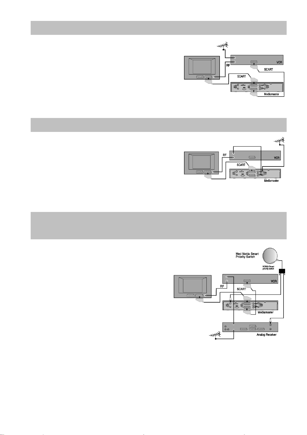
Connecting to a TV and a Video recorder
Refer to your video recorder manual for full instructions.
Connect one SCART cable between the main SCART
socket on the TV and the TV SCART socket on the
Mediamaster.
Connect another SCART cable between the VCR and
the AUX SCART socket on the Mediamaster.
Connect the RF cable from the RF output on the VCR
to the TV aerial input on the TV.
Connect the TV aerial to the RF input socket on the VCR.
If Your VCR does not have a SCART connector
Connect a SCART cable between the main SCART
socket on the TV and the TV SCART socket on the
Mediamaster.
Connect an RF cable from the RF output on the VCR to
the TV aerial input on the TV.
Connect an RF cable from the TV/VCR output on the
Mediamaster to the RF input socket on the VCR.
Connect the TV aerial to the TV AERIAL input socket on the Mediamaster.
Connecting to an Analogue satellite receiver and
a Video recorder
Connect a SCART cable between the main
SCART socket on the TV and the TV SCART
socket on the Mediamaster.
Connect a SCART cable between the VCR and the
AUX SCART socket on the Mediamaster.
Connect an RF cable from the RF output on the
VCR to the TV aerial input on the TV.
Connect an RF cable from the RF output on the
Analogue receiver to the RF input socket on the
VCR.
VCR
Connect the TV aerial to the RF input socket on the
Analogue receiver.
In order to switch the signal from the dish between the analogue and digital receivers, you need a
Universal Twin LNB.
Cable A between output A on the LNB to the LNB socket on the analogue receiver.
Cable B between output B on the LNB to the ANTENNA socket on the Mediamaster.
Both the VCR and the analogue satellite receiver must be tuned to different UHF channels (than the
Mediamaster) when using RF-connectors.
GB 7
Page 8
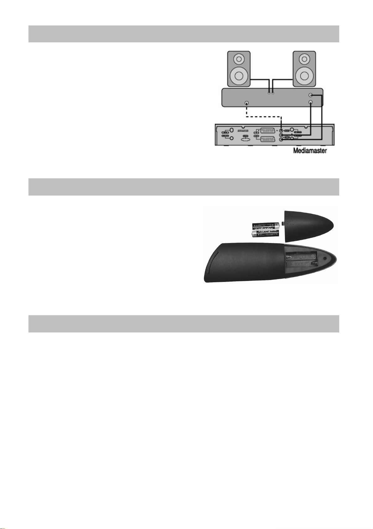
Connecting to Hi Fi system
Connect an RCA/Cinch stereo cable from the AUDIO L R
sockets on the Mediamaster to the LINE, AUX, SPARE or
EXTRA input sockets on your Hi Fi system.
Preparing the remote control
Remove the cover on the battery compartment at
the bottom of the remote control handset.
Insert the 2 x AAA (1,5 V) batteries, as shown in
the diagram, taking care to observe the + and markings indicated inside.
Replace the cover.
Before you continue
Please read this information concerning menus.
A menu is a field of text shown on the TV screen. These menus contain different kinds of information
and give the possibility to select between alternatives. At the bottom of the screen you will normally
also see a short explanation of your options. A menu may contain several lines. Selectable lines are
highlighted. Non-highlighted lines are not selectable.
GB 8
Page 9
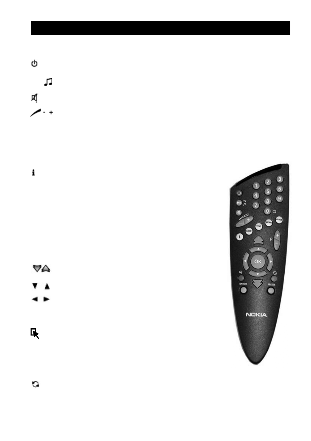
REMOTE CONTROL
This section describes how to operate the Mediamaster using the buttons on the remote control.
Some of the functions can also be carried out using the buttons on the front panel.
Switch the Mediamaster in and out of standby mode.
EXIT TV Return to the viewing mode from a menu without storing settings
(in menu mode).
Switch between TV or Radio (in viewing mode).
Turn the sound off/on (mute).
Adjust the volume of digital programmes.
The Mediamaster s maximum level is controlled by the TV s present volume setting.
0 — 9 Change channel and to select individual menu options.
Note:If 0 is entered as the first digit, the TV Release functionality is activated (see below)
0 TV Release. To switch between digital TV/Radio, analogue TV and analogue satellite TV
and VCR, when your systems are connected by SCART cables.
Info. To display short and extended information (if transmitted)
about current and next programmes.
BACK Go back one level in the menus without storing settings.
TEXT Select teletext information. Press to enter Teletext
(if available).
MENU Show the Main Menu screen.
GUIDE Obtain a list of present and following programmes for the
available channels. This information is only shown if your
Service Provider transmits programme information
(EPG information).
P+ P- Change channels up and down by one unit.
Change page in a menu/list/text if more than one page
is available. To browse through teletext history.
Move up/down in the menus and to change channels.
Change settings in menus
OK Confirm choices and selection of a highlighted item.
To display the TV/Radio channel list.
(Red) Reserved for future application.
OPTION (Green) To select service options in viewing mode.
FREEZE (Yellow) To select the freeze function.
Press once to freeze the screen picture.
Press any other key to go to normal mode again.
(Blue) To toggle between present and previous TV/Radio channels
.
GB 9
Page 10

BASIC SETTINGS
Once you have correctly connected the Mediamaster, you also have to perform some Basic
Settings . During this procedure, helpful information is displayed at the bottom of the menus.
Please note!
The OK button always confirms a selection within these menus, and pressing it will take you to the
next step in the installation process. However, and this is important, often more than one value has to
be entered in a menu. First, perform all necessary settings on the different lines. Then, confirm them
all simultaneously by pressing OK.
You can always go back to the previous menu by pressing the BACK button.
Use the buttons to move upwards and downwards from one line to another. Use to change settings.
You can also use the numeric buttons on the remote control to select a line in a menu and to enter
numeric values.
Tuning procedure when RF connections are used
This procedure is necessary only if your Mediamaster is connected to the TV with an RF
cable.
To tune your TV to the RF signal you might also need your TV manual in addition to this manual. The
steps below explain what to do if you have been unable to use SCART cables in your connection.
Plug in your Mediamaster.
Tuning your TV to the Mediamaster.
Select a channel number on the TV that is not currently used for other TV channels.
Follow the instructions in your TV manual to tune the TV channel selector to UHF channel 43 (this
is the Mediamaster s factory preset UHF channel). If you are already using this channel, select
another non occupied UHF channel between 21to 69 on the TV.
When you have correctly changed the UHF channel number you will see the Welcome menu on
the TV screen. If there is interference from other channels you will have to change the chosen
UHF channel.
Follow the instructions in your TV manual to store this UHF channel as the channel used by your
Mediamaster. You will have to select this channel when you want to watch digital TV/Radio
channels.
Once the welcome message is visible, press the OK button on the Mediamaster s remote control
to start the installation procedure.
If for some reason you have to change the RF channel later, you can do this by using System
Settings menu further on in this manual. If you have a VCR connected it must be tuned to a
different UHF channel (between 21 to 69) than the Mediamaster.
You may now proceed to The Welcome Menu.
GB 10
Page 11

The Welcome Menu
To install the Mediamaster properly you have to adjust a few
settings. You will always be guided by the information at the
bottom of the menus. When you have finished the final part of
the setup procedure you can start watching TV channels and
listening to radio channels. Now you should have the
Welcome Menu on the TV screen. Press the OK button to
proceed.
Language Settings
Select the menu language that you desire. This will define the
language shown in the menus. This will also be the main
language for all the other parts such as audio and subtitling
languages. Press the OK button to proceed.
Installation
In order to configure your equipment (satellite dish and LNB)
you will need to use the following menus.
The LNB is the receiving unit, which is mounted on the satellite
dish. For the following setup procedure you have to know the
Local Oscillator (LO) frequency valid for your LNB(s).
Antenna Satellite Configuration
Highlight Antenna Satellite Configuration and press the OK
button. You can configure the antenna for each satellite from
this menu.
Antenna Alternative:
Select an Antenna alternative from 1 to 16 . Please note, that
the parameters in the menu are pre-programmed, but you can
change any of them to suit your combination.
GB 11
Page 12

Satellite name: From here you can select a name for the configuration.
Switch Type:
There are in principle two kinds of external DiSEqC switches on the market at present. One for
connection of two LNBs. The other one for connection of up to 4 LNBs.
If you have the other switch, defined as DiSEqC, Level 1 or 2 on the market, select DiSEqC 1, 2,
(3 or 4) , for each LNB connected to respective inputs on this switch.
LNB Type:
Selection is possible for different kinds of LNBs. Select the frequency for the LNB, which is valid for
your combination. You may also enter a value with the numbered buttons on the remote control. The
LNB alternatives are: Universal (which is the most common), 5.150 , 9.750 , 10.000 , 10. 050 ,
10.600 , 10.750 , 11. 200 , 11. 475 .
If you have special LNB type, you should select User Define on this menu. And you can enter a new
LNB frequency in the following LNB Frequency menu.
LNB Frequency:
You can enter a special LNB frequency, which is not presented in the LNB Type list as above.
22 KHz Tone Switch:
If you have connected to a Dual LNB or two antennas connected to a 22 KHz tone switch box, set it
to Enable the 22 KHz tone switch.
When you have finished the settings in this menu, press the OK button to save the parameter.
Press BACK to continue with the channel search set-up
(You can also recall this menu later. From the Main Menu; select Installation and then Antenna
Satellite Configuration ).
Automatic Channel Search
Highlight Automatic Channel Search using the down arrow
button on the remote control. Mediamaster has preprogrammed Antenna/Satellite parameters for Astra, HotBird,
Arabsat, NileSat, PanAmsat 4, AsiaSat 2, AsiaSat 3,
TurkSat 1B, TurkSat 1C and Other 1 to Other 7.
Antenna Alternative: Select the option, 1 to 16 , that
corresponds to your antenna system.
Predefined Channel: Each antenna alternative has one or two pre-programmed channel
parameters. Choose a channel from which you want to start the channel search. Normally, each of
the pre-programmed channels gives the same result.
Search Type: Select Free Channels in order to search for free channels only.
Select All Channels in order to search all channels on the satellite.
GB 12
Page 13

Manual Channel Search
You can use manual channel search if you want to add new
channels later. For example If you have a special antenna
configuration which is not assigned in the Antenna
alternative menu, you can add new channels using the
manual channel search function. When you perform a
Manual Search you first need to enter some parameters for the
channel search to work. The information you need to enter in
this menu is available in magazines covering satellite TV
reception, on the Internet or from your Service Provider.
Antenna Alternative: Select Antenna Alternative 1 to 16 that corresponds to the antenna which
you wants to use for the search.
Transponder Freq (MHz): Specify the frequency in GHz. using the numbered buttons on your
remote control. If you enter the wrong number, erase it with the left arrow button.
Polarization: Select polarization; Horizontal or Vertical .
Symbol Rate (Msym/S): Enter the rate with the numbered buttons.
FEC: Enter the appropriate Forward Error Correction (FEC) value or select Auto .
Network Search: Select: Yes to search from all
transponders used by a specific Service Provider.
( Yes is the default setting). Select No to search only from
the transponder that you have entered on the line
Transponder Frequency . (Useful if you do not want to
search through all transponders for a specific program
distributor).
By pressing the OK button you can now enter the channel
search menu where the Mediamaster starts to search for
channels from the satellite.
VIEWING TV
General Information
The following will describe the basic functions of your Mediamaster while watching TV or listening to
radio channels.
Sometimes the information may not be displayed as illustrated. Many of the functions
described here are dependent on the Service Provider and/or can only be used if they are
included in the transmitted programme information.
Please note that during the Channel Search procedure, the Mediamaster has downloaded ALL
available channels. This may include channels from various Service Providers, also those to which
you normally do not have access. If you select a programme to which you do not have access, you
will get the message Service is scrambled or not running on the screen.
GB 13
Page 14

TV Screen Format
If you have a TV set with a 4:3 picture format, and the transmission is in 16:9, you can select 4:3
(Pan & Scan) or 4:3 (Letterbox) to change display format. 4:3 (Pan & Scan) will fill up the
screen vertically, but cut off some information from the left and right sides of the picture. 4:3
(Letterbox) will give a complete picture, but leave black areas at the top and bottom.
You can select the TV screen format in the System setting menu which is a subsidiary of the User
preference menu.
Start/Stop Watching TV
To start the Mediamaster from stand-by mode, press the button or one of the numbered buttons
on the remote control. It is also possible to start by pressing the button on the front of the
Mediamaster. Put the Mediamaster into stand-by by pressing again the button again.
In stand-by mode the display will show the correct time. During viewing the channel number will also
be displayed.
Select Channel
Change channel with the numbered buttons or with the up/down buttons on the remote control.
You can also use the buttons up/down on the front panel of the Mediamaster.
You can also select TV (Radio) channel in the TV (Radio) channel list. See the List of TV Channel
and List of Radio Channel of page 15 and 16.
Program Information. The i Button
Every time you change channel you will receive information for
4-5 seconds about the current programme. This information
includes: Channel number, name, programme title, and time for
present and following programmes. Press
channel. If your Service Provider transmits programme
information you will see: Correct time, a small amount of
information for the current and next programme, the name and
number of the channel, and finally the start and finish time for the programme.
If you want to get more detailed information, press
is shown. You will get extended information (if transmitted) about the current or next programme.
i while watching a
i once more while the information box (banner)
GB 14
Page 15

TV Guide
By pressing the GUIDE button you obtain access to the
TV Guide which gives the titles of the current programmes on
the different channels. By pressing the LEFT or RIGHT button
you also can also obtain information about the next
programme. The minimized viewing window also helps you to
select channels and information. Use the Up/Down buttons to
move the cursor to different programme areas. You can obtain
extended information for a programme by pressing the
i button.
The Radio Button
The display on your Mediamaster and on the TV screen will
show the name of the audio channel you are listening to. While
in audio mode, you can press the i button to get extended
information (if transmitted) about the audio programme.
Return to TV mode by pressing the TV button again.
Volume Level
Increase or decrease the sound level by pressing the
- buttons. A control bar will be displayed at the top of the
screen during level adjustment. (The max. level for volume is
the current volume setting on the TV set). Please note, that the
volume adjustments also change the volume level of to your
VCR during recording. It is possible to turn the sound on and
off with the button. Sound off is indicated with the same
symbol on the screen. If you turn the volume off with this
button, it does not affect the volume of the VCR during recording.
The current volume level will be remembered when you go
to standby mode.
+ and
List of TV Channels
While viewing the TV you can see a programme
list on the screen by pressing the OK button. You can change
to another channel by pressing the UP/DOWN buttons and
then pressing the OK button. To move faster (8 channels at a
time) between channels you can also use the
DOUBLE ARROW buttons.
GB 15
Page 16

List of Radio Channels
While listening to radio Programmes you can see a programme
list on the screen by pressing the OK button. You can change
to another channel by pressing the UP/DOWN buttons and
then pressing the OK button. To move faster (8 at the time)
between the channels you can also use the DOUBLE ARROW
buttons.
Video Recorder
With a Video Cassette Recorder (VCR) connected you can watch/record video tapes.
If your VCR is connected with a SCART cable and you press the start button on the VCR, the
playback will start and interrupt the TV programme from the Mediamaster.
To watch TV programmes again, press the TV button or stop the VCR.
Please note, that during the recording of a programme, everything shown on the screen will be
registered! For example: If you call up a Menu from the Mediamaster on the screen, the menu will be
recorded!
Subtitling and Teletext. The TEXT Button
Pressing the TEXT button once while watching TV enables the teletext output to the TV.
To enable the teletext display on the TV, press the Teletext button on the TV s remote control.
This is only possible if more than one subtitling language is being transmitted. Please refer to the
instruction manual of your TV for the teletext function. Exit the menu by pressing the TV button.
SETTING FROM THE MAIN MENU
Press the MENU button and you will get the Main Menu on the
TV screen. Press the EXIT button to leave the menu.
If you select one of the highlighted titles and press the OK
button, a submenu will be shown on the TV screen. From a
submenu you can adjust settings to your own requirements.
GB 16
Page 17

TV Channels and Radio Channels
TV/Radio Channels will show a list with the names of the
different channels. To move faster within the list, use the
DOUBLE ARROW buttons. Press OK to enter a marked
channel.
TV Guide and Radio Guide
These guides will give you an overview of programme
information from the TV/Radio channels. Step to different
channel numbers with the UP/DOWN buttons. If you stop on a
highlighted line and press OK, you will exit the menu and enter
the highlighted channel. Select information about the next
programme with the RIGHT button. Use the i button to get
extended information about a marked programme.
Please note, that information will only be shown if it is included in the transmission.
Edit Channels
From this menu, you can rename favorite lists, add channels,
remove channels and arrange the channels in a preferred
order.
The All TV list displays all channels, which you captured from
the channel search operation in the installation menu
The All TV list can contain hundreds of channels. By creating
your own favorite lists you can make channel handling a bit
more convenient.
GB 17
Page 18

Rearrange List
If you have created several Favorite lists you can
determine the sequence in which the lists will appear. To
rearrange channels, select the list which you want to
move using the OK button. Move the channels to the desired
position using the UP/DOWN button and press OK.
Rename List
You can change the list name with the virtual keyboard
on the screen. Type in the text you want using the remote
control arrow keys. Please note that the All TV , All Radio ,
Free TV and Free Radio can not be changed.
Delete the existing characters by pressing OK on the left arrow
key of the keyboard. Select the characters using the LEFT and
RIGHT buttons. Press the OK button to enter the text selected.
To save the renamed list, press the BACK button.
To select various characters, press OK on the page UP/DOWN box of the keyboard.
Add Channels
From here you can create your own favorite lists, containing the
channels you watch most frequently. You can give each list a
specific name in the Rename List menu. When a favorite list is
selected, you see only those channels defined in the list. You
can add channels to your Favorite Lists from the All TV , All
Radio , Free TV and Free Radio list. A channel is added by
pressing the OK button. The V marking to the right on a line
contains added channels.
Lock Channels
To get to this menu you need an access code. The default
access code is 1234 . From here you can lock (and later
unlock) channels in any of the lists in order to prevent e.g. your
children from watching. Select the channel you want to lock
and press the OK button. A locked channel will be marked with
a padlock symbol. Repeat the procedure for each channel you
want to lock. When you lock a channel in any list, the channel
will automatically be locked in all other lists When watching TV, you will be asked to enter your
access code before you can watch a locked channel.
GB 18
Page 19

Rearrange Channels
You can arrange the order of channels within your favorite lists.
To rearrange channels, select the channel which you want to
move using the OK button. Move the channels to the desired
position using the UP/DOWN button and press OK.
Remove Channels
From here, when the All TV list is selected in the Edit
Channels menu, you can remove channels.
Please note. Channels deleted this way will be
permanently removed. The only way to get them back is to
perform a new channel search.
To remove channels:
Select the channel that you want to delete and press OK. You
will be asked if you really want to remove it. If so confirm by
pressing OK once more. If not, press BACK.
USER PREFERENCES
From here you can change the menu language. You also have access to the Parental Control and
the Appearance menus.
Parental Control
By pressing OK on the line Parental Control you will be
requested to enter your access code. (Personal Identification
Code).
This code is set to 1234 by the factory. You will then get the
menu from where you can lock some functions in the
Mediamaster.
Receiver lock
If you select On , you will have to enter the access code every time you start the Mediamaster from
stand-by.
Lock Installation Menu
If you select On , you will have to enter the access code every time you enter the installation menu.
Age Limit
If you want everybody to have access to all available types of programmes, select Off .
If you select On , you may block programmes unsuitable for children. Select an age limit between 4
and 18 years on the line that appears.
However, you should be aware that not all Service Providers have the necessary codes for these
functions implemented in their transmissions.
GB 19
Page 20

Change access code
From here you can change the access code from the standard 1234.
DO NOT FORGET IT! Without it you do not have access to any of the functions where the code
is required!
If you forget it, you have to contact an Authorized Nokia Service Center to get help.
Language Settings
From here you can change the language for the menus, main
audio language and alternative audio language.
System Settings
From here you can adjust settings concerning your TV.
TV Screen Format: Select your TV screen format.
The 4:3 format is the standard format for most TV screens.
Select 16:9 for a wide screen TV.
Output Selection: If the teletext function does not work when
watching channels from an analogue satellite receiver
connected to the Mediamaster, change this setting from RGB to Composite .
UHF Channel Number: Select this alternative if you have to change the RF channel.
If you change the RF channel number, you must also change it to the same value on the TV. If you
do not, the picture will become black.
RF Modulator Type: If the Mediamaster is connected to the TV by an RF cable, you can select the
RF modulator type. The RF Modulator affects a channel s audio. If you get picture but no sound, the
RF modulator selection might be wrong. Select UK (PAL I) if the Mediamaster is used in the UK.
Select Normal if it is used elsewhere.
Information Box Timeout (secs): When you switch channels, an information banner will be shown
for a few seconds. You can select for how long the banner will be shown.
Display Volume Indicator: Select whether or not you want the volume bar to appear on the screen
when you change the volume.
Date Setting (dd/mm/yyyy): Used to set the current date, month and year.
Time Setting: Adjust the clock.
GMT Offset: Adjust the time difference in your country.
GB 20
Page 21

On/Off Timer Setting
You can enjoy this On/Off Timer for such a convenience as
wake-up or automatic VCR recording. Mediamaster will be
automatically switched-on and play specified channel for the
specified time, and then switched-off.
You may specify up to 8 separate lists with turn-on time, date,
duration, channel and occurrence options.
Time Setting
You can select the operation mode of the On/Off timer by
pressing LEFT/RIGHT button on the remote control.
Once: The Mediamaster will be switched-on/off for the
specified time only once.
Daily: The Mediamaster will be daily switched-on/off for the
specified time.
Weekly: The Mediamaster will be weekly switched on/off for
the specified time.
Off: Cancel the operation of On/Off timer.
Channel Name: You can select channel from the TV or Radio list by pressing LEFT/RIGHT button
on the remote control.
Select a channel you want to play and press OK.
On Time: You can select time, date or day depending on your selection in "Time Setting" menu. The
Mediamaster will be switched-on at the On time .
Duration (hh:mm)˚: Mediamaster will keep playing for the time specified in this "Duration".
For example, if you set 00:30, Mediamaster will be switched-off 30minutes after switched-on.
GAME
SOKOBAN
To start the game, select the game level by using the LEFT and RIGHT button and press OK button
on the remote control. You can control the segment by LEFT/RIGHT/UP/DOWN button on the remote
control. To finish the game, press EXIT or BACK button on remote control
.
GB 21
Page 22

INSTALLATION SUBMENUS
Select this Menu from the line Installation in the Main Menu.
The submenu will give you the opportunity to change the
preferences performed during first time installation.
You can also add features that were not included in the first
installation. Please note that helpful information for every line is
given at the end of the menu.
Antenna Satellite Configuration
Please refer to page 11.
Automatic Channel Search
Please refer to page 12.
Manual Channel Search
Please refer to page 13.
Advanced Channel Search
The information needed to enter in this menu is available
in magazines covering satellite TV reception, or from your
Service Provider.
Antenna Alternative: Select the satellite from which the
signal is to be received.
Transponder Freq(MHz): Enter using the numbered
buttons on the remote control.
Polarization: Select Horizontal or Vertical .
Symbol Rate(Msym/s): Enter with the numbered buttons.
FEC: Select Auto or the appropriate Forward Error Correction (FEC) value using the left/right
button on the remote control.
Video PID: Enter the PID (Packet Identifier) for the video signal.
Audio PID: Enter the PID for the audio signal.
PCR PID: Enter the PID for the PCR (Programme Clock Reference).
GB 22
Page 23

Reinstall
This will start the Installation procedure from the Welcome
Menu .
When you press OK in the Welcome Menu again,
be aware of the fact, that all previous channels and
settings will be erased! To exit the Reinstall menu
without erasing any channels, press Back .
System Information
This gives general information about which hardware
and software version your Mediamaster is running on.
GB 23
Page 24

GLOSSARY OF TERMS
AGC
Acquisition Gain Control.
BER
:Bit Error Ratio.
DiSEqC
Digital satellite Equipment Control.
The outdoor unit comprises the antenna, one or
more LNBs polarizers and external components.
DVB
The Digital Video Broadcast group was created to
establish a technical frame work for the
introduction of digital video broadcasting systems.
EPG
Electronic Programme Guide. A software that
enables viewers to navigate easily among the
large number of channels provide by digital
technology, in order to select the service they
desire.
FEC
Forward Error Correction. Correction of faulty bits
in the received signal.
GHz
The prefix giga means billion, and Hertz means
cycles per second. Signal in the GHz range are
often called microwaves.
LNB(Low Noise Block converter)
An electronic unit mounted on the satellite dish. It
recovers the signals reflected by the dish and
converts them to signal that can be used the
mediamaster
MHz
The prefix mega means million, and Hertz means
cycle per second.
Medimaster
A unit that converts the digital satellite signal into
audio and video signals. The audio and video signal
can be send to the TV set either via SCART or via
RF(modulator output).
MPEG
Moving Picture Experts Group. Body established
by the international Standards Organization to
provide the basis for a picture coding and
Compression system.
.
Network
A number of digital channels transmitted from one
source. Grouped under separate headings in the
channel list.
Parental control
A feature that allows parents to lock: programmes
that they consider unsuitable for children. A locked
channel or programme can only be unlocked with
the special parental access code.
ACCESS code
Personal Identification Number. A four -digit code
stored in the memory. You can change ACCESS
code on the User Preference Menu.
Polarization
Polarization allows several programmes to be fit
into the same frequency band. The signal from the
satellite are transmitted either with linear (Vertical or
Horizontal ) polarization or circular (right or left)
polarization.
RF
Radio Frequency(known as HF in some countries).
SERIAL RS232
A serial communication standard data port.
Satellite dish
A dish-shaped antenna (reflector) that receiver
signals from a satellite. The dish focuses the signals
into the LNB.
SCART
A 21-pin connector used for connecting the
Mediamaster, VCR and TV. Also named
Euroconnector or Peritel connector.
Symbol rate
Size of the digital package transmission.
S.W
Software. Program code.
PID:Packet Indentifier.
PCR:Program Clock Reference.
GB 24
Page 25

PROBLEM SOLVING
Problem Possible causes What to do
The display on the
front panel does not
light up/is not lit.
No sound or picture. The satellite dish is not pointing
Bad picture/blocking
error.
Mains lead is not connected. Check that the mains lead is
plugged into the power socket.
Adjust the dish. Check the signal
at the satellite.
No signal or weak signal.
The LNB is faulty.
The satellite dish is not pointing at
the satellite.
Signal too strong.
Satellite dish is too small.
LNB noise factor too high.
The LNB is faulty.
level indicator in one of the channel
search submenus.
Check the cable connections, LNB
and other equipment connected
between the LNB and the receiver, or
adjust the dish.
Replace the LNB.
Adjust the dish.
Connect a signal attenuator to the
LNB input.
Change to a larger dish.
Change to an LNB with lower noise
factor.
Change the LNB.
There is no Welcome
menu on the screen
after you switched on
the Mediamaster for
the first time.
There is interference
on your digital satellite
channels, an existing
terrestrial channel or
video signal.
You made a video
recording of a digital
satellite channel and
the whole or parts of
the programme were
not recorded.
The system is connected by
SCART cables and the TV is not
in AV/EXT mode.
The system is connected by RF
cables and the TV is not set to the
channel tuned for digital satellite
TV.
The system is connected by RF
cables and the output channel of
the Mediamaster interferes with an
existing terrestrial channel or
video signal.
The Mediamaster was not left on
the appropriate channel.
The system is connected by
SCART cables and the VCR is not
in AV/EXT mode.
If the system is connected by SCART
cables, switch the TV to the
appropriate AV input.
If the system is connected by RF
cables, switch the TV to the channel
for digital satellite TV. If you have not
tuned in the TV you may do this first.
Please see the TV manual for
instructions. You can also change the
RF-channel in the Mediamaster.
See TV settings.
Change the Mediamaster output
channel to a more suitable channel
between 21-69, or connect the system
by SCART cables.
If you make a recording from digital
satellite TV your Mediamaster has to
be left on the channel you want to
record.
If the system is connected by SCART
cables, switch the VCR to appropriate
AV input.
The system is connected by RF
cables and the VCR is not set to
the channel tuned for digital
satellite TV.
If the system is connected by RF
cables, switch the VCR to the channel
for digital satellite TV. If you have not
tuned in the VCR you may do this first.
Please see the VCR manual for
instructions.
GB 25
Page 26

TECHNICAL SPECIFICATION
Transmission Standards DVB, MPEG 2
LNB/Tuner input
Connector 2 x F-type
(Loop Through)
Input frequency 950-2150 MHz
Max Current 500 mA max
Supply Voltage 13 V/18 V
DiSEqC 1.0
RF Impedance 75 Ohm
Demodulator
QPSK
Symbol rate 2-45 Msym/s
SCPC and MCPC
Video decoder
MPEG-2 Main Profile @ Main Level
Data rates up to 15 Mbit/s
Video formats 4:3 (letterbox),
4:3 (Pan & Scan)
16:9
Audio decoder
MPEG-2 layer 1 & 2
Stereo, Mono, Dual channel, Joint stereo
System resources
Processor 108 MHz MIPS 32bits
CPU RAM 2 Mbytes
MPEG RAM 2 Mbytes
Flash ROM 2 Mbytes
Resolution 720 x 576
OSD 16 colours
RF Modulator
Output Channel 21-69
Output Signal PAL B/G/I
Input/Output Connectors IEC169-2 male/female
Preset Channel 43
TV SCART
RGB, CVBS, Audio
AUX SCART
CVBS, Audio
Audio Output
Hi-Fi 2 RCA Jack
Serial Data
9-pin D-sub RS232C signal
Baud rates 15200baud max
Remote Controller
Type RC 4661
Operating distance 10 meters
Batteries 2 x 1,5V AAA
Rear Panel Interfaces
LNB IF IN/OUT
RF modulator IN/OUT
2 x SCART for TV and AUX
2 x RCA Audio (L/R)
1 x RCA Video (CVBS)
RS 232C (9-pin D-Sub)
General Data
Operating Temperature 10 °C to 45°C
Storage temperature -40°C to +70°C
Supply Voltage 96-264 V AC,
48 Hz-60 Hz
Power Consumption Max 26 W
at 500 mA LNB Load
Power Consumption in
Standby 8 W
Dimension (W x D x H) 380 x 270 x 70 mm
Weight 3.4 Kg
GB 26
Page 27

MENUS SCREEN STRUCTURE
First Time Installation
Welcome
Menu
Main Menu
1.TV Channels
2.Radio Channels
3.TV Guide
4.Radio Guide
5.Edit Channels
6.User Preferences
7.Game
8.Installation
Language Settings
1.Menu Language
2.Main Audio Lang
3.Alternative
4
1.TV Channels
<ALL TV>
1.NRK
2.CNN
3.TV3
4.TV4
5.....
Installation
1.Antenna Satellite..
2.Automatic Chann..
3.Manual Channe
4
2.Radio
Channels
<ALL Radio>
1.Hitliste
2.CNN Radio
3.TV4
4.......
Antenna Satellite
Configuration.
1.Antenna Alternative
2.Satellite Name
3.Switch ..
4
3.TV Guide
<Free TV>
1.NRK
2.CNN
3.TV3
4.TV4
5.....
Automatic
Channel
Search.
1.Antenna..
2.Predefine.
3..
4.Radio Guide
<Free Radio>
1.Hitliste
2.CNN Radio
3.TV4
4.......
5.Edit Channels
<All TV>
1.Rearrage List
2.Rename List
3.Add Channels
4.Lock Channels
5.Rearrange Channels
6.Remove Channel
On/Off Timer Setting
<On/Off Time List>
1.Timer Defined
2.Timer Defined
3.
8.Timer Defined
6.User Preference
1.Parental Control
2.Language Settings
3.System Settings
4.On/Off timer Settings
Parental Control
1.Receiver Lock
2.Lock Installation Menu
3.Age Limit
4Change Access Code
Language Settings
1.Menu Language
2.Main Audio Language
3.Alternative Audio
Language
4.Display Subtitles
5.Main Subtitle Language
6.Alternative Subtitle
Language
System Settings
1.TV Screen Format
2.Output Selection
3.UHF Channel Number
4.RF Modulator Type
5.Information Box Time out
6.Display Volume Indicator
7.Date Setting(dd/mm/yyyy)
8.Time Setting(hh:mm)
9.GMT Offset
ReinstallSystem Information
7.Game
8.Installation
1.Antenna Satellite Configuration
2.Automatic Channel Search
3.Manual Channel Search
4.Advancd Channel Search
5.Reinstall
6.System Information
Antenna Satellite Configuration
1.Antenna Alternative
2.Satellite Name
3.Switch Type
4.LNB Type
5.LNB Frequency
6.22KHz Tone Switch
Automatic Channel Search
1.Antenna Alternative
2.Predefined Channel
3.Search Type
Manual Channel Search
1.Antenna Alternative
2.Transponder Freq(MHz)
3.Polarization
4.Symbol Rate (Msym/S)
5.FEC
6.Network Search
Advanced Channel Search
1.Antenna Alternative
2.Transponder Freq(MHz)
3.Polarization
4.Symbol Rate (Msym/S)
5.FEC
6.Video PID
7.Audio PID
8.PCR PID
GB 27
Page 28

Nokia is a registered trademark of Nokia Corporation
www.nokia.com
66 76967-11
KQX1A644Z
 Loading...