

Page 1

PAMS Technical Documentation
NSM–3/3D Series Transceivers
Tuning Instructions
Issue 4 02/2002 Nokia Corporation
Page 2

NSM–3/3D
Tuning Instructions
CONTENTS
PAMS Technical Documentation
Page 2
Nokia Mobile Phones Ltd.
Issue 4 02/2002
Page 3

PAMS Technical Documentation
Tuning Instructions
General
All tuning operations are carried out using the service software. The service software turns the phone into the locals mode, in which the phone
can be outwardly controlled via the MBUS interface.
Tuning is based on the software communicating with the D/A and A/D
converters of the phone. In some instances the phone processor will also
calculate the required correction parameter.
The tuning values of the phone reside on the EEPROM. The contents of
the EEPROM can be read by the service software and saved as a file.
This is advisable when there is need to retain that information, e.g. in
view of replacement of the circuit. The program also enables writing the
default parameters on the EEPROM, in which case all tuning steps should
be carried out.
NSM–3/3D
Tuning Instructions
During tuning, proceed as follows:
– Take care not to damage sensitive measuring instruments with exces-
sive RF power.
– Carry out all tuning steps in the shortest possible time to avoid exces-
sive heating of RF units.
– Perform all tuning steps in the order presented.
– Never try to mask a fault by tuning it out!
Issue 4 02/2002
Nokia Mobile Phones Ltd.
Page 3
Page 4

NSM–3/3D
Tuning Instructions
Required Equipment
– PC with service software; see separate section for instructions on
installation and use.
– Service accessories; see equipment setup pictures.
– Multimeter or DVM.
– GSM radio telephone test station or separate measuring equipment as
follows:
– RF generator
– pulse power meter
– spectrum analyzer
– attenuator and branching unit
Equipment Setup
PAMS Technical Documentation
Caution: Make sure that you have switched off the PC and the printer
before making connections !
Caution: Do not connect the PKD–1 key to the serial port. You may
damage your PKD–1 !
Attach the protection key PKD–1 to parallel port one (25–pin female
D–connector) of the PC. When connecting the PKD–1 to the parallel port
be sure that you insert the PC end of the PKD–1 to the PC (male side). If
you use a printer on parallel port one, place the PKD–1 between the PC
and your printer cable.
Next connect the M2BUS service cable, DAU–9S, to the serial port
(RS–232) of the computer. Attach one end of the service cable to the PC
serial port and the other end to the service box, JBU–6. For servicing the
phone with the covers in place the service box should always be used.
When the phone covers are removed the jigs should be used.
Page 4
Nokia Mobile Phones Ltd.
Issue 4 02/2002
Page 5

PAMS Technical Documentation
Tuning Instructions
Equipment Setup for Testing Audio and Charging
DC Unit
Oscillator
NSM–3/3D
6.
7.
5.
2.
8.
9.
1. 3.
4.
Item: Service accessory: Product code:
1 Service Box JBU–6 0770153
2 RF Adapter RL6 for JBU–6 0770172
3 DC Power Cable PCS–1 0730012
4 Service MBUS Cable DAU–9S 0730108
5 DC–DC Cable SCB–3 0730114
6 Software protection key PKD–1 0750018
7 Audio Box JBA–6 0770184
8 Audio Cable ADS–3 0730197
5 Service SW diskette 3.5” for WinTesla 0774046
9 Service SW diskette 3.5” for NSM–3 (3D) 0774080
Issue 4 02/2002
Flash SW packages on CD 0775219
Nokia Mobile Phones Ltd.
Page 5
Page 6

NSM–3/3D
Tuning Instructions
Flash Concept with JBU–6
PAMS Technical Documentation
11.
13.
1.
6.
5.
2.
Item: Service accessory: Product code:
14.
12.
10.
9A.
7.
9B.
3.
4.
8.
1 Service Box JBU–6 0770153
2 Flash Loading Adapter FLA–7 0080326
3 Flash Security Box TDF–4 0770106
4 Prommer FPS–4S 0085095
5 DC Power Cable PCS–1 for JBU–6 0730012
6 Service Cable XMS–3 0730174
7 D15 – D15 Cable AXS–5 0730091
8 Printer Cable (Included in FPS–4 sales pack) 0730029
9A D9 – D9 Cable AXS–4 0730090
(Included in FPS–4 sales pack)
9B D9 – D9 Cable AXS–4 0730090
10 DC Cable PCC–1B 0730053
11 Software protection key PKD–1 0750018
12 Service SW diskette 3.5” for NSM–3 (3D) 0774080
Service SW diskette 3.5” for WinTesla 0774046
13 Travel Charger ACH–6E (Euro) 0270381
Travel Charger ACH–6U (USA/Japan) 0270382
Travel Charger ACH–6X (UK) 0270380
14 AC Charger ACL–3E 0680015
(Included in FPS–4 sales pack)
Page 6
Nokia Mobile Phones Ltd.
Issue 4 02/2002
Page 7

NSM–3/3D
PAMS Technical Documentation
NOTE: Changes in Sales Packs
In FPS–4S sales pack ACL–3E will be replaced by AXD–1 power cable.This cable
makes it possible to power the FPS–4 prommer with ACH–6 type charger. Same
charger has been used to power TDF–4 Flash Security Box and it must be purchased separately.
AXD–1 power cable will be added to FLA–7 sales pack. This makes it possible to
power FLA–7 from TDF–4 power output or separate ACH–6 type charger.
Tuning Instructions
Flash Concept Power Distribution Options
1. Two AXD–1 cables and two ACH–6 chargers – RECOMMENDED!
2. One ACH–6 and two ACL–3 chargers
1. Power distribution with two AXD–1 cables and two ACH–6 chargers:
FLA–7 powered by AXD–1 cable from TDF–4 “Power Out” connector
(It is also possible to power FLA–7 with AXD–1 and
TDF–4 powered by ACH–6 Charger.
FPS–4 powered by AXD–1 DC cable and ACH–6 Charger.
separate
ACH–6).
NOTE: Do not use SCF–7 cable to power FLA–7 and FPS–4 from one ACH–6 charger as done when using ACL–3!
Issue 4 02/2002
Nokia Mobile Phones Ltd.
Page 7
Page 8

NSM–3/3D
Tuning Instructions
2. Power distribution with one ACH–6 and two ACL–3 chargers:
FLA–7 powered by ACL–3 charger
TDF–4 powered by ACH–6 charger
FPS–4 powered by ACL–3 charger
PAMS Technical Documentation
NOTE: It is recommended to use separate power supplies for FLA–7 and FPS–4.
Page 8
Nokia Mobile Phones Ltd.
Issue 4 02/2002
Page 9

PAMS Technical Documentation
Tuning Instructions
Testing Without Covers – Using Test–frame MJS–9
NSM–3/3D
6.
1.
4.
2.
5.
3.
Item: Service accessory: Product code:
1 Module Jig MJS–9* 0750154
2 Service MBUS Cable DAU–9S 0730108
3 ACP–8 Travel Charger
(see code: General Information chapter)
7.
4 RF Antenna Cable XRF–1 0730085
5 DC Power Cable PCS–1 0730012
6 Software Protection Key PKD–1 0750018
7 Service SW diskette 3.5” for WinTesla 0774046
*) The nominal operating voltage for MJS–9 is 8.0 V.
Issue 4 02/2002
Service SW diskette 3.5” for NSM–3 (3D) 0774080
Flash SW packages on CD 0775219
The supply voltage for MJS–9 must never exceed 15.0 V
Nokia Mobile Phones Ltd.
Page 9
Page 10

NSM–3/3D
Tuning Instructions
Flashing With FLA–10
11.
PAMS Technical Documentation
9.
12.
10.
8.
7A.
1.
7B.
5.
6.
14.
13.
2.
8.
3.
4.
Item: Service accessory: Product code:
1 Service Flash Adapter FLA–10 (Sales Pack) 0081346
2 Flash Loading Adapter FLA–7 0080326
3 Flash Security Box TDF–4 0770106
4 Prommer FPS–4S 0085095
5 D15 – D15 Cable AXS–5 0730091
6 Printer Cable (Included in FPS–4 sales pack) 0730029
7A D9 – D9 Cable AXS–4 0730090
(Included in FPS–4 sales pack)
7B D9 – D9 Cable AXS–4 0730090
8 DC Cable PCC–1B 0730053
9 Software protection key PKD–1 0750018
10 Service SW diskette 3.5” for NSM–3 (3D) 0774080
Service SW diskette 3.5” for WinTesla 0774046
11 Travel Charger ACH–6E (Euro) 0270381
Travel Charger ACH–6U (USA/Japan) 0270382
Travel Charger ACH–6X (UK) 0270380
12 AC Charger ACL–3E
13 Service Cable XMS–3
14 DC Power Cable FLC–2
(Included in FPS–4 sales pack) 0680015
(XCM–5 included in FLA–7 Sales Pack) 0730174
(Included in FLA–10 Sales Pack) 0730012
Page 10
Nokia Mobile Phones Ltd.
Issue 4 02/2002
Page 11

PAMS Technical Documentation
POS Flash Concept with FLA–10
6.
NSM–3/3D
Tuning Instructions
4.
5.
1.
3.
Item: Service accessory: Product code:
1 Flash Loading Adapter FLA–10 0081346
2 Service Cable XMS–3 0730174
3 Travel Charger ACP–8
4 D9–D9 Cable AXS–4 0730090
5 POS Flash Adapter FLS–2D 0774170
6 Service SW diskette 3.5” for NSM–3 (3D) 0774080
Flash SW packages on CD 0775219
2.
(see code: General Information chapter)
Issue 4 02/2002
Nokia Mobile Phones Ltd.
Page 11
Page 12

NSM–3/3D
Tuning Instructions
Warranty Transfer
PAMS Technical Documentation
DC
3.
3.
1.
Item: Service accessory: Product code:
1 Flash Loading Adapter FLA–10 0081346
2 Service Cable XMS–3 0730174
3 DC Power Cable FLC–2 0730185
2.
1.
Page 12
Nokia Mobile Phones Ltd.
Issue 4 02/2002
Page 13
PAMS Technical Documentation
Tuning Steps
NOTE: All RF Tunings are made in Test Jig MJS–9.
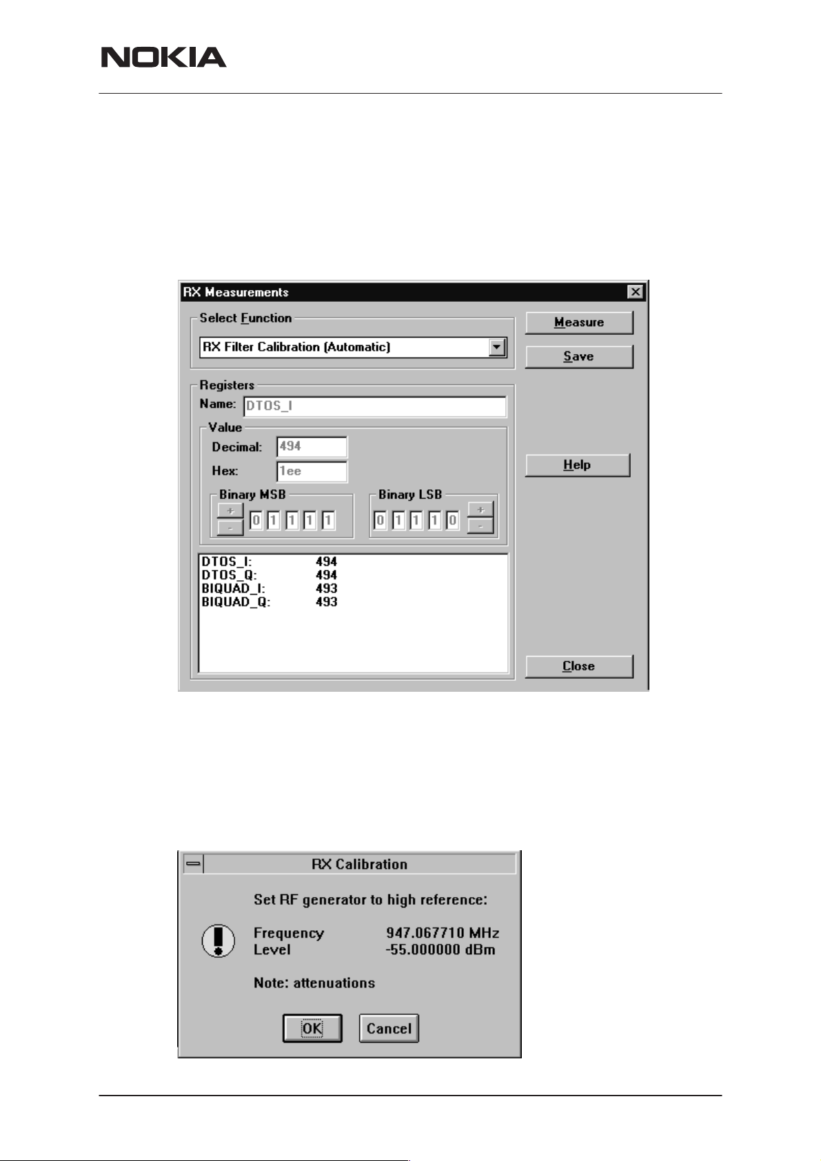
1. RX Filter Calibration
BB–filter tuning is fully internal operation. External signal generators etc. are
not needed, only command for phone to execute filter calibration procedure.
NOTE: RX Filter Calibration is needed when N505 has been changed.
NSM–3/3D
Tuning Instructions
2. RX Calibration (AGC + AFC)
Procedure
Follow the steps described in chapter ”Service Software Instructions” section ”RX calibration... command”.
The measurement is done in five steps: 1. User is requested to put signal
generator to high input level (read from .INI file).
Issue 4 02/2002
Nokia Mobile Phones Ltd.
Page 13
Page 14
NSM–3/3D
Tuning Instructions
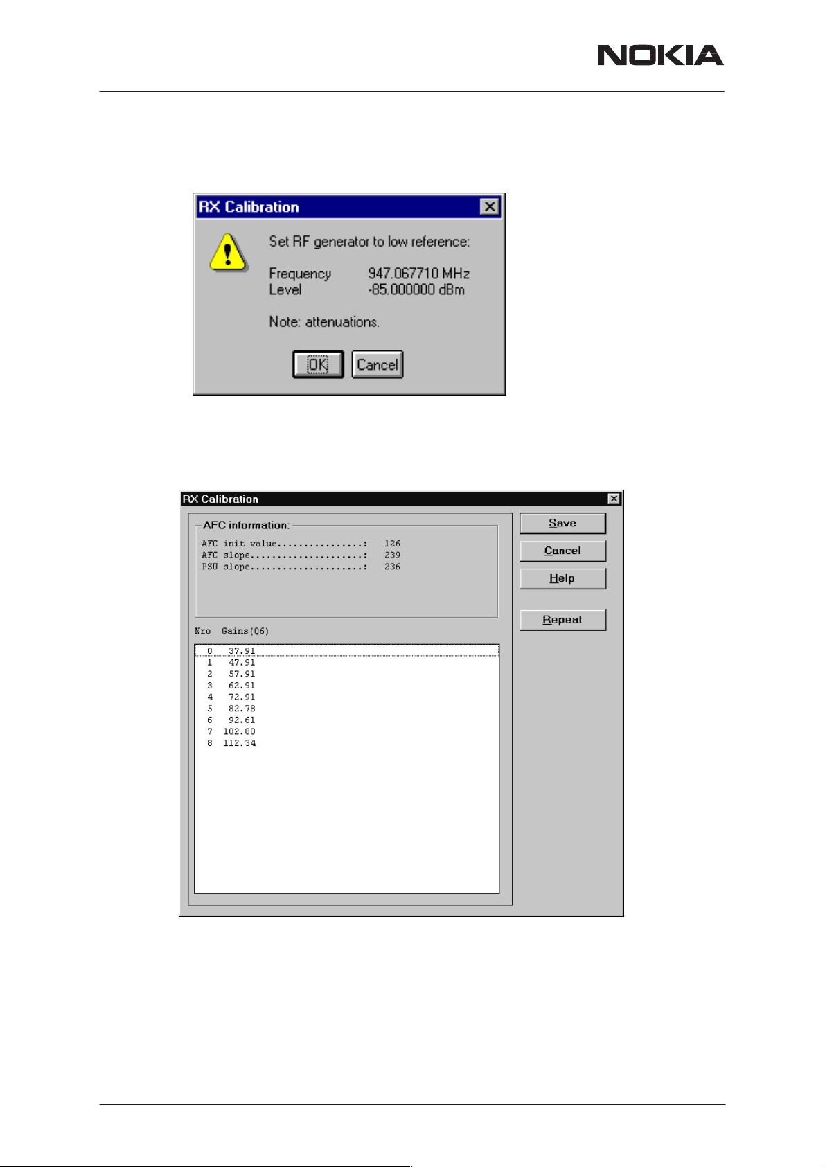
2. Measurement with high input level is executed
3. User is requested to put signal generator to low input level (read from
.INI file).
4. Measurement with low input level is executed
5. The RX Calibration dialog will be updated when previous steps are
done.
PAMS Technical Documentation
Page 14
Software reports the following:
AFC init value
AFC slope
PSW slope
Gain step values
Nokia Mobile Phones Ltd.
Issue 4 02/2002
Page 15

PAMS Technical Documentation
Limits for the reported values
After the calibration reported values should be approximately following:
Parameter Low limit High limit
AFC init value –200 200
AFC slope 135 345
PSW slope For information
Gain step values EGSM (nominal) PCN (nominal)
0 37 28
1 47 38
2 57 48
3 62 53
4 72 63
5 82 73
NSM–3/3D
Tuning Instructions
6 92 83
7 102 93
8 112 103
Troubleshooting
If the calibration does not succeed the software normally reports ”Unable
to read data from phone” or ”Failed to set high reference” or ”Failed to set
low reference”.
In this case check first the basic functionality of the receiver chain: RF
generator frequency set as in the calibration and level for example to the
high reference value.
Then go to the RSSI reading menu (under RF controls). If the reading is
very low there is something broken in the receiver and must be found by
measuring voltages and signal levels at different places (information of
these can be found elsewhere in this manual).
If the RSSI reading seems to be within 5 - 10 dB the same as the RF input level check that the VCTCXO frequency is close enough the wanted
frequency. This is most easiest done by measuring VCO frequency in
GSM middle channel 60 (VCO frequency is be 3788 MHz). If the deviation is bigger than about +/–50 kHz it is probable that the VCTCXO is not
operating correctly.
If both of these (RSSI reading and the frequency) seem to be correct and
calibration still fails the most probable reason is that there must be some
missing gain step in Hagar or then the problem must be in Coppa.
Issue 4 02/2002
Nokia Mobile Phones Ltd.
Page 15
Page 16

NSM–3/3D
Tuning Instructions
3. AM suppression tuning
This operation is recommended when RX components have been
changed (between N505/Hagar and Z670/antenna switch).
AM suppression calibration is for tuning four Hagar parameters to get as
small RSSI value as possible.
For AM–suppression calibration external signal generator with AM–modulation is needed.
PAMS Technical Documentation
Select
Am Suppression...
from
Tuning
menu.
Page 16
Signal generator setup:
AM–modulation, fmod = 1 kHz, mod. depth = 83%
f = ch(default)+10 MHz,
P = –23 dBm (EGSM)
P = –26 dBm (PCN)
Press
Press OK button.
Measure
button.
Nokia Mobile Phones Ltd.
Issue 4 02/2002
Page 17

PAMS Technical Documentation
Test limits for AM–calibr. results:
–86 dBm (EGSM)
–95 dBm (PCN)
Save
Press
NOTE: AM suppression calibration is needed for the PCN band as well.
To change the band go to
button to save the values.
Product Menu
Tuning Instructions
and select
Band, PCN.
NSM–3/3D
Issue 4 02/2002
Nokia Mobile Phones Ltd.
Page 17
Page 18

NSM–3/3D
Tuning Instructions
4. Alignment of Transmitter Power Levels
Equipment:
Pulsed power meter or spectrum analyzer and 10 dB attenuator. Voltage
source set to 3.6 V.
The following settings for the spectrum analyzer are recommended when
aligning the power levels: zero span, resolution and video bandwidths 1
MHz, input attenuation 40 dB, sweep time 1 ms, video triggering.
NOTE! If spectrum analyzer is used in power level alignment the reading
needs to be calibrated with a power meter after every power up. Check
also the source voltage during TX burst with oscilloscope and use big
enough capacitor.
Procedure:
NOTE: Make sure you are working with GSM900 band. First tune power
levels 5, 15 and 19. Then Calculate the other levels and save the values.
After this switch to PCN band and do the tuning to levels 0, 11 and 15. (To
change the band go to
culate the other levels and save the values.
Product Menu
and select
PAMS Technical Documentation
Band, PCN).
Then Cal-
GSM900 TX Power Tuning dialog:
Page 18
Nokia Mobile Phones Ltd.
Issue 4 02/2002
Page 19

PAMS Technical Documentation
GSM1800 TX Power Tuning dialog:
NSM–3/3D
Tuning Instructions
5. I/Q Modulator Alignments
I/Q modulator alignments has to performed in both bands. See chapter
”Service Software Instructions” and section ”TX I/Q... command” for further information.
–67.71 kHz +67.71 kHz
D.C. offset
tunings:
Set this value
to minimum
CHF
> 30 dB
> 35 dB
Amplitude &
phase difference:
Set this value
to minimum
Issue 4 02/2002
Nokia Mobile Phones Ltd.
Page 19
Page 20

NSM–3/3D
Tuning Instructions
Procedure:
Connect the spectrum analyzer to the phone antenna connector. The recommended spectrum analyzer settings are: span 200 kHz, resolution BW
10 kHz, video BW 1 kHz, sweep 500 ms, input attenuation 30 dB.
PAMS Technical Documentation
– From
– Go to
(902 MHz) and for PCN is 700 (1747.8 MHz).
– Select the ”TX I DC offset” option and adjust the level of the centre fre-
quency (CHF) to minimum.
– Select the ”TX Q DC offset” option and adjust the level of the CHF
again to minimum.
– After finding both minima change ”TX I DC offset” by step or two from
the current value to both directions to see, whether better minimum
can be found for CHF.
– Select the ”Amplitude Difference” option and adjust the level of the un-
wanted sideband CHF + 67.71 kHz to minimum.
– Select the ”Phase Difference” option and dajust the level of CHF +
67.71 kHz again to minimum.
– After all the minima have been found press ”Save” button to store the
values to phone EEPROM.
Targets:
The level of the centre frequency CHF should be at least 30 dB down to
the wanted sideband CHF - 67.71 kHz.
RF controls
TX I/Q tuning
menu make sure that TX data type is 1.
menu. The alignment channel for EGSM is 60
The level of the unwanted sideband CHF + 67.71 kHz should be at least
35 dB down to the wanted sideband CHF - 67.71 kHz.
Page 20
Nokia Mobile Phones Ltd.
Issue 4 02/2002
Page 21

PAMS Technical Documentation
6. Energy Management Calibration
See section ”Tuning – Energy Management Calibration... command” for
further information.
NOTE: This Calibration must be done when N100, N101 or a discrete
component affecting these two is changed.
Before battery a/d tuning is started a voltage setting request is shown to
user (Set supply voltage to 10,5 V). Service Battery is in this case JBU–6.
NOTE: Set DC Supply Mode in JBU–6 in FLA–5 (FLA–5/7) position!
Remember to connect SCB–3 cable between Service Box JBU–6!
NSM–3/3D
Tuning Instructions
When external power is connected and user selects Yes to continue, the
application displays the Energy Management Calibration dialog box:
Issue 4 02/2002
Nokia Mobile Phones Ltd.
Page 21
Page 22

NSM–3/3D
Tuning Instructions
Appendix 1, Vocabulary
Abreviation Description
ASIC Custom circuit which for instance controls
communication between MCU and DSP
JBU–5 Service box
CLF Common Look and Feel
CLI Calling Line Identification
COBBA Common Base Band Analog
DATA DATA interface module
DAU–9S/P MBUS/FBUS cable
DLL Dynamic Link Library
DSP Digital Signal Processor which controls radio
interface and speech coding/decoding
PAMS Technical Documentation
EEPROM Memory for adjustment parameters (Electrically
Erasable and Programmable Read Only Memory)
FBUS Fast serial bus
IMEI International Mobile Equipment Identification code
IR Infra Red transmitter
M2BUS Serial communication bus which can be connected
to accessory devices and test PC
MCU Master Control Unit processor
MDI MCU DSP Interface; message interface via ASIC
registers
ME Mobile Equipment
MODAL A modal dialog box requires the user to complete
(dialog box) interaction within a dialog box, and close it before
continuing with any further interaction outside the
window.
MODELESS A modeless dialog box allows the user to interact
(dialog Box) with other windows and applications.
Page 22
MS Mobile Station
Nokia Mobile Phones Ltd.
Issue 4 02/2002
Page 23

PAMS Technical Documentation
PC IBM PS/AT or compatible personal computer
PCI Phone Controlling Interface SW for PC
PKD–1/1NS/1CS Hardware protection key (DESKEY DK2) for
RF Radio Frequency parts
RTC Real Time Clock
SW Software
TDF–4 Flash security box
UI User Interface
NSM–3/3D
Tuning Instructions
protecting service software from illegal copying.
The software will not work without this key !
Issue 4 02/2002
Nokia Mobile Phones Ltd.
Page 23
Page 24

NSM–3/3D
Tuning Instructions
PAMS Technical Documentation
This page intentionally left blank.
Page 24
Nokia Mobile Phones Ltd.
Issue 4 02/2002
 Loading...