

Page 1

PAMS T echnical Documentation
NSB-8 Series Transceivers
A ssembly & Disassembly
Instructions
Issue 1 01/02 ãNokia Corporation
Page 2

NSB-8
Assembly & Disassembly Instructions PAMS Technical Documentation
Table of Contents
Page No
Disassembling the NSB-8 Transceiver.......................................................................... 3
Assembling the NSB-8 Transceiver............................................................................... 9
Page 2 ãNokia Corporation Issue 1 01/02
Page 3
NSB-8
PAMS Technical Documentation Assembly & Disassembly Instructions
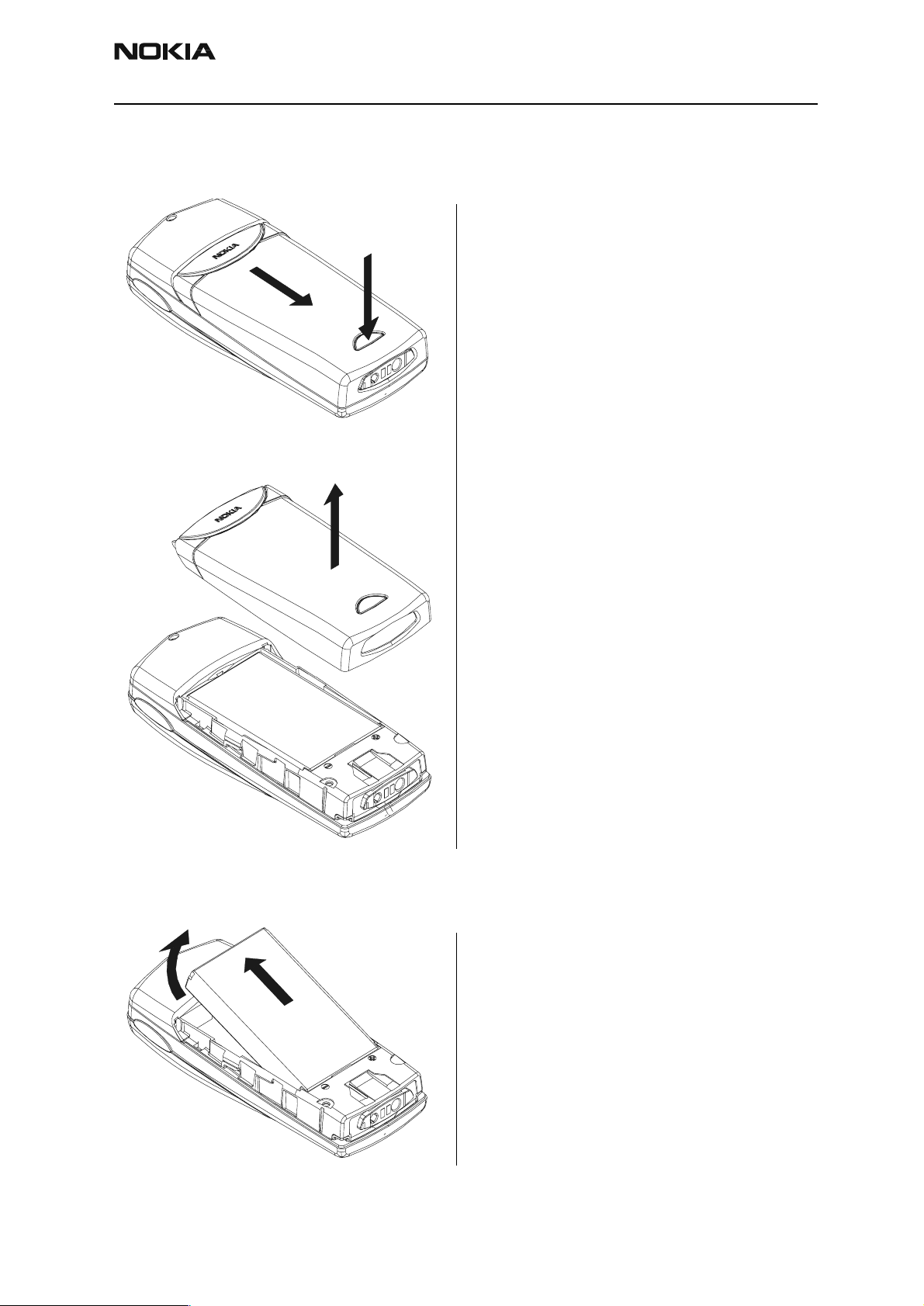
Disassembling the NSB-8 Transceiver
2
3
1
Remove Battery cover.
1
Remove Battery.
2
Issue 1 01/02 ãNokia Corporation Page 3
Page 4
NSB-8
Assembly & Disassembly Instructions PAMS Technical Documentation
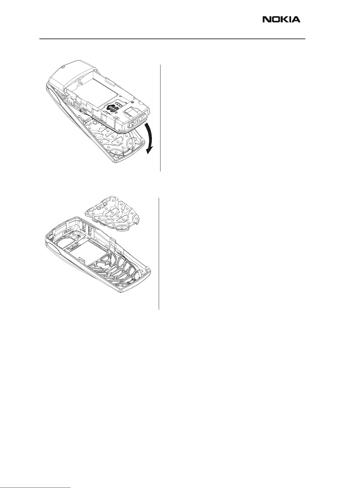
Remove A-cover.
When a new
A-cover is set
remove the inner
protective layer.
Remove Keypad
(only if it is necessary to
replace keypad).
In assembly place A-cov er
pins (4 pieces) in respective
holes in the keypad.
Page 4 ãNokia Corporation Issue 1 01/02
Page 5
NSB-8
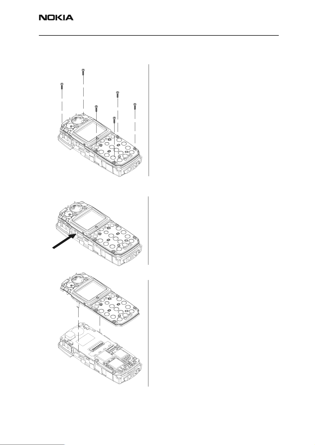
4.
PAMS Technical Documentation Assembly & Disassembly Instructions
Remove the 6 screws.
3.
1.
Drive size is torx plus 6.
2.
5.
6.
Note! Screws contain thread
locking compound. Used screws
must be scrapped and not used
again.
Remove UI module.
1. Use plastic tweezers or similar
tool to gently press the UI module
locking snap.
1
2
2. Carefully lift up the UI module.
UI handling precautions!
Do not damage the following
items when handling the UI
module:
1. Speaker spring contacts.
2. LCD driver.
3. LCD contact pads.
4. UI PWB contact pads.
5. UI frame metal coating.
Issue 1 01/02 ãNokia Corporation Page 5
Page 6

NSB-8
1.
Assembly & Disassembly Instructions PAMS Technical Documentation
2.
3.
4.
5.
UI handling precautions!
1. Speaker spring contacts.
2. LCD driver.
3. LCD contact pads.
4. UI PWB contact pads.
5. UI frame metal coating.
Remove speaker
(only if it is necessary to
replace speaker).
Speaker can be lifted up
using a straight-bladed
screwdriver as shown in
the picture.
Note! Do not touch
speaker springs or
membrane.
Page 6 ãNokia Corporation Issue 1 01/02
Page 7

NSB-8
PAMS Technical Documentation Assembly & Disassembly Instructions
Remove System Module
1.
2.
System Module handling
precautions!
Do not touch the following
spring contacts when
handling the module:
1. LCD connector.
2. Board to board connector.
Remove System connector
Note! Do not damage the
spring contacts in the
System connector.
Issue 1 01/02 ãNokia Corporation Page 7
Page 8

NSB-8
Assembly & Disassembly Instructions PAMS Technical Documentation
Remove SIM cover
(only if it is necessary to replace
SIM cover).
1
1. Slightly lift the front edge
of the SIM cover to unlocked
position
2. and slide it backwards.
2
4
3
5
3. Turn the SIM cover to
upright position.
4. Squeeze the SIM cover
slightly from the side to
release the side fixings one
at the time.
5. Pull SIM cover out of B cover.
Page 8 ãNokia Corporation Issue 1 01/02
Page 9

NSB-8
3
PAMS Technical Documentation Assembly & Disassembly Instructions
Assembling the NSB-8 Transceiver
1. Insert SIM cover into B-cover.
2. Squeeze the SIM cover from the
side and insert into the appropriate
slots in the B-cover.
2
3. Tilt SIM cover down.
4. Slide forward.
4
Issue 1 01/02 ãNokia Corporation Page 9
Page 10

NSB-8
Assembly & Disassembly Instructions PAMS Technical Documentation
1. Insert System Connector.
D
E
2. Insert System Module.
3. Obtain UI Module
Use caution handling the following:
A. Speaker spring contacts
B. LCD driver
C. LCD contact pads
D. PWB contact pads
E. Frame metal coating
Page 10 ãNokia Corporation Issue 1 01/02
Page 11

NSB-8
PAMS Technical Documentation Assembly & Disassembly Instructions
1. Insert UI Module into phone.
Locking
Snap
Fasten screws in the order as shown in
the picture.
Drive size is torx plus 6.
Tightening torque is 17Ncm @
800 - 1200 rpm.
Note: Screws contain threadlocking
compound. Screws without this
compound or used screws should not be
fastened.
Issue 1 01/02 ãNokia Corporation Page 11
Page 12

NSB-8
Assembly & Disassembly Instructions PAMS Technical Documentation
Insert Keymat into A-cover.
Attach A-cover to phone.
Page 12 ãNokia Corporation Issue 1 01/02
Page 13

NSB-8
PAMS Technical Documentation Assembly & Disassembly Instructions
Insert battery.
Snap
Attach battery cover.
Slide cover on till the snap locks it in
place.
Issue 1 01/02 ãNokia Corporation Page 13
Page 14

NSB-8
Assembly & Disassembly Instructions PAMS Technical Documentation
This page intentionally left blank.
Page 14 ãNokia Corporation Issue 1 01/02
 Loading...