

Page 1

Nokia Customer Care
Service Manual
RM-322; RM-323 (Nokia 6301)
Mobile Terminal
Part No: 9205161 (Issue 1)
COMPANY CONFIDENTIAL
Copyright © 2007 Nokia. All rights reserved.
Page 2

Amendment Record Sheet
Amendment Record Sheet
Amendment No Date Inserted By Comments
Issue 1 11/2007 Y Liu
RM-322; RM-323
Page ii COMPANY CONFIDENTIAL Issue 1
Copyright © 2007 Nokia. All rights reserved.
Page 3

RM-322; RM-323
Copyright
Copyright
Copyright © 2007 Nokia. All rights reserved.
Reproduction, transfer, distribution or storage of part or all of the contents in this document in any form
without the prior written permission of Nokia is prohibited.
Nokia, Nokia Connecting People, and Nokia X and Y are trademarks or registered trademarks of Nokia
Corporation. Other product and company names mentioned herein may be trademarks or tradenames of
their respective owners.
Nokia operates a policy of continuous development. Nokia reserves the right to make changes and
improvements to any of the products described in this document without prior notice.
Under no circumstances shall Nokia be responsible for any loss of data or income or any special, incidental,
consequential or indirect damages howsoever caused.
The contents of this document are provided "as is". Except as required by applicable law, no warranties of
any kind, either express or implied, including, but not limited to, the implied warranties of merchantability
and fitness for a particular purpose, are made in relation to the accuracy, reliability or contents of this
document. Nokia reserves the right to revise this document or withdraw it at any time without prior notice.
The availability of particular products may vary by region.
IMPORTANT
This document is intended for use by qualified service personnel only.
Issue 1 COMPANY CONFIDENTIAL Page iii
Copyright © 2007 Nokia. All rights reserved.
Page 4

RM-322; RM-323
Warnings and cautions
Warnings and cautions
Warnings
• IF THE DEVICE CAN BE INSTALLED IN A VEHICLE, CARE MUST BE TAKEN ON INSTALLATION IN VEHICLES FITTED
WITH ELECTRONIC ENGINE MANAGEMENT SYSTEMS AND ANTI-SKID BRAKING SYSTEMS. UNDER CERTAIN FAULT
CONDITIONS, EMITTED RF ENERGY CAN AFFECT THEIR OPERATION. IF NECESSARY, CONSULT THE VEHICLE DEALER/
MANUFACTURER TO DETERMINE THE IMMUNITY OF VEHICLE ELECTRONIC SYSTEMS TO RF ENERGY.
• THE PRODUCT MUST NOT BE OPERATED IN AREAS LIKELY TO CONTAIN POTENTIALLY EXPLOSIVE ATMOSPHERES,
FOR EXAMPLE, PETROL STATIONS (SERVICE STATIONS), BLASTING AREAS ETC.
• OPERATION OF ANY RADIO TRANSMITTING EQUIPMENT, INCLUDING CELLULAR TELEPHONES, MAY INTERFERE
WITH THE FUNCTIONALITY OF INADEQUATELY PROTECTED MEDICAL DEVICES. CONSULT A PHYSICIAN OR THE
MANUFACTURER OF THE MEDICAL DEVICE IF YOU HAVE ANY QUESTIONS. OTHER ELECTRONIC EQUIPMENT MAY
ALSO BE SUBJECT TO INTERFERENCE.
• BEFORE MAKING ANY TEST CONNECTIONS, MAKE SURE YOU HAVE SWITCHED OFF ALL EQUIPMENT.
Cautions
• Servicing and alignment must be undertaken by qualified personnel only.
• Ensure all work is carried out at an anti-static workstation and that an anti-static wrist strap is worn.
• Ensure solder, wire, or foreign matter does not enter the telephone as damage may result.
• Use only approved components as specified in the parts list.
• Ensure all components, modules, screws and insulators are correctly re-fitted after servicing and
alignment.
• Ensure all cables and wires are repositioned correctly.
• During testing never activate the GSM transmitter without a proper antenna load, otherwise the GSM PA
may be damaged.
Page iv COMPANY CONFIDENTIAL Issue 1
Copyright © 2007 Nokia. All rights reserved.
Page 5

RM-322; RM-323
For your safety
For your safety
QUALIFIED SERVICE
Only qualified personnel may install or repair phone equipment.
ACCESSORIES AND BATTERIES
Use only approved accessories and batteries. Do not connect incompatible products.
CONNECTING TO OTHER DEVICES
When connecting to any other device, read its user’s guide for detailed safety instructions. Do not connect
incompatible products.
Issue 1 COMPANY CONFIDENTIAL Page v
Copyright © 2007 Nokia. All rights reserved.
Page 6

RM-322; RM-323
Care and maintenance
Care and maintenance
This product is of superior design and craftsmanship and should be treated with care. The suggestions below
will help you to fulfil any warranty obligations and to enjoy this product for many years.
• Keep the phone and all its parts and accessories out of the reach of small children.
• Keep the phone dry. Precipitation, humidity and all types of liquids or moisture can contain minerals that
will corrode electronic circuits.
• Do not use or store the phone in dusty, dirty areas. Its moving parts can be damaged.
• Do not store the phone in hot areas. High temperatures can shorten the life of electronic devices, damage
batteries, and warp or melt certain plastics.
• Do not store the phone in cold areas. When it warms up (to its normal temperature), moisture can form
inside, which may damage electronic circuit boards.
• Do not drop, knock or shake the phone. Rough handling can break internal circuit boards.
• Do not use harsh chemicals, cleaning solvents, or strong detergents to clean the phone.
• Do not paint the phone. Paint can clog the moving parts and prevent proper operation.
• Use only the supplied or an approved replacement antenna. Unauthorised antennas, modifications or
attachments could damage the phone and may violate regulations governing radio devices.
All of the above suggestions apply equally to the product, battery, charger or any accessory.
Page vi COMPANY CONFIDENTIAL Issue 1
Copyright © 2007 Nokia. All rights reserved.
Page 7

RM-322; RM-323
ESD protection
ESD protection
Nokia requires that service points have sufficient ESD protection (against static electricity) when servicing
the phone.
Any product of which the covers are removed must be handled with ESD protection. The SIM card can be
replaced without ESD protection if the product is otherwise ready for use.
To replace the covers ESD protection must be applied.
All electronic parts of the product are susceptible to ESD. Resistors, too, can be damaged by static electricity
discharge.
All ESD sensitive parts must be packed in metallized protective bags during shipping and handling outside
any ESD Protected Area (EPA).
Every repair action involving opening the product or handling the product components must be done under
ESD protection.
ESD protected spare part packages MUST NOT be opened/closed out of an ESD Protected Area.
For more information and local requirements about ESD protection and ESD Protected Area, contact your local
Nokia After Market Services representative.
Issue 1 COMPANY CONFIDENTIAL Page vii
Copyright © 2007 Nokia. All rights reserved.
Page 8

RM-322; RM-323
Battery information
Battery information
Note: A new battery's full performance is achieved only after two or three complete charge and
discharge cycles!
The battery can be charged and discharged hundreds of times but it will eventually wear out. When the
operating time (talk-time and standby time) is noticeably shorter than normal, it is time to buy a new battery.
Use only batteries approved by the phone manufacturer and recharge the battery only with the chargers
approved by the manufacturer. Unplug the charger when not in use. Do not leave the battery connected to
a charger for longer than a week, since overcharging may shorten its lifetime. If left unused a fully charged
battery will discharge itself over time.
Temperature extremes can affect the ability of your battery to charge.
For good operation times with Ni-Cd/NiMh batteries, discharge the battery from time to time by leaving the
product switched on until it turns itself off (or by using the battery discharge facility of any approved accessory
available for the product). Do not attempt to discharge the battery by any other means.
Use the battery only for its intended purpose.
Never use any charger or battery which is damaged.
Do not short-circuit the battery. Accidental short-circuiting can occur when a metallic object (coin, clip or
pen) causes direct connection of the + and - terminals of the battery (metal strips on the battery) for example
when you carry a spare battery in your pocket or purse. Short-circuiting the terminals may damage the battery
or the connecting object.
Leaving the battery in hot or cold places, such as in a closed car in summer or winter conditions, will reduce
the capacity and lifetime of the battery. Always try to keep the battery between 15°C and 25°C (59°F and 77°
F). A phone with a hot or cold battery may temporarily not work, even when the battery is fully charged.
Batteries' performance is particularly limited in temperatures well below freezing.
Do not dispose of batteries in a fire!
Dispose of batteries according to local regulations (e.g. recycling). Do not dispose as household waste.
Page viii COMPANY CONFIDENTIAL Issue 1
Copyright © 2007 Nokia. All rights reserved.
Page 9

RM-322; RM-323
Company Policy
Company Policy
Our policy is of continuous development; details of all technical modifications will be included with service
bulletins.
While every endeavour has been made to ensure the accuracy of this document, some errors may exist. If
any errors are found by the reader, NOKIA MOBILE PHONES Business Group should be notified in writing/email.
Please state:
• Title of the Document + Issue Number/Date of publication
• Latest Amendment Number (if applicable)
• Page(s) and/or Figure(s) in error
Please send to:
NOKIA CORPORATION
Nokia Mobile Phones Business Group
Nokia Customer Care
PO Box 86
FIN-24101 SALO
Finland
E-mail: Service.Manuals@nokia.com
Issue 1 COMPANY CONFIDENTIAL Page ix
Copyright © 2007 Nokia. All rights reserved.
Page 10

RM-322; RM-323
Company Policy
(This page left intentionally blank.)
Page x COMPANY CONFIDENTIAL Issue 1
Copyright © 2007 Nokia. All rights reserved.
Page 11

RM-322; RM-323
Nokia 6301 Service Manual Structure
Nokia 6301 Service Manual Structure
1 General information
2 Service Tools and Service Concepts
3 BB Troubleshooting and Manual Tuning Guide
4 RF Troubleshooting and Manual Tuning Guide
5 System module
Glossary
Issue 1 COMPANY CONFIDENTIAL Page xi
Copyright © 2007 Nokia. All rights reserved.
Page 12

RM-322; RM-323
Nokia 6301 Service Manual Structure
(This page left intentionally blank.)
Page xii COMPANY CONFIDENTIAL Issue 1
Copyright © 2007 Nokia. All rights reserved.
Page 13

Nokia Customer Care
1 — General information
Issue 1 COMPANY CONFIDENTIAL Page 1 –1
Copyright © 2007 Nokia. All rights reserved.
Page 14

RM-322; RM-323
General information
(This page left intentionally blank.)
Page 1 –2 COMPANY CONFIDENTIAL Issue 1
Copyright © 2007 Nokia. All rights reserved.
Page 15

RM-322; RM-323
General information
Table of Contents
Product selection....................................................................................................................................................1–5
Phone features .......................................................................................................................................................1–5
Hardware features .................................................................................................................................................1–6
Software and User interface features ..................................................................................................................1–6
Accessories..............................................................................................................................................................1–8
List of Tables
Table 1 Audio..........................................................................................................................................................1–8
Table 2 Battery and chargers ................................................................................................................................1–8
Table 3 Car accessories ..........................................................................................................................................1–8
Table 4 Data ............................................................................................................................................................1–9
Table 5 Imaging......................................................................................................................................................1–9
List of Figures
Figure 1 The product picture of RM-322/323 ......................................................................................................1–5
Issue 1 COMPANY CONFIDENTIAL Page 1 –3
Copyright © 2007 Nokia. All rights reserved.
Page 16

RM-322; RM-323
General information
(This page left intentionally blank.)
Page 1 –4 COMPANY CONFIDENTIAL Issue 1
Copyright © 2007 Nokia. All rights reserved.
Page 17
RM-322; RM-323
General information
Product selection
The RM-322/323 is (max 2W) GSM triband hand portable phone, supporting GSM 850/1800/1900 (RM-323)
and 900/1800/1900 (RM-322) bands, respectively. The RM-322/323 also supports EGPRS and GPRS (Packed
data). Moreover, The RM-322/323 supports WLAN 802.11 b/g 2.4 Ghz for UMA (Unlicensed Mobile Access), with
automatic switching between WLAN and cellular networks. It is class B&C terminals, supporting EGPRS
multislot class 10 (4Rx + 1Tx and 3Rx + 2Tx) and GPRS multislot class 10 (4+1, 3+2).
The RM-322/323 is MMS (Multimedia Messaging Services) version 1.2 enabled phone with a QVGA 240x320
pixel, active TFT 16.7 million colour display. It also has an integrated 2 Mpix digital camera with a 8 x digtal
zoom.
The RM-322/323 has a 3GPP video player/recorder, FM stereo radio and a music player, and it supports
Bluetooth 2.0 + EDR standard as well as microSD card.
The XHTML/WAP browser in RM-322/323 is compatible with the version 2.0 specifications and it supports
HTTP/TCP/IP stack.
In addition the RM-322/323 is Java-enabled phone (JavaTM 2 Platform, Micro Edition, for embedded devices).
It supports MIDP Java 2.0 with additionally APIs.
The supported user interface is S40, that is, RM-322/323 software is based on the ISA platform.
Figure 1 The product picture of RM-322/323
Phone features
General features
• Demo mode (phone demo without SIM card)
Issue 1 COMPANY CONFIDENTIAL Page 1 –5
Copyright © 2007 Nokia. All rights reserved.
Page 18
RM-322; RM-323
General information
Hardware features
Display and keypad features
• Main display: Active TFT QVGA display supporting up to 16,7 million colors (320 x 240 pixels, 2 inches active
area)
• Power switch
• Side volume keys
Hardware characteristics
• Monoblock phone
• 2-Mpix camera with 8 x digital zoom
• Hotswap µSD memory card slot (under the battery cover)
• Stereo FM radio and music player
• Integrated handsfree speaker
• Internal vibra
• Bluetooth
• 2.0 mm DC charger plug interface
• Mini-USB connector
• 2.5mm Nokia AV connector
• WLAN 802.11 b/g
Software and User interface features
Software features
• ISA OS 8.0s Platform
•
Nokia Series 40 User interface (UI): JavaTM MIDP 2.0
UI features
Imaging • 2.0-megapixel camera with 8x digital zoom (1600 x 1200 pixel
resolution)
• Full-screen viewfinder
• PictBridge printing via USB cable
Multimedia • MP3 player supporting formats including MP3, Midi, AAC, AAC+, enhanced
AAC+, WMA
• FM stereo radio, Visual Radio and music player
• 3GPP video player/recorder
• MP3 ringing tones, True tones and MIDI tones, with support of 64
polyphony
Memory functions • Combo memory with 64 MB flash and 32 MB RAM – about 30 MB user
memory (for gallery and applications, contacts, notes, calendar entries)
• Hotswap microSD memory card slot supporting up to 2GB microSD
memory cards (available as enhancements)
Page 1 –6 COMPANY CONFIDENTIAL Issue 1
Copyright © 2007 Nokia. All rights reserved.
Page 19
RM-322; RM-323
General information
Messaging • Simplified messaging with recently used contacts log and groups
• Email: Access your work and private email accounts; supports SMTP,
POP3, and IMAP4 protocols. Support for attachments (Java version)
• Audio messaging service (AMS): Record your own voice message and send
to compatible devices
• MMS OMA 1.2: Combine image, video, text, and voice clips and send as an
MMS to a compatible phone or PC; use MMS to tell your story with a multislide presentation. The MMS OMA 1.2 specification allows you to send/
receive messages up to 300 kB in size.
• Text messaging: Supports concatenated SMS, picture messaging, SMS
distribution list
• Predictive text input: Support for all major languages in Europe and AsiaPacific
• Instant Messaging (IM)
Applications • Java™ MIDP 2.0 with over-the-air download
• Pre-installed Java™-based applications and games
• SIM Application Toolkit
• Wireless Presenter
Connectivity • WLAN 802.11 b/g 2.4 Ghz for UMA, with automatic switching between
WLAN and cellular networks
• Nokia PC Suite with USB and Bluetooth connectivity
• Bluetooth wireless connectivity (SIM access, headset, and handsfree
profiles) incl. stereo support for headsets
• Nokia AV connector interface with USB
• FOTA (Flashing over-the-air)
• Local/remote SyncML data synchronization
Browsing • Integrated XHTML browser
• Smart content download - OMA DRM 2.0
Data transfer • EDGE (EGPRS): Class 10, download up to 236.8 kbps
• GPRS: Class 10, download up to 53.6 kbps
Note: Actual achieved speeds may vary depending on network support
• GPRS/EDGE/HSCSD/CSD for browsing and as data modem
• Downlink Advanced Receiver Performance (DARP)
Voice features • Push To Talk: Select the person or group you want to talk to and press
the Push To Talk key to communicate
• Enhanced voice dialling with SIND: Speaker-independent name dialling
for easy call handling
• Integrated handsfree speaker with a new high quality speaker for better
audio experience (stereo widening effects when attaching the headset)
• Voice commands
• Voice recorder
Issue 1 COMPANY CONFIDENTIAL Page 1 –7
Copyright © 2007 Nokia. All rights reserved.
Page 20
RM-322; RM-323
General information
Digital services • User Interface (UI) themes including e.g. animated wallpapers,
screensavers, color schemes, ringing tones
• Ringing tones: Video, MP3 ringing tones, True Tones and MIDI ringing,
alert, and gaming tones with support of 64 polyphony
• OTA download possibility for: Themes, True Tones, MP3 ringing tones,
MIDI ringing tones, screensavers, wallpapers, 3GPP streaming, images
and videos, Series 40 Java games and applications
Personal information
management (PIM)
• Organizer with alarm clock, calendar, to-do list, notes, calculator,
countdown timer, and stopwatch
• Manage your time and information with the enhanced calendar that can
be synchronized, for example, with Microsoft and Lotus PIM application
calendars by using the Nokia PC Suite
Call management • Speed dialling
• Logs: Keeps lists of your dialled, received, and missed calls
• Automatic answer (works with headset or car kit only)
• Call waiting, call hold, call divert, call timer
Accessories
Table 1 Audio
Type Name
AD-42W Wireless audio gateway
HS-40 Mono headset
HS-16, HS-42,
HS-47
HS-24W,
HS-26W,HS-57
W
Stereo headsets
Wireless stereo headsets
Table 2 Battery and chargers
Type Name
Note: This phone is charged through the smaller Nokia standard interface (2.0 mm plug). The 3.5 mm
standard charger can be used together with the CA-44 charger adapter.
AC-3/AC-5 Compact charger
AC-4 Travel charger
BL-4C Battery 860 mAh Li-Ion
CA-44 Charger adapter (from 3.5 mm -> 2 mm)
Table 3 Car accessories
Type Name
CK-1W Wireless car kit
Page 1 –8 COMPANY CONFIDENTIAL Issue 1
Copyright © 2007 Nokia. All rights reserved.
Page 21
RM-322; RM-323
General information
Type Name
CK-7W Basic universal car kit
CK-20W Car Installation Kit
CR-39 Universal holder
DC-4 Mobile charger
HF-35W Wireless Car Handsfree
N616 Car phone
Type Name
DKE-2 Mini USB connectivity cable
MU-22 1 GB µSD card
MU-26 128 MB µSD card
Table 4 Data
MU-27 256 MB µSD card
MU-28 512 MB µSD card
MU-37 2 GB µSD card
Table 5 Imaging
Type Name
PT-6 Remote camera
Issue 1 COMPANY CONFIDENTIAL Page 1 –9
Copyright © 2007 Nokia. All rights reserved.
Page 22

RM-322; RM-323
General information
(This page left intentionally blank.)
Page 1 –10 COMPANY CONFIDENTIAL Issue 1
Copyright © 2007 Nokia. All rights reserved.
Page 23

Nokia Customer Care
2 — Service Tools and Service
Concepts
Issue 1 COMPANY CONFIDENTIAL Page 2 –1
Copyright © 2007 Nokia. All rights reserved.
Page 24

RM-322; RM-323
Service Tools and Service Concepts
(This page left intentionally blank.)
Page 2 –2 COMPANY CONFIDENTIAL Issue 1
Copyright © 2007 Nokia. All rights reserved.
Page 25

RM-322; RM-323
Service Tools and Service Concepts
Table of Contents
Service tools............................................................................................................................................................2–5
Product specific tools........................................................................................................................................2–5
FS-47..............................................................................................................................................................2–5
MJ-156 ...........................................................................................................................................................2–5
RJ-148 ............................................................................................................................................................2–5
SA-123 ...........................................................................................................................................................2–6
General tools......................................................................................................................................................2–6
CU-4................................................................................................................................................................2–7
FLS-4S ............................................................................................................................................................2–8
FLS-5 ..............................................................................................................................................................2–8
FPS-10............................................................................................................................................................2–8
JBT-9 ..............................................................................................................................................................2–9
PK-1................................................................................................................................................................2–9
PKD-1 .............................................................................................................................................................2–9
RJ-209 ...........................................................................................................................................................2–9
RJ-93 ..............................................................................................................................................................2–9
SB-7............................................................................................................................................................. 2–10
SPS-1........................................................................................................................................................... 2–10
SRT-6........................................................................................................................................................... 2–10
SS-45........................................................................................................................................................... 2–10
SS-46........................................................................................................................................................... 2–11
SS-62........................................................................................................................................................... 2–11
ST-40........................................................................................................................................................... 2–11
ST-64........................................................................................................................................................... 2–11
SX-4............................................................................................................................................................. 2–11
Cables............................................................................................................................................................... 2–12
CA-31D ........................................................................................................................................................ 2–12
CA-35S......................................................................................................................................................... 2–12
DAU-9S........................................................................................................................................................ 2–12
DKE-2........................................................................................................................................................... 2–13
PCS-1........................................................................................................................................................... 2–13
XCS-4........................................................................................................................................................... 2–13
XRE-2........................................................................................................................................................... 2–13
XRS-6........................................................................................................................................................... 2–14
Service concepts .................................................................................................................................................. 2–14
POS (Point of Sale) flash concept .................................................................................................................. 2–14
Flash concept with FPS-10............................................................................................................................. 2–15
CU-4 flash concept with FPS-10..................................................................................................................... 2–16
Module jig service concept............................................................................................................................ 2–17
RF testing concept with RF coupler .............................................................................................................. 2–18
Service concept for RF testing and RF/BB tuning........................................................................................ 2–19
List of Figures
Figure 2 POS flash concept ................................................................................................................................. 2–14
Figure 3 Basic flash concept with FPS-10.......................................................................................................... 2–15
Figure 4 CU-4 flash concept with FPS-10........................................................................................................... 2–16
Figure 5 Module jig service concept .................................................................................................................. 2–17
Figure 6 RF testing concept with RF coupler .................................................................................................... 2–18
Figure 7 Service concept for RF testing and RF/BB tuning .............................................................................. 2–19
Issue 1 COMPANY CONFIDENTIAL Page 2 –3
Copyright © 2007 Nokia. All rights reserved.
Page 26

RM-322; RM-323
Service Tools and Service Concepts
(This page left intentionally blank.)
Page 2 –4 COMPANY CONFIDENTIAL Issue 1
Copyright © 2007 Nokia. All rights reserved.
Page 27
RM-322; RM-323
Service Tools and Service Concepts
Service tools
Product specific tools
The table below gives a short overview of service tools that can be used for testing, error analysis and repair
of product RM-322; RM-323, refer to various concepts.
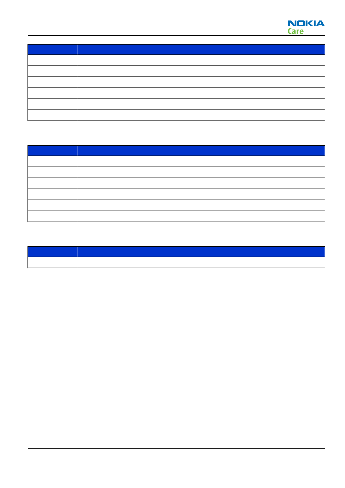
FS-47 Flash adapter For flashing (also dead phones) with SS-64. RF testing and tuning, and
EM calibration on ATO level with SS-62 (mechanical locking concept),
CU-4 supported.
MJ-156 Module jig MJ-156 is meant for troubleshooting, testing, tuning and flashing on
the engine level (CU-4 supported).
The jig includes an RF interface for GSM and Bluetooth.
The following table shows the attenuation values for galvanic RF
connetion:
•
Band Tuning
channel
Attenuation RX Attenuation
TX
GSM850 190 0.1 0.1
GSM900 37 0.1 0.1
GSM1800 700 0.15 0.15
GSM1900 661 0.15 0.15
WLAN 2437 MHz 0.2 0.2
RJ-148 Soldering jig RJ-148 is a soldering jig used for soldering and as a rework jig for the
engine module.
Issue 1 COMPANY CONFIDENTIAL Page 2 –5
Copyright © 2007 Nokia. All rights reserved.
Page 28
RM-322; RM-323
Service Tools and Service Concepts
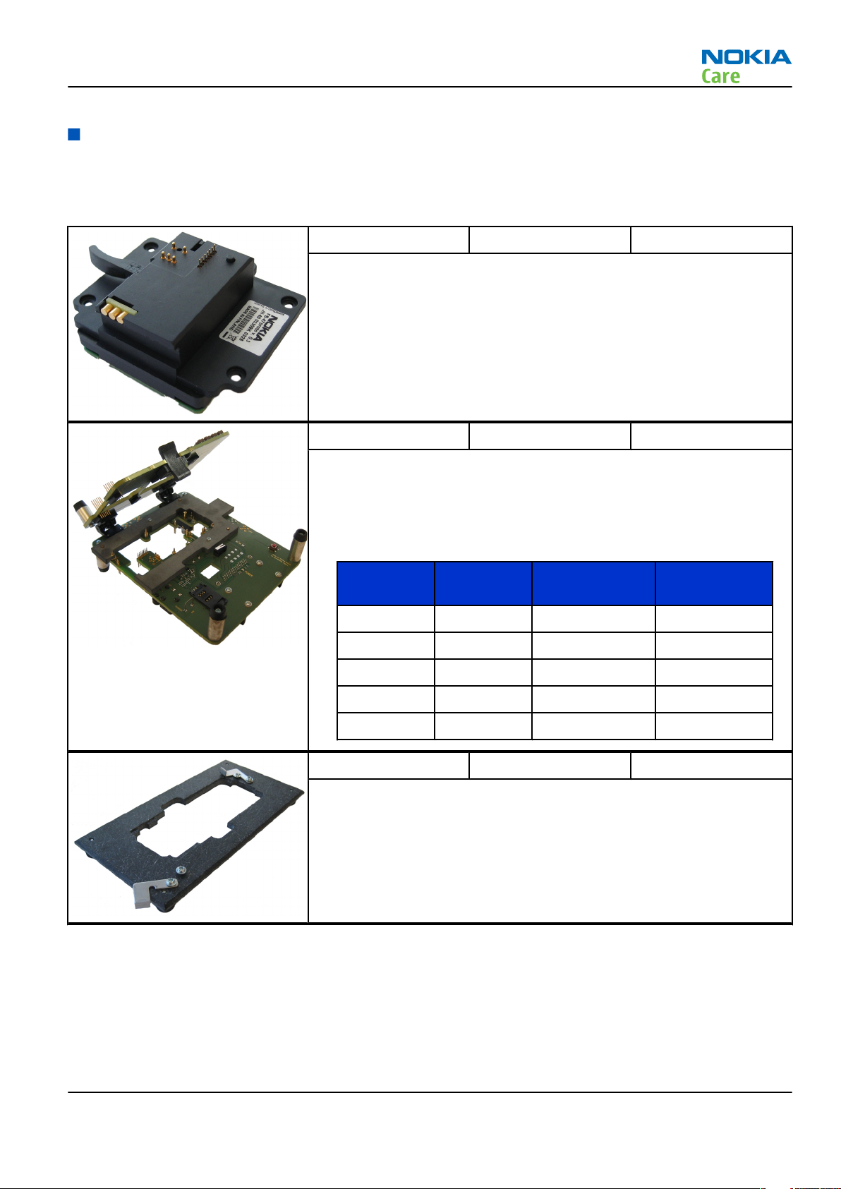
SA-123 RF coupler SA-123 is an RF coupler for GSM RF testing. It is used together with the
product-specific flash adapter.
The following table shows attenuations from the antenna pads of the
mobile terminal to the SMA connectors of SA-123:
• RM-322
Band Channel Tx-att. (dB) Rx-att. (dB)
EGSM 900 975 5.6 6
38 5.2 7
124 5.2 7
GSM 1800 512 7.3 10
698 8.2 10
885 8.1 10
GSM 1900 512 8.6 9
661 8.7 7
810 9.1 7
Tx-attenuation tolerance is +/-0.5 dB
Rx-attenuation tolerance is +/-1.0dB
• RM-323
Band Channel Tx-att. (dB) Rx-att. (dB)
GSM 850 128 8.1 9
190 7.4 9
251 7.7 10
GSM 1800 512 8.6 7
698 8.7 8
885 7.5 6
GSM 1900 512 6.7 8
661 6.1 8
810 6.8 8
Tx-attenuation tolerance is +/-0.5 dB
Rx-attenuation tolerance is +/-1.0dB
General tools
The table below gives a short overview of service tools that can be used for testing, error analysis and repair
of product RM-322; RM-323, refer to various concepts.
Page 2 –6 COMPANY CONFIDENTIAL Issue 1
Copyright © 2007 Nokia. All rights reserved.
Page 29
RM-322; RM-323
Service Tools and Service Concepts
CU-4 Control unit CU-4 is a general service tool used with a module jig and/or a flash
adapter. It requires an external 12 V power supply.
The unit has the following features:
• software controlled via USB
• EM calibration function
• Forwards FBUS/Flashbus traffic to/from terminal
• Forwards USB traffic to/from terminal
• software controlled BSI values
• regulated VBATT voltage
• 2 x USB2.0 connector (Hub)
• FBUS and USB connections supported
When using CU-4, note the special order of connecting cables and
other service equipment:
Instructions
1 Connect a service tool (jig, flash adapter) to CU-4.
2 Connect CU-4 to your PC with a USB cable.
3 Connect supply voltage (12 V)
4 Connect an FBUS cable (if necessary).
5 Start Phoenix service software.
Note: Phoenix enables CU-4 regulators via USB when it is
started.
Reconnecting the power supply requires a Phoenix restart.
Issue 1 COMPANY CONFIDENTIAL Page 2 –7
Copyright © 2007 Nokia. All rights reserved.
Page 30
RM-322; RM-323
Service Tools and Service Concepts
FLS-4S Flash device FLS-4S is a dongle and flash device incorporated into one package,
developed specifically for POS use.
FLS-5 Flash device FLS-5 is a dongle and flash device incorporated into one package,
developed specifically for POS use.
Note: FLS-5 can be used as an alternative to PKD-1.
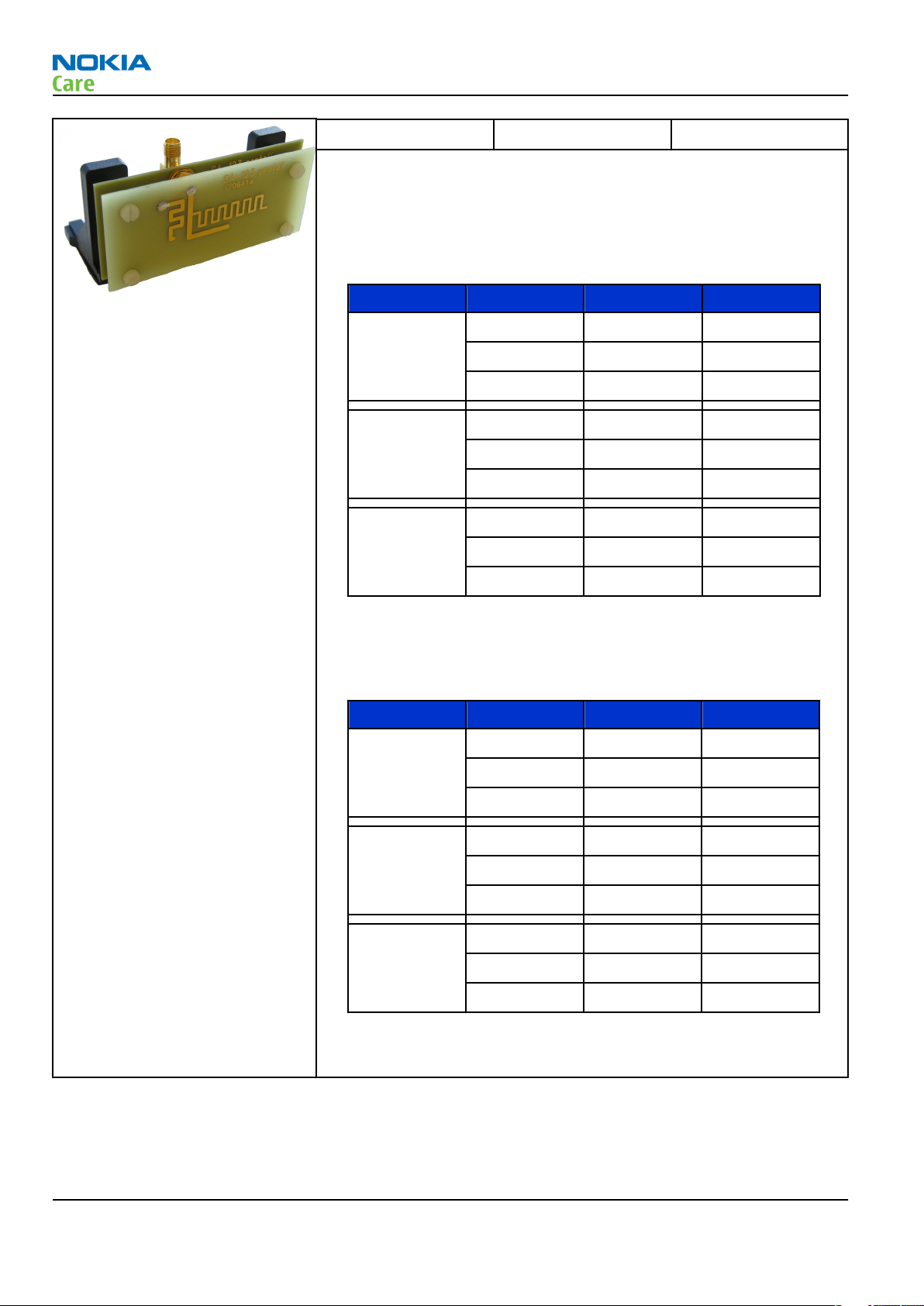
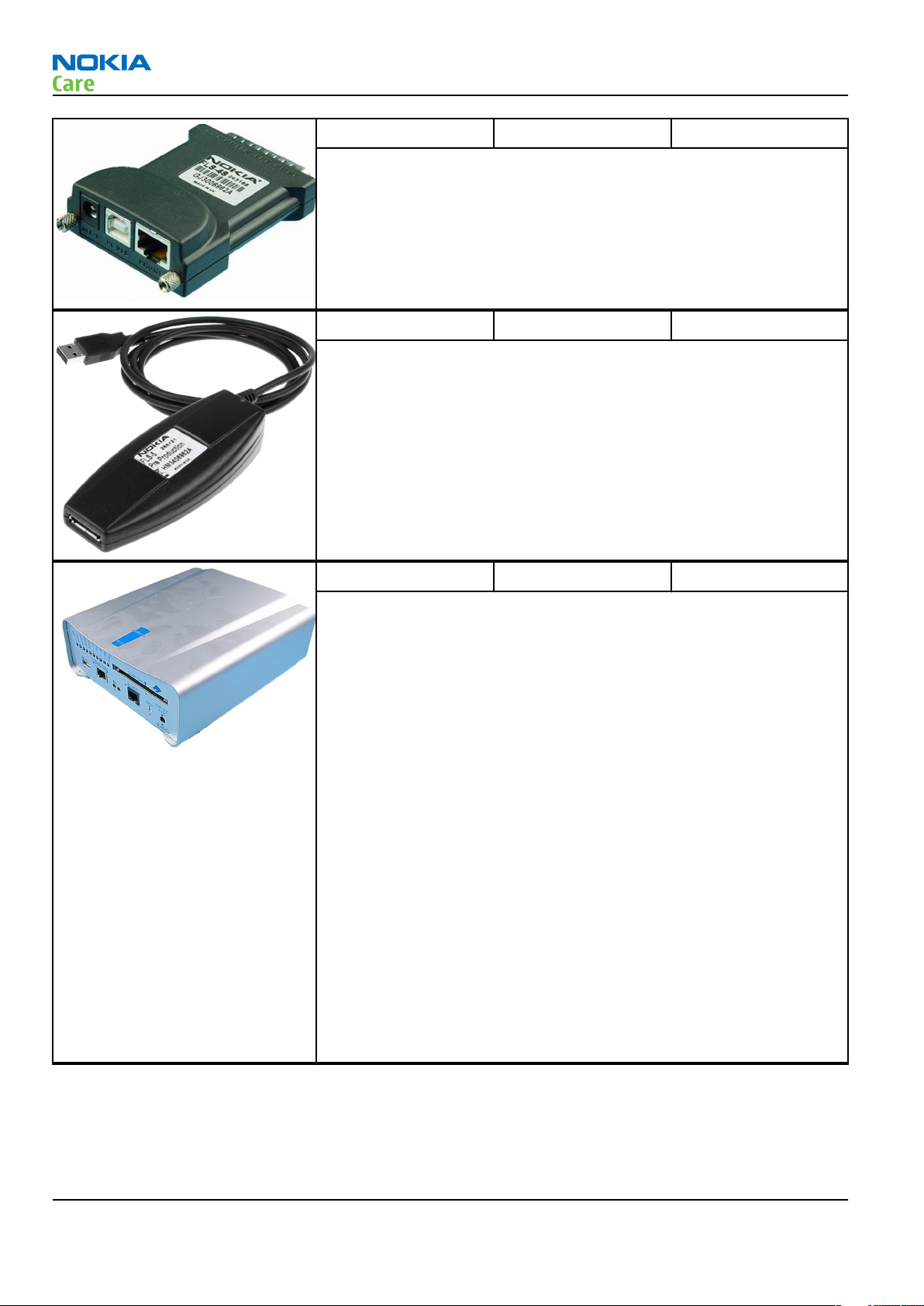
FPS-10 Flash prommer FPS-10 interfaces with:
• PC
• Control unit
• Flash adapter
• Smart card
FPS-10 flash prommer features:
• Flash functionality for BB5 and DCT-4 terminals
• Smart Card reader for SX-2 or SX-4
• USB traffic forwarding
• USB to FBUS/Flashbus conversion
• LAN to FBUS/Flashbus and USB conversion
• Vusb output switchable by PC command
FPS-10 sales package includes:
• FPS-10 prommer
• Power Supply with 5 country specific cords
• USB cable
Note: FPS-21 is substitute FPS-10 if FPS-10 has not been set
up.
Page 2 –8 COMPANY CONFIDENTIAL Issue 1
Copyright © 2007 Nokia. All rights reserved.
Page 31

RM-322; RM-323
Service Tools and Service Concepts
JBT-9 Bluetooth test and
interface box (sales
package)
The JBT-9 test box is a generic service device used to perform
Bluetooth bit error rate (BER) testing, and establishing cordless FBUS
connection via Bluetooth. An ACP-8x charger is needed for BER testing
and an AXS-4 cable in case of cordless interface usage testing .
Sales package includes:
• JBT-9 test box
• Installation and warranty information
PK-1 Software protection
key
PK-1 is a hardware protection key with a USB interface. It has the same
functionality as the PKD-1 series dongle.
PK-1 is meant for use with a PC that does not have a series interface.
To use this USB dongle for security service functions please register
the dongle in the same way as the PKD-1 series dongle.
PKD-1 SW security device
SW security device is a piece of hardware enabling the use of the
service software when connected to the parallel (LPT) port of the PC.
Without the device, it is not possible to use the service software.
Printer or any such device can be connected to the PC through the
device if needed.
RJ-209 Rework jig RJ-209 is used as a rework jig for the WLAN 4.0 module
This stencil takes the WLAN 4.0 module for spreading soldering paste
onto the component. This must be used together with the ST-64
rework stencil.
RJ-93 Rework jig RJ-93 is used as a rework jig for the engine module.
This stencil takes the front end module (FEM) or power amplifier (PA)
module for spreading the soldering paste to the component. Must be
used together with the ST-40 stencil.
Issue 1 COMPANY CONFIDENTIAL Page 2 –9
Copyright © 2007 Nokia. All rights reserved.
Page 32

RM-322; RM-323
Service Tools and Service Concepts
SB-7 WLAN test box WLAN test requires defined position for the device.
SPS-1 Soldering Paste
Spreader
The SPS-1 allows spreading of solder to the LGA components pads over
the rework stencils.
SRT-6 Opening tool SRT-6 is used to open phone covers.
SS-45 Front camera
removal tool
The front camera removal tool SS-45 is used to remove/attach the
front camera module from/to the socket.
Page 2 –10 COMPANY CONFIDENTIAL Issue 1
Copyright © 2007 Nokia. All rights reserved.
Page 33

RM-322; RM-323
Service Tools and Service Concepts
SS-46 Interface adapter SS-46 acts as an interface adapter between the flash adapter and
FPS-10.
SS-62 Generic flash adapter
base for BB5
• generic base for flash adapters and couplers
• SS-62 equipped with a clip interlock system
• provides standardised interface towards Control Unit
• provides RF connection using galvanic connector or coupler
• multiplexing between USB and FBUS media, controlled by VUSB
ST-40 Rework stencil ST-40 is a rework stencil and used with RJ-93.
ST-64 Rework stencil ST-64 is the stencil used during rework of the WLAN 4.0 module. It
must be used together with the RJ-209 rework jig.
SX-4 Smart card SX-4 is a BB5 security device used to protect critical features in tuning
and testing.
SX-4 is also needed together with FPS-10 when DCT-4 phones are
flashed.
Issue 1 COMPANY CONFIDENTIAL Page 2 –11
Copyright © 2007 Nokia. All rights reserved.
Page 34

RM-322; RM-323
Service Tools and Service Concepts
Cables
The table below gives a short overview of service tools that can be used for testing, error analysis and repair
of product RM-322; RM-323, refer to various concepts.
CA-31D USB cable The CA-31D USB cable is used to connect FPS-10 or FPS-11 to a PC. It is
included in the FPS-10 and FPS-11 sales packages.
CA-35S Power cable CA-35S is a power cable for connecting, for example, the FPS-10 flash
prommer to the Point-Of-Sales (POS) flash adapter.
DAU-9S MBUS cable The MBUS cable DAU-9S has a modular connector and is used, for
example, between the PC's serial port and module jigs, flash adapters
or docking station adapters.
Note: Docking station adapters valid for DCT4 products.
Page 2 –12 COMPANY CONFIDENTIAL Issue 1
Copyright © 2007 Nokia. All rights reserved.
Page 35

RM-322; RM-323
Service Tools and Service Concepts
DKE-2 Mini-USB cable USB to mini-USB connector cable.
PCS-1 Power cable The PCS-1 power cable (DC) is used with a docking station, a module
jig or a control unit to supply a controlled voltage.
XCS-4 Modular cable XCS-4 is a shielded (one specially shielded conductor) modular cable
for flashing and service purposes.
XRE-2 Bluetooth cable The bluetooth cable connects the bluetooth connector of the module
jig to the bluetooth test box JBT-9.
Issue 1 COMPANY CONFIDENTIAL Page 2 –13
Copyright © 2007 Nokia. All rights reserved.
Page 36

Service concepts
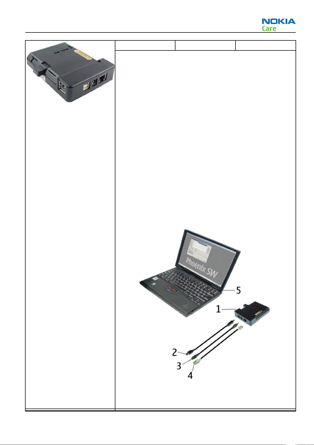
POS (Point of Sale) flash concept
RM-322; RM-323
Service Tools and Service Concepts
XRS-6 RF cable The RF cable is used to connect, for example, a module repair jig to
the RF measurement equipment.
SMA to N-Connector approximately 610 mm.
Attenuation for:
• GSM850/900: 0.3+-0.1 dB
• GSM1800/1900: 0.5+-0.1 dB
• WLAN: 0.6+-0.1dB
Figure 2 POS flash concept
Type Description
Product specific devices
BL-4C Battery
Other devices
ACP-8 Power adapter
FLS-4S or
FLS-5
Page 2 –14 COMPANY CONFIDENTIAL Issue 1
POS flash dongle
Copyright © 2007 Nokia. All rights reserved.
Page 37

RM-322; RM-323
Service Tools and Service Concepts
Type Description
PC with Phoenix service software
Cables
DKE-2 USB connectivity cable
Flash concept with FPS-10
Figure 3 Basic flash concept with FPS-10
Type Description
Product specific devices
FS-47 Flash adapter
Other devices
FPS-10 Flash prommer box
PKD-1/PK-1 SW security device
SS-46 Interface adapter
PC with Phoenix service software
Cables
XCS-4 Modular cable
CA-35S Power cable
Issue 1 COMPANY CONFIDENTIAL Page 2 –15
Copyright © 2007 Nokia. All rights reserved.
Page 38

Type Description
USB cable
CU-4 flash concept with FPS-10
RM-322; RM-323
Service Tools and Service Concepts
Figure 4 CU-4 flash concept with FPS-10
Type Description
Product specific devices
FS-47 Flash adapter
Other devices
CU-4 Control unit
FPS-10 Flash prommer box
PKD-1/PK-1 SW security device
SS-62 Flash adapter base
SX-4 Smart card
PC with Phoenix service software
Cables
PCS-1 Power cable
XCS-4 Modular cable
Standard USB cable
Page 2 –16 COMPANY CONFIDENTIAL Issue 1
Copyright © 2007 Nokia. All rights reserved.
Page 39

RM-322; RM-323
Service Tools and Service Concepts
Type Description
USB cable
Module jig service concept
Figure 5 Module jig service concept
Type Description
Phone specific devices
MJ-156 Module jig
Other devices
CU-4 Control unit
FPS-10 Flash prommer box
PK-1 SW security device
SX-4 Smart card
PC with VPOS and Phoenix service software
Measurement equipment
Cables
PCS-1 DC power cable
XCS-4 Modular cable
Issue 1 COMPANY CONFIDENTIAL Page 2 –17
Copyright © 2007 Nokia. All rights reserved.
Page 40

Type Description
XRF-1 RF cable
USB cable
GPIB control cable
RF testing concept with RF coupler
RM-322; RM-323
Service Tools and Service Concepts
Figure 6 RF testing concept with RF coupler
Type Description
Product specific devices
FS-47 Flash adapter
SA-123 RF coupler
Other devices
CU-4 Control unit
SX-4 Smart card
FPS-10 Flash prommer box
PKD-1/PK-1 SW security device
SS-62 Flash adapter base
Measurement equipment
PC with Phoenix service software
Page 2 –18 COMPANY CONFIDENTIAL Issue 1
Copyright © 2007 Nokia. All rights reserved.
Page 41

RM-322; RM-323
Service Tools and Service Concepts
Type Description
Cables
PCS-1 Power cable
XCS-4 Modular cable
XRS-6 RF cable
GPIB control cable
USB cable
Service concept for RF testing and RF/BB tuning
Figure 7 Service concept for RF testing and RF/BB tuning
Type Description
Product specific devices
MJ-156 Module jig
Other devices
CU-4 Control unit
PK-1 SW security device
SX-4 Smart card
Measurement equipment
Issue 1 COMPANY CONFIDENTIAL Page 2 –19
Copyright © 2007 Nokia. All rights reserved.
Page 42

Type Description
Smart card reader
PC with Phoenix service software
Cables
DAU-9S MBUS cable
PCS-1 DC power cable
XRS-6 RF cable
GPIB control cable
USB cable
RM-322; RM-323
Service Tools and Service Concepts
Page 2 –20 COMPANY CONFIDENTIAL Issue 1
Copyright © 2007 Nokia. All rights reserved.
Page 43

Nokia Customer Care
3 — BB Troubleshooting and
Manual Tuning Guide
Issue 1 COMPANY CONFIDENTIAL Page 3 –1
Copyright © 2007 Nokia. All rights reserved.
Page 44

RM-322; RM-323
BB Troubleshooting and Manual Tuning Guide
(This page left intentionally blank.)
Page 3 –2 COMPANY CONFIDENTIAL Issue 1
Copyright © 2007 Nokia. All rights reserved.
Page 45

RM-322; RM-323
BB Troubleshooting and Manual Tuning Guide
Table of Contents
Baseband troubleshooting overview...................................................................................................................3–5
Power and charging troubleshooting..................................................................................................................3–6
General power checking troubleshooting ......................................................................................................3–6
Battery current measuring fault troubleshooting .........................................................................................3–6
Charging troubleshooting ................................................................................................................................3–8
Clocking troubleshooting .................................................................................................................................3–9
Interface troubleshooting .................................................................................................................................. 3–10
Camera failure ................................................................................................................................................ 3–10
Introduction to camera troubleshooting ............................................................................................... 3–10
Taking and evaluating test pictures........................................................................................................ 3–10
Camera hardware troubleshooting......................................................................................................... 3–11
Camera viewfinder troubleshooting....................................................................................................... 3–12
Camera: Bad image quality troubleshooting ......................................................................................... 3–13
COMBO memory troubleshooting ................................................................................................................. 3–14
Flash programming fault troubleshooting.................................................................................................. 3–15
MicroSD card troubleshooting....................................................................................................................... 3–16
User interface troubleshooting.......................................................................................................................... 3–19
Display module troubleshooting.................................................................................................................. 3–19
General instructions for display troubleshooting.................................................................................. 3–19
Display troubleshooting ........................................................................................................................... 3–21
Backlight troubleshooting............................................................................................................................. 3–22
Reminder LED troubleshooting..................................................................................................................... 3–23
LED driver troubleshooting ........................................................................................................................... 3–23
Audio troubleshooting........................................................................................................................................ 3–25
Introduction to acoustics troubleshooting ................................................................................................. 3–25
Audio troubleshooting test instructions...................................................................................................... 3–25
Earpiece troubleshooting.............................................................................................................................. 3–28
Internal earpiece troubleshooting ............................................................................................................... 3–29
External headset earpiece troubleshooting ................................................................................................ 3–30
IHF troubleshooting....................................................................................................................................... 3–31
IHF troubleshooting....................................................................................................................................... 3–32
Microphone troubleshooting ........................................................................................................................ 3–33
Internal microphone troubleshooting......................................................................................................... 3–34
External headset microphone troubleshooting.......................................................................................... 3–35
Connections troubleshooting............................................................................................................................. 3–36
USB interface troubleshooting...................................................................................................................... 3–36
Baseband manual tuning guide......................................................................................................................... 3–37
Certificate restoring for BB5 products.......................................................................................................... 3–37
Energy management calibration.................................................................................................................. 3–42
List of Tables
Table 6 Display module troubleshooting cases................................................................................................ 3–19
Table 7 Pixel defects ........................................................................................................................................... 3–20
Table 8 Calibration value limits ......................................................................................................................... 3–42
List of Figures
Figure 8 Flashing pic 1. Take single trig measurement for the rise of the BSI signal.................................. 3–16
Figure 9 Flashing pic 2. Take single trig measurement for the rise of the BSI signal.................................. 3–16
Issue 1 COMPANY CONFIDENTIAL Page 3 –3
Copyright © 2007 Nokia. All rights reserved.
Page 46

RM-322; RM-323
BB Troubleshooting and Manual Tuning Guide
Figure 10 Location of the microSD card reader in RM-322/323...................................................................... 3–17
Figure 11 SD card initialization from pin J3206 ............................................................................................... 3–18
Figure 12 Single-ended output waveform of the Ext_in_HP_out measurement when earpiece is
connected. ................................................................................................................................................. 3–26
Figure 13 Differential output waveform of the Ext_in_IHF_out out loop measurement when speaker is
connected. ................................................................................................................................................. 3–27
Figure 14 Single-ended output waveform of the HP_in_Ext_out loop when microphone is connected....
3–27
Page 3 –4 COMPANY CONFIDENTIAL Issue 1
Copyright © 2007 Nokia. All rights reserved.
Page 47

RM-322; RM-323
BB Troubleshooting and Manual Tuning Guide
Baseband troubleshooting overview
This section is intended to be a guide for localising and repairing electrical faults.
The table below tells you what troubleshooting to go to.
Problem Troubleshooting
Abnormal current consumption 1 General power checking (page 3–6)
2 Battery current measuring fault (page 3–6)
Flashing does not work or the problem is not clearly
defined
Charging does not work Charging (page 3–8)
Display does not work Display fault (page )
Backlights do not work 1 Backlight (page 3–22)
Reminder LEDs do not work Reminder LED (page 3–23)
USB does not work USB (page 3–36)
Audio (mic, earpiece, IHF) does not work 1 Audio (page 3–25)
Camera does not work 1 Camera baseband hardware (page 3–11)
Bluetooth does not work Bluetooth (BT) (page )
FM radio does not work FM radio (page )
1 Flashing (page 3–15)
2 Clocking (page 3–9)
3 Combo memory (page 3–14)
2 LED driver (page 3–8)
2 Acoustics (page 3–25)
2 Camera viewfinder (page 3–12)
3 Bad image quality (page 3–13)
MicroSD card does not work MicroSD card (page )
Issue 1 COMPANY CONFIDENTIAL Page 3 –5
Copyright © 2007 Nokia. All rights reserved.
Page 48

Power and charging troubleshooting
General power checking troubleshooting
Troubleshooting flow
RM-322; RM-323
BB Troubleshooting and Manual Tuning Guide
Page 3 –6 COMPANY CONFIDENTIAL Issue 1
Copyright © 2007 Nokia. All rights reserved.
Page 49

RM-322; RM-323
BB Troubleshooting and Manual Tuning Guide
Battery current measuring fault troubleshooting
Troubleshooting flow
Issue 1 COMPANY CONFIDENTIAL Page 3 –7
Copyright © 2007 Nokia. All rights reserved.
Page 50

Charging troubleshooting
Troubleshooting flow
RM-322; RM-323
BB Troubleshooting and Manual Tuning Guide
Page 3 –8 COMPANY CONFIDENTIAL Issue 1
Copyright © 2007 Nokia. All rights reserved.
Page 51

RM-322; RM-323
BB Troubleshooting and Manual Tuning Guide
Clocking troubleshooting
Troubleshooting flow
Issue 1 COMPANY CONFIDENTIAL Page 3 –9
Copyright © 2007 Nokia. All rights reserved.
Page 52

RM-322; RM-323
BB Troubleshooting and Manual Tuning Guide
Interface troubleshooting
Camera failure
Introduction to camera troubleshooting
Bad conditions often cause bad pictures. Therefore, the camera operation has to be checked in constant
conditions or by using a second, known-to-be-good Nokia device as reference. Image quality is hard to
measure quantitatively, and the difference between a good and a bad picture can be small. Some training
or experience may be needed to detect what is actually wrong.
When checking for possible errors in camera functionality, knowing what error is suspected significantly
helps the testing by narrowing down the amount of test cases. The following types of image quality problems
are common:
• Dust (black spots)
• Lack of sharpness
• Bit errors
Taking and evaluating test pictures
When
• Avoid bright fluorescent light, 50/60Hz electrical network or high artificial illumination levels
• If the phone is hot, let it rest for a while before taking the picture
• Make sure the optical system is clean
• Use highest possible resolution
• Make sure the light is suffiecient (bright office lightning)
• Do not take the picture towards light source
• Be as still as possible when taking the picture
• Distance should be at least 40cm, 1-2m is recommended
When
• The center of the picture is sharper than the edges
• The image may be blurred, though it does not show in the viewfinder
• Analyse the picture from your PC monitor, full colour setting is recommended
• If possible, compare with a picture of the same motive taken with a similar Nokia device
taking
a test picture, remember the following:
evaluating
a test picture, remember the following:
Page 3 –10 COMPANY CONFIDENTIAL Issue 1
Copyright © 2007 Nokia. All rights reserved.
Page 53

RM-322; RM-323
BB Troubleshooting and Manual Tuning Guide
Camera hardware troubleshooting
Troubleshooting flow
Issue 1 COMPANY CONFIDENTIAL Page 3 –11
Copyright © 2007 Nokia. All rights reserved.
Page 54

Camera viewfinder troubleshooting
Troubleshooting flow
RM-322; RM-323
BB Troubleshooting and Manual Tuning Guide
Page 3 –12 COMPANY CONFIDENTIAL Issue 1
Copyright © 2007 Nokia. All rights reserved.
Page 55

RM-322; RM-323
BB Troubleshooting and Manual Tuning Guide
Camera: Bad image quality troubleshooting
Troubleshooting flow
Issue 1 COMPANY CONFIDENTIAL Page 3 –13
Copyright © 2007 Nokia. All rights reserved.
Page 56

COMBO memory troubleshooting
Troubleshooting flow
RM-322; RM-323
BB Troubleshooting and Manual Tuning Guide
Page 3 –14 COMPANY CONFIDENTIAL Issue 1
Copyright © 2007 Nokia. All rights reserved.
Page 57

RM-322; RM-323
BB Troubleshooting and Manual Tuning Guide
Flash programming fault troubleshooting
Part 1
Issue 1 COMPANY CONFIDENTIAL Page 3 –15
Copyright © 2007 Nokia. All rights reserved.
Page 58

Part 2
RM-322; RM-323
BB Troubleshooting and Manual Tuning Guide
Figure 8 Flashing pic 1. Take single trig measurement for the rise of the BSI signal.
Figure 9 Flashing pic 2. Take single trig measurement for the rise of the BSI signal.
MicroSD card troubleshooting
Context
In the RM-322/323 the microSD card reader is located under the battery cover.
Page 3 –16 COMPANY CONFIDENTIAL Issue 1
Copyright © 2007 Nokia. All rights reserved.
Page 59

RM-322; RM-323
BB Troubleshooting and Manual Tuning Guide
Figure 10 Location of the microSD card reader in RM-322/323
Issue 1 COMPANY CONFIDENTIAL Page 3 –17
Copyright © 2007 Nokia. All rights reserved.
Page 60

Troubleshooting flow
RM-322; RM-323
BB Troubleshooting and Manual Tuning Guide
Page 3 –18 COMPANY CONFIDENTIAL Issue 1
Copyright © 2007 Nokia. All rights reserved.
Page 61

RM-322; RM-323
BB Troubleshooting and Manual Tuning Guide
Take single trig measurement on the rising edge of the DAT signal.
Figure 11 SD card initialization from pin J3206
User interface troubleshooting
Display module troubleshooting
General instructions for display troubleshooting
Context
The RM-322/323 has three display modes:
•
Normal mode
•
Partial idle mode
•
Sleep mode
the phone is switched on. To verify if the phone display is sleeping, press a key.
The operating modes of the display can be controlled with the phone settings menu.
Display blank There is no image on the display. The display looks
Image on the display not correct Image on the display can be corrupted or a part of
: The display is in normal mode when the phone is in active use.
: The display is in partial idle mode when the power saver is on.
: The display has a sleep mode to conserve power. In this mode the display looks blank, but
Table 6 Display module troubleshooting cases
the same when the phone is on as it does when the
phone is off. The backlight can be on in some cases.
the image can be missing. If a part of the image is
missing, change the display module. If the image is
otherwise corrupted, follow the appropriate
troubleshooting diagram.
Backlight dim or not working at all Backlight LED components are inside the display
module. Backlight failure can also be in the
connector or in the backlight power source in the
main engine of the phone.
This means that in case the display is working
(image OK), the backlight is faulty.
Issue 1 COMPANY CONFIDENTIAL Page 3 –19
Copyright © 2007 Nokia. All rights reserved.
Page 62

RM-322; RM-323
BB Troubleshooting and Manual Tuning Guide
Visual defects (pixel) Pixel defects can be checked by controlling the
display with Phoenix. Use both colours, black and
white, on a full screen.
The display may have some random pixel defects
that are acceptable for this type of display. The
criteria when pixel defects are regarded as a display
failure, resulting in a replacement of the display, are
presented the following table.
Table 7 Pixel defects
Item White dot defect Black dot
defect
1 Defect counts R G B White Dot
Total
1 1 1 1
2 Combined
defect counts
Not allowed.
Two single dot defects that are within 5 mm of each other should be
interpreted as combined dot defect.
1 1
Total
Steps
1. Verify with a working display that the fault is not on the display module itself.
The display module cannot be repaired.
2. Check that the cellular engine is working normally.
i To check the functionality, connect the phone to a docking station.
ii Start
iii Read the phone information to check that also the application engine is functioning normally (you
3. Proceed to the display troubleshooting flowcharts.
Use the Display Test tool in
Phoenix
should be able to read the APE ID).
service software.
Phoenix
to find the detailed fault mode.
Page 3 –20 COMPANY CONFIDENTIAL Issue 1
Copyright © 2007 Nokia. All rights reserved.
Page 63

RM-322; RM-323
BB Troubleshooting and Manual Tuning Guide
Display troubleshooting
Troubleshooting flow
Issue 1 COMPANY CONFIDENTIAL Page 3 –21
Copyright © 2007 Nokia. All rights reserved.
Page 64

RM-322; RM-323
BB Troubleshooting and Manual Tuning Guide
Backlight troubleshooting
Context
The device has one LED driver that provides current for both the display and keyboard backlights. Brightness
can be adjusted manually, and it affects both the display and keypad. Keyboard backlights can be turned ON/
OFF separately but not without switching on the display lights.
Display and keyboard backlight troubleshooting
Page 3 –22 COMPANY CONFIDENTIAL Issue 1
Copyright © 2007 Nokia. All rights reserved.
Page 65

RM-322; RM-323
BB Troubleshooting and Manual Tuning Guide
Reminder LED troubleshooting
Troubleshooting flow
Issue 1 COMPANY CONFIDENTIAL Page 3 –23
Copyright © 2007 Nokia. All rights reserved.
Page 66

LED driver troubleshooting
LED driver troubleshooting
RM-322; RM-323
BB Troubleshooting and Manual Tuning Guide
Page 3 –24 COMPANY CONFIDENTIAL Issue 1
Copyright © 2007 Nokia. All rights reserved.
Page 67

RM-322; RM-323
BB Troubleshooting and Manual Tuning Guide
Audio troubleshooting
Introduction to acoustics troubleshooting
Note: Always make sure all openings are clean and all contact pads are intact and make contact. If
audio still does not work, please continue to the electronic audio troubleshooting (2nd diagram
where applicable).
Acoustics design ensures that the sound is detected correctly with a microphone and properly radiated to
the outside of the device by speaker(s). The acoustics of the phone includes three basic systems: earpiece,
Integrated Hands Free (IHF) and microphone.
The sound reproduced from the earpiece readiates through a single hole on the front cover (A-cover). The
sound reproduced from the IHF speaker radiates from a single sound hole located 3 cm below the power key.
The microphone is located at the hinge, next to the system connector.
For a correct functionality of the phone, all sound holes must be always open. When the phone is used, care
must be taken not to close any of those holes with a hand or fingers. The phone should be dry and clean,
and no objects must be located in such a way that they close any of the holes.
Audio troubleshooting test instructions
Differential internal earpiece outputs can be measured either with a single-ended or a differential probe.
When measuring with a single-ended probe each output is measured against the ground.
Internal handsfree output is measured using a current probe, if a special low-pass filter designed for
measuring a digital amplifier is not available. Note also that when using a current probe, the input signal
frequency must be set to 2kHz.
The input signal for each loop test can be single-ended.
Required equipment
The following equipment is needed for the tests:
• Oscilloscope
• Function generator (sine waveform)
• Current probe (Internal handsfree PWM output measurement)
• Phoenix service software
• Battery voltage 3.7V
Test procedure
Audio can be tested using the Phoenix audio routings option. Three different audio loop paths can be
activated:
• External microphone to Internal earpiece
• External microphone to Internal handsfree speaker
• Internal microphone to External earpiece
Each audio loop sets routing from the specified input to the specified output enabling a quick in-out test.
Loop path gains are fixed and they cannot be changed using Phoenix. Correct pins and signals for each test
are presented in the following table.
Phoenix audio loop tests and test results
The results presented in the table apply when no accessory is connected and battery voltage is set to 3.7V.
Earpiece, internal microphone and speaker are in place during measurement. Applying a headset accessory
during measurement causes a significant drop in measured quantities.
Issue 1 COMPANY CONFIDENTIAL Page 3 –25
Copyright © 2007 Nokia. All rights reserved.
Page 68

RM-322; RM-323
BB Troubleshooting and Manual Tuning Guide
The gain values presented in the table apply for a differential output vs. single-ended/differential input.
Loop test Input
External Mic to
External Earpiece
External Mic to
Internal Earpiece
External Mic to
Internal handsfree
Internal Mic to
External Earpiece
terminal
XMICP and
GND
XMICP and
GND
XMICP and
GND
B2100 (OUT/
GND)
Output
terminal
HSEAR R
and GND
HSEAR L and
GND
EarP and
GND
EarN and
GND
E2101 pad 8.5 920 2520 0 25mA
E2102 pad
HSEAR R
and GND
HSEAR L and
GND
Path
gain
[dB]
(fixed)
-2.9 1000 720 1.2 NA
-4.0 750 490 1.2 NA
22.7 100 1360 1.2 NA
Input
voltage
[mVp-p]
Differe
ntial
output
voltage
[mVp-
p]
Outp
ut DC
level
[V]
Output
current
(calc.)
[mA]
Measurement data
Figure 12 Single-ended output waveform of the Ext_in_HP_out measurement when earpiece is connected.
Page 3 –26 COMPANY CONFIDENTIAL Issue 1
Copyright © 2007 Nokia. All rights reserved.
Page 69

RM-322; RM-323
BB Troubleshooting and Manual Tuning Guide
Figure 13 Differential output waveform of the Ext_in_IHF_out out loop measurement when speaker is connected.
Figure 14 Single-ended output waveform of the HP_in_Ext_out loop when microphone is connected.
Issue 1 COMPANY CONFIDENTIAL Page 3 –27
Copyright © 2007 Nokia. All rights reserved.
Page 70

Earpiece troubleshooting
Troubleshooting flow
RM-322; RM-323
BB Troubleshooting and Manual Tuning Guide
Page 3 –28 COMPANY CONFIDENTIAL Issue 1
Copyright © 2007 Nokia. All rights reserved.
Page 71

RM-322; RM-323
BB Troubleshooting and Manual Tuning Guide
Internal earpiece troubleshooting
Troubleshooting flow
Issue 1 COMPANY CONFIDENTIAL Page 3 –29
Copyright © 2007 Nokia. All rights reserved.
Page 72

External headset earpiece troubleshooting
Troubleshooting flow
RM-322; RM-323
BB Troubleshooting and Manual Tuning Guide
Page 3 –30 COMPANY CONFIDENTIAL Issue 1
Copyright © 2007 Nokia. All rights reserved.
Page 73

RM-322; RM-323
BB Troubleshooting and Manual Tuning Guide
IHF troubleshooting
Troubleshooting flow
Issue 1 COMPANY CONFIDENTIAL Page 3 –31
Copyright © 2007 Nokia. All rights reserved.
Page 74

IHF troubleshooting
Troubleshooting flow
RM-322; RM-323
BB Troubleshooting and Manual Tuning Guide
Page 3 –32 COMPANY CONFIDENTIAL Issue 1
Copyright © 2007 Nokia. All rights reserved.
Page 75

RM-322; RM-323
BB Troubleshooting and Manual Tuning Guide
Microphone troubleshooting
Troubleshooting flow
Issue 1 COMPANY CONFIDENTIAL Page 3 –33
Copyright © 2007 Nokia. All rights reserved.
Page 76

Internal microphone troubleshooting
Troubleshooting flow
RM-322; RM-323
BB Troubleshooting and Manual Tuning Guide
Page 3 –34 COMPANY CONFIDENTIAL Issue 1
Copyright © 2007 Nokia. All rights reserved.
Page 77

RM-322; RM-323
BB Troubleshooting and Manual Tuning Guide
External headset microphone troubleshooting
Troubleshooting flow
Issue 1 COMPANY CONFIDENTIAL Page 3 –35
Copyright © 2007 Nokia. All rights reserved.
Page 78

Connections troubleshooting
USB interface troubleshooting
Troubleshooting flow
RM-322; RM-323
BB Troubleshooting and Manual Tuning Guide
Page 3 –36 COMPANY CONFIDENTIAL Issue 1
Copyright © 2007 Nokia. All rights reserved.
Page 79

RM-322; RM-323
BB Troubleshooting and Manual Tuning Guide
Baseband manual tuning guide
Certificate restoring for BB5 products
Context
This procedure is performed when the device certificate is corrupted for some reason.
All tunings (RF & Baseband, UI) must be done after performing the certificate restoring procedure.
The procedure for certificate restoring is the following:
• Flash the phone with the latest available software using FPS-8 or FPS-10.
• Create a request file.
• Send the file to Nokia by e-mail. Use the following addresses depending on your location:
• APAC: sydney.service@nokia.com
• CHINA: repair.ams@nokia.com
• E&A: salo.repair@nokia.com
• AMERICAS: fls1.usa@nokia.com
• When you receive a reply from Nokia, carry out certificate restoring.
• Tune the phone completely.
Note: SX-4 smart card is needed.
• If the phone resets after certificate restoring, reflash the phone again.
Required equipment and setup:
•
Phoenix
• The latest phone model specific
• PKD-1 dongle
• SX-4 smart card (Enables BB5 testing and tuning features)
• External smart card reader
• Activated FPS-8 flash prommer OR FPS-10 flash prommer
• Flash update package 03.18.004 or newer for FPS-8 or FPS-10 flash prommers
• CU-4 control unit
• USB cable from PC USB Port to CU-4 control unit
• Phone model specific adapter for CU-4 control unit
• PCS-1 cable to power CU-4 from external power supply
• XCS-4 modular cable between flash prommer and CU-4
service software v 2007.34.8.30060 or newer.
Phoenix
Note: The smart card reader is only needed when FPS-8 is used. FPS-10 has an integrated smart card
reader.
Note: CU-4 must be supplied with +12 V from an external power supply in all steps of certificate
restoring.
data package.
Steps
1. Program the phone software.
i Start
ii Update the phone MCU software to the latest available version.
Issue 1 COMPANY CONFIDENTIAL Page 3 –37
Phoenix
If the new flash is empty and the phone cannot communicate with
and login. Make sure the connection has been managed correctly for FPS-8 or FPS-10.
Copyright © 2007 Nokia. All rights reserved.
Phoenix
, reflash the phone.
Page 80

BB Troubleshooting and Manual Tuning Guide
iii Choose the product manually from File→Open Product , and click OK.
Wait for the phone type designator (e.g. “RM-1” ) to be displayed in the status bar.
iv Go to Flashing→SW Update and wait until
picture.
Phoenix
reads the product data as shown in the following
RM-322; RM-323
Product is automatically set according to the phone support module which was opened manually,
but the flash files cannot be found because the correct data cannot be read from the phone
automatically.
Code must be chosen manually, it determines the correct flash files to be used. Please choose the
correct product code (can be seen in the phone type label) from the dropdown list.
Flash Type must be set to Phone as Manufactured.
v To continue, click Start.
Progress bars and messages on the screen show actions during phone programming, please wait.
Page 3 –38 COMPANY CONFIDENTIAL Issue 1
Copyright © 2007 Nokia. All rights reserved.
Page 81

RM-322; RM-323
BB Troubleshooting and Manual Tuning Guide
Programming is completed when
The product type designator and MCU SW version are displayed in the status bar.
vi Close the
2. Create a
For this procedure, you must supply +12 V to CU-4 from an external power supply.
i To connect the phone with
ii Choose Tools→Certificate Restore .
iii To choose a location for the request file, click Browse.
SW Update
Request
window and then choose File→Close Product .
file.
Phoenix
Flashing Completed
, choose File→Scan Product .
message is displayed.
Issue 1 COMPANY CONFIDENTIAL Page 3 –39
Copyright © 2007 Nokia. All rights reserved.
Page 82

BB Troubleshooting and Manual Tuning Guide
iv Name the file so that you can easily identify it, and click Open.
The name of the file and its location are shown.
RM-322; RM-323
v To create the
vi When the file for certificate restore has been created, send it to Nokia as an e-mail attachment.
3. Restore certificate.
For this procedure, you must supply +12 V to CU-4 from an external power supply.
i Save the reply file sent by Nokia to your computer.
ii Start
iii Choose File→Scan Product .
Phoenix
Request
service software.
file, click Start.
Page 3 –40 COMPANY CONFIDENTIAL Issue 1
Copyright © 2007 Nokia. All rights reserved.
Page 83

RM-322; RM-323
BB Troubleshooting and Manual Tuning Guide
iv From the Tools menu, choose Certificate Restore and select Process a response file in the
pane.
v To choose the location where response file is saved, click Browse.
vi Click Open.
Action
The name of the file and the path where it is located are shown.
vii To write the file to phone, click Start.
Next actions
After a successful rewrite, you must retune the phone completely by using
Important: Perform all tunings: RF, BB, and UI.
Issue 1 COMPANY CONFIDENTIAL Page 3 –41
Copyright © 2007 Nokia. All rights reserved.
Phoenix
tuning functions.
Page 84

RM-322; RM-323
BB Troubleshooting and Manual Tuning Guide
Energy management calibration
Prerequisites
Energy Management (EM) calibration is performed to calibrate the setting (gain and offset) of AD converters
in several channels (that is, battery voltage, BSI, battery current) to get an accurate AD conversion result.
Hardware setup:
• An external power supply is needed.
• Supply 12V DC from an external power supply to CU-4 to power up the phone.
• The phone must be connected to a CU-4 control unit with a product-specific flash adapter.
Steps
1. Place the phone to the docking station adapter (CU-4 is connected to the adapter).
2. Start
3. Choose File→ Scan Product.
4. Choose Tuning→Energy Management Calibration.
5. To show the current values in the phone memory, click Read, and check that communication between
6. Check that the CU-4 used check box is checked.
7. Select the item(s) to be calibrated.
8. Click Calibrate.
Phoenix
the phone and CU-4 works.
Note: ADC calibration has to be performed before other item(s). However, if all calibrations are
selected at the same time, there is no need to perform the ADC calibration first.
The calibration of the selected item(s) is carried out automatically.
The candidates for the new calibration values are shown in the
calibration values seem to be acceptable (please refer to the following "Calibration value limits" table),
click Write to store the new calibration values to the phone permanent memory.
service software.
Calculated values
column. If the new
Table 8 Calibration value limits
Parameter Min. Max.
ADC Offset -20 20
ADC Gain 12000 14000
BSI Gain 1100 1300
VBAT Offset 2400 2650
VBAT Gain 19000 23000
VCHAR Gain N/A N/A
IBAT (ICal) Gain 7750 12250
9. Click Read, and confirm that the new calibration values are stored in the phone memory correctly. If the
values are not stored to the phone memory, click Write and/or repeat the procedure again.
10. To end the procedure, close the
Page 3 –42 COMPANY CONFIDENTIAL Issue 1
Energy Management Calibration
Copyright © 2007 Nokia. All rights reserved.
window.
Page 85

Nokia Customer Care
4 — RF Troubleshooting and
Manual Tuning Guide
Issue 1 COMPANY CONFIDENTIAL Page 4 –1
Copyright © 2007 Nokia. All rights reserved.
Page 86

RM-322; RM-323
RF Troubleshooting and Manual Tuning Guide
(This page left intentionally blank.)
Page 4 –2 COMPANY CONFIDENTIAL Issue 1
Copyright © 2007 Nokia. All rights reserved.
Page 87

RM-322; RM-323
RF Troubleshooting and Manual Tuning Guide
Table of Contents
Introduction to RF troubleshooting .....................................................................................................................4–5
RF key components ................................................................................................................................................4–6
Receiver troubleshooting ......................................................................................................................................4–6
Introduction to RX troubleshooting................................................................................................................4–6
General instructions for RX troubleshooting..................................................................................................4–7
Receiver (RX) troubleshooting .........................................................................................................................4–8
GSM Rx chain activation for manual measurements / GSM RSSI measurement....................................... 4–10
Transmitter troubleshooting ............................................................................................................................. 4–11
General instructions for TX troubleshooting............................................................................................... 4–11
Transceiver (TX) troubleshooting................................................................................................................. 4–14
Checking antenna functionality.................................................................................................................... 4–14
Synthesizer troubleshooting.............................................................................................................................. 4–17
RF tunings ............................................................................................................................................................ 4–18
Introduction to RF tunings............................................................................................................................ 4–18
Auto tuning for BB5.0 .................................................................................................................................... 4–18
System mode independent manual tunings .................................................................................................... 4–19
RF channel filter calibration.......................................................................................................................... 4–19
PA (power amplifier) detection .................................................................................................................... 4–20
GSM receiver tunings........................................................................................................................................... 4–20
Rx calibration (GSM) ....................................................................................................................................... 4–20
Rx band filter response compensation (GSM).............................................................................................. 4–23
GSM transmitter tunings..................................................................................................................................... 4–26
Tx IQ tuning (GSM).......................................................................................................................................... 4–26
Tx power level tuning (GSM) ......................................................................................................................... 4–28
Bluetooth and FM radio troubleshooting ......................................................................................................... 4–30
Introduction to Bluetooth and FM troubleshooting................................................................................... 4–30
Bluetooth and FM radio self tests................................................................................................................. 4–32
Bluetooth BER Test......................................................................................................................................... 4–33
BTHFMRDS2.0D Discrete ASIC Circuit Troubleshooting Flow....................................................................... 4–35
WLAN troubleshooting........................................................................................................................................ 4–37
WLAN functionality test using SB-7 and Phoenix........................................................................................ 4–37
WLAN layout and test points......................................................................................................................... 4–37
WLAN settings for Phoenix............................................................................................................................ 4–38
WLAN functional tests.................................................................................................................................... 4–40
WLAN failure troubleshooting ...................................................................................................................... 4–42
WLAN basic checks troubleshooting ............................................................................................................ 4–44
List of Tables
Table 9 Rf channel filter calibration tuning limits ........................................................................................... 4–19
Table 10 RF tuning limits in Rx calibration....................................................................................................... 4–22
List of Figures
Figure 15 RF key components, bottom side main board ...................................................................................4–6
Figure 16 RF Controls window ..............................................................................................................................4–8
Figure 17 RSSI Reading window........................................................................................................................ 4–11
Figure 18 RF Controls window ........................................................................................................................... 4–13
Figure 19 Location of the GSM and BT/WLAN antenna C-clips on the PWB ................................................... 4–15
Figure 20 GSM and BT/WLAN antenna contact pads on the antenna module .............................................. 4–16
Issue 1 COMPANY CONFIDENTIAL Page 4 –3
Copyright © 2007 Nokia. All rights reserved.
Page 88

RM-322; RM-323
RF Troubleshooting and Manual Tuning Guide
Figure 21 Antenna C-clips on the PWB .............................................................................................................. 4–16
Figure 22 Auto tuning concept with CMU200................................................................................................... 4–18
Figure 23 Rf channel filter calibration typical values ...................................................................................... 4–19
Figure 24 Test points for BTHFMRDS2.0D.......................................................................................................... 4–32
Page 4 –4 COMPANY CONFIDENTIAL Issue 1
Copyright © 2007 Nokia. All rights reserved.
Page 89

RM-322; RM-323
RF Troubleshooting and Manual Tuning Guide
Introduction to RF troubleshooting
On the following pages you will find a step-by-step troubleshooting procedure and reference measurements
at the relevant signal points. For functional descriptions, please refer to the System module section.
Notes on reference measurements
All measurements must be done using:
• spectrum analyser with a high-frequency high-impedance passive probe (LO-/reference frequencies and
RF power levels)
• oscilloscope with a 10:1 probe (DC-voltages and low frequency signals)
Important: All measurements with an RF coupler must be performed in an RF shielded environment,
or where there are no transmissions on the same frequencies. This may disturb sensitive receiver
measurements.
Repairing this phone - important
The RF section of the phone is built around one RF ASIC. Before changing the RF ASIC, please make sure that
supply voltages and serial communication coming from baseband to RF are OK.
Please note that the grounding of the FEM module is directly below the FEM module. Therefore, it is difficult
to check or change the module.
Most RF semiconductors are static discharge sensitive! ESD protection must be taken care of during repair
(ground straps and ESD soldering irons). The RF ASIC and FEM are moisture sensitive, so parts must be prebaked prior to soldering.
In addition to key components, there are lot of discrete components (resistors, inductors and capacitors)
which troubleshooting is done mainly by checking if the soldering of the component is done properly.
Capacitor can be checked for shorts and resistors for value by means of an ohmmeter, but be aware in-circuit
measurements should be evaluated carefully.
Keep in mind that all measured voltages or RF levels depicted in the service manual are rough figures.
Especially RF levels vary because of different measuring equipment or different grounding of the probe used.
When using an RF probe, use a pair of metallic tweezers to connect the probe ground to the PWB ground as
close to the measurement point as possible. If measurements are performed in a product specific module
jig, then “GND” pads should be used for the probe ground.
Supported bands
The following part of the service manual contains a description of all four GSM bands. It covers both variants,
RM-322 and RM-323. Both variants support three GSM bands as follows:
• RM-322: GSM900, GSM1800, GSM1900
• RM-323: GSM850, GSM1800, GSM1900
Make sure to investigate only the bands, which the phone is made for.
Issue 1 COMPANY CONFIDENTIAL Page 4 –5
Copyright © 2007 Nokia. All rights reserved.
Page 90

RF key components
RM-322; RM-323
RF Troubleshooting and Manual Tuning Guide
Figure 15 RF key components, bottom side main board
Receiver troubleshooting
Introduction to RX troubleshooting
Rx can be tested by making a phone call or in the local mode. For the local mode testing, use Phoenix service
software.
The main Rx troubleshooting measurement is RSSI measurement. This test measures the signal strength of
the received signal. I and Q branches can be measured separately.
Page 4 –6 COMPANY CONFIDENTIAL Issue 1
Copyright © 2007 Nokia. All rights reserved.
Page 91

RM-322; RM-323
RF Troubleshooting and Manual Tuning Guide
In GSM, the input signal can be either a real GSM signal or a CW signal that is 67.771kHz up from the carrier
frequency.
For service tool usage instructions, refer to section Service Tools and Service Concepts.
General instructions for RX troubleshooting
Steps
1. Connect a test jig to a computer with a DAU-9S cable or to a FPS-10 flash prommer with a modular cable
(XCS-4).
Make sure that you have a PKD-1 dongle connected to the computer's parallel port.
2. Connect CU-4 with 12 V supply. The DC supply voltage is set to 3.7 V by default (in Phoenix).
3. Connect an RF cable between the RF connector of the module test jig (MJ-156) and measurement
equipment or alternatively use a 50 Ω (at least 2 W) dummy load in the module test jig RF connector,
otherwise the RF part may be damaged.
Note: Make sure that all connections are made to the correct RF connector.
4. Set Rx on.
i Set the phone module to the test jig and start
ii Initialize connection to the phone. (With the FPS-10 prommer use FPS10_USB or FPS10_TCP drivers,
depending on connection type. When using DAU-9S select FBUS).
iii From the File menu, choose product: File -> Choose Product -> xx-x* (* = type designator of the
phone, eg. RM-322/323), or press Ctrl + R to scan product.
iv From the toolbar, set operating mode to “Local”.
5. EGSM850/900/1800/1900 troubleshooting
i From the Testing menu, activate the
RF Controls
Phoenix service software
window: Testing -> GSM -> RF Controls .
.
ii In the
• Select band.
• Set Active unit to “Rx” (Default ).
• Set Operation mode to “Burst” (Default).
• Set Rx/Tx channel (see table below).
• Apply a frequency (see table below) to the RF-connector.
Issue 1 COMPANY CONFIDENTIAL Page 4 –7
RF Controls
Note: Remember to compensate for cable attenuation, specific for MJ-156. You will find the values
in the Service tools section.
Apply a signal to the RF-connector (remember to compensate for cable attenuation). See values in
the table below.
window:
Copyright © 2007 Nokia. All rights reserved.
Page 92

RM-322; RM-323
RF Troubleshooting and Manual Tuning Guide
Band Channel (RX and
TX)
GSM850 190 881.66771 67.710 -90
GSM900 37 942.46771 67.710 -90
GSM1800 700 1842.86771 67.710 -90
GSM1900 661 1960.06771 67.710 -90
Input frequency
(MHz)
Offset (kHz) Power level
(dBm)
Figure 16 RF Controls window
Receiver (RX) troubleshooting
Context
Troubleshoot one band at a time. Start with the lowest band, and end with GSM1900.
Receiver troubleshooting
Apply a signal according to the table in General instructions for RX troubleshooting (page 4–7)
Page 4 –8 COMPANY CONFIDENTIAL Issue 1
Copyright © 2007 Nokia. All rights reserved.
Page 93

RM-322; RM-323
RF Troubleshooting and Manual Tuning Guide
Issue 1 COMPANY CONFIDENTIAL Page 4 –9
Copyright © 2007 Nokia. All rights reserved.
Page 94

RM-322; RM-323
RF Troubleshooting and Manual Tuning Guide
Page 4 –10 COMPANY CONFIDENTIAL Issue 1
Copyright © 2007 Nokia. All rights reserved.
Page 95

RM-322; RM-323
RF Troubleshooting and Manual Tuning Guide
GSM Rx chain activation for manual measurements / GSM RSSI measurement
Context
RSSI signal measurement is the main Rx troubleshooting measurement. The test measures the strength of
the received signal.
I and Q branches can be measured separately. In GSM, the input signal can be either a real GSM signal or a
CW (Continuous Wave) signal that is 67.771 kHz above the carrier frequency.
Steps
1. Start
2. Choose Testing→GSM→RSSI Reading .
3. Set the RF signal generator for a channel frequency +67.771 kHz in CW mode with a –80 dBm signal level.
4. In the
Phoenix
Alternatively set the cellular tester downlink channel to the appropriate channel. Make sure that the tester
is set to continuous mode, not to burst mode.
RSSI Reading
service software.
window, select the appropriate band and channel.
Figure 17
5. To start the measurement, activate GSM Rx chain, click Start.
RSSI Reading
window
Results
RSSI reading values of the selected band and channel are displayed. The RSSI level must be the same value
as that which is set at the signal generator (-80 dBm).
Transmitter troubleshooting
General instructions for TX troubleshooting
Context
• Tx troubleshooting requires Tx operation.
• Do not transmit on frequencies that are in use!
• Transmitter can be controlled in the local mode for diagnostic purposes.
• The most useful Phoenix tool for GSM transmitter testing is "RF Controls".
Issue 1 COMPANY CONFIDENTIAL Page 4 –11
Copyright © 2007 Nokia. All rights reserved.
Page 96

RM-322; RM-323
RF Troubleshooting and Manual Tuning Guide
• Tx IQ tuning and Tx power tuning can be also used in some cases.
• Remember that retuning is not a fix! Phones are tuned correctly in production.
The first set of steps instructs how to assemble the test setup. This setup is general for all Tx troubleshooting
tasks.
Alternative steps provide specific troubleshooting instructions for
Caution: Never activate the GSM transmitter without a proper antenna load. There should be always
50 Ω load connected to the RF connector (antenna, RF-measurement equipment or at least 2 W
dummy load), otherwise the GSM Power amplifier may be damaged.
Phoenix
service software.
Steps
1. Connect a test jig to a computer with a DAU-9S cable or to a FPS-10 flash prommer with a modular cable
(XCS-4).
Make sure that you have a PKD-1 dongle connected to the computer's parallel port.
2. Connect CU-4 with 12 V supply. The DC supply voltage is set to 3.7 V by default (in Phoenix).
3. Connect an RF cable between the RF connector of the module test jig (MJ-156) and measurement
equipment or alternatively use a 50 Ω (at least 2 W) dummy load in the module test jig RF connector,
otherwise GSM may be damaged.
Note: There are two antenna connectors in the module jig:
• one for GSM
• one for Bluetooth
Make sure that all connections are made to the correct RF connector.
Normally a spectrum analyser is used as measurement equipment.
Note: The maximum input power of a spectrum analyser is +30 dBm.
To prevent any damage, it is recommended to use 10 dB attenuator on the spectrum analyzer input.
4. Set Tx on.
i Set the phone module to the test jig and start
ii Initialize connection to the phone. (With the FPS-10 prommer use FPS10_USB or FPS10_TCP drivers,
depending on connection type. When using DAU-9S select FBUS driver).
iii From the File menu, choose product: File -> Choose Product -> xx-x* (* = type designator of the
phone, e.g. RM-322/323), or pressCtrl + R to scan product.
iv From the toolbar, set operating mode to “Local”.
5. GSM850/900/1800/1900 troubleshooting
i From the Testing menu, activate the
RF Controls
Phoenix service software
window: Testing -> GSM -> RF Controls .
.
ii In the
• Select band "GSM850", “GSM900” or “GSM1800” or “GSM1900”.
• Set Active unit to “Tx” (Default = “Rx”).
Page 4 –12 COMPANY CONFIDENTIAL Issue 1
RF Controls
window:
Copyright © 2007 Nokia. All rights reserved.
Page 97

RM-322; RM-323
RF Troubleshooting and Manual Tuning Guide
• Set Operation mode to “Burst” (Default).
• Set Tx data type to “All1” (Default).
• Set Rx/Tx channel (see table below)
• Set Edge to “Off” (Default).
• Set Tx PA mode to “High” (Default).
• Set power level (see table below)
Band Channel (RX and TX) TX power level
GSM850 190 5
GSM900 37 5
GSM1800 700 0
GSM1900 661 0
Figure 18 RF Controls window
Issue 1 COMPANY CONFIDENTIAL Page 4 –13
Copyright © 2007 Nokia. All rights reserved.
Page 98

Transceiver (TX) troubleshooting
Troubleshooting flow
RM-322; RM-323
RF Troubleshooting and Manual Tuning Guide
Page 4 –14 COMPANY CONFIDENTIAL Issue 1
Copyright © 2007 Nokia. All rights reserved.
Page 99

RM-322; RM-323
RF Troubleshooting and Manual Tuning Guide
Checking antenna functionality
GSM antenna
In the GSM antenna, there is one feed and two GND contacts.
Between GND1 and Feed, a DC short-circuit can be measured.
GND2 has no DC connection to the other contacts.
The antenna is functioning normally, if the contact pads hit the antenna C-clips on the PWB and the antenna
is visually intact.
BT/WLAN antenna
The BT/WLAN antenna is (as the GSM antenna) placed on the flex foil on the antenna module. It has one feed
and one short contact. The antenna is functioning normally, if the contact pads hit the antenna C-clips on
the PWB and the antenna is visually intact.
Figure 19 Location of the GSM and BT/WLAN antenna C-clips on the PWB
Issue 1 COMPANY CONFIDENTIAL Page 4 –15
Copyright © 2007 Nokia. All rights reserved.
Page 100

RM-322; RM-323
RF Troubleshooting and Manual Tuning Guide
Figure 20 GSM and BT/WLAN antenna contact pads on the antenna module
Antenna C-clips
When checking the antenna functionality, you can also check that the antenna C-clips are intact (that is, there
are no cracks/bends in them).
Figure 21 Antenna C-clips on the PWB
Page 4 –16 COMPANY CONFIDENTIAL Issue 1
Copyright © 2007 Nokia. All rights reserved.
 Loading...