

Page 1

Nokia Customer Care
Service Manual
RM-217; RM-222 (Nokia 6300; Nokia 6300b)
Mobile Terminal
Part No: 9255319 (Issue 1)
COMPANY CONFIDENTIAL
Copyright © 2007 Nokia. All rights reserved.
Page 2

RM-217; RM-222
Nokia Customer Care Amendment Record Sheet
Amendment Record Sheet
Amendment No Date Inserted By Comments
Issue 1 01/2007 ET
Page ii COMPANY CONFIDENTIAL Issue 1
Copyright © 2007 Nokia. All rights reserved.
Page 3

RM-217; RM-222
Copyright Nokia Customer Care
Copyright
Copyright © 2007 Nokia. All rights reserved.
Reproduction, transfer, distribution or storage of part or all of the contents in this document in any form
without the prior written permission of Nokia is prohibited.
Nokia, Nokia Connecting People, and Nokia X and Y are trademarks or registered trademarks of Nokia
Corporation. Other product and company names mentioned herein may be trademarks or tradenames of
their respective owners.
Nokia operates a policy of continuous development. Nokia reserves the right to make changes and
improvements to any of the products described in this document without prior notice.
Under no circumstances shall Nokia be responsible for any loss of data or income or any special, incidental,
consequential or indirect damages howsoever caused.
The contents of this document are provided "as is". Except as required by applicable law, no warranties of
any kind, either express or implied, including, but not limited to, the implied warranties of merchantability
and fitness for a particular purpose, are made in relation to the accuracy, reliability or contents of this
document. Nokia reserves the right to revise this document or withdraw it at any time without prior notice.
The availability of particular products may vary by region.
IMPORTANT
This document is intended for use by qualified service personnel only.
Issue 1 COMPANY CONFIDENTIAL Page iii
Copyright © 2007 Nokia. All rights reserved.
Page 4

RM-217; RM-222
Nokia Customer Care Warnings and cautions
Warnings and cautions
Warnings
• IF THE DEVICE CAN BE INSTALLED IN A VEHICLE, CARE MUST BE TAKEN ON INSTALLATION IN VEHICLES FITTED
WITH ELECTRONIC ENGINE MANAGEMENT SYSTEMS AND ANTI-SKID BRAKING SYSTEMS. UNDER CERTAIN FAULT
CONDITIONS, EMITTED RF ENERGY CAN AFFECT THEIR OPERATION. IF NECESSARY, CONSULT THE VEHICLE DEALER/
MANUFACTURER TO DETERMINE THE IMMUNITY OF VEHICLE ELECTRONIC SYSTEMS TO RF ENERGY.
• THE PRODUCT MUST NOT BE OPERATED IN AREAS LIKELY TO CONTAIN POTENTIALLY EXPLOSIVE ATMOSPHERES,
FOR EXAMPLE, PETROL STATIONS (SERVICE STATIONS), BLASTING AREAS ETC.
• OPERATION OF ANY RADIO TRANSMITTING EQUIPMENT, INCLUDING CELLULAR TELEPHONES, MAY INTERFERE
WITH THE FUNCTIONALITY OF INADEQUATELY PROTECTED MEDICAL DEVICES. CONSULT A PHYSICIAN OR THE
MANUFACTURER OF THE MEDICAL DEVICE IF YOU HAVE ANY QUESTIONS. OTHER ELECTRONIC EQUIPMENT MAY
ALSO BE SUBJECT TO INTERFERENCE.
• BEFORE MAKING ANY TEST CONNECTIONS, MAKE SURE YOU HAVE SWITCHED OFF ALL EQUIPMENT.
Cautions
• Servicing and alignment must be undertaken by qualified personnel only.
• Ensure all work is carried out at an anti-static workstation and that an anti-static wrist strap is worn.
• Ensure solder, wire, or foreign matter does not enter the telephone as damage may result.
• Use only approved components as specified in the parts list.
• Ensure all components, modules, screws and insulators are correctly re-fitted after servicing and
alignment.
• Ensure all cables and wires are repositioned correctly.
• During testing never activate the GSM transmitter without a proper antenna load, otherwise the GSM PA
may be damaged.
Page iv COMPANY CONFIDENTIAL Issue 1
Copyright © 2007 Nokia. All rights reserved.
Page 5

RM-217; RM-222
For your safety Nokia Customer Care
For your safety
QUALIFIED SERVICE
Only qualified personnel may install or repair phone equipment.
ACCESSORIES AND BATTERIES
Use only approved accessories and batteries. Do not connect incompatible products.
CONNECTING TO OTHER DEVICES
When connecting to any other device, read its user’s guide for detailed safety instructions. Do not connect
incompatible products.
Issue 1 COMPANY CONFIDENTIAL Page v
Copyright © 2007 Nokia. All rights reserved.
Page 6

RM-217; RM-222
Nokia Customer Care Care and maintenance
Care and maintenance
This product is of superior design and craftsmanship and should be treated with care. The suggestions below
will help you to fulfil any warranty obligations and to enjoy this product for many years.
• Keep the phone and all its parts and accessories out of the reach of small children.
• Keep the phone dry. Precipitation, humidity and all types of liquids or moisture can contain minerals that
will corrode electronic circuits.
• Do not use or store the phone in dusty, dirty areas. Its moving parts can be damaged.
• Do not store the phone in hot areas. High temperatures can shorten the life of electronic devices, damage
batteries, and warp or melt certain plastics.
• Do not store the phone in cold areas. When it warms up (to its normal temperature), moisture can form
inside, which may damage electronic circuit boards.
• Do not drop, knock or shake the phone. Rough handling can break internal circuit boards.
• Do not use harsh chemicals, cleaning solvents, or strong detergents to clean the phone.
• Do not paint the phone. Paint can clog the moving parts and prevent proper operation.
• Use only the supplied or an approved replacement antenna. Unauthorised antennas, modifications or
attachments could damage the phone and may violate regulations governing radio devices.
All of the above suggestions apply equally to the product, battery, charger or any accessory.
Page vi COMPANY CONFIDENTIAL Issue 1
Copyright © 2007 Nokia. All rights reserved.
Page 7

RM-217; RM-222
ESD protection Nokia Customer Care
ESD protection
Nokia requires that service points have sufficient ESD protection (against static electricity) when servicing
the phone.
Any product of which the covers are removed must be handled with ESD protection. The SIM card can be
replaced without ESD protection if the product is otherwise ready for use.
To replace the covers ESD protection must be applied.
All electronic parts of the product are susceptible to ESD. Resistors, too, can be damaged by static electricity
discharge.
All ESD sensitive parts must be packed in metallized protective bags during shipping and handling outside
any ESD Protected Area (EPA).
Every repair action involving opening the product or handling the product components must be done under
ESD protection.
ESD protected spare part packages MUST NOT be opened/closed out of an ESD Protected Area.
For more information and local requirements about ESD protection and ESD Protected Area, contact your local
Nokia After Market Services representative.
Issue 1 COMPANY CONFIDENTIAL Page vii
Copyright © 2007 Nokia. All rights reserved.
Page 8

RM-217; RM-222
Nokia Customer Care Battery information
Battery information
Note: A new battery's full performance is achieved only after two or three complete charge and
discharge cycles!
The battery can be charged and discharged hundreds of times but it will eventually wear out. When the
operating time (talk-time and standby time) is noticeably shorter than normal, it is time to buy a new battery.
Use only batteries approved by the phone manufacturer and recharge the battery only with the chargers
approved by the manufacturer. Unplug the charger when not in use. Do not leave the battery connected to
a charger for longer than a week, since overcharging may shorten its lifetime. If left unused a fully charged
battery will discharge itself over time.
Temperature extremes can affect the ability of your battery to charge.
For good operation times with Ni-Cd/NiMh batteries, discharge the battery from time to time by leaving the
product switched on until it turns itself off (or by using the battery discharge facility of any approved accessory
available for the product). Do not attempt to discharge the battery by any other means.
Use the battery only for its intended purpose.
Never use any charger or battery which is damaged.
Do not short-circuit the battery. Accidental short-circuiting can occur when a metallic object (coin, clip or
pen) causes direct connection of the + and - terminals of the battery (metal strips on the battery) for example
when you carry a spare battery in your pocket or purse. Short-circuiting the terminals may damage the battery
or the connecting object.
Leaving the battery in hot or cold places, such as in a closed car in summer or winter conditions, will reduce
the capacity and lifetime of the battery. Always try to keep the battery between 15°C and 25°C (59°F and 77°
F). A phone with a hot or cold battery may temporarily not work, even when the battery is fully charged.
Batteries' performance is particularly limited in temperatures well below freezing.
Do not dispose of batteries in a fire!
Dispose of batteries according to local regulations (e.g. recycling). Do not dispose as household waste.
Page viii COMPANY CONFIDENTIAL Issue 1
Copyright © 2007 Nokia. All rights reserved.
Page 9

RM-217; RM-222
Company Policy Nokia Customer Care
Company Policy
Our policy is of continuous development; details of all technical modifications will be included with service
bulletins.
While every endeavour has been made to ensure the accuracy of this document, some errors may exist. If
any errors are found by the reader, NOKIA MOBILE PHONES Business Group should be notified in writing/email.
Please state:
• Title of the Document + Issue Number/Date of publication
• Latest Amendment Number (if applicable)
• Page(s) and/or Figure(s) in error
Please send to:
NOKIA CORPORATION
Nokia Mobile Phones Business Group
Nokia Customer Care
PO Box 86
FIN-24101 SALO
Finland
E-mail: Service.Manuals@nokia.com
Issue 1 COMPANY CONFIDENTIAL Page ix
Copyright © 2007 Nokia. All rights reserved.
Page 10

RM-217; RM-222
Nokia Customer Care Company Policy
(This page left intentionally blank.)
Page x COMPANY CONFIDENTIAL Issue 1
Copyright © 2007 Nokia. All rights reserved.
Page 11

RM-217; RM-222
Nokia 6300; Nokia 6300b Service Manual Structure Nokia Customer Care
Nokia 6300; Nokia 6300b Service Manual Structure
1 General information
2 Parts and layouts
3 Service Software Instructions
4 Service Tools and Service Concepts
5 Disassembly and reassembly instructions
6 BB Troubleshooting and Manual Tuning Guide
7 RF Troubleshooting and Manual Tuning Guide
8 System module
9 Schematics
Glossary
Issue 1 COMPANY CONFIDENTIAL Page xi
Copyright © 2007 Nokia. All rights reserved.
Page 12

RM-217; RM-222
Nokia Customer Care Nokia 6300; Nokia 6300b Service Manual Structure
(This page left intentionally blank.)
Page xii COMPANY CONFIDENTIAL Issue 1
Copyright © 2007 Nokia. All rights reserved.
Page 13

Nokia Customer Care
1 — General information
Issue 1 COMPANY CONFIDENTIAL Page 1 –1
Copyright © 2007 Nokia. All rights reserved.
Page 14

RM-217; RM-222
Nokia Customer Care General information
(This page left intentionally blank.)
Page 1 –2 COMPANY CONFIDENTIAL Issue 1
Copyright © 2007 Nokia. All rights reserved.
Page 15

RM-217; RM-222
General information Nokia Customer Care
Table of Contents
Product selection....................................................................................................................................................1–5
Features...................................................................................................................................................................1–5
Phone features ..................................................................................................................................................1–5
Hardware features ............................................................................................................................................1–6
Software and User interface features .............................................................................................................1–6
Accessories..............................................................................................................................................................1–8
List of Tables
Table 1 Audio..........................................................................................................................................................1–8
Table 2 Battery and chargers ................................................................................................................................1–9
Table 3 Car accessories ..........................................................................................................................................1–9
Table 4 Data ............................................................................................................................................................1–9
Table 5 Imaging......................................................................................................................................................1–9
List of Figures
Figure 1 View of RM-217/222................................................................................................................................1–5
Issue 1 COMPANY CONFIDENTIAL Page 1 –3
Copyright © 2007 Nokia. All rights reserved.
Page 16

RM-217; RM-222
Nokia Customer Care General information
(This page left intentionally blank.)
Page 1 –4 COMPANY CONFIDENTIAL Issue 1
Copyright © 2007 Nokia. All rights reserved.
Page 17
RM-217; RM-222
General information Nokia Customer Care
Product selection
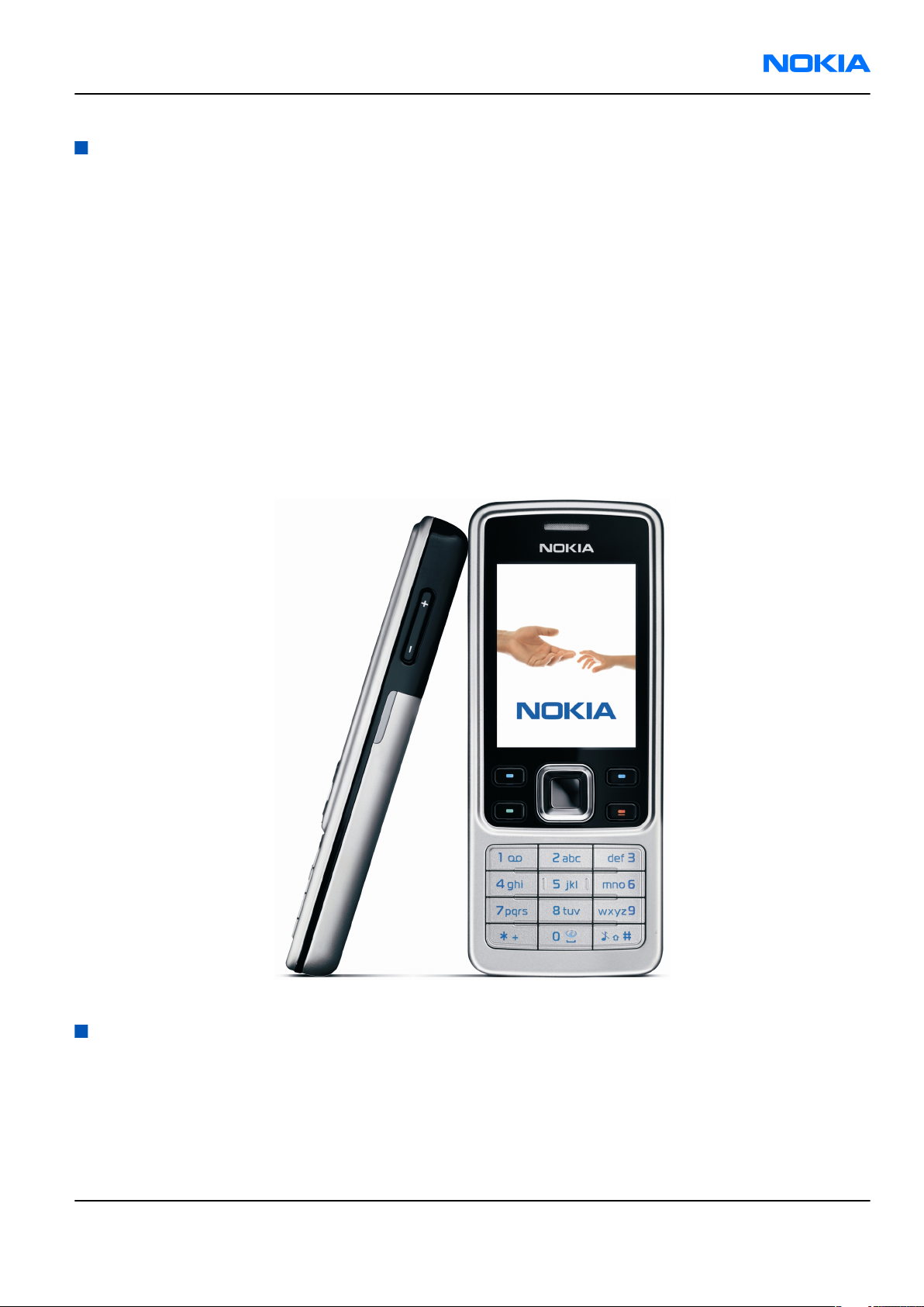
The RM-217 and RM-222 are class 4 (max 2W) GSM triband hand portable phones, supporting GSM
850/1800/1900 (RM-222) and 900/1800/1900 (RM-217) bands, respectively. The RM-217/222 also supports
EGPRS and GPRS (Packed data). It is a class B&C terminal, supporting EGPRS multislot class 10 (4Rx + 1Tx and
3Rx + 2Tx) and GPRS multislot class 10 (4+1, 3+2).
The RM-217/222 is MMS (Multimedia Messaging Services) version 1.2 enabled phone with a QVGA 240x320
pixel, active TFT 16.7 million colour display. It also has an integrated 2 Mpix digital camera with a 8 x digtal
zoom.
The RM-217/222 has a 3GPP video player/recorder, FM stereo radio and a music player, and it supports
Bluetooth 2.0 + EDR standard as well as microSD card with hotswap possibility.
The XHTML/WAP browser in RM-217/222 is compatible with the version 2.0 specifications and it supports
HTTP/TCP/IP stack.
In addition the RM-217/222 is a Java-enabled phone (JavaTM 2 Platform, Micro Edition, for embedded devices).
It supports MIDP Java 2.0 with additionally APIs.
The supported user interface is S40, that is, RM-217/222 software is based on the ISA platform.
Figure 1 View of RM-217/222
Features
Phone features
General features
• Demo mode (phone demo without SIM card)
Issue 1 COMPANY CONFIDENTIAL Page 1 –5
Copyright © 2007 Nokia. All rights reserved.
Page 18
RM-217; RM-222
Nokia Customer Care General information
Hardware features
Display and keypad features
• Main display: Active TFT QVGA display supporting up to 16,7 million colors (320 x 240 pixels, 2 inches active
area)
• Power switch
• Side volume keys
Hardware characteristics
• Monoblock phone
• 2-Mpix camera with 8 x digital zoom
• Hotswap µSD memory card slot (under the battery cover)
• Stereo FM radio and music player
• Integrated handsfree speaker
• Internal vibra
• Bluetooth
• 2.0 mm DC charger plug interface
• Mini-USB connector
• 2.5mm Nokia AV connector
Software and User interface features
Software features
• ISA OS 8.0s Platform
•
Nokia Series 40 User interface (UI): JavaTM MIDP 2.0
UI features
Imaging • 2.0-megapixel camera with 8x digital zoom (1600 x 1200 pixel
resolution)
• Full-screen viewfinder
• PictBridge printing via USB cable
Multimedia • MP3 player supporting formats including MP3, Midi, AAC, AAC+, enhanced
AAC+, WMA
• FM stereo radio, Visual Radio and music player
• 3GPP video player/recorder
• MP3 ringing tones, True tones and MIDI tones, with support of 64
polyphony
Memory functions • Combo memory with 32 MB flash and 16 MB RAM – about 7 MB user
memory (for gallery and applications, contacts, notes, calendar entries)
• Hotswap microSD memory card slot supporting up to 2GB microSD
memory cards (available as enhancements)
Page 1 –6 COMPANY CONFIDENTIAL Issue 1
Copyright © 2007 Nokia. All rights reserved.
Page 19
RM-217; RM-222
General information Nokia Customer Care
Messaging • Simplified messaging with recently used contacts log and groups
• Email: Access your work and private email accounts; supports SMTP,
POP3, and IMAP4 protocols. Support for attachments (Java version)
• Audio messaging service (AMS): Record your own voice message and send
to compatible devices
• MMS OMA 1.2: Combine image, video, text, and voice clips and send as an
MMS to a compatible phone or PC; use MMS to tell your story with a multislide presentation. The MMS OMA 1.2 specification allows you to send/
receive messages up to 300 kB in size.
• Text messaging: Supports concatenated SMS, picture messaging, SMS
distribution list
• Predictive text input: Support for all major languages in Europe and AsiaPacific
• Instant Messaging (IM)
Applications • Java™ MIDP 2.0 with over-the-air download
• Pre-installed Java™-based applications and games
• SIM Application Toolkit
• Wireless Presenter
Connectivity • Nokia PC Suite with USB and Bluetooth connectivity
• Bluetooth wireless connectivity (SIM access, headset, and handsfree
profiles) incl. stereo support for headsets
• Nokia AV connector interface with USB
• FOTA (Flashing over-the-air)
• Local/remote SyncML data synchronization
Browsing • Integrated XHTML browser
• Smart content download - OMA DRM 2.0
Data transfer • EDGE (EGPRS): Class 10, download up to 236.8 kbps
• GPRS: Class 10, download up to 53.6 kbps
Note: Actual achieved speeds may vary depending on network support
• GPRS/EDGE/HSCSD/CSD for browsing and as data modem
• Downlink Advanced Receiver Performance (DARP)
Voice features • Push To Talk: Select the person or group you want to talk to and press
the Push To Talk key to communicate
• Enhanced voice dialling with SIND: Speaker-independent name dialling
for easy call handling
• Integrated handsfree speaker with a new high quality speaker for better
audio experience (stereo widening effects when attaching the headset)
• Voice commands
• Voice recorder
Issue 1 COMPANY CONFIDENTIAL Page 1 –7
Copyright © 2007 Nokia. All rights reserved.
Page 20
RM-217; RM-222
Nokia Customer Care General information
Digital services • User Interface (UI) themes including e.g. animated wallpapers,
screensavers, color schemes, ringing tones
• Ringing tones: Video, MP3 ringing tones, True Tones and MIDI ringing,
alert, and gaming tones with support of 64 polyphony
• OTA download possibility for: Themes, True Tones, MP3 ringing tones,
MIDI ringing tones, screensavers, wallpapers, 3GPP streaming, images
and videos, Series 40 Java games and applications
Personal information
management (PIM)
• Organizer with alarm clock, calendar, to-do list, notes, calculator,
countdown timer, and stopwatch
• Manage your time and information with the enhanced calendar that can
be synchronized, for example, with Microsoft and Lotus PIM application
calendars by using the Nokia PC Suite
Call management • Speed dialling
• Logs: Keeps lists of your dialled, received, and missed calls
• Automatic answer (works with headset or car kit only)
• Call waiting, call hold, call divert, call timer
Accessories
Table 1 Audio
Type Name
AD-42W Wireless audio gateway
HS-40 Mono headset
HS-16, HS-42,
HS-47
BH-300,
BH-601,
BH-700,
BH-800,
BH-900,
HS-4W,
HS-50W
Stereo headsets
Wireless mono headsets
HS-21W,
Wireless stereo headsets
HS-24W,
HS-25W,
HS-26W,
HS-34W,
HS-36W,
HS-37W,
HS-57W,
HS-58W
Page 1 –8 COMPANY CONFIDENTIAL Issue 1
Copyright © 2007 Nokia. All rights reserved.
Page 21
RM-217; RM-222
General information Nokia Customer Care
Table 2 Battery and chargers
Type Name
Note: This phone is charged through the smaller Nokia standard interface (2.0 mm plug). The 3.5 mm
standard charger can be used together with the CA-44 charger adapter.
AC-3/AC-5 Compact charger
AC-4 Travel charger
BL-4C Battery 860 mAh Li-Ion
CA-44 Charger adapter (from 3.5 mm -> 2 mm)
Table 3 Car accessories
Type Name
CK-1W Wireless car kit
CK-7W Basic universal car kit
CK-20W Car Installation Kit
CR-39 Universal holder
DC-4 Mobile charger
HF-35W Wireless Car Handsfree
N616 Car phone
Table 4 Data
Type Name
DKE-2 Mini USB connectivity cable
MU-22 1 GB µSD card
MU-26 128 MB µSD card
MU-27 256 MB µSD card
MU-28 512 MB µSD card
MU-37 2 GB µSD card
Table 5 Imaging
Type Name
PT-6 Remote camera
Issue 1 COMPANY CONFIDENTIAL Page 1 –9
Copyright © 2007 Nokia. All rights reserved.
Page 22

RM-217; RM-222
Nokia Customer Care General information
(This page left intentionally blank.)
Page 1 –10 COMPANY CONFIDENTIAL Issue 1
Copyright © 2007 Nokia. All rights reserved.
Page 23

Nokia Customer Care
2 — Parts and layouts
Issue 1 COMPANY CONFIDENTIAL Page 2 –1
Copyright © 2007 Nokia. All rights reserved.
Page 24

RM-217; RM-222
Nokia Customer Care Parts and layouts
(This page left intentionally blank.)
Page 2 –2 COMPANY CONFIDENTIAL Issue 1
Copyright © 2007 Nokia. All rights reserved.
Page 25

RM-217; RM-222
Parts and layouts Nokia Customer Care
Table of Contents
Exploded view.........................................................................................................................................................2–5
Exploded view ...................................................................................................................................................2–5
Mechanical spare parts overview ....................................................................................................................2–6
Parts list...................................................................................................................................................................2–7
Mechanical spare parts list...............................................................................................................................2–7
Component parts list (1ywa_32a)....................................................................................................................2–8
Swap units ...................................................................................................................................................... 2–24
Component layouts ............................................................................................................................................. 2–25
Component layout - top (1ywa_32a)............................................................................................................ 2–25
Component layout - bottom (1ywa_32a)..................................................................................................... 2–26
List of Tables
Table 6 Swap phones.......................................................................................................................................... 2–24
Table 7 Lightswap ............................................................................................................................................... 2–24
Issue 1 COMPANY CONFIDENTIAL Page 2 –3
Copyright © 2007 Nokia. All rights reserved.
Page 26

RM-217; RM-222
Nokia Customer Care Parts and layouts
(This page left intentionally blank.)
Page 2 –4 COMPANY CONFIDENTIAL Issue 1
Copyright © 2007 Nokia. All rights reserved.
Page 27
RM-217; RM-222
Parts and layouts Nokia Customer Care
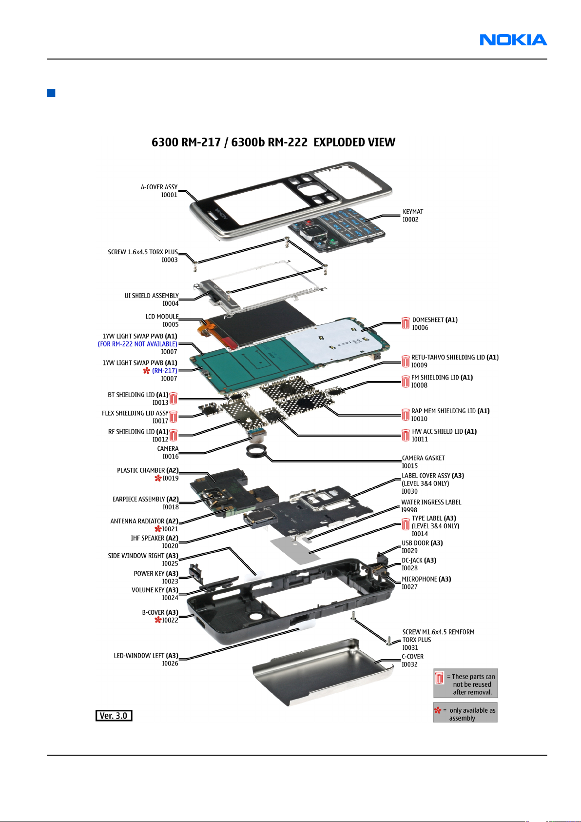
Exploded view
Exploded view
Issue 1 COMPANY CONFIDENTIAL Page 2 –5
Copyright © 2007 Nokia. All rights reserved.
Page 28
RM-217; RM-222
Nokia Customer Care Parts and layouts
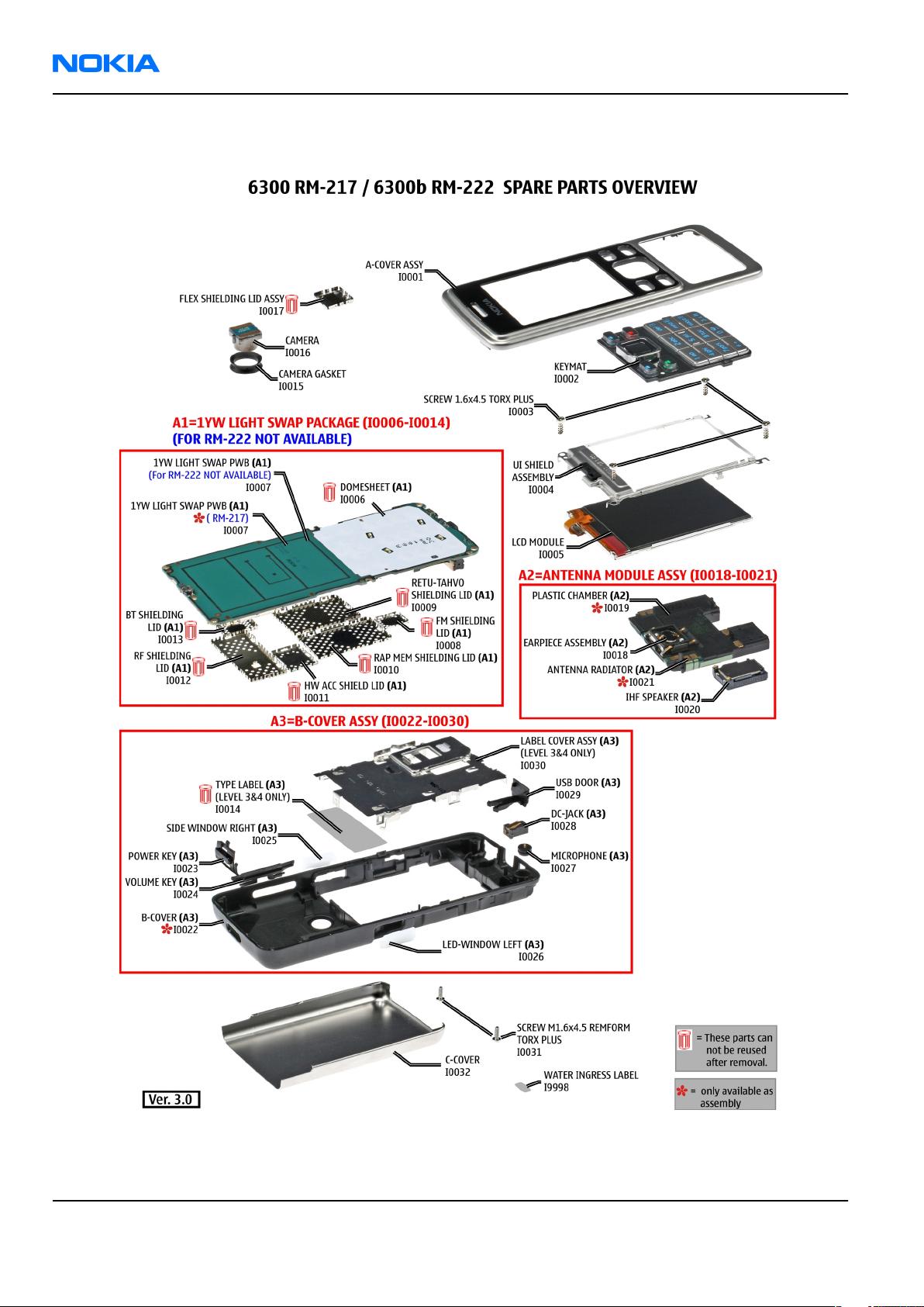
Mechanical spare parts overview
Page 2 –6 COMPANY CONFIDENTIAL Issue 1
Copyright © 2007 Nokia. All rights reserved.
Page 29
RM-217; RM-222
Parts and layouts Nokia Customer Care
Parts list
Mechanical spare parts list
Note: For Nokia product codes, please refer to the latest Service Bulletins on the Partner Website (PWS).
To ensure you are always using the latest codes, please check the PWS on a daily basis.
Ax and in bold = ASSY
"-" = NOT AVAILABLE
"XXXXXXX" = VARIANTS
"???????" = Code available in Bulletin
I0xx = ITEM codes for upper or mono block
I1xx = ITEM codes for hinge block
I2xx = ITEM codes for lower block
I3xx = ITEM codes for soldered spare parts on the upper, hinge or lower block and not exchangeable
ITEM/
CIRCUIT
REF.
QTY PART NAME Note
I0001 1 A-COVER ASSY
I0002 1 KEYMAT
I0003 4 SCREW 1.6X4.5 TORX PLUS
I0004 1 UI SHIELD ASSEMBLY
I0005 1 LCD MODULE
A1 1 1YW LIGHT SWAP PACKAGE (I0006 -
I0014)
I0006 1 DOMESHEET Cannot be reused when removed.
I0007 1 1YW LIGHT SWAP PWB
I0008 1 FM SHIELDING LID Cannot be reused when removed.
I0009 1 RETU-TAHVO SHIELDING LID Cannot be reused when removed.
I0010 1 RAP MEM SHIELDING LID Cannot be reused when removed.
I0011 1 HWA SHIELDING LID Cannot be reused when removed.
I0012 1 RF SHIELDING LID Cannot be reused when removed.
I0013 1 BT SHIELDING LID Cannot be reused when removed.
I0014 1 TYPE LABEL Cannot be reused when removed.
I0015 1 CAMERA GASKET
I0016 1 CAMERA
I0017 1 FLEX SHIELDING LID ASSY Cannot be reused when removed.
A2 1
ANTENNA MODULE ASSY (I0018 I0021)
I0018 1 EARPIECE ASSEMBLY
Issue 1 COMPANY CONFIDENTIAL Page 2 –7
Copyright © 2007 Nokia. All rights reserved.
Page 30
RM-217; RM-222
Nokia Customer Care Parts and layouts
ITEM/
CIRCUIT
REF.
I0019 1 PLASTIC CHAMBER
I0020 1 IHF SPEAKER
I0021 1 ANTENNA RADIATOR
A3 1 B-COVER ASSY (I0022 - I0030)
I0022 1 B-COVER
I0023 1 POWER KEY
I0024 1 VOLUME KEY
I0025 1 SIDE WINDOW RIGHT
I0026 1 LED WINDOW LEFT
I0027 1 MICROPHONE
I0028 1 DC JACK
QTY PART NAME Note
I0029 1 USB DOOR
I0030 1 LABEL COVER ASSY
I0031 2 SCREW 1.6 x 4.5 REMFORM TORX PLUS
I0032 1 C-COVER
I9998 1 WATER INGRESS LABEL
Note
Antenna Module is marked 850 or 900 to enable identification of different versions by regions.
Component parts list (1ywa_32a)
Item Side Grid Description and value
RETU TAHVO SHIELD ASSY
A2200 Bottom K 3 SHIELD_040_025976
A2400 Bottom T 3 SHIELD_0264510
A2800 Bottom K 7 SHIELD_040_025979
040-025976 P2912
FLEX SHIELD FRAME 031886
P2908
RAP_MEM SHIELD ASSY
040-025979 P2912
HW_ACC ASSEMBLY 040-025020
A3300 Bottom O 8 SHIELD_040_025020
A6000 Bottom Q 2 SHIELD_040_031454 BT SHIELD ASSY 031454 P2908
A6100 Bottom G 6 SHIELD_040_031457 FM SHIELD ASSY 031457 P2908
A7000 Bottom R 6 SHIELD_040_009342 RF ASSEMBLY 040-009342 P2465
Page 2 –8 COMPANY CONFIDENTIAL Issue 1
Copyright © 2007 Nokia. All rights reserved.
P2912
Page 31

RM-217; RM-222
Parts and layouts Nokia Customer Care
Item Side Grid Description and value
MIC_OBE_415S42_RC3310C
B2100 Bottom B 8
B2101 Bottom T 6 SPEAKER_LTR_RDF_COMB
B2200 Bottom M 3 CRYSTAL_3.3X1.6_H0.9
C2000 Top A 4 0402C CHIPCAP NP0 27P J 50V 0402
C2001 Top A 3 0603C_H0.95 CHIPCAP X5R 470N K 25V 0603
C2002 Top A 5 0603C CHIPCAP X7R 10N K 50V 0603
C2008 Bottom C 2 0402C CHIPCAP X7R 1N0 K 50V 0402
C2030 Bottom E 5 0402C CHIPCAP NP0 270P J 50V 0402
C2031 Bottom E 5 0402C CHIPCAP X7R 1N0 K 50V 0402
C2032 Bottom D 5 0402C CHIPCAP X7R 10N K 16V 0402
C2033 Bottom E 4 0402C CHIPCAP X7R 33N K 10V 0402
C2034 Bottom E 4 0402C CHIPCAP X7R 33N K 10V 0402
C2035 Bottom C 5 0402C CHIPCAP NP0 27P J 50V 0402
C2040 Bottom H 5 0603C CHIPCAP X5R 2U2 K 6V3 0603
L_CARBON
CLAPTON EMC MICROPHONE MOD
-42DB
EARP RDF-07A 32OHM
10.86x7.40.2.25
CRYSTAL 32.768KHZ +/-30PPM
12.5PF
C2041 Bottom C 3 0603C CHIPCAP X5R 2U2 K 6V3 0603
C2042 Bottom D 4 0402C CHIPCAP X7R 1N0 K 50V 0402
C2043 Bottom C 4 0402C CHIPCAP X7R 1N0 K 50V 0402
C2044 Bottom C 4 0402C CHIPCAP NP0 18P J 50V 0402
C2045 Bottom D 5 0402C CHIPCAP NP0 18P J 50V 0402
C2046 Bottom C 4 0402C_H0.6 CHIPCAP X5R 100N K 16V 0402
C2047 Bottom C 4 0603C CHIPCAP X5R 4U7 K 6.3V 0603
C2048 Bottom C 3 0603C CHIPCAP X5R 2U2 K 6V3 0603
C2049 Bottom H 5 0603C CHIPCAP X5R 1U K 6V3 0603
C2050 Bottom D 5 0402C CHIPCAP X7R 10N K 16V 0402
C2051 Bottom H 5 0603C CHIPCAP X5R 1U K 6V3 0603
C2052 Bottom C 5 0402C CHIPCAP NP0 27P J 50V 0402
C2071 Bottom Q 3 0402C CHIPCAP NP0 27P J 50V 0402
C2073 Bottom S 2 TANT_C_6.2X3.4_H1.7 CHIPTCAP 150U M 10V 6X3.2X1.5
C2074 Bottom L 2 0402C CHIPCAP X7R 10N K 16V 0402
C2076 Bottom Q 4 0402C CHIPCAP X7R 10N K 16V 0402
C2077 Bottom M 2 0603C CHIPCAP X5R 1U K 6V3 0603
C2078 Bottom M 2 0402C CHIPCAP NP0 27P J 50V 0402
C2079 Bottom E 4 0402C CHIPCAP X7R 1N0 K 50V 0402
Issue 1 COMPANY CONFIDENTIAL Page 2 –9
Copyright © 2007 Nokia. All rights reserved.
Page 32

RM-217; RM-222
Nokia Customer Care Parts and layouts
Item Side Grid Description and value
C2080 Bottom E 4 0402C CHIPCAP X7R 10N K 16V 0402
C2100 Bottom G 5 0402C CHIPCAP X7R 33N K 10V 0402
C2101 Bottom F 5 0402C CHIPCAP X7R 33N K 10V 0402
C2102 Bottom H 5 0603C CHIPCAP X5R 2U2 K 6V3 0603
C2103 Bottom O 1 0402C CHIPCAP NP0 27P J 50V 0402
C2104 Bottom O 2 0402C CHIPCAP NP0 27P J 50V 0402
C2200 Bottom M 5 0603C CHIPCAP X5R 1U K 6V3 0603
C2201 Bottom M 2 0603C CHIPCAP X5R 1U K 6V3 0603
C2202 Bottom N 2 0402C CHIPCAP X7R 1N0 K 50V 0402
C2203 Bottom M 4 0402C CHIPCAP X7R 1N0 K 50V 0402
C2204 Bottom M 4 0402C CHIPCAP X7R 1N0 K 50V 0402
C2205 Bottom M 4 0402C CHIPCAP X7R 1N0 K 50V 0402
C2206 Bottom M 4 0402C CHIPCAP X7R 1N0 K 50V 0402
C2207 Bottom N 2 0402C CHIPCAP X7R 1N0 K 50V 0402
C2208 Bottom N 3 0402C CHIPCAP NP0 27P J 50V 0402
C2209 Bottom N 3 0402C CHIPCAP NP0 22P J 50V 0402
C2210 Bottom K 3 0603C CHIPCAP X5R 1U K 16V 0603
C2211 Bottom K 3 0805C CHIPCAP X5R 4U7 K 10V 0805
C2212 Bottom K 3 0402C CHIPCAP X5R 1U5 K 4V 0402
C2213 Bottom L 3 0402C CHIPCAP X5R 1U5 K 4V 0402
C2214 Bottom L 2 0402C CHIPCAP X5R 1U5 K 4V 0402
C2215 Bottom L 2 0402C CHIPCAP X5R 1U5 K 4V 0402
C2216 Bottom L 2 0402C CHIPCAP X5R 1U5 K 4V 0402
C2217 Bottom M 3 0402C CHIPCAP X5R 1U5 K 4V 0402
C2219 Bottom M 2 0402C CHIPCAP X5R 1U5 K 4V 0402
C2220 Bottom K 3 0402C CHIPCAP X5R 1U5 K 4V 0402
C2221 Bottom K 2 0603C CHIPCAP X5R 1U K 6V3 0603
C2222 Bottom K 2 0603C CHIPCAP X5R 1U K 6V3 0603
C2223 Bottom L 4 0402C CHIPCAP X7R 10N K 16V 0402
C2224 Bottom M 4 0402C CHIPCAP X7R 10N K 16V 0402
C2225 Bottom M 2 0603C CHIPCAP X5R 1U K 6V3 0603
C2226 Bottom L 2 0603C CHIPCAP X5R 1U K 6V3 0603
C2227 Bottom K 3 0603C CHIPCAP X5R 1U K 6V3 0603
C2228 Bottom L 2 0603C CHIPCAP X5R 1U K 6V3 0603
C2230 Bottom M 3 0603C CHIPCAP X5R 1U K 6V3 0603
Page 2 –10 COMPANY CONFIDENTIAL Issue 1
Copyright © 2007 Nokia. All rights reserved.
Page 33

RM-217; RM-222
Parts and layouts Nokia Customer Care
Item Side Grid Description and value
C2231 Bottom K 5 0805C CHIPCAP X5R 10U M 6V3 0805
C2232 Bottom L 2 0603C CHIPCAP X5R 1U K 6V3 0603
C2270 Bottom L 5 0402C CHIPCAP X7R 1N0 K 50V 0402
C2271 Bottom L 5 0402C CHIPCAP X7R 1N0 K 50V 0402
C2272 Bottom L 5 0402C CHIPCAP X7R 1N0 K 50V 0402
C2273 Bottom K 4 0402C CHIPCAP X7R 1N0 K 50V 0402
C2274 Bottom K 4 0402C CHIPCAP X7R 1N0 K 50V 0402
C2275 Bottom K 4 0402C CHIPCAP X7R 1N0 K 50V 0402
C2281 Bottom L 2 0603C CHIPCAP X5R 1U K 6V3 0603
C2300 Bottom J 4 0402C CHIPCAP X7R 10N K 16V 0402
C2301 Bottom I 4 0805C CHIPCAP X5R 22U M 6V3 0805
C2302 Bottom K 5 0805C CHIPCAP X5R 22U M 6V3 0805
C2303 Bottom I 3 0603C CHIPCAP X5R 1U K 6V3 0603
C2304 Bottom K 4 0402C CHIPCAP X7R 10N K 16V 0402
C2305 Bottom I 2 0603C CHIPCAP X5R 1U K 6V3 0603
C2306 Bottom I 4 0603C CHIPCAP X5R 1U K 6V3 0603
C2307 Bottom I 4 0603C CHIPCAP X5R 1U K 6V3 0603
C2309 Bottom I 5 0805C CHIPCAP X5R 22U M 6V3 0805
C2312 Bottom I 3 0603C CHIPCAP X5R 1U K 6V3 0603
C2313 Bottom I 3 0603C CHIPCAP X5R 1U K 6V3 0603
C2314 Bottom J 2 0805C CHIPCAP X5R 4U7 K 10V 0805
C2315 Bottom K 2 0805C CHIPCAP X5R 4U7 M 25V 0805
C2317 Bottom J 2 0402C CHIPCAP NP0 27P J 50V 0402
C2403 Bottom N 2 0402C CHIPCAP NP0 47P J 50V 0402
C2404 Bottom T 2 0402C CHIPCAP X7R 4N7 K 25V 0402
C2405 Bottom T 4 0402C_H0.6 CHIPCAP X5R 100N K 16V 0402
C2413 Bottom I 2 0402C CHIPCAP NP0 27P J 50V 0402
C2414 Bottom T 2 0402C CHIPCAP NP0 27P J 50V 0402
C2415 Bottom T 4 0402C CHIPCAP NP0 27P J 50V 0402
C2416 Bottom T 3 0402C_H0.6 CHIPCAP X5R 100N K 16V 0402
C2417 Bottom T 3 0402C_H0.6 CHIPCAP X5R 100N K 16V 0402
C2418 Bottom T 3 0402C CHIPCAP NP0 27P J 50V 0402
C2700 Bottom H 2 0402C_H0.6 CHIPCAP X5R 100N K 16V 0402
C2701 Bottom H 2 0402C CHIPCAP NP0 27P J 50V 0402
C2800 Bottom L 8 0402C_H0.6 CHIPCAP X5R 100N K 16V 0402
Issue 1 COMPANY CONFIDENTIAL Page 2 –11
Copyright © 2007 Nokia. All rights reserved.
Page 34

RM-217; RM-222
Nokia Customer Care Parts and layouts
Item Side Grid Description and value
C2801 Bottom N 8 0402C_H0.6 CHIPCAP X5R 100N K 16V 0402
C2802 Bottom M 8 0402C_H0.6 CHIPCAP X5R 100N K 16V 0402
C2803 Bottom L 8 0402C_H0.6 CHIPCAP X5R 100N K 16V 0402
C2804 Bottom N 8 0402C_H0.6 CHIPCAP X5R 100N K 16V 0402
C2805 Bottom K 6 0402C_H0.6 CHIPCAP X5R 100N K 16V 0402
C2807 Bottom N 8 0603C CHIPCAP X5R 1U K 6V3 0603
C2808 Bottom M 8 0402C_H0.6 CHIPCAP X5R 100N K 16V 0402
C2809 Bottom M 8 0402C_H0.6 CHIPCAP X5R 100N K 16V 0402
C2810 Bottom K 8 0402C_H0.6 CHIPCAP X5R 100N K 16V 0402
C2811 Bottom K 6 0402C_H0.6 CHIPCAP X5R 100N K 16V 0402
C2812 Bottom L 8 0402C_H0.6 CHIPCAP X5R 100N K 16V 0402
C2813 Bottom N 6 0402C_H0.6 CHIPCAP X5R 100N K 16V 0402
C2814 Bottom M 8 0402C_H0.6 CHIPCAP X5R 100N K 16V 0402
C2815 Bottom K 8 0402C_H0.6 CHIPCAP X5R 100N K 16V 0402
C2816 Bottom K 8 0402C CHIPCAP NP0 27P J 50V 0402
C2818 Bottom K 6 0402C_H0.6 CHIPCAP X5R 100N K 16V 0402
C2819 Bottom K 8 0402C_H0.6 CHIPCAP X5R 100N K 16V 0402
C2820 Bottom N 6 0402C_H0.6 CHIPCAP X5R 100N K 16V 0402
C2821 Bottom N 6 0402C CHIPCAP NP0 27P J 50V 0402
C2831 Bottom N 7 0402C CHIPCAP NP0 1P0 C 50V 0402
C3000 Bottom I 6 0402C_H0.6 CHIPCAP X5R 100N K 16V 0402
C3001 Bottom J 6 0402C CHIPCAP X7R 10N K 16V 0402
C3002 Bottom J 6 0402C_H0.6 CHIPCAP X5R 100N K 16V 0402
C3003 Bottom K 8 0402C CHIPCAP X7R 10N K 16V 0402
C3004 Bottom K 8 0402C_H0.6 CHIPCAP X5R 100N K 16V 0402
C3005 Bottom J 8 0402C_H0.6 CHIPCAP X5R 100N K 16V 0402
C3006 Bottom I 8 0402C_H0.6 CHIPCAP X5R 100N K 16V 0402
C3007 Bottom J 8 0402C CHIPCAP X7R 10N K 16V 0402
C3008 Bottom J 8 0402C_H0.6 CHIPCAP X5R 100N K 16V 0402
C3009 Bottom I 8 0402C_H0.6 CHIPCAP X5R 100N K 16V 0402
C3010 Bottom N 5 0402C_H0.6 CHIPCAP X5R 100N K 16V 0402
C3013 Bottom K 7 0402C CHIPCAP NP0 27P J 50V 0402
C3014 Bottom K 7 0402C CHIPCAP NP0 68P J 50V 0402
C3100 Bottom E 2 0402C CHIPCAP NP0 27P J 50V 0402
C3115 Bottom O 7 0402C CHIPCAP X5R 1U K 6V3 0402
Page 2 –12 COMPANY CONFIDENTIAL Issue 1
Copyright © 2007 Nokia. All rights reserved.
Page 35

RM-217; RM-222
Parts and layouts Nokia Customer Care
Item Side Grid Description and value
C3116 Bottom O 7 0402C CHIPCAP X7R 10N K 16V 0402
C3200 Bottom G 8 0402C_H0.6 CHIPCAP X5R 100N K 16V 0402
C3201 Bottom H 8 0402C CHIPCAP X5R 1U K 6V3 0402
C3202 Bottom H 7 0402C CHIPCAP X7R 10N K 16V 0402
C3203 Bottom G 8 0402C CHIPCAP X5R 1U K 6V3 0402
C3204 Bottom H 7 0402C_H0.6 CHIPCAP X5R 100N K 16V 0402
C3210 Bottom G 8 0402C CHIPCAP NP0 27P J 50V 0402
C3211 Top D 8 0402C CHIPCAP NP0 27P J 50V 0402
C3300 Bottom P 6 0402C_H0.6 CHIPCAP X5R 100N K 16V 0402
C3301 Bottom N 5 0402C_H0.6 CHIPCAP X5R 100N K 16V 0402
C3302 Bottom N 4 0402C CHIPCAP X5R 220N K 6.3V 0402
C3303 Bottom O 8 0402C_H0.6 CHIPCAP X5R 100N K 16V 0402
C3304 Bottom O 8 0402C CHIPCAP X7R 10N K 16V 0402
C3305 Bottom O 6 0603C CHIPCAP X5R 4U7 K 6.3V 0603
C3306 Bottom O 8 0603C CHIPCAP X5R 4U7 K 6.3V 0603
C3307 Bottom O 8 0603C CHIPCAP X5R 10UF 6V3 0603
C3308 Bottom N 5 0402C CHIPCAP X5R 1U K 6V3 0402
C3309 Bottom N 5 0402C CHIPCAP NP0 27P J 50V 0402
C3310 Bottom P 6 0402C CHIPCAP NP0 27P J 50V 0402
C3313 Bottom O 8 0402C CHIPCAP X7R 10N K 16V 0402
C3314 Bottom P 8 0402C CHIPCAP X7R 10N K 16V 0402
C6020 Bottom T 2 0402C CHIPCAP NP0 1P5 C 50V 0402
C6031 Bottom R 1 0402C CHIPCAP NP0 18P J 50V 0402
C6032 Bottom P 2 0402C CHIPCAP NP0 100P J 50V 0402
C6033 Bottom P 2 0402C CHIPCAP X7R 10N K 16V 0402
C6034 Bottom P 2 0402C CHIPCAP X7R 10N K 16V 0402
C6035 Bottom P 1 0402C CHIPCAP X7R 10N K 16V 0402
C6036 Bottom P 2 0402C CHIPCAP X7R 10N K 16V 0402
C6037 Bottom P 2 0402C CHIPCAP X5R 1U5 K 4V 0402
C6038 Bottom Q 1 0402C CHIPCAP X7R 10N K 16V 0402
C6039 Bottom Q 2 0402C CHIPCAP NP0 18P J 50V 0402
C6040 Bottom P 2 0402C CHIPCAP X5R 1U K 6V3 0402
C6051 Bottom Q 2 0402C CHIPCAP NP0 2P7 C 50V 0402
C6052 Bottom Q 2 0402C CHIPCAP NP0 2P7 C 50V 0402
C6055 Bottom Q 2 0603C CHIPCAP X5R 1U K 6V3 0603
Issue 1 COMPANY CONFIDENTIAL Page 2 –13
Copyright © 2007 Nokia. All rights reserved.
Page 36

RM-217; RM-222
Nokia Customer Care Parts and layouts
Item Side Grid Description and value
C6100 Bottom G 7 0402C_H0.6 CHIPCAP X5R 100N K 16V 0402
C6101 Bottom H 6 0402C_H0.6 CHIPCAP X5R 100N K 16V 0402
C6102 Bottom G 7 0402C CHIPCAP X7R 10N K 16V 0402
C6103 Bottom G 7 0402C_H0.6 CHIPCAP X5R 100N K 16V 0402
C6104 Bottom H 6 0402C CHIPCAP NP0 47P J 50V 0402
C6105 Bottom G 6 0402C CHIPCAP NP0 100P J 50V 0402
C6106 Bottom H 6 0402C CHIPCAP NP0 27P J 50V 0402
CHIP ARRAY X5R 2X100N M 10V
C6107 Bottom H 6 0405_2_P0.65_AVX
C6108 Bottom H 6 0405_2_P0.65_AVX
C6109 Bottom G 6 0402C CHIPCAP X5R 1U5 K 4V 0402
C7000 Bottom U 8 0402C CHIPCAP NP0 1P5 C 50V 0402
0405
CHIP ARRAY X5R 2X100N M 10V
0405
C7001 Bottom T 8 0402C CHIPCAP NP0 1P5 C 50V 0402
C7010 Bottom N 5 0402C_H0.6 CHIPCAP X5R 100N K 16V 0402
C7011 Bottom N 4 0402C_H0.6 CHIPCAP X5R 100N K 16V 0402
C7012 Bottom N 5 0402C_H0.6 CHIPCAP X5R 100N K 16V 0402
C7013 Bottom N 4 0402C_H0.6 CHIPCAP X5R 100N K 16V 0402
C7501 Bottom S 5 0402C CHIPCAP NP0 2P7 C 50V 0402
C7502 Bottom Q 5 0402C CHIPCAP NP0 0P5 C 50V 0402
C7503 Bottom Q 4 0603C CHIPCAP X5R 1U K 6V3 0603
C7504 Bottom S 5 0603C CHIPCAP X5R 1U K 6V3 0603
C7505 Bottom Q 4 0402C CHIPCAP X5R 1U K 6V3 0402
C7506 Bottom Q 4 0402C CHIPCAP X5R 1U K 6V3 0402
C7507 Bottom Q 4 0402C CHIPCAP X7R 10N K 16V 0402
C7508 Bottom Q 5 0402C CHIPCAP NP0 18P J 50V 0402
C7509 Bottom R 4 0402C CHIPCAP X7R 10N K 16V 0402
C7511 Bottom R 4 0603C CHIPCAP NP0 2N2 G 16V 0603
C7513 Bottom Q 4 0402C CHIPCAP X7R 10N K 16V 0402
C7515 Bottom S 4 0402C CHIPCAP NP0 4P7 C 50V 0402
C7516 Bottom S 4 0402C CHIPCAP NP0 470P J 50V 0402
C7518 Bottom Q 5 0402C_H0.6 CHIPCAP X5R 100N K 16V 0402
C7520 Bottom S 8 0402C CHIPCAP NP0 3P3 C 50V 0402
C7521 Bottom S 8 0402C CHIPCAP NP0 1P5 C 50V 0402
C7522 Bottom Q 8 0402C CHIPCAP NP0 1P8 C 50V 0402
Page 2 –14 COMPANY CONFIDENTIAL Issue 1
Copyright © 2007 Nokia. All rights reserved.
Page 37

RM-217; RM-222
Parts and layouts Nokia Customer Care
Item Side Grid Description and value
C7523 Bottom S 8 0402C CHIPCAP X5R 1U K 6V3 0402
C7524 Bottom Q 7 0402C CHIPCAP X5R 1U K 6V3 0402
C7525 Bottom Q 9 0402C CHIPCAP NP0 18P J 50V 0402
C7560 Bottom R 3 0402C CHIPCAP NP0 1P2 C 50V 0402
C7561 Bottom R 4 0402C CHIPCAP X7R 820P J 50V 0402
C7562 Bottom Q 6 0402C CHIPCAP NP0 39P J 50V 0402
C7563 Bottom Q 5 0402C CHIPCAP NP0 47P J 50V 0402
C7564 Bottom S 4 0402C CHIPCAP X7R 10N K 16V 0402
C7565 Bottom Q 5 0402C CHIPCAP NP0 47P J 50V 0402
C7566 Bottom R 4 0402C CHIPCAP NP0 4P7 C 50V 0402
RETU 3.02 LF TSA1GJWE
D2200 Bottom L 3 TFBGA_108
D2800 Bottom L 7 UBGA_289
TFBGA108
RAPGSM PA v1.1 LF C027
uBGA289
COMBO 256M NOR + 128M DDR
D3000 Bottom J 7 FBGA133_11.1X10.1
D3300 Bottom O 7 TFBGA84 HW ACCELERATOR STV0984N
E2001 Bottom D 4 PICK_PLACE_9900821 No description in PDM
E2002 Bottom A 6 PICK_PLACE_9900821 No description in PDM
E2003 Bottom D 4 PICK_PLACE_9900821 No description in PDM
E2010 Bottom A 7 PICK_PLACE_9900821 No description in PDM
E2070 Bottom P 3 PICK_PLACE_9900821 No description in PDM
E2071 Bottom P 3 PICK_PLACE_9900821 No description in PDM
E2075 Bottom P 4 PICK_PLACE_9900821 No description in PDM
E2101 Bottom Q 6 CLIP_040_034164 No description in PDM
E2102 Bottom Q 9 CLIP_040_034164 No description in PDM
E2103 Bottom U 6 BT_PAD_9900503 No description in PDM
E2104 Bottom T 6 BT_PAD_9900503 No description in PDM
E2105 Bottom U 7 BT_PAD_9900503 No description in PDM
E2106 Bottom T 6 BT_PAD_9900503 No description in PDM
DRAM FBGA133
E2401 Top C 9 PICK_PLACE_9900821 No description in PDM
E2402 Top C 1 PICK_PLACE_9900821 No description in PDM
E2403 Top N 1 PICK_PLACE_9900821 No description in PDM
E2405 Top T 9 PICK_PLACE_9900821 No description in PDM
E2407 Top N 9 PICK_PLACE_9900821 No description in PDM
E2506 Top T 1 PICK_PLACE_9900821 No description in PDM
Issue 1 COMPANY CONFIDENTIAL Page 2 –15
Copyright © 2007 Nokia. All rights reserved.
Page 38

RM-217; RM-222
Nokia Customer Care Parts and layouts
Item Side Grid Description and value
E6001 Bottom T 1 CLIP_040_034164 No description in PDM
E6003 Bottom T 1 CLIP_040_034164 No description in PDM
E7000 Bottom U 8 PICK_PLACE_9900821 No description in PDM
E7001 Bottom U 5 PICK_PLACE_9900821 No description in PDM
E7501 Bottom T 9 CLIP_040_034164 No description in PDM
E7502 Bottom T 9 CLIP_040_034164 No description in PDM
E7503 Bottom U 8 CLIP_040_034164 No description in PDM
F2000 Top A 5 0402_FUSE_AVX_H0.5 SM FUSE FF 2A 32V 0402
RTC BACKUP CAPAC 311 SIZE FOR
G2200 Bottom C 2 BATTER_EECEP
G7500 Bottom S 4 VCO_DCS02733 VCO 3296-3980MHZ 4-BAND
G7501 Bottom Q 3 NKG3176B_H1.0 VCTCXO 38.4MHZ 2.5V 2MA
L2000 Top A 5 0603_BLM
2.6V 4UAH
FERR.BEAD 220R/100M 2A 0R05
0603
L2030 Bottom C 5 FERRITE_0402
L2031 Bottom C 4 FERRITE_0402
L2032 Bottom D 5 COIL_LK_1608
L2033 Bottom D 5 FERRITE_0402
L2034 Bottom D 5 FERRITE_0402
L2035 Bottom C 5 FERRITE_0402
L2102 Bottom Q 7 COIL_LQW1608
L2103 Bottom Q 8 COIL_LQW1608
L2104 Top A 7 0405_2_H1.0
L2105 Bottom O 2 0402L
FERRITE BEAD 0.6R 600R/100MZ
0402
FERRITE BEAD 0.6R 600R/100MZ
0402
CHIP COIL 68NH J Q12/100MHZ
0603
FERRITE BEAD 0.6R 600R/100MZ
0402
FERRITE BEAD 0.6R 600R/100MZ
0402
FERRITE BEAD 0.6R 600R/100MZ
0402
CHIP COIL 56N J Q38/200MHZ
0603
CHIP COIL 56N J Q38/200MHZ
0603
CHIP BEAD ARRAY 2X1000R 0R75
0405
FERR.BEAD 240R/100M 0.4A 0R4
0402
FERR.BEAD 240R/100M 0.4A 0R4
L2106 Bottom O 2 0402L
L2202 Bottom M 2 0603_BLM
L2207 Bottom N 4 0402L
Page 2 –16 COMPANY CONFIDENTIAL Issue 1
Copyright © 2007 Nokia. All rights reserved.
0402
FERR.BEAD 220R/100M 2A 0R05
0603
FERR.BEAD 240R/100M 0.4A 0R4
0402
Page 39

RM-217; RM-222
Parts and layouts Nokia Customer Care
Item Side Grid Description and value
FERR.BEAD 240R/100M 0.4A 0R4
L2208 Bottom N 4 0402L
L2209 Bottom M 5 0402L
L2210 Bottom M 5 0402L
L2211 Bottom M 4 0402L
L2212 Bottom M 4 0402L
L2270 Bottom L 4 0603_BLM
L2271 Bottom L 4 0603_BLM
L2272 Bottom K 4 0603_BLM
0402
FERR.BEAD 240R/100M 0.4A 0R4
0402
FERR.BEAD 240R/100M 0.4A 0R4
0402
FERR.BEAD 240R/100M 0.4A 0R4
0402
FERR.BEAD 240R/100M 0.4A 0R4
0402
FERR.BEAD 220R/100M 2A 0R05
0603
FERR.BEAD 220R/100M 2A 0R05
0603
FERR.BEAD 220R/100M 2A 0R05
0603
L2273 Bottom K 4 0603_BLM
L2301 Bottom I 4 0603_BLM
L2302 Bottom J 4 CHOKE_SER400_H1.2
L2304 Bottom J 2 CHOKE_SER300_H1.5
L2305 Bottom I 3 FERRITE_0402
L2306 Bottom I 3 FERRITE_0402
L2402 Bottom T 3 FERRITE_0402
L2403 Bottom J 2 0402L
L2404 Bottom T 3 FERRITE_0402
L2405 Bottom O 2 FERRITE_0402
FERR.BEAD 220R/100M 2A 0R05
0603
FERR.BEAD 220R/100M 2A 0R05
0603
INDUCT WW 10U 0A65 0R35
4X4X1.2
CHOKE 22U M 0R7 0.35A
3.0X3.0X1.5
FERRITE BEAD 0.6R 600R/100MZ
0402
FERRITE BEAD 0.6R 600R/100MZ
0402
FERRITE BEAD 0.6R 600R/100MZ
0402
FERR.BEAD 240R/100M 0.4A 0R4
0402
FERRITE BEAD 0.6R 600R/100MZ
0402
FERRITE BEAD 0.6R 600R/100MZ
0402
FERRITE BEAD 0.6R 600R/100MZ
L3200 Bottom G 8 FERRITE_0402
L3301 Bottom N 6 FERRITE_0402
Issue 1 COMPANY CONFIDENTIAL Page 2 –17
Copyright © 2007 Nokia. All rights reserved.
0402
FERRITE BEAD 0.6R 600R/100MZ
0402
Page 40

RM-217; RM-222
Nokia Customer Care Parts and layouts
Item Side Grid Description and value
INDUCT WW 2.2UH 1A2 0R168
L3303 Bottom P 8 CHOKE_SER300
L3304 Bottom O 9 FERRITE_0402
L6030 Bottom Q 2 0402L
L6031 Bottom Q 2 0402L
L6032 Bottom Q 1 0402L
L6077 Bottom R 2 0402L
L6100 Bottom G 7 0402LQW
L6101 Bottom H 6 0402L_POL2
310 case size
FERRITE BEAD 0.6R 600R/100MZ
0402
CHIP COIL 2N7 +-0N3 Q29/800M
0402
CHIP COIL 2N7 +-0N3 Q29/800M
0402
CHIP COIL 22N J Q28/800MHZ
0402
FERR.BEAD 240R/100M 0.4A 0R4
0402
CHIP COIL 47N +-3%
Q25/200MHz 0402
CHIP COIL 120NH J Q8/100MHZ
0402
FERR.BEAD 240R/100M 0.4A 0R4
L7010 Bottom N 5 0402L
L7011 Bottom N 4 0402L
L7500 Bottom S 6 0402L
L7501 Bottom S 6 0402L
L7502 Bottom Q 5 FERRITE_0402
L7503 Bottom Q 8 0402L
L7504 Bottom R 6 0402L
L7505 Bottom R 6 0402L
L7515 Bottom S 4 0402L
L7561 Bottom Q 6 COIL_HK_1608 CHIP COIL 470NH J 0603
0402
FERR.BEAD 240R/100M 0.4A 0R4
0402
CHIP COIL 12N J Q31/800MHZ
0402
CHIP COIL 12N J Q31/800MHZ
0402
FERRITE BEAD 0.6R 600R/100MZ
0402
CHIP COIL 27N J Q27/800MHZ
0402
CHIP COIL 22N J Q28/800MHZ
0402
CHIP COIL 22N J Q28/800MHZ
0402
CHIP COIL 15N J Q30/800MHZ
0402
SMD VIBRA MOTOR 1.3V 90MA
M2100 Bottom C 8 VIBRA_M_KHN4NX1RA
N2030 Bottom D 5 CSP_8_2.118X1.118
N2031 Bottom C 3 XBGA_N14
Page 2 –18 COMPANY CONFIDENTIAL Issue 1
Copyright © 2007 Nokia. All rights reserved.
9000RPM
IC ANALOG SWITCH SPDT LOW
THRESHOLD CSP8
ST HEADPHONE AMPLIFIER
LM4920 uSMD14
Page 41

RM-217; RM-222
Parts and layouts Nokia Customer Care
Item Side Grid Description and value
N2300 Bottom J 3 TFBGA_84_6.15X6.15 TAHVO v5.2 LF TFBGA84
WHITE LED DRIVER 4LEDS
N2301 Bottom J 2 USMD8_1.69X1.69
N2401 Bottom G 5 SOT_666
N3200 Bottom G 8 USMD16_2.03X2.03
N3300 Bottom O 8 USMD5_1.417X1.087
N3301 Bottom O 6 USMD5_1.47X1.04_H0.675
N6030 Bottom P 2 CSP_47_3.85X4.05 BC4-ROM1.0RDL
N6100 Bottom H 7 WLCSP25_3.1X2.9 FM RECEIVER TEA5760 N1C
N7505 Bottom R 5 TFBGA144
500mW 8bump USMD8
TRX2+RX4 PEMD9 N&P 10K/47K
0W12 SOT666
VREG & LEVELSHIFT(LP3928)
USMD16
DC/DC CONV LM3671TLX-1.82V
uSMD5
VREG LP3985ITLX-2.8 NOPB
USMD5
AHNE401A TRANSCEIVER
TFBGA144
PA RF9282E6.5 GSM/EDGE
N7520 Bottom R 8 RF9282E3.6
R2007 Bottom C 2 UBGA11_1.6X2.15 ASIP SILIC USB OTG / ESD BGA11
R2008 Bottom C 2 0402R CHIPRES 0W06 220K J 0402
R2033 Bottom E 5 0402R CHIPRES 0W06 10K J 0402
R2034 Bottom E 5 0402R CHIPRES 0W06 100R J 0402
R2035 Bottom D 5 0402R CHIPRES 0W06 100K J 0402
R2036 Bottom D 5 0402R CHIPRES 0W06 10K J 0402
R2044 Bottom H 5 0402R CHIPRES 0W06 220R J 0402
R2045 Bottom E 5 0402R CHIPRES 0W06 2K2 J 0402
R2049 Bottom D 4 0402R CHIPRES 0W06 15R J 0402
R2050 Bottom C 4 0402R CHIPRES 0W06 15R J 0402
R2051 Bottom C 5 FC5_1.1X1.1
R2052 Bottom C 4 0402R CHIPRES 0W06 100K J 0402
R2070 Bottom E 2 0402_NTH5
850/900/1800/1900
ASIP TVS 4-CH BI ESD 14V 15pF
400um BGA5
NTC RES 0W1 47K J B 4050+-3%
0402
CHIP VARISTOR VWM14V VC50V
R2071 Bottom N 2 0402_VAR
R2072 Bottom E 4 0402R CHIPRES 0W06 2K2 J 0402
R2074 Bottom E 5 0402R CHIPRES 0W06 100R J 0402
R2100 Bottom H 5 FLIP_CHIP_8_1.7X1.7
Issue 1 COMPANY CONFIDENTIAL Page 2 –19
Copyright © 2007 Nokia. All rights reserved.
0402
ASIP SINGLE ENDED MICROPHONE
INTERF BGA8
Page 42

RM-217; RM-222
Nokia Customer Care Parts and layouts
Item Side Grid Description and value
R2101 Bottom H 5 0402R CHIPRES 0W06 220R J 0402
R2102 Bottom T 5 0402R CHIPRES 0W06 10R J 0402
R2103 Bottom T 5 0402R CHIPRES 0W06 10R J 0402
R2104 Top A 8 0402R CHIPRES JUMPER 0R0 0402
R2105 Top A 8 0402R CHIPRES JUMPER 0R0 0402
CHIP VARISTOR VWM14V VC50V
R2106 Bottom N 5 0402_VAR
R2107 Bottom N 5 0402_VAR
R2200 Bottom M 2 0402R CHIPRES 0W06 100K J 0402
R2201 Bottom N 2 0402R CHIPRES 0W06 120K J 0402
R2202 Bottom M 5 0402R CHIPRES JUMPER 0R0 0402
R2203 Bottom M 5 0402R CHIPRES JUMPER 0R0 0402
0402
CHIP VARISTOR VWM14V VC50V
0402
R2204 Bottom M 5 0402R CHIPRES JUMPER 0R0 0402
R2205 Bottom M 5 0402R CHIPRES JUMPER 0R0 0402
R2212 Bottom L 4 0402R CHIPRES 0W06 470R J 0402
R2213 Bottom N 3 0402R CHIPRES 0W06 4K7 J 0402
R2216 Bottom N 3 0402R CHIPRES 0W06 2M2 J 0402
R2250 Bottom N 2 0402R CHIPRES 0W06 100K J 0402
R2251 Bottom N 2 0402R CHIPRES 0W06 100K J 0402
R2303 Bottom H 3 0603R CHIPRES JUMPER 0R0 0603
R2400 Bottom G 4 0603R CHIPRES JUMPER 0R0 0603
R2406 Bottom N 2 0402R CHIPRES 0W06 27K J 0402
R2407 Bottom H 5 0402R CHIPRES 0W06 47R J 0402
R2408 Bottom G 4 0402R CHIPRES 0W06 22K J 0402
R2418 Bottom H 4 0402R CHIPRES 0W06 470R J 0402
R2419 Bottom H 5 0402R CHIPRES 0W06 470R J 0402
R2421 Bottom K 2 0402R CHIPRES 0W06 33R J 0402
R2422 Bottom G 5 0402R CHIPRES JUMPER 0R0 0402
R2423 Bottom G 5 0402R CHIPRES 0W06 22K J 0402
R2424 Bottom I 4 0402R CHIPRES 0W06 27R J 0402
R2425 Bottom G 4 0402R CHIPRES 0W06 1K0 J 0402
R2426 Bottom N 9 0402R CHIPRES 0W06 47R J 0402
R2427 Bottom L 1 0402R CHIPRES 0W06 47R J 0402
R2430 Bottom G 4 0402R CHIPRES 0W06 22K J 0402
Page 2 –20 COMPANY CONFIDENTIAL Issue 1
Copyright © 2007 Nokia. All rights reserved.
Page 43

RM-217; RM-222
Parts and layouts Nokia Customer Care
Item Side Grid Description and value
R2803 Bottom L 8 0402R CHIPRES 0W06 100R J 0402
R2804 Bottom L 8 0402R CHIPRES 0W06 100R J 0402
R3000 Bottom J 6 0402R CHIPRES 0W06 4K7 J 0402
R3002 Bottom L 8 0402R CHIPRES 0W06 10R J 0402
R3003 Bottom K 6 0402R CHIPRES 0W06 4K7 J 0402
R3004 Bottom K 7 0402R CHIPRES 0W06 4K7 J 0402
R3200 Bottom G 8 UBGA11_1.62X2.12 ASIP MMC FILTER *** PB-FREE ***
R3201 Bottom H 8 0402R CHIPRES 0W06 100K J 0402
R3202 Bottom H 8 0402R CHIPRES 0W06 100K J 0402
R3203 Bottom H 7 0402R CHIPRES 0W06 100K J 0402
R3204 Bottom H 7 0402R CHIPRES 0W06 2K2 J 0402
R3205 Bottom G 8 0402R CHIPRES 0W06 680R J 0402
R3206 Bottom G 8 0402R CHIPRES 0W06 1K2 J 0402
R3300 Bottom P 7 0402R CHIPRES 0W06 4K7 J 0402
R3301 Bottom P 8 0402R CHIPRES 0W06 4K7 J 0402
R3305 Bottom O 7 0402R CHIPRES JUMPER 0R0 0402
R3306 Bottom P 7 0402R CHIPRES 0W06 100R J 0402
R3307 Bottom P 7 0402R CHIPRES 0W06 100R J 0402
R3312 Bottom I 8 0402R CHIPRES 0W06 1K0 J 0402
R3313 Bottom I 8 0402R CHIPRES 0W06 1K0 J 0402
R3314 Bottom O 6 0402R CHIPRES 0W06 47R J 0402
R6005 Bottom N 2 0402R CHIPRES 0W06 100K J 0402
R6020 Bottom T 2 FERRIT_0402 CHIPRES JUMPER 0R0 0402
R6030 Bottom P 2 0402R CHIPRES 0W06 10K J 0402
R6031 Bottom Q 1 0402R CHIPRES 0W06 10K J 0402
R6032 Bottom P 2 0402R CHIPRES 0W06 2R2 J 0402
R6034 Bottom Q 2 0402R CHIPRES 0W06 10K J 0402
R6037 Bottom Q 1 0402R CHIPRES 0W06 100K J 0402
R6100 Bottom G 7 0402R CHIPRES 0W06 100K J 0402
R6101 Bottom G 7 0402R CHIPRES 0W06 10K J 0402
R6102 Bottom H 7 0402R CHIPRES JUMPER 0R0 0402
R6103 Bottom G 6 0402R CHIPRES 0W06 22R J 0402
R6104 Bottom G 7 0402R CHIPRES JUMPER 0R0 0402
R6105 Bottom G 6 0402R CHIPRES JUMPER 0R0 0402
R7001 Bottom T 8 0402R CHIPRES JUMPER 0R0 0402
Issue 1 COMPANY CONFIDENTIAL Page 2 –21
Copyright © 2007 Nokia. All rights reserved.
Page 44

RM-217; RM-222
Nokia Customer Care Parts and layouts
Item Side Grid Description and value
R7002 Bottom T 8 0402R CHIPRES JUMPER 0R0 0402
R7501 Bottom R 4 0402R CHIPRES 0W06 2K2 J 0402
R7502 Bottom S 5 0402R CHIPRES 0W06 10K F 0402
R7503 Bottom Q 5 0402R CHIPRES 0W06 4K7 J 0402
R7505 Bottom R 4 0402R CHIPRES 0W06 8K2 F 0402
R7506 Bottom R 5 0402R CHIPRES 0W06 10R J 0402
R7507 Bottom S 5 0402R CHIPRES 0W06 10R J 0402
R7508 Bottom R 4 0402R CHIPRES 0W06 10R J 0402
R7509 Bottom Q 4 0402R CHIPRES 0W06 22K J 0402
R7510 Bottom Q 8 0402R CHIPRES 0W06 15R J 0402
R7522 Bottom Q 8 0402R CHIPRES 0W06 27K J 0402
R7523 Bottom S 8 0402R CHIPRES JUMPER 0R0 0402
R7560 Bottom Q 6 0402R CHIPRES 0W06 100R J 0402
SM SW TACT SPST 12V SIDE KEY
S2401 Bottom O 1 SWITCH_EVQP7A01K
S2402 Bottom S 1 SWITCH_EVQP7A01K
S2403 Top U 5 SWITCH_EVQP7A01K
T7501 Bottom R 3 TRANS_HHM1517A2
T7520 Bottom S 9 TRANS_LDB15
V2000 Top A 4 BGA_4 ASIP TVS BGA4
V2401 Bottom H 4 SOT_666
V2402 Bottom G 5 SOT_666 TRX2+RX4 N 4K7/47K SOT666
V2405 Top G 4 LED_48_21SYGC LED WHITE 140MCD 5MA 0603
V2406 Top G 6 LED_48_21SYGC LED WHITE 140MCD 5MA 0603
V2407 Top C 6 LED_48_21SYGC LED WHITE 140MCD 5MA 0603
2.2N
SM SW TACT SPST 12V SIDE KEY
2.2N
SM SW TACT SPST 12V SIDE KEY
2.2N
TRANSF BALUN 3800 +/- 550MHZ
0805
TRANSF BALUN 1800+-100MHZ
2X1.25
TRX2 BIPOLAR 2XPNP 40V 0A1
0W12 SOT666
V2409 Top C 4 LED_48_21SYGC LED WHITE 140MCD 5MA 0603
SCH DI 1PS79SB31 200MA 30V
V2410 Bottom H 4 SC79
V2411 Bottom H 4 SOT_666
V2412 Bottom M 1 LED_CL_194WH_D_BIG
Page 2 –22 COMPANY CONFIDENTIAL Issue 1
Copyright © 2007 Nokia. All rights reserved.
SOD523
TRX2 BIPOLAR 2XPNP 40V 0A1
0W12 SOT666
LED TOP BLUE 5MA min30mcd
0603 max0.4mm
Page 45

RM-217; RM-222
Parts and layouts Nokia Customer Care
Item Side Grid Description and value
LED TOP BLUE 5MA min30mcd
V2413 Bottom M 9 LED_CL_194WH_D_BIG
X1001 Bottom U 3 CON_24R_JANK_P0.4 CONN BTB 2X12 F P0.4 30V 0.2A
CON_JACK_HR33NK_2DJA_2
X2000 Bottom A 7
X2002 Bottom B 3 CON_UX60SC_MB_5ST_1.2L
X2030 Bottom B 5 CON_T389093_A1
X2060 Top A 3 TRACEABILITY_PAD
X2070 Bottom O 3 LYNX_BATT_CONN_H7.0
X2700 Bottom G 3
S CONN CHR DIA 2.0MM COMPRESS
SIM_CONN_M_SK_2005001
65_H1.7 CONN SIM SM 6POL P2.54 H1.05
0603 max0.4mm
CONN USB 5POL MINI-USB B TYPE
P0.8
SMD CONN AUD/VID 4POL 30V 2A,
2.5mm DIA
MODULE ID COMPONENT
2.8X1.8X0.3
SM BATTERY CONN 3POL SPR 12V
2A
X3200 Bottom E 7 MOLEX_RSD_501885 CONN SMC TRANSFLASH MMC
X3300 Bottom P 5 SMIA85 SMIA85 SOCKET
X7000 Bottom T 8 RF_SWITCH_MS_156 SM CONN RF JACK 50R 2W 6GHZ
FERRITE BEAD 0.6R 600R/100MZ
Z2001 Bottom C 2 FERRITE_0402
Z2400 Bottom H 4 BGA24_P0.4_H0.67
Z2401 Top U 4 SWLP_18_2.01X1.66
Z2402 Bottom R 2 SWLP_18_2.01X1.66
Z2700 Bottom H 2 SWLP8_1.21X1.21
Z6030 Bottom R 2 EZFVQ42NM61S
Z7001 Bottom T 8 DEA101910DT
Z7002 Bottom T 8 DEA101910DT
0402
ASIP 10-CH LCD FILTER W/ESD
BGA24
ASIP 7-CH LCD FILTER W/ESD
BGA18
ASIP 7-CH LCD FILTER W/ESD
BGA18
ASIP SIM ESD/EMI FILT 400UM
BGA8
LTCC FILT 2441.75+-41.75MHZ
2.5X2
PHASESHIFTER-60°@1850
GSM850...1900 0402
PHASESHIFTER-60°@1850
GSM850...1900 0402
DUAL RX SAW FILTER 1800/1900
Z7501 Bottom S 7 FILTER_2.1X1.7_10P_H0.6
Z7503 Bottom Q 6 MODULE_SP_LMZ_137
Z7504 Bottom R 7 FILTER_2.1X1.7_10P_H0.65
Issue 1 COMPANY CONFIDENTIAL Page 2 –23
Copyright © 2007 Nokia. All rights reserved.
MHz 2016
SAW MODULE TX GSM
850/900MHz 4.5x3.2
DUAL RX SAW FILTER 850/900
MHz 2016
Page 46

RM-217; RM-222
Nokia Customer Care Parts and layouts
Item Side Grid Description and value
FERRITE BEAD 0R01 28R/100MHZ
Z7520 Bottom S 7 FERRITE_FBMJ1608
0603
Swap units
Table 6 Swap phones
Note: For product codes, please refer to the latest Service bulletin.
Swap phones
EMEA
RM-217 SWAP TRX EURO-C BLKSILVER LATIN
RM-217 SWAP TRX EURO-C FR BLKSILV LATIN
RM-217 SWAP TRX EURO-C TR BLKSILV LATIN
RM-217 SWAP TRX EURO-I UKRAIN BLKSLV CYR
RM-217 SWAP TRX EURO-I RU BLKSILV CYR
RM-217 SWAP TRX MEA-13 BLKSILVER LATIN
RM-217 SWAP TRX EURO-F BLKSILVER HEBREW
RM-217 SWAP TRX EURO-H BLKSILVER GREEK
RM-217 SWAP TRX MEA-1 BLKSILVER ARABIC
Table 7 Lightswap
Note: For product codes, please refer to the latest Service bulletin.
Lightswap
EMEA
RM-217 LIGHTSWAP ENGINE EURO-C
RM-217 LIGHTSWAP ENGINE EURO-C FR
RM-217 LIGHTSWAP ENGINE EURO-C TR LATIN
RM-217 LIGHTSWAP ENGINE EURO-I UKRAI CYR
RM-217 LIGHTSWAP ENGINE EURO-I RU CYR
RM-217 LIGHTSWAP ENGINE MEA-13 LATIN
APAC
RM-217 LIGHTSWAP ENGINE APAC-U
RM-217 LIGHTSWAP ENG APAC-T PHILLIP LAT
China
RM-217 LIGHTSWAP ENGINE APAC-R
RM-217 LIGHTSWAP ENGINE APAC-P
RM-217 LIGHTSWAP ENGINE CHINA-Q HONGKONG
Page 2 –24 COMPANY CONFIDENTIAL Issue 1
Copyright © 2007 Nokia. All rights reserved.
Page 47

RM-217; RM-222
Parts and layouts Nokia Customer Care
Component layouts
Component layout - top (1ywa_32a)
Issue 1 COMPANY CONFIDENTIAL Page 2 –25
Copyright © 2007 Nokia. All rights reserved.
Page 48

RM-217; RM-222
Nokia Customer Care Parts and layouts
Component layout - bottom (1ywa_32a)
Page 2 –26 COMPANY CONFIDENTIAL Issue 1
Copyright © 2007 Nokia. All rights reserved.
Page 49

Nokia Customer Care
3 — Service Software
Instructions
Issue 1 COMPANY CONFIDENTIAL Page 3 –1
Copyright © 2007 Nokia. All rights reserved.
Page 50

RM-217; RM-222
Nokia Customer Care Service Software Instructions
(This page left intentionally blank.)
Page 3 –2 COMPANY CONFIDENTIAL Issue 1
Copyright © 2007 Nokia. All rights reserved.
Page 51

RM-217; RM-222
Service Software Instructions Nokia Customer Care
Table of Contents
Phoenix installation steps in brief........................................................................................................................3–5
Installing Phoenix ..................................................................................................................................................3–6
Updating Phoenix installation ..............................................................................................................................3–8
Uninstalling Phoenix..............................................................................................................................................3–9
Repairing Phoenix installation .......................................................................................................................... 3–11
Phone data package overview........................................................................................................................... 3–11
Installing phone data package .......................................................................................................................... 3–12
Uninstalling phone data package...................................................................................................................... 3–15
Configuring users in Phoenix ............................................................................................................................. 3–17
Managing connections in Phoenix..................................................................................................................... 3–17
Installing flash support files for FPS-10 ............................................................................................................ 3–19
Updating FPS-10 flash prommer software........................................................................................................ 3–22
List of Figures
Figure 2 Dongle not found ....................................................................................................................................3–6
Figure 3 Disclaimer text.........................................................................................................................................3–7
Figure 4 InstallShield Wizard Complete ...............................................................................................................3–8
Figure 5 Installation interrupted..........................................................................................................................3–9
Figure 6 Remove program.................................................................................................................................. 3–10
Figure 7 Finish uninstallation ............................................................................................................................ 3–10
Figure 8 Repair program .................................................................................................................................... 3–11
Figure 9 Data package setup information ........................................................................................................ 3–13
Figure 10 Data package destination folder ...................................................................................................... 3–14
Figure 11 InstallShield Wizard Complete.......................................................................................................... 3–15
Figure 12 Uninstalling phone data package..................................................................................................... 3–16
Figure 13 Finishing data package uninstallation............................................................................................. 3–16
Figure 14 Phoenix login...................................................................................................................................... 3–17
Figure 15 New user configured.......................................................................................................................... 3–17
Figure 16 Select mode: Manual.......................................................................................................................... 3–18
Figure 17 Connections list .................................................................................................................................. 3–19
Figure 18 Connection information .................................................................................................................... 3–19
Figure 19 Product support module information (example from RM-1)......................................................... 3–19
Figure 20 Flash update welcome dialog........................................................................................................... 3–20
Figure 21 Flash installation interrupted ........................................................................................................... 3–20
Figure 22 Flash destination folder..................................................................................................................... 3–21
Figure 23 Finish flash update............................................................................................................................. 3–22
Figure 24 Prommer SW update finished........................................................................................................... 3–23
Figure 25 Prommer maintenance window....................................................................................................... 3–23
Figure 26 Flash directory window..................................................................................................................... 3–24
Issue 1 COMPANY CONFIDENTIAL Page 3 –3
Copyright © 2007 Nokia. All rights reserved.
Page 52

RM-217; RM-222
Nokia Customer Care Service Software Instructions
(This page left intentionally blank.)
Page 3 –4 COMPANY CONFIDENTIAL Issue 1
Copyright © 2007 Nokia. All rights reserved.
Page 53

RM-217; RM-222
Service Software Instructions Nokia Customer Care
Phoenix
installation steps in brief
Prerequisites
Recommended hardware requirements:
• Computer processor: Pentium 700 MHz or higher
• RAM 256 MB
• Disk space 100-300 MB
Supported operating systems:
•
Windows 2000
•
Windows XP
Service Pack 3 or higher
Service Pack 1 or higher
Context
Phoenix
Phoenix
• Service software support for all phone models included in the package
• Flash update package files for programming devices
• All needed drivers for:
The phone model specific data package includes all changing product specific data:
• Product software binary files
• Files for type label printing
• Validation file for the faultlog repair data reporting system
• All product specific configuration files for
To use
is a service software for reprogramming, testing and tuning phones.
installation contains:
• PKD-1 (DK2) dongle
• DKU-2 USB cable
Note: Separate installation packages for flash update files and drivers are also available, but it is
not necessary to use them unless there are updates between
separate update packages are used, they should be used after
installed.
Note:
Uninstallation should be made from the
Phoenix
Phoenix
, you need to:
and phone data packages should only be used as complete installation packages.
Phoenix
software components
Windows
Control Panel.
Phoenix
Phoenix
service software releases. If
and data packages have been
Steps
1. Connect a PKD-1 (DK2) dongle to the computer parallel port.
2. Install
3. Install the phone-specific data package.
4. Configure users.
5. Manage connection settings (depends on the tools you are using).
• Update FPS-10 software
• Activate SX-4 smart card, if you need tuning and testing functions.
Issue 1 COMPANY CONFIDENTIAL Page 3 –5
Phoenix
Note: There is no need to activate FPS-10.
Note: When FPS-10 is used only for product software updates, SX-4 smart card is not needed.
.
Copyright © 2007 Nokia. All rights reserved.
Page 54

RM-217; RM-222
Nokia Customer Care Service Software Instructions
Results
Phoenix
is ready to be used with FPS-10 flash prommer and other service tools.
Installing
Phoenix
Prerequisites
• Check that a dongle is attached to the parallel port of your computer.
• Download the
computer (in
• Close all other programs.
• Depending on your operating system, administrator rights may be required to install
• If uninstalling or rebooting is needed at any point, you will be prompted by the InstallShield program.
Phoenix
C:\TEMP
installation package (for example,
, for instance).
phoenix_service_sw_2004_39_x_xx.exe
Phoenix
) to your
.
Context
At some point during the installation procedure, you may get the following message:
Figure 2 Dongle not found
This may be a result of a defective or too old PKD-1 dongle.
Check the COM/parallel ports used. After correcting the problem, you can restart the installation.
For more detailed information, please refer to
Tip: Each feature in
program. Press the F1 key or the feature’s Help button to activate a Help file.
Phoenix
has its own Help function, which can be activated while running the
Phoenix
Help files.
Steps
1. To start the installation, run the application file (for example,
2. In the
Welcome
dialogue, click Next.
phoenix_service_sw_2004_39_x_xx.exe
).
Page 3 –6 COMPANY CONFIDENTIAL Issue 1
Copyright © 2007 Nokia. All rights reserved.
Page 55

RM-217; RM-222
Service Software Instructions Nokia Customer Care
3. Read the disclaimer text carefully and click Yes.
Figure 3 Disclaimer text
4. Choose the destination folder.
The default folder
C:\ProgramFiles\Nokia\Phoenix
is recommended.
5. To continue, click Next.
To choose another location, click Browse (not recommended).
6. Wait for the components to be copied.
The progress of the installation is shown in the
Setup Status
window.
7. Wait for the drivers to be installed and updated.
The process may take several minutes to complete.
If the operating system does not require rebooting, the PC components are registered right away.
If the operating system requires restarting your computer, the Install Shield Wizard will notifies about it.
Select Yes... to reboot the PC immediately or No... to reboot the PC manually afterwards.
After the reboot, all components are registered.
Note:
Phoenix
does not work, if the components have not been registered.
Issue 1 COMPANY CONFIDENTIAL Page 3 –7
Copyright © 2007 Nokia. All rights reserved.
Page 56

RM-217; RM-222
Nokia Customer Care Service Software Instructions
8. To end the installation, click Finish.
Figure 4 InstallShield Wizard Complete
Next actions
After the installation,
• installing phone model specific data package for
• configuring users and connections
FPS-10 flash prommer can be used after updating their flash update package files.
Updating
Phoenix
Phoenix
can be used after:
Phoenix
installation
Context
• If you already have the
software when new versions are released.
• To update
• When you are updating, for example, from version a14_2004_16_4_47 to a15_2004_24_7_55, the update
will take place automatically without uninstallation.
• Always use the latest available versions of both
can be found in the phone model specific Technical Bulletins and phone data package
(shown during installation).
• If you try to update
a15_2004_24_7_55), you are asked if you want to uninstall the existing version. In this case you can choose
between a total uninstallation or a repair installation in a similar way when choosing to uninstall the
application from the
• If you try to install an older version (for example, downgrade from a15_2004_24_7_55 to
a14_2004_16_4_47), installation will be interrupted.
Phoenix
Phoenix
, you need to follow the same steps as when installing it for the first time.
service software installed on your computer, you need to update the
Phoenix
and the phone-specific data package. Instructions
readme.txt
Phoenix
Windows
with the same version you already have (for example, a15_2004_24_7_55 to
Control Panel.
files
Page 3 –8 COMPANY CONFIDENTIAL Issue 1
Copyright © 2007 Nokia. All rights reserved.
Page 57

RM-217; RM-222
Service Software Instructions Nokia Customer Care
Figure 5 Installation interrupted
• Always follow the instructions on the screen.
Steps
1. Download the installation package to your computer hard disk.
2. Close all other programs.
3. Run the application file (for example,
phoenix_service_sw_2004_39_x_xx.exe
).
Results
A new
Phoenix
version is installed and driver versions are checked and updated.
Uninstalling
Phoenix
Context
You can uninstall
Phoenix
service software manually from the
Windows
Control Panel.
Steps
1. Open the Windows Control Panel, and choose Add/Remove Programs.
Issue 1 COMPANY CONFIDENTIAL Page 3 –9
Copyright © 2007 Nokia. All rights reserved.
Page 58

RM-217; RM-222
Nokia Customer Care Service Software Instructions
2. To uninstall
Phoenix
, choose Phoenix Service Software→Change/Remove→Remove .
Figure 6 Remove program
The progress of the uninstallation is shown.
3. If the operating system does not require rebooting, click Finish to complete.
Figure 7 Finish uninstallation
Page 3 –10 COMPANY CONFIDENTIAL Issue 1
Copyright © 2007 Nokia. All rights reserved.
Page 59

RM-217; RM-222
Service Software Instructions Nokia Customer Care
If the operating system requires rebooting, InstallShield Wizard will notify you. Select Yes... to reboot the
PC immediately and No... to reboot the PC manually afterwards.
Repairing
Phoenix
installation
Context
If you experience any problems with the service software or suspect that files have been lost, use the repair
function before completely reinstalling
Note: The original installation package (for example,
must be found on your PC when you run the repair setup.
Phoenix
.
phoenix_service_sw_a15_2004_24_7_55.exe
Steps
1. Open Windows Control Panel→Add/Remove Programs .
2. Choose Phoenix Service Software→Change/Remove .
3. In the following view, select Repair.
)
Figure 8 Repair program
Phoenix
The procedure is the same as when updating
4. To complete the repair, click Finish.
reinstalls components and registers them.
Phoenix
.
Phone data package overview
Each product has its own data package (DP). The product data package contains all product-specific data files
to make the Phoenix service software and tools usable with a certain phone model.
The phone data package contains the following:
• Product software binary files
Issue 1 COMPANY CONFIDENTIAL Page 3 –11
Copyright © 2007 Nokia. All rights reserved.
Page 60

RM-217; RM-222
Nokia Customer Care Service Software Instructions
• Files for type label printing
• Validation file for the fault log repair data reporting system
• All product-specific configuration files for Phoenix software components
Data files are stored in C:\Program Files\Nokia\Phoenix (default).
Installing phone data package
Prerequisites
• A phone-specific data package contains all data required for the
to be used with a certain phone model.
• Check that a dongle is attached to the parallel port of your computer.
• Install
• Download the installation package (for example,
in C:\TEMP).
• Close all other programs.
(XX-XX = type designator of the product)
If you already have
released.
Phoenix
service software.
XX-XX_dp_EA_v_1_0.exe
Phoenix
Note: Often
version of
available versions of both. Instructions can be found in phone-specific Technical Bulletins and
readme.txt
Phoenix
Phoenix
files of data packages.
installed on your computer, you will need to update it when a new version is
and the phone-specific data package come in pairs, meaning that a certain
can only be used with a certain version of a data package. Always use the latest
Phoenix
service software and service tools
) to your computer (for example,
Steps
1. To start the installation, run the application file (for example,
Wait for the installation files to be extracted.
XX-XX_dp_EA_ v_1_0.exe
),
Page 3 –12 COMPANY CONFIDENTIAL Issue 1
Copyright © 2007 Nokia. All rights reserved.
Page 61

RM-217; RM-222
Service Software Instructions Nokia Customer Care
2. Click Next.
3. In the following view you can see the contents of the data package. Read the text carefully. There is
information about the
Phoenix
version required with this data package.
Figure 9 Data package setup information
4. To continue, click Next.
Issue 1 COMPANY CONFIDENTIAL Page 3 –13
Copyright © 2007 Nokia. All rights reserved.
Page 62

RM-217; RM-222
Nokia Customer Care Service Software Instructions
5. Choose the destination folder, and click Next to continue.
Figure 10 Data package destination folder
The InstallShield Wizard checks where
6. To start copying the files, click Next.
Phoenix
is installed, and the directory is shown.
Page 3 –14 COMPANY CONFIDENTIAL Issue 1
Copyright © 2007 Nokia. All rights reserved.
Page 63

RM-217; RM-222
Service Software Instructions Nokia Customer Care
Phone model specific files are installed. Please wait.
7. To complete the installation, click Finish.
Figure 11 InstallShield Wizard Complete
Next actions
Phoenix
• Configuring users
• Managing connections
FPS-10 can be used after updating their flash update package files.
can be used for flashing phones and printing type labels after:
Uninstalling phone data package
Context
There is no need to uninstall an older version of a data package, unless instructions to do so are given in the
readme.txt
Please read all related documents carefully.
file of the data package and bulletins related to the release.
Steps
1. Locate the data package installation file (e.g.
2. To start the uninstallation procedure, double-click the data package installation file.
XX-XX_dp_EA_v_1_0.exe
) from your computer.
Issue 1 COMPANY CONFIDENTIAL Page 3 –15
Copyright © 2007 Nokia. All rights reserved.
Page 64

RM-217; RM-222
Nokia Customer Care Service Software Instructions
3. To uninstall the data package, click OK or to interrupt the uninstallation, click Cancel.
Figure 12 Uninstalling phone data package
4. When the data package is uninstalled, click Finish.
Figure 13 Finishing data package uninstallation
Alternative steps
• You can also uninstall the data package manually from
Control Panel→Add/Remove Programs→xx-xx* Phone Data Package . (*= type designator of the
phone).
Page 3 –16 COMPANY CONFIDENTIAL Issue 1
Copyright © 2007 Nokia. All rights reserved.
Page 65

RM-217; RM-222
Service Software Instructions Nokia Customer Care
Configuring users in
Phoenix
Steps
1. Start
2. To add a new user, or to edit existing ones, click Maintain.
3. To add a new user, click New.
4. Type in the name and initials of the user, and click OK.
5. Select the desired user from the
Phoenix
If the user ID is already configured, select s/he from the
The user is added to the user name list.
service software, and log in.
Figure 14 Phoenix login
User name
drop-down list, and click OK.
User name
drop-down list, and click OK.
Figure 15 New user configured
Managing connections in
Phoenix
Context
With the Manage Connections feature you can edit and delete existing connections or create new ones.
Note: After choosing the desired connection, and connecting the phone to a PC for the first time,
allow the PC to install the USB device drivers first. Please note that this may take some time to
complete.
If there are problems after the driver installation, check that the USB connection is active from the
Windows Control Panel. If the problem persists, contact the local PC support.
Steps
1. Start
2. Choose File→Manage Connections... .
Issue 1 COMPANY CONFIDENTIAL Page 3 –17
Phoenix
, and log in.
Copyright © 2007 Nokia. All rights reserved.
Page 66

RM-217; RM-222
Nokia Customer Care Service Software Instructions
3. To add a new connection, click Add.
4. Select Manual mode, and click Next to continue.
If you want to create the connection using the Connection Wizard, connect the tools and a phone to your
PC. The wizard will automatically try to configure the correct connection.
Figure 16 Select mode: Manual
i For an FPS-10 flash prommer with a USB Connection, choose the following connection settings:
• Media: FPS-10 USB
• DEVICE_INDEX: 0
• SERIAL_NUM: See Serial No from the label attached to the bottom of FPS-10
• ACTIVE_MEDIA: USB
ii For an FPS-10 flash prommer with a LAN connection, choose the following connection settings:
• Media: FPS-10 TCP/IP
• NET_SERV_NAME: Click Scan.... Choose your own FPS-10 device based on the correct MAC address.
See Serial No from the label attached to the bottom of your FPS-10.
• PORT_NUM: Use the default value, and click Next.
• PROTOCOL_FAMILY: Use the default value, and click Next.
• SOCKET TYPE: Use the default value, and click Next.
• TX_BUFFER_SIZE: Use the default value, and click Next.
• RX_BUFFER_SIZE: Use the default value, and click Next.
iii For an FPS-8 flash prommer, choose the following connection settings:
• Media: FPS-8
• PORT_NUM: COM Port where FPS-8 is connected
• COMBOX_DEF_MEDIA: FBUS
Page 3 –18 COMPANY CONFIDENTIAL Issue 1
Copyright © 2007 Nokia. All rights reserved.
Page 67

RM-217; RM-222
Service Software Instructions Nokia Customer Care
iv For a plain USB connection, choose the following connection settings:
Note: First connect the DKU-2 USB cable between the PC USB port and phone.
• Media: USB
5. To complete the configuration, click Finish.
6. Click the connection you want to activate. Use the up/down arrows located on the right hand side to move
it on top of the list, then click Apply.
Figure 17 Connections list
The connection is activated, and it can be used after closing the
The connection information is shown at the right hand bottom corner of the screen.
Figure 18 Connection information
7. To use the connection, connect the phone to your PC with correct service tools. Make sure the phone is
switched on, and then choose File→Scan Product .
Manage Connection
window.
Results
The product support module information appears in the status bar:
Figure 19 Product support module information (example from RM-1)
Installing flash support files for FPS-10
Prerequisites
Note: You need to install flash support files for FPS-10 only, if you don’t have the latest Phoenix
available or the flash support files have changed after the latest Phoenix release.
• Flash support files are installed automatically, when you install Phoenix. Use Phoenix packages later than
June 2006.
• Normally it is enough to install Phoenix and the phone-specific data package because the Phoenix
installation always includes the latest flash update package files for FPS-10.
• A separate installation package for flash support files is available, and the files can be updated according
to this instruction, if updates appear between new Phoenix / data package releases
Context
If you are not using a separate installation package, you can skip this section and continue with updating
FPS-10 flash prommer software after installing a new phone data package.
Issue 1 COMPANY CONFIDENTIAL Page 3 –19
Copyright © 2007 Nokia. All rights reserved.
Page 68

RM-217; RM-222
Nokia Customer Care Service Software Instructions
Steps
1. To begin installation, double- click
flash_update_x_yy.exe
.
Figure 20 Flash update welcome dialog
If the same version of Flash Update package already exists, and you want to reinstall it, the previous
package is first uninstalled. Restart installation again after that.
2. If you try to downgrade the existing version to older ones, the setup will be aborted. If you really want
to downgrade, uninstall newer files manually from Control Panel and then rerun the installation again.
Figure 21 Flash installation interrupted
If an older version exists on your PC and it needs to be updated, click Next to continue installation.
Page 3 –20 COMPANY CONFIDENTIAL Issue 1
Copyright © 2007 Nokia. All rights reserved.
Page 69

RM-217; RM-222
Service Software Instructions Nokia Customer Care
3. It is highly recommended to install the files to the default destination folder
\Phoenix
. Click Next to continue.
C:\Program Files\Nokia
Figure 22 Flash destination folder
When installing the flash update files for the first time you may choose another location by selecting
Browse. However, this is not recommended.
Issue 1 COMPANY CONFIDENTIAL Page 3 –21
Copyright © 2007 Nokia. All rights reserved.
Page 70

RM-217; RM-222
Nokia Customer Care Service Software Instructions
4. To complete the installation procedure, click Finish .
Figure 23 Finish flash update
Next actions
FPS-10 flash prommers must be updated using Phoenix!
Updating FPS-10 flash prommer software
Steps
1. Start
2. Choose Flashing→Prommer maintenance .
3. When the new flash update package is installed to the computer you will be asked to update the files to
4. Alternatively you can update the FPS-10 flash prommer software by clicking the Update button.
Phoenix Service Software
your Prommer. To update the files, click Yes. Click OK if the computer informs you about an unsafe removal
of the device.
and log in, manage connection correctly for your flash prommer.
Page 3 –22 COMPANY CONFIDENTIAL Issue 1
Copyright © 2007 Nokia. All rights reserved.
Page 71

RM-217; RM-222
Service Software Instructions Nokia Customer Care
5. Wait until you are notified that update has been successful; the procedure will take a couple of minutes.
Click OK to close the
Update Done
window.
Figure 24 Prommer SW update finished
6. If you are using the FPS-10 flash prommer, check that it is detected from the progress info. Check also the
status leds in the FPS-10. The MODE2 led (green), VBAT and POWER leds (red) should be lit. If you are using
LAN connection, the LAN led (yellow) should be blinking.
7. Check that your FPS-10 flash prommer has enough memory. Flashing the SU-18 with FPS-10 needs at least
128 MB of SRAM memory in the prommer.
Figure 25 Prommer maintenance window
Issue 1 COMPANY CONFIDENTIAL Page 3 –23
Copyright © 2007 Nokia. All rights reserved.
Page 72

RM-217; RM-222
Nokia Customer Care Service Software Instructions
Alternative steps
• You can update FPS-10 SW by clicking the Update button and selecting the appropriate fpsxupd.ini file in
C:\Program Files\Nokia\Phoenix\Flash
• All files can be loaded separately to the prommer used. To do this, click the right mouse button in the
Flash box files
More information can be found in Phoenix Help.
window and select the file type to be loaded.
.
Figure 26 Flash directory window
Page 3 –24 COMPANY CONFIDENTIAL Issue 1
Copyright © 2007 Nokia. All rights reserved.
Page 73

Nokia Customer Care
4 — Service Tools and Service
Concepts
Issue 1 COMPANY CONFIDENTIAL Page 4 –1
Copyright © 2007 Nokia. All rights reserved.
Page 74

RM-217; RM-222
Nokia Customer Care Service Tools and Service Concepts
(This page left intentionally blank.)
Page 4 –2 COMPANY CONFIDENTIAL Issue 1
Copyright © 2007 Nokia. All rights reserved.
Page 75

RM-217; RM-222
Service Tools and Service Concepts Nokia Customer Care
Table of Contents
Service tools............................................................................................................................................................4–5
Product specific tools........................................................................................................................................4–5
FS-47..............................................................................................................................................................4–5
MJ-122 ...........................................................................................................................................................4–5
RJ-148 ............................................................................................................................................................4–5
SA-123 ...........................................................................................................................................................4–6
SS-101............................................................................................................................................................4–7
General tools......................................................................................................................................................4–7
CU-4................................................................................................................................................................4–8
FLS-4S ............................................................................................................................................................4–9
FLS-5 ..............................................................................................................................................................4–9
FPS-10............................................................................................................................................................4–9
JBT-9 ........................................................................................................................................................... 4–10
PK-1............................................................................................................................................................. 4–10
PKD-1 .......................................................................................................................................................... 4–10
RJ-93 ........................................................................................................................................................... 4–10
SPS-1........................................................................................................................................................... 4–10
SRT-6........................................................................................................................................................... 4–11
SS-45........................................................................................................................................................... 4–11
SS-46........................................................................................................................................................... 4–11
SS-62........................................................................................................................................................... 4–11
ST-40........................................................................................................................................................... 4–11
SX-4............................................................................................................................................................. 4–12
Cables............................................................................................................................................................... 4–12
CA-31D ........................................................................................................................................................ 4–12
CA-35S......................................................................................................................................................... 4–12
DAU-9S........................................................................................................................................................ 4–12
DKE-2........................................................................................................................................................... 4–13
PCS-1........................................................................................................................................................... 4–13
XCS-4........................................................................................................................................................... 4–13
XRE-2........................................................................................................................................................... 4–13
XRS-6........................................................................................................................................................... 4–14
Service concepts .................................................................................................................................................. 4–14
POS (Point of Sale) flash concept .................................................................................................................. 4–14
Flash concept with FPS-10............................................................................................................................. 4–15
CU-4 flash concept with FPS-10..................................................................................................................... 4–16
Module jig service concept............................................................................................................................ 4–17
RF testing concept with RF coupler .............................................................................................................. 4–18
Service concept for RF testing and RF/BB tuning........................................................................................ 4–19
List of Figures
Figure 27 POS flash concept ............................................................................................................................... 4–14
Figure 28 Basic flash concept with FPS-10........................................................................................................ 4–15
Figure 29 CU-4 flash concept with FPS-10......................................................................................................... 4–16
Figure 30 Module jig service concept................................................................................................................ 4–17
Figure 31 RF testing concept with RF coupler.................................................................................................. 4–18
Figure 32 Service concept for RF testing and RF/BB tuning............................................................................ 4–19
Issue 1 COMPANY CONFIDENTIAL Page 4 –3
Copyright © 2007 Nokia. All rights reserved.
Page 76

RM-217; RM-222
Nokia Customer Care Service Tools and Service Concepts
(This page left intentionally blank.)
Page 4 –4 COMPANY CONFIDENTIAL Issue 1
Copyright © 2007 Nokia. All rights reserved.
Page 77

RM-217; RM-222
Service Tools and Service Concepts Nokia Customer Care
Service tools
Product specific tools
The table below gives a short overview of service tools that can be used for testing, error analysis and repair
of product RM-217; RM-222, refer to various concepts.
FS-47 Flash adapter For flashing (also dead phones) with SS-64. RF testing and tuning, and
EM calibration on ATO level with SS-62 (mechanical locking concept),
CU-4 supported.
MJ-122 Module jig MJ-122 is meant for troubleshooting, testing, tuning and flashing on
the engine level (CU-4 supported).
The jig includes an RF interface for GSM and Bluetooth.
The following table shows the attenuation values for galvanic RF
connetion:
•
Band Tuning
channel
Attenuation RX Attenuation
TX
GSM850 190 0,1 0,1
GSM900 37 0,1 0,1
GSM1800 700 0,15 0,15
GSM1900 661 0,15 0,15
RJ-148 Soldering jig RJ-148 is a soldering jig used for soldering and as a rework jig for the
engine module.
Issue 1 COMPANY CONFIDENTIAL Page 4 –5
Copyright © 2007 Nokia. All rights reserved.
Page 78

RM-217; RM-222
Nokia Customer Care Service Tools and Service Concepts
SA-123 RF coupler SA-123 is an RF coupler for GSM RF testing. It is used together with the
product-specific flash adapter.
The following table shows attenuations from the antenna pads of the
mobile terminal to the SMA connectors of SA-123:
• Nokia 6300 (RM-217)
Band Channel Tx-att. (dB) Rx-att. (dB)
EGSM 900 975 5,6 6
38 5,2 7
124 5,2 7
GSM 1800 512 7,3 10
698 8,2 10
885 8,1 10
GSM 1900 512 8,6 9
661 8,7 7
810 9,1 7
Tx-attenuation tolerance is +/-0.5 dB
Rx-attenuation tolerance is +/-1.0dB
• Nokia 6300b (RM-222)
Band Channel Tx-att. (dB) Rx-att. (dB)
GSM 850 128 8,1 9
190 7,4 9
251 7,7 10
GSM 1800 512 8,6 7
698 8,7 8
885 7,5 6
GSM 1900 512 6,7 8
661 6,1 8
810 6,8 8
Tx-attenuation tolerance is +/-0.5 dB
Rx-attenuation tolerance is +/-1.0dB
Page 4 –6 COMPANY CONFIDENTIAL Issue 1
Copyright © 2007 Nokia. All rights reserved.
Page 79

RM-217; RM-222
Service Tools and Service Concepts Nokia Customer Care
SS-101 Domesheet
alignment jig
The purpose of this tool is to support the placement of a domesheet
to the PWB.
General tools
The table below gives a short overview of service tools that can be used for testing, error analysis and repair
of product RM-217; RM-222, refer to various concepts.
Issue 1 COMPANY CONFIDENTIAL Page 4 –7
Copyright © 2007 Nokia. All rights reserved.
Page 80

RM-217; RM-222
Nokia Customer Care Service Tools and Service Concepts
CU-4 Control unit CU-4 is a general service tool used with a module jig and/or a flash
adapter. It requires an external 12 V power supply.
The unit has the following features:
• software controlled via USB
• EM calibration function
• Forwards FBUS/Flashbus traffic to/from terminal
• Forwards USB traffic to/from terminal
• software controlled BSI values
• regulated VBATT voltage
• 2 x USB2.0 connector (Hub)
• FBUS and USB connections supported
When using CU-4, note the special order of connecting cables and
other service equipment:
Instructions
1 Connect a service tool (jig, flash adapter) to CU-4.
2 Connect CU-4 to your PC with a USB cable.
3 Connect supply voltage (12 V)
4 Connect an FBUS cable (if necessary).
5 Start Phoenix service software.
Note: Phoenix enables CU-4 regulators via USB when it is
started.
Reconnecting the power supply requires a Phoenix restart.
Page 4 –8 COMPANY CONFIDENTIAL Issue 1
Copyright © 2007 Nokia. All rights reserved.
Page 81

RM-217; RM-222
Service Tools and Service Concepts Nokia Customer Care
FLS-4S Flash device FLS-4S is a dongle and flash device incorporated into one package,
developed specifically for POS use.
FLS-5 Flash device FLS-5 is a dongle and flash device incorporated into one package,
developed specifically for POS use.
FPS-10 Flash prommer FPS-10 interfaces with:
• PC
• Control unit
• Flash adapter
• Smart card
FPS-10 flash prommer features:
• Flash functionality for BB5 and DCT-4 terminals
• Smart Card reader for SX-2 or SX-4
• USB traffic forwarding
• USB to FBUS/Flashbus conversion
• LAN to FBUS/Flashbus and USB conversion
• Vusb output switchable by PC command
FPS-10 sales package includes:
• FPS-10 prommer
• Power Supply with 5 country specific cords
• USB cable
Issue 1 COMPANY CONFIDENTIAL Page 4 –9
Copyright © 2007 Nokia. All rights reserved.
Page 82

RM-217; RM-222
Nokia Customer Care Service Tools and Service Concepts
JBT-9 Bluetooth test and
interface box (sales
package)
The JBT-9 test box is a generic service device used to perform
Bluetooth bit error rate (BER) testing, and establishing cordless FBUS
connection via Bluetooth. An ACP-8x charger is needed for BER testing
and an AXS-4 cable in case of cordless interface usage testing .
Sales package includes:
• JBT-9 test box
• Installation and warranty information
PK-1 Software protection
key
PK-1 is a hardware protection key with a USB interface. It has the same
functionality as the PKD-1 series dongle.
PK-1 is meant for use with a PC that does not have a series interface.
To use this USB dongle for security service functions please register
the dongle in the same way as the PKD-1 series dongle.
PKD-1 SW security device
SW security device is a piece of hardware enabling the use of the
service software when connected to the parallel (LPT) port of the PC.
Without the device, it is not possible to use the service software.
Printer or any such device can be connected to the PC through the
device if needed.
RJ-93 Rework jig RJ-93 is used as a rework jig for the engine module.
This stencil takes the front end module (FEM) or power amplifier (PA)
module for spreading the soldering paste to the component. Must be
used together with the ST-40 stencil.
SPS-1 Soldering Paste
Spreader
Page 4 –10 COMPANY CONFIDENTIAL Issue 1
Copyright © 2007 Nokia. All rights reserved.
Page 83

RM-217; RM-222
Service Tools and Service Concepts Nokia Customer Care
SRT-6 Opening tool SRT-6 is used to open phone covers and B-to-B connectors.
SS-45 Front camera
removal tool
The front camera removal tool SS-45 is used to remove/attach the
front camera module from/to the socket.
SS-46 Interface adapter SS-46 acts as an interface adapter between the flash adapter and
FPS-10.
SS-62 Generic flash adapter
base for BB5
• generic base for flash adapters and couplers
• SS-62 equipped with a clip interlock system
• provides standardised interface towards Control Unit
• provides RF connection using galvanic connector or coupler
• multiplexing between USB and FBUS media, controlled by VUSB
ST-40 rework stencil ST-40 is a rework stencil and used with RJ-93.
Issue 1 COMPANY CONFIDENTIAL Page 4 –11
Copyright © 2007 Nokia. All rights reserved.
Page 84

RM-217; RM-222
Nokia Customer Care Service Tools and Service Concepts
SX-4 Smart card SX-4 is a BB5 security device used to protect critical features in tuning
and testing.
SX-4 is also needed together with FPS-10 when DCT-4 phones are
flashed.
Cables
The table below gives a short overview of service tools that can be used for testing, error analysis and repair
of product RM-217; RM-222, refer to various concepts.
CA-31D USB cable The CA-31D USB cable is used to connect FPS-10 or FPS-11 to a PC. It is
included in the FPS-10 and FPS-11 sales packages.
CA-35S Power cable
CA-35S is a power cable for connecting, for example, the FPS-10 flash
prommer to the Point-Of-Sales (POS) flash adapter.
DAU-9S MBUS cable The MBUS cable DAU-9S has a modular connector and is used, for
example, between the PC's serial port and module jigs, flash adapters
or docking station adapters.
Note: Docking station adapters valid for DCT4 products.
Page 4 –12 COMPANY CONFIDENTIAL Issue 1
Copyright © 2007 Nokia. All rights reserved.
Page 85

RM-217; RM-222
Service Tools and Service Concepts Nokia Customer Care
DKE-2 Mini-USB cable USB to mini-USB connector cable.
PCS-1 Power cable The PCS-1 power cable (DC) is used with a docking station, a module
jig or a control unit to supply a controlled operating voltage.
XCS-4 Modular cable XCS-4 is a shielded (one specially shielded conductor) modular cable
for flashing and service purposes.
XRE-2 Bluetooth cable The bluetooth cable connects the bluetooth connector of the module
jig to the bluetooth test box JBT-9.
Issue 1 COMPANY CONFIDENTIAL Page 4 –13
Copyright © 2007 Nokia. All rights reserved.
Page 86

RM-217; RM-222
Nokia Customer Care Service Tools and Service Concepts
XRS-6 RF cable The RF cable is used to connect, for example, a module repair jig to
the RF measurement equipment.
SMA to N-Connector approximately 610 mm.
Attenuation for:
• GSM850/900: 0.3+-0.1 dB
• GSM1800/1900: 0.5+-0.1 dB
• WLAN: 0.6+-0.1dB
Service concepts
POS (Point of Sale) flash concept
Figure 27 POS flash concept
Type Description
Product specific tools
BL-4C Battery
Other tools
ACP-8 Power adapter
FLS-4S or
FLS-5
Page 4 –14 COMPANY CONFIDENTIAL Issue 1
POS flash dongle
Copyright © 2007 Nokia. All rights reserved.
Page 87

RM-217; RM-222
Service Tools and Service Concepts Nokia Customer Care
Type Description
PC with Phoenix service software
Cables
DKE-2 USB connectivity cable
Flash concept with FPS-10
Figure 28 Basic flash concept with FPS-10
Type Description
Product specific tools
FS-47 Flash adapter
Other tools
FPS-10 Flash prommer box
PKD-1/PK-1 SW security device
SS-46 Interface adapter
PC with Phoenix service software
Cables
XCS-4 Modular cable
CA-35S Power cable
Issue 1 COMPANY CONFIDENTIAL Page 4 –15
Copyright © 2007 Nokia. All rights reserved.
Page 88

RM-217; RM-222
Nokia Customer Care Service Tools and Service Concepts
Type Description
USB cable
CU-4 flash concept with FPS-10
Figure 29 CU-4 flash concept with FPS-10
Type Description
Product specific tools
FS-47 Flash adapter
Other tools
CU-4 Control unit
FPS-10 Flash prommer box
PKD-1/PK-1 SW security device
SS-62 Flash adapter base
SX-4 Smart card
PC with Phoenix service software
Cables
PCS-1 Power cable
XCS-4 Modular cable
Standard USB cable
Page 4 –16 COMPANY CONFIDENTIAL Issue 1
Copyright © 2007 Nokia. All rights reserved.
Page 89

RM-217; RM-222
Service Tools and Service Concepts Nokia Customer Care
Type Description
USB cable
Module jig service concept
Figure 30 Module jig service concept
Type Description
Phone specific tools
MJ-122 Module jig
Other tools
CU-4 Control unit
FPS-10 Flash prommer box
PKD-1/PK-1 SW security device
SX-4 Smart card
PC with Phoenix service software
Measurement equipment
Cables
PCS-1 DC power cable
XCS-4 Modular cable
Issue 1 COMPANY CONFIDENTIAL Page 4 –17
Copyright © 2007 Nokia. All rights reserved.
Page 90

RM-217; RM-222
Nokia Customer Care Service Tools and Service Concepts
Type Description
XRS-6 RF cable
USB cable
GPIB control cable
RF testing concept with RF coupler
Figure 31 RF testing concept with RF coupler
Type Description
Product specific tools
FS-47 Flash adapter
SA-123 RF coupler
Other tools
CU-4 Control unit
SX-4 Smart card
FPS-10 Flash prommer box
PKD-1/PK-1 SW security device
SS-62 Flash adapter base
Measurement equipment
PC with Phoenix service software
Page 4 –18 COMPANY CONFIDENTIAL Issue 1
Copyright © 2007 Nokia. All rights reserved.
Page 91

RM-217; RM-222
Service Tools and Service Concepts Nokia Customer Care
Type Description
Cables
PCS-1 Power cable
XCS-4 Modular cable
XRS-6 RF cable
GPIB control cable
USB cable
Service concept for RF testing and RF/BB tuning
Figure 32 Service concept for RF testing and RF/BB tuning
Type Description
Product specific tools
MJ-122 Module jig
Other tools
CU-4 Control unit
SX-4 Smart card
Measurement equipment
Smart card reader
Issue 1 COMPANY CONFIDENTIAL Page 4 –19
Copyright © 2007 Nokia. All rights reserved.
Page 92

RM-217; RM-222
Nokia Customer Care Service Tools and Service Concepts
Type Description
PC with Phoenix service software
Cables
DAU-9s MBUS cable
PCS-1 DC power cable
PKD-1/PK-1 SW security device
XRS-6 RF cable
GPIB control cable
USB cable
Page 4 –20 COMPANY CONFIDENTIAL Issue 1
Copyright © 2007 Nokia. All rights reserved.
Page 93

Nokia Customer Care
5 — Disassembly and
reassembly instructions
Issue 1 COMPANY CONFIDENTIAL Page 5 –1
Copyright © 2007 Nokia. All rights reserved.
Page 94

RM-217; RM-222
Nokia Customer Care Disassembly and reassembly instructions
(This page left intentionally blank.)
Page 5 –2 COMPANY CONFIDENTIAL Issue 1
Copyright © 2007 Nokia. All rights reserved.
Page 95

RM-217; RM-222
Disassembly and reassembly instructions Nokia Customer Care
Table of Contents
Disassembly instructions.......................................................................................................................................5–5
Assembly hints..................................................................................................................................................... 5–12
Issue 1 COMPANY CONFIDENTIAL Page 5 –3
Copyright © 2007 Nokia. All rights reserved.
Page 96

RM-217; RM-222
Nokia Customer Care Disassembly and reassembly instructions
(This page left intentionally blank.)
Page 5 –4 COMPANY CONFIDENTIAL Issue 1
Copyright © 2007 Nokia. All rights reserved.
Page 97

RM-217; RM-222
Disassembly and reassembly instructions Nokia Customer Care
Disassembly instructions
Issue 1 COMPANY CONFIDENTIAL Page 5 –5
Copyright © 2007 Nokia. All rights reserved.
Page 98

RM-217; RM-222
Nokia Customer Care Disassembly and reassembly instructions
Page 5 –6 COMPANY CONFIDENTIAL Issue 1
Copyright © 2007 Nokia. All rights reserved.
Page 99

RM-217; RM-222
Disassembly and reassembly instructions Nokia Customer Care
Issue 1 COMPANY CONFIDENTIAL Page 5 –7
Copyright © 2007 Nokia. All rights reserved.
Page 100

RM-217; RM-222
Nokia Customer Care Disassembly and reassembly instructions
Page 5 –8 COMPANY CONFIDENTIAL Issue 1
Copyright © 2007 Nokia. All rights reserved.
 Loading...