

Page 1

Nokia Customer Care
Service Manual
RM-25 (Nokia 6260)
Mobile Terminal
Part No: 9235618 (Issue 1)
Company Confidential
Copyright © 2004 Nokia. All Rights Reserved.
Page 2
RM-25
Nokia Customer Care Amendment Record Sheet
Amendment Record Sheet
Amendment No Date Inserted By Comments
Original issue 08/2004 MHa, TSa MODE Service Information Pilot
Project
Page ii Company Confidential Issue 1
Copyright © 2004 Nokia. All Rights Reserved.
Page 3

RM-25
Copyright Nokia Customer Care
Copyright
Copyright © 2004 Nokia. All rights reserved.
Reproduction, transfer, distribution or storage of part or all of the contents in this document in any form without
the prior written permission of Nokia is prohibited.
Nokia, Nokia Connecting People, and Nokia 6260 are trademarks or registered trademarks of Nokia Corporation.
Other product and company names mentioned herein may be trademarks or tradenames of their respective
owners.
Nokia operates a policy of continuous development. Nokia reserves the right to make changes and
improvements to any of the products described in this document without prior notice.
Under no circumstances shall Nokia be responsible for any loss of data or income or any special, incidental,
consequential or indirect damages howsoever caused.
The contents of this document are provided “as is”. Except as required by applicable law, no warranties of any
kind, either express or implied, including, but not limited to, the implied warranties of merchantability and
fitness for a particular purpose, are made in relation to the accuracy, reliability or contents of this document.
Nokia reserves the right to revise this document or withdraw it at any time without prior notice.
The availability of particular products may vary by region.
IMPORTANT
This document is intended for use by qualified service personnel only.
Issue 1 Company Confidential Page iii
Copyright © 2004 Nokia. All Rights Reserved.
Page 4

RM-25
Nokia Customer Care Warnings and cautions
Warnings and cautions
Warnings
• IF THE DEVICE CAN BE INSTALLED IN A VEHICLE, CARE MUST BE TAKEN ON INSTALLATION IN VEHICLES FITTED WITH
ELECTRONIC ENGINE MANAGEMENT SYSTEMS AND ANTI-SKID BRAKING SYSTEMS. UNDER CERTAIN FAULT
CONDITIONS, EMITTED RF ENERGY CAN AFFECT THEIR OPERATION. IF NECESSARY, CONSULT THE VEHICLE DEALER/
MANUFACTURER TO DETERMINE THE IMMUNITY OF VEHICLE ELECTRONIC SYSTEMS TO RF ENERGY.
• THE PRODUCT MUST NOT BE OPERATED IN AREAS LIKELY TO CONTAIN POTENTIALLY EXPLOSIVE ATMOSPHERES, FOR
EXAMPLE, PETROL STATIONS (SERVICE STATIONS), BLASTING AREAS ETC.
• OPERATION OF ANY RADIO TRANSMITTING EQUIPMENT, INCLUDING CELLULAR TELEPHONES, MAY INTERFERE WITH
THE FUNCTIONALITY OF INADEQUATELY PROTECTED MEDICAL DEVICES. CONSULT A PHYSICIAN OR THE
MANUFACTURER OF THE MEDICAL DEVICE IF YOU HAVE ANY QUESTIONS. OTHER ELECTRONIC EQUIPMENT MAY ALSO
BE SUBJECT TO INTERFERENCE.
Cautions
• Servicing and alignment must be undertaken by qualified personnel only.
• Ensure all work is carried out at an anti-static workstation and that an anti-static wrist strap is worn.
• Ensure solder, wire, or foreign matter does not enter the telephone as damage may result.
• Use only approved components as specified in the parts list.
• Ensure all components, modules, screws and insulators are correctly re-fitted after servicing and alignment.
Ensure all cables and wires are repositioned correctly.
Page iv Company Confidential Issue 1
Copyright © 2004 Nokia. All Rights Reserved.
Page 5

RM-25
For your safety Nokia Customer Care
For your safety
QUALIFIED SERVICE
Only qualified personnel may install or repair phone equipment.
ACCESSORIES AND BATTERIES
Use only approved accessories and batteries. Do not connect incompatible products.
CONNECTING TO OTHER DEVICES
When connecting to any other device, read its user’s guide for detailed safety instructions. Do not connect
incompatible products.
Issue 1 Company Confidential Page v
Copyright © 2004 Nokia. All Rights Reserved.
Page 6

RM-25
Nokia Customer Care Care and maintenance
Care and maintenance
This product is of superior design and craftsmanship and should be treated with care. The suggestions below
will help you to fulfil any warranty obligations and to enjoy this product for many years.
• Keep the phone and all its parts and accessories out of the reach of small children.
• Keep the phone dry. Precipitation, humidity and all types of liquids or moisture can contain minerals that
will corrode electronic circuits.
• Do not use or store the phone in dusty, dirty areas. Its moving parts can be damaged.
• Do not store the phone in hot areas. High temperatures can shorten the life of electronic devices, damage
batteries, and warp or melt certain plastics.
• Do not store the phone in cold areas. When it warms up (to its normal temperature), moisture can form
inside, which may damage electronic circuit boards.
• Do not drop, knock or shake the phone. Rough handling can break internal circuit boards.
• Do not use harsh chemicals, cleaning solvents, or strong detergents to clean the phone.
• Do not paint the phone. Paint can clog the moving parts and prevent proper operation.
• Use only the supplied or an approved replacement antenna. Unauthorised antennas, modifications or
attachments could damage the phone and may violate regulations governing radio devices.
All of the above suggestions apply equally to the product, battery, charger or any accessory.
Page vi Company Confidential Issue 1
Copyright © 2004 Nokia. All Rights Reserved.
Page 7

RM-25
ESD protection Nokia Customer Care
ESD protection
Nokia requires that service points have sufficient ESD protection (against static electricity) when servicing the
phone.
Any product of which the covers are removed must be handled with ESD protection. The SIM card can be replaced
without ESD protection if the product is otherwise ready for use.
To replace the covers ESD protection must be applied.
All electronic parts of the product are susceptible to ESD. Resistors, too, can be damaged by static electricity
discharge.
All ESD sensitive parts must be packed in metallized protective bags during shipping and handling outside any
ESD Protected Area (EPA).
Every repair action involving opening the product or handling the product components must be done under
ESD protection.
ESD protected spare part packages MUST NOT be opened/closed out of an ESD Protected Area.
For more information and local requirements about ESD protection and ESD Protected Area, contact your local
Nokia After Market Services representative.
Issue 1 Company Confidential Page vii
Copyright © 2004 Nokia. All Rights Reserved.
Page 8

RM-25
Nokia Customer Care Battery information
Battery information
Note: New battery's full performance is achieved only after two or three complete charge and discharge
cycles!
Note that a new battery's full performance is achieved only after two or three complete charge and discharge
cycles!
The battery can be charged and discharged hundreds of times but it will eventually wear out. When the
operating time (talk-time and standby time) is noticeably shorter than normal, it is time to buy a new battery.
Use only batteries approved by the phone manufacturer and recharge the battery only with the chargers
approved by the manufacturer. Unplug the charger when not in use. Do not leave the battery connected to a
charger for longer than a week, since overcharging may shorten its lifetime. If left unused a fully charged battery
will discharge itself over time.
Temperature extremes can affect the ability of your battery to charge.
For good operation times with Ni-Cd/NiMh batteries, discharge the battery from time to time by leaving the
product switched on until it turns itself off (or by using the battery discharge facility of any approved accessory
available for the product). Do not attempt to discharge the battery by any other means.
Use the battery only for its intended purpose.
Never use any charger or battery which is damaged.
Do not short-circuit the battery. Accidental short-circuiting can occur when a metallic object (coin, clip or pen)
causes direct connection of the + and - terminals of the battery (metal strips on the battery) for example when
you carry a spare battery in your pocket or purse. Short-circuiting the terminals may damage the battery or the
connecting object.
Leaving the battery in hot or cold places, such as in a closed car in summer or winter conditions, will reduce the
capacity and lifetime of the battery. Always try to keep the battery between 15°C and 25°C (59°F and 77°F). A
phone with a hot or cold battery may temporarily not work, even when the battery is fully charged. Batteries'
performance is particularly limited in temperatures well below freezing.
Do not dispose of batteries in a fire!
Dispose of batteries according to local regulations (e.g. recycling). Do not dispose as household waste.
Page viii Company Confidential Issue 1
Copyright © 2004 Nokia. All Rights Reserved.
Page 9

RM-25
Company Policy Nokia Customer Care
Company Policy
Our policy is of continuous development; details of all technical modifications will be included with service
bulletins.
While every endeavour has been made to ensure the accuracy of this document, some errors may exist. If any
errors are found by the reader, NOKIA MOBILE PHONES Business Group should be notified in writing.
Please state:
• Title of the Document + Issue Number/Date of publication
• Latest Amendment Number (if applicable)
• Page(s) and/or Figure(s) in error
Please send to:
NOKIA CORPORATION
Nokia Mobile Phones Business Group
Nokia Customer Care
PO Box 86
FIN-24101 SALO
Finland
Or send email to:
cc-ts-rc.documentation@nokia.com
Issue 1 Company Confidential Page ix
Copyright © 2004 Nokia. All Rights Reserved.
Page 10

RM-25
Nokia Customer Care Company Policy
(This page left intentionally blank.)
Page x Company Confidential Issue 1
Copyright © 2004 Nokia. All Rights Reserved.
Page 11

RM-25
Nokia 6260 Service Manual Structure Nokia Customer Care
Nokia 6260 Service Manual Structure
1 General information
2 Parts and layouts
3 Phoenix installation
4 Phoenix instructions
5 Phoenix concepts
6 Service tools
7 Disassembly and reassembly instructions
8 Baseband troubleshooting
9 RF troubleshooting
10 Camera module troubleshooting
11 System module
12 Schematics
Glossary
Issue 1 Company Confidential Page xi
Copyright © 2004 Nokia. All Rights Reserved.
Page 12

RM-25
Nokia Customer Care Nokia 6260 Service Manual Structure
(This page left intentionally blank.)
Page xii Company Confidential Issue 1
Copyright © 2004 Nokia. All Rights Reserved.
Page 13
Nokia Customer Care
1 — General information
Issue 1 Company Confidential Page 1–1
Copyright © 2004 Nokia. All Rights Reserved.
Page 14

RM-25
Nokia Customer Care General information
(This page left intentionally blank.)
Page 1–2 Company Confidential Issue 1
Copyright © 2004 Nokia. All Rights Reserved.
Page 15

RM-25
General information Nokia Customer Care
Table of Contents
Product selection............................................................................................................................................................................1–5
Display and keypad features......................................................................................................................................................1–5
Features.............................................................................................................................................................................................1–6
Hardware features...................................................................................................................................................................1–6
Software features.....................................................................................................................................................................1–6
UI features..................................................................................................................................................................................1–6
RM-25 product and modules......................................................................................................................................................1–8
Mobile enhancements..................................................................................................................................................................1–9
Technical specifications.............................................................................................................................................................1–10
General specifications..........................................................................................................................................................1–10
Main RF characteristics for triple-band phones (Europe)..........................................................................................1–10
Battery endurance.................................................................................................................................................................1–11
Environmental conditions...................................................................................................................................................1–11
List of Tables
Table 1 Imaging...............................................................................................................................................................................1–6
Table 2 Messaging...........................................................................................................................................................................1–6
Table 3 Personal Information Management (PIM)................................................................................................................1–7
Table 4 Synchronization................................................................................................................................................................1–7
Table 5 Phone...................................................................................................................................................................................1–7
Table 6 Games..................................................................................................................................................................................1–7
Table 7 Java.......................................................................................................................................................................................1–7
Table 8 Browser...............................................................................................................................................................................1–7
Table 9 Personalization.................................................................................................................................................................1–7
Table 10 Location Based Services..............................................................................................................................................1–7
Table 11 M-Commerce...................................................................................................................................................................1–8
List of Figures
Figure 1 RM-25.................................................................................................................................................................................1–5
Issue 1 Company Confidential Page 1–3
Copyright © 2004 Nokia. All Rights Reserved.
Page 16

RM-25
Nokia Customer Care General information
(This page left intentionally blank.)
Page 1–4 Company Confidential Issue 1
Copyright © 2004 Nokia. All Rights Reserved.
Page 17
RM-25
General information Nokia Customer Care
Product selection
The RM-25 is a triple band transceiver unit designed for the GSM900 (including EGSM), GSM1800 and GSM1900
networks.
Figure 1 RM-25
Display and keypad features
• Large high resolution TFT color display (176x208 pixels) with 65,536 colors.
• 4-way navigation key, 3 selection keys, Application key, Edit key and Clear key.
• State-of-the-art ribless numeric keymat, ITU layout.
• Three side keys: Vol Up, Vol Down and PoC (Push To Talk).
• The PoC key is also the camera capture key
Issue 1 Company Confidential Page 1–5
Copyright © 2004 Nokia. All Rights Reserved.
Page 18
RM-25
Nokia Customer Care General information
Features
Hardware features
• Three side keys: Vol up, Vol down and PoC (Push To Talk)
• Tri-band GSM E900/1800/1900
• Internal antenna
• Speech codecs: HR, FR, EFR, AMR
• HSCSD: Multiclass 6.
• GPRS: Multislot Class 6, 1+1, 2+2, 2+1, 3+1, class B. Max DL=43.2kbps UL=28.8kbps
• VGA Camera
• 5 MByte internal user memory
• Memory card slot for additional user memory (1.8V/3V Reduced Size MMC)
•
Bluetooth and USB through PopPortTM connector
• Internal vibrator
• Integrated handsfree speaker
• Plug-in SIM (1.8 and 3.0 V)
• Real time clock
• FM Radio
• IrDA
Software features
• Symbian OS 7.0s Platform
• Nokia Series 60 UI : C++ and Java SDKs
UI features
Table 1 Imaging
Capture • Camera with 2 modes (Standard/Night) and x2 Digital Zoom
• Video Recorder supporting QCIF(176x144) and subQCIF(128x96) sizes
Share • Sending via Bluetooth, USB, MMS, e-mail, IrDA
• Media Player
Organize • Media Gallery
• Uploader
Table 2 Messaging
Messaging • Multimedia Messaging with Presentations
• Concatenated SMS (MO/MT)
• Picture Messaging
• E-mail (SMTP, IMAP4, POP3)
• Instant Messaging (Wireless Village)
• T9 predictive text input
Page 1–6 Company Confidential Issue 1
Copyright © 2004 Nokia. All Rights Reserved.
Page 19
RM-25
General information Nokia Customer Care
Table 3 Personal Information Management (PIM)
PIM • Contacts with thumbnail images
• Presence Enhanced Contact
• Calendar
• To-do list
• Notes
• Voice Recorder
• Calculator
• Clock
• Converter
Table 4 Synchronization
Local (using PC Suite) • Data: Calendar, Contacts
• PC Applications: Microsoft Outlook (97, 98, 2000, 2002), Lotus Organizer
(5.0, 6.0), Lotus Notes (5.0/5.02/6.0)
Remote (with SyncML
server)
Phone • GSM phase 2+ features
Games None
Midp 2.0 • Mobile Media API (JSR 135)
Data: Calendar, Contacts
Table 5 Phone
• Voice dialling
• Voice commands
• CPHS spec. (version 4.2)
Table 6 Games
Table 7 Java
• Bluetooth API (JSR 82)
• Wireless Messaging API (JSR 120)
Table 8 Browser
Browser WAP 2.0 HTML and xHTML browser
Table 9 Personalization
Personalization • Themes
• SP-MIDI, True Tones
Table 10 Location Based Services
Location Based Services Cell broadcast
Issue 1 Company Confidential Page 1–7
Copyright © 2004 Nokia. All Rights Reserved.
Page 20
RM-25
Nokia Customer Care General information
Table 11 M-Commerce
M-Commerce Mobile Wallet 2.0
RM-25 product and modules
Name Type code
Basic Transceiver, EMEA,
silver
Basic Transceiver, EMEA,
black
Basic Transceiver,
Chinese, silver
Basic Transceiver,
Chinese, black
Basic Transceiver,
English, black
Basic Transceiver,
English, silver
(Shield Assembly) BB flex
assembly
Cover Assembly A2, silver 0266026
Cover Assembly A2, black 0266239
RM-25 0516711
RM-25 0518060
RM-25 0518059
RM-25 0518061
RM-25 0518060
RM-25 0516711
Material code/module
type
0264017
Module code
Cover Assembly B1, silver 0266027
Cover Assembly B1, black 0266241
Mechanical sub-
assembly, silver
Mechanical sub-
assembly, black
Assembled PWB APAC/EU RM-25 0202282 1FS
SW Module (basic SW),
English
SW Module (basic SW),
Chinese
Mechanical Module,
black
Mechanical Module,
silver
UI Flex RM-25 0210113 1fs-e
Top UI PWB RM-25 0202408 1fs-f
0267016
0267030
8459669
8459671
0267056
0267055
Page 1–8 Company Confidential Issue 1
Copyright © 2004 Nokia. All Rights Reserved.
Page 21
RM-25
General information Nokia Customer Care
Mobile enhancements
Power Type Product code
Battery 760 mAh Li-Ion BL-4C 0670386
Retractable charger AC-1 027xxxx (variants)
Charger ACP-7 0675144
Charger ACP-8 0675195
Charger ACP-9 0675149
Charger ACP-12 0675294
Mobile charger LCH-8 0675231
Mobile charger LCH-9 0675120
Mobile charger LCH-12 0675328
Car accessories Type Product code
Headrest handsfree BHF-1 0694102
Headrest handsfree BHF-3 0694158
Wireless car kit CK-1W 0080774
Wireless car kit CARK112 0085112
Car kit CARK126 008xxxx (variants)
Universal car kit CK-7 008xxxx (variants)
Mobile charger LCH-12 0675328
Audio Type Product code
Boom Headset HDB-4 0694094
Fashion stereo headset HS-3 0694156
Stereo headset (APAC) HDS-3 0694153 (APAC)
Activity headset HS-8 06941xx (variants)
Headset HS-5 0694121
Retractable headset HS-10 0694126 (EMEA) / 0694125 (APAC)
Inductive loopset LPS-4 0630443
Wireless headset HDW-2 0274141
Wireless clip-on headset HS-3W 0694135
Wireless boom headset HS-4W 0694160
Issue 1 Company Confidential Page 1–9
Copyright © 2004 Nokia. All Rights Reserved.
Page 22
RM-25
Nokia Customer Care General information
Data accessories Type Product code
Connectivity Cable DKU-2 0730238
Reduced size MMC 4346053
Imaging and lifestyle accessories Type Product code
Image viewer SU-2 0263167
Image viewer SU-5 0710003
Image frame SU-4 0710001
Image frame SU-7 0710002
Image Album RX-15 00808xx (variants)
Medallion I RX-3 0630702
Medallion II RX-4 0710008
Kaleidoscope I RX-11 0710009
Messaging accessories Type Product code
Nokia digital pen SU-1B 0710000
Wireless keyboard SU-8 0xxxxxx (variants, codes not ready
before manual deadline)
Technical specifications
General specifications
Unit Dimension (mm) Weight (g) Volume (cc)
Transceiver with BL-4C
760mAh Li-Ion battery
pack
102x493x21/23 125 109
Main RF characteristics for triple-band phones (Europe)
Parameter Unit
Cellular system GSM/EGSM900,GSM1800/1900
Rx frequency band EGSM900: 925 - 935 MHz
GSM900: 935 - 960MHz
GSM1800: 1805 - 1880 MHz
GSM1900: 1930 - 1990 MHz
Page 1–10 Company Confidential Issue 1
Copyright © 2004 Nokia. All Rights Reserved.
Page 23
RM-25
General information Nokia Customer Care
Parameter Unit
Tx frequency band EGSM900: 880 - 890MHz
GSM900: 890 - 915MHz
GSM1800: 1710 - 1785 MHz
GSM1900: 1850 - 1910 MHz
Output power GSM900: +5 … +33dBm/3.2mW … 2W
GSM1800: +0 … +30dBm/1.0mW … 1W
GSM1900: +0 … +30dBm/1.0mW … 1W
Number of RF channels GSM900: 125
GSM1800: 375
GSM1900: 300
Channel spacing 200KHz
Number of Tx power levels GSM900: 15
GSM1800: 16
GSM1900: 16
Battery endurance
Nokia measurements of operation times in GSM900/1800
Talk time
Battery: BL-4C 760mAh Up to 2-4 hours
Standby time
Battery: BL-4C 760mAh Up to 100-150 hours
Note: Variation in operation times will occur depending on SIM card, network settings and usage. Talk
time is increased by up to 30% if half rate is active and reduced by 5% if enhanced full rate is active.
Environmental conditions
Environmental
condition
Ambient temperature Notes
Normal operation
Reduced performance
Intermittent or no
operation
No operation or
storage
Charging allowed
Issue 1 Company Confidential Page 1–11
15 oC ... +55 oC
55 oC ... +70 oC
-40 oC ... -15 oC and +70 oC ... +85oC
<-40 oC and >+85 oC
15 oC ... +55 oC
Copyright © 2004 Nokia. All Rights Reserved.
Specifications fulfilled
Operational only for short periods
Operation not guaranteed but an
attempt to operate will not damage
the phone
No storage. An attempt to operate
may cause permanent damage
Page 24
RM-25
Nokia Customer Care General information
Environmental
condition
Long term storage
conditions
Humidity and water
resistance
Ambient temperature Notes
0 oC ... +85 oC
Relative humidity range is 5 to 95%.
Condensed or dripping water may
cause intermittent malfunctions.
Protection against dripping water has
to be implemented in (enclosure)
mechanics.
Continuous dampness will cause
permanent damage to the module.
Page 1–12 Company Confidential Issue 1
Copyright © 2004 Nokia. All Rights Reserved.
Page 25

Nokia Customer Care
2 — Parts and layouts
Issue 1 Company Confidential Page 2–1
Copyright © 2004 Nokia. All Rights Reserved.
Page 26

RM-25
Nokia Customer Care Parts and layouts
(This page left intentionally blank.)
Page 2–2 Company Confidential Issue 1
Copyright © 2004 Nokia. All Rights Reserved.
Page 27

RM-25
Parts and layouts Nokia Customer Care
Table of Contents
Exploded view of Nokia RM-25..................................................................................................................................................2–5
Mechanical parts.............................................................................................................................................................................2–6
Component parts............................................................................................................................................................................2–7
Component layouts.....................................................................................................................................................................2–17
List of Tables
Table 1 Mechanical parts list.......................................................................................................................................................2–6
Table 2 ...............................................................................................................................................................................................2–7
List of Figures
Figure 1 Exploded view of Nokia RM-25..................................................................................................................................2–5
Figure 2 Component layout, bottom......................................................................................................................................2–18
Figure 3 Component layout, top..............................................................................................................................................2–18
Issue 1 Company Confidential Page 2–3
Copyright © 2004 Nokia. All Rights Reserved.
Page 28

RM-25
Nokia Customer Care Parts and layouts
(This page left intentionally blank.)
Page 2–4 Company Confidential Issue 1
Copyright © 2004 Nokia. All Rights Reserved.
Page 29
RM-25
Parts and layouts Nokia Customer Care
Exploded view of Nokia RM-25
Figure 1 Exploded view of Nokia RM-25
Issue 1 Company Confidential Page 2–5
Copyright © 2004 Nokia. All Rights Reserved.
Page 30
RM-25
Nokia Customer Care Parts and layouts
Mechanical parts
Table 1 Mechanical parts list
"XXXXXXX"=VARIANTS
"-"=NOT AVAILABLE
ITEM/CIRCUIT REF. QTY PART NO PART NAME
1 XXXXXXX A2 COVER ASSY
I001 1 - A2 COVER
I002 1 - POWER KEY
I003 1 XXXXXXX FUNCTION KEY MAT
I004 2 6380219 SCREW 1.8X5
I005 1 9590262 LCD SHIELD
I006 1 5140289 EARPIECE
I007 1 4850851 LCD MODULE
XXXXXXX MECHANICAL SUB ASSY
I008 4 - SCREW 1.0X4
I009 1 - DOMSHEET
I010 1 - UI MODULE
I011 1 - IHF SPEAKER GASKET
I012 1 - IHF SPEAKER
I013 1 - IHF SPEAKER ADHESIVE
I014 1 - MAGNET
I015 1 - IHF BOX
I016 1 - B2 COVER
I101 1 - HINGE FLEX
I102 1 - HINGE COVER 1
I103 1 - HINGE
I104 1 - HINGE COVER 2
I105 1 9453937 HINGE CAP LEFT
I106 1 - HINGE CAP RIGHT
I201 1 - A1 COVER
I202 1 5140263 MICROPHONE
FRAME ASSY (I0203 -
1 XXXXXXX
Page 2–6 Company Confidential Issue 1
Copyright © 2004 Nokia. All Rights Reserved.
I204)
Page 31

RM-25
Parts and layouts Nokia Customer Care
ITEM/CIRCUIT REF. QTY PART NO PART NAME
I203 1 - CAMERA WINDOW
I204 1 - FRAME
I205 1 XXXXXXX SIDE KEY
I301 1 - POWER SWITCH
I206 1 XXXXXXX KEYMAT
I207 1 XXXXXXX PANEL
1 0264017 UI FLEX ASSY
I208 1 - DOMESHEET
I209 1 - UI FLEX
I210 1 9590275 SHIELD
0267079 CAMERA MODULE ASSY
I211 1 - VGA CAMERA
I212 1 - CAMERA FLEX
I213 1 - ENGINE MODULE
I214 1 9381148 TYPE LABEL
1 XXXXXXX B1 COVER ASSY
I215 1 5469925 DC JACK
I216 1 - ANTENNA
I217 1 6800063 VIBRA
I218 1 - BATTERY RELEASE
I219 1 - B1 COVER
I220 6 6380223 SCREW 1.8X7
1 XXXXXXX Battery LID ASSY
I221 1 - Battery LID
I222 1 - Battery PAD
Component parts
Table 2
PWB
Refs Code Type Object Name
5140289 Earpiece EARPIECE 105+-3DB 32R D8.1X2.25
Issue 1 Company Confidential Page 2–7
Copyright © 2004 Nokia. All Rights Reserved.
Position, X/YAssy Side
Page 32

RM-25
Nokia Customer Care Parts and layouts
PWB
Refs Code Type Object Name
Position, X/YAssy Side
0264017 Shield
Assembly
9590262 Shield LCD Shield 040-000237 P2103
0266241 Cover Assembly B1 cover assembly Black Coffee
X816 5469939 Board To Board
Connector
R313,
R371,
R642,
R861
C659,
C662,
C664,
C671,
C673,
C673,
C698,
C862
1430786 Fixed Resistor CHIPRES 0W06 18K J 0402
2321007 Ceramic
Capacitor
0266239 Cover Assembly A2 cover assembly Black Coffee
UI flex assy 040-000388 P2103
P2103
SM CONN B2B 2X8 F P0.4, camera
connector on main PWB
CHIPCAP X7R 22N K 16V 0402
0266026 Cover Assembly A2 cover assembly Silver Sand P2103
9590285 Plate Panel painted Silver P2103
9454249 Cover Battery lid assy Black Coffee P2103
9381148 Label And
Sticker
9453933 Cover Battery lid assy Silver Sand P2103
9454210 Cover B2 bezel printed Black 040-002071
9400223 Tape And Foil
And Film
9400221 Tape And Foil
And Film
9400224 Gasket And Seal IHF net 040-000076 P2103
9453857 Frame B2 bezel printed Silver 040-002071
5140279 Speaker SPEAKER IHF 77.3DB 7R D16X4.40
9400305 Tape And Foil
And Film
BLANK LABEL 30.0X22.0 DMD07217
P2103
UI adhesive 040-000074 P2103
B2 bezel adhesive DMD12641 P2103
P2103
IHF speaker adhesive 040-001415
P2103
9400219 Gasket And Seal IHF gasket with net 040-000071
P2103
Page 2–8 Company Confidential Issue 1
Copyright © 2004 Nokia. All Rights Reserved.
Page 33

RM-25
Parts and layouts Nokia Customer Care
PWB
Refs Code Type Object Name
9795406 Dome Sheet Top UI domesheet 040-0000176
P2103
6800063 Vibrator VIBRA ASSY 1.0V 80MA 9000RPM
0266027 Cover Assembly B1 cover assembly Silver Sand P2103
0780405 Service Device SA-38 RF COUPLER
0780406 Service Device RJ-33 SOLDERING JIG
0780376 Service Device MJ-30 MODULE JIG P2103
0780373 Service Device DA-25 DOCKING ADAPTER P2103
0780375 Service Device SF-27 FLASH ADAPTER
0274550 After Sales Kit SK-8 LGA COMPONENT REWORK KIT
0274819 After Sales Kit SK-9 PA COMPONENT REWORK KIT
Position, X/YAssy Side
0780396 Service Device SS-34 OPENING TOOL
0274507 Production
Device
0780374 Service Device RJ-46 REWORK JIG HDJ12
0780412 Service Device ST-15 REWORK STENCIL
9454185 Cover Panel painted Black P2103
9797321 Keymat And
Key
9797322 Keymat And
Key
9797320 Keymat And
Key
9797323 Keymat And
Key
9797324 Keymat And
Key
9797325 Keymat And
Key
SK-5 LGA COMPONENT REWORK KIT
NUM KEYMAT HARD TOP LATIN BLACK
NUM KEYMAT HARD TOP ARABIC
SILVER
NUM KEYMAT HARD TOP LATIN SILVER
NUM KEYMAT HARD TOP ARABIC BLACK
NUM KEYMAT HARD TOP GREEK SILVER
NUM KEYMAT HARD TOP GREEK BLACK
9797326 Keymat And
Key
9797327 Keymat And
Key
9797328 Keymat And
Key
9797329 Keymat And
Key
Issue 1 Company Confidential Page 2–9
Copyright © 2004 Nokia. All Rights Reserved.
NUM KEYMAT HARD TOP RUSS SILVER
NUM KEYMAT HARD TOP RUSSIA BLACK
NUM KEYMAT HARD TOP HEBREW
SILVER
NUM KEYMAT HARD TOP HEBREW
BLACK
Page 34

RM-25
Nokia Customer Care Parts and layouts
PWB
Refs Code Type Object Name
Position, X/YAssy Side
9797330 Keymat And
Key
9797331 Keymat And
Key
9797332 Keymat And
Key
9797333 Keymat And
Key
9797336 Keymat And
Key
9797337 Keymat And
Key
4850851 Display LCD MOD 176X208 AM 64KCO
D460 4347173 Combo Memory NOR 128M + 128M 1.8/1.8V FGBA44
9590275 Shield BB Shield DNS09299 P2103
0267030 Other Assembly RM-25 Mech sub-assembly Black
NUM KEYMAT HARD TOP BoPo SILVER
NUM KEYMAT HARD TOP BoPo BLACK
NUM KEYMAT HARD TOP STROKE
SILVER
NUM KEYMAT HARD TOP STROKE BLACK
FUNC KEYMAT HARD TOP SILVER
FUNC KEYMAT HARD BLACK
GDAF6007
PBFREE
CoffeP2103
0267016 Other Assembly RM-25 Mech sub-assembly Silver
G502 4700141 Battery And
Battery Cell
6380223 Screw Screw 1.8x7.0 DIN8015 FH FeZn black,
6380219 Screw Screw 1.8x5.0 DIN8015 FH FeZn black,
6380159 Screw Screw 1.0x4.0, Top UI board screws
0202408 Electronic
Assembly
5140253 Speaker SPEAKER HF 69+-2DB 8R D16X4.36
9400393 Gasket And Seal IHF speaker gasket P2103
1430710 Fixed Resistor CHIPRES 0W06 22R J 0402
2351007 Ceramic
Capacitor
SandP2103
CELL CAPACITOR 0.015MAH 3V3
B1 cover screws
A2 cover screws
1FS-F TOP-UI
CHIPCAP X5R 1U0 K 25V T 1.0 1206
Page 2–10 Company Confidential Issue 1
Copyright © 2004 Nokia. All Rights Reserved.
Page 35

RM-25
Parts and layouts Nokia Customer Care
PWB
Refs Code Type Object Name
Position, X/YAssy Side
R873,
R402,
R492,
R864,
R871
R315 4129101 Integrated
R644,
R675
R513,
R514
V402 4110473 Diode SCH DIODE 30V 200MA VF 0V5 SOD523
R806 1620017 Resistor
C406,
C407,
C501
A300 9517361 Shield
1430726 Fixed Resistor CHIPRES 0W06 100R J 0402
ASIP MMC-INTERFACE ESD FILT BGA11
Discretes
1430790 Fixed Resistor CHIPRES 0W06 27K J 0402
1430784 Fixed Resistor CHIPRES 0W06 15K J 0402
RES NETWORK 0W06 2X100R J 0404
Network
4864519 LED LED WHITE 90-345MCD 10MA 90DEG
2320524 Ceramic
Capacitor
Assembly
CHIPCAP NP0 3P3 C 50V 0402
HELGO SHIELD ASSY DMC06934 R1024
TOP
F7
A400 9517362 Shield
Assembly
B250 4510405 Crystal CRYSTAL 32.768KHZ+-20PPM 12.5PF I8 TOP
B440 4530007 Crystal CER.RESON 6MHZ+0.11%-0.09%
C132 2320481 Ceramic
Capacitor
C133 2611763 Electrolytic
Capacitor
C134 2320110 Ceramic
Capacitor
C135 2320546 Ceramic
Capacitor
C138 2320778 Ceramic
Capacitor
C190 2320540 Ceramic
Capacitor
C191 2320520 Ceramic
Capacitor
PA SHIELD ASSY DMC06935 R1024
F3
4.5X2.0 Q8
CHIPCAP X5R 1U K 6V3 0603
P2
CHIPTCAP 100U M 10V 6.0X3.2X1.5
L3
CHIPCAP X7R 10N K 50V 0603
S5
CHIPCAP NP0 27P J 50V 0402
T5
CHIPCAP X7R 10N K 16V 0402
L7
CHIPCAP NP0 15P J 50V 0402
H4
CHIPCAP NP0 2P2 C 50V 0402
I3
TOP
TOP
BOTTOM
TOP
BOTTOM
BOTTOM
TOP
TOP
TOP
Issue 1 Company Confidential Page 2–11
Copyright © 2004 Nokia. All Rights Reserved.
Page 36
RM-25
Nokia Customer Care Parts and layouts
PWB
Refs Code Type Object Name
Position, X/YAssy Side
C193 2320560 Ceramic
Capacitor
C199 2316001 Ceramic
Capacitor
C200 2320572 Ceramic
Capacitor
C222 2310037 Ceramic
Capacitor
C231 2320552 Ceramic
Capacitor
C241 2320805 Ceramic
Capacitor
C253 2320536 Ceramic
Capacitor
C260 2320544 Ceramic
Capacitor
C270 2321013 Ceramic
Capacitor
C315 2310793 Ceramic
Capacitor
CHIPCAP NP0 100P J 50V 0402
K2
CHIPCAP X5R 2U2 K 6V3 0603 TOP
CHIPCAP X7R 330P J 50V 0402
I3
CHIPCAP X5R 10U M 6V3 0805
I5
CHIPCAP NP0 47P J 50V 0402
P5
CHIPCAP X5R 100N K 10V 0402
L9
CHIPCAP NP0 10P J 50V 0402
I7
CHIPCAP NP0 22P J 50V 0402
J8
CHIPCAP NP0 270P J 50V 0402
L8
CHIPCAP X5R 2U2 K 10V 0805
D3
TOP
TOP
TOP
TOP
TOP
TOP
TOP
TOP
BOTTOM
C405 2312243 Ceramic
Capacitor
C444 2320125 Ceramic
Capacitor
C460 2320779 Ceramic
Capacitor
C463 2320137 Ceramic
Capacitor
C502 2320631 Ceramic
Capacitor
C503 2318001 Ceramic
Capacitor
C505 2322023 Ceramic
Capacitor
C510 2320554 Ceramic
Capacitor
C511 2320514 Ceramic
Capacitor
C512 2320604 Ceramic
Capacitor
CHIPCAP X5R 4U7 K 6V3 0805
CHIPCAP X5R 1U K 16V 0603
CHIPCAP X7R 100N K 16V 0603
CHIPCAP X5R 470N K 10V 0603
CHIPCAP NP0 180P J 25V 0402
CHIPCAP NP0 2N7 J 25V 0805
CHIPCAP NP0 2N2 J 16V 0603
CHIPCAP NP0 56P J 50V 0402
CHIPCAP NP0 1P2 C 50V 0402
CHIPCAP NP0 18P J 50V 0402
TOP
P3
TOP
R8
TOP
Q9
TOP
P7
TOP
D7
TOP
D7
TOP
G8
TOP
F8
TOP
F7
TOP
F8
Page 2–12 Company Confidential Issue 1
Copyright © 2004 Nokia. All Rights Reserved.
Page 37

RM-25
Parts and layouts Nokia Customer Care
PWB
Refs Code Type Object Name
Position, X/YAssy Side
C523 2315017 Ceramic
Capacitor
C528 2320558 Ceramic
Capacitor
C617 2320596 Ceramic
Capacitor
C620 2320578 Ceramic
Capacitor
C621 2320556 Ceramic
Capacitor
C657 2320620 Ceramic
Capacitor
C658 2320785 Ceramic
Capacitor
C663 2315261 Other Capacitor CHIP ARRAY X5R 2X47N K 10V 0405 O4 TOP
C665 2315209 Other Capacitor CHIP ARRAY X5R 2X33N M 10V 0405 O3 TOP
C670 2320760 Ceramic
Capacitor
CHIP ARRAY NP0 4X470P J 16V 0612
CHIPCAP NP0 82P J 50V 0402
CHIPCAP X7R 3N3 J 50V 0402
CHIPCAP X7R 560P J 50V 0402
CHIPCAP NP0 68P J 50V 0402
CHIPCAP X7R 10N J 16V 0402
CHIPCAP X7R 47N K 10V 0402
CHIPCAP X7R 4N7 K 25V 0402
TOP
E5
TOP
G6
BOTTOM
T7
TOP
Q2
TOP
Q3
TOP
M4
TOP
M4
TOP
M4
C701 2320584 Ceramic
Capacitor
C937 1430792 Fixed Resistor CHIPRES 0W06 33K J 0402 TOP
D190 4376355 Mixed Signal
ASIC
D191 4341583 Logic IC 1XINV 1.8-5.5V SC70-5 J3 TOP
D400 4341309 Power
Management IC
D440 4342163 Interface IC KAEDE V1.0 ISP1182 HVQFN32 Q9 TOP
D461 4347179 DRAM Memory SDRAM 8MX16 1.8V/1.8V WBGA60
D462 4347113 FLASH Memory FLASH 4MX16 1.8/1.8V FBGA44
F130 5119029 Fuse And
Protector
G500 4520007 VCO VCO 3296-3980MHZ 4-BAND
G501 4510417 VCTCXO VCTCXO 26MHZ+-3PPM 2.7V 1.3MA
CHIPCAP X7R 1N0 J 50V 0402
G3
TJA4 BLUETOOTH DEVICE
J4
DC/DC CONV 350MA(TK11851)SOP8
P3
PBFREE P6
PBFREE M9
SM FUSE F 1.5A 32V ROHS-FREE 0603
T4
Matsushita D6
GSM E8
TOP
TOP
TOP
TOP
TOP
BOTTOM
TOP
TOP
L131 3203767 EMC
Component
Issue 1 Company Confidential Page 2–13
Copyright © 2004 Nokia. All Rights Reserved.
FERR.BEAD 240R/100M 0.4A 0R3 0402
BOTTOM
S5
Page 38

RM-25
Nokia Customer Care Parts and layouts
PWB
Refs Code Type Object Name
L190 3646063 Fixed Inductor CHIP COIL 22N J Q28/800MHZ 0402 I4 TOP
L191 3646005 Fixed Inductor CHIP COIL 2N7 +-0N3 Q29/800M 0402 I4 TOP
Position, X/YAssy Side
L222 3203741 EMC
Component
L230 3648905 Fixed Inductor CHOKE 10uH M 0.53A 0R48
L401 3640161 Fixed Inductor CHOKE 22U M 0.33A 1R5 3.3X3.3X1.3 P4 TOP
L441 3646075 Fixed Inductor CHIP COIL 56N J Q21/800MHZ 0402 T6 BOTTOM
L500 3646223 Fixed Inductor CHIP COIL 5N6 +-0N3 Q7/100M 0402 F8 TOP
L502 3646111 Fixed Inductor CHIP COIL 3N3 +-0N1 Q30/1GHZ 0402 F8 TOP
L504 3646131 Fixed Inductor CHIP COIL 3N9 +-0N1 Q28/1GHZ 0402 F7 TOP
L622 3645011 Fixed Inductor CHIP COIL 68NH J Q12/100MHZ 0603 S7 BOTTOM
L656 3645373 Fixed Inductor CHIP COIL 33N G Q40/250MHZ 0603 M3 TOP
L658 3645233 Fixed Inductor CHIP COIL 120N G Q32/150MHZ 0603 N4 TOP
L677 3203801 EMC
Component
L700 3203743 EMC
Component
L702 3646069 Fixed Inductor CHIP COIL 33N J Q23/800MHZ 0402 G7 TOP
FERRITE BEAD 0R5 600R/100MHZ
0603 I5
4.8x4.8x1.2 Q5
CHIP BEAD ARRAY 2X1000R 0405
T6
FERR.BEAD 0R03 42R/100MHZ 3A
0805 G4
TOP
TOP
BOTTOM
TOP
L800 3646047 Fixed Inductor CHIP COIL 3N3 +-0N3 Q28/800M 0402 D3 TOP
L802 3646115 Fixed Inductor CHIP COIL 4N7 +-0N1 Q29/1GHZ 0402 F6 TOP
L804 3646067 Fixed Inductor CHIP COIL 18N J Q29/800MHZ 0402 F6 TOP
L807 3646055 Fixed Inductor CHIP COIL 8N2 J Q28/800MHZ 0402 G6 TOP
N130 4341705 Power
Management IC
N230 4341711 Power
Management IC
N233 4341473 Power
Management IC
N500 4371005 RF ASIC HELGO85G PBFREE TFBGA88 F7 TOP
N656 4341427 Other IC FM RECEIVER(TEA5767HN) LQFP40 N3 TOP
N661 4341761 Other IC VREG & LEVELSHIFT(LP3928)USMD16 L5 TOP
N662 4342429 Analog IC AF AMP 0.4W LM4890/NCP2890
N700 4355641 Power
Amplifier
CURRNT SENS LM3820 USMD10 PBFREE P2
DC/DC 1.8V/1.5V(LM2608-1.8)
USMD10 P4
REG+MAS9161B2GB06 2.8V 80MA
TSOT5 O4
PBFREE Q3
PW AMP RF9250E4.1 Micro GSM/EDGE
F3
BOTTOM
TOP
TOP
TOP
TOP
Page 2–14 Company Confidential Issue 1
Copyright © 2004 Nokia. All Rights Reserved.
Page 39
RM-25
Parts and layouts Nokia Customer Care
PWB
Refs Code Type Object Name
N750 4860183 Infrared IRDA CIM-50M5A **** RESERVED **** P10 BOTTOM
R130 1430762 Fixed Resistor CHIPRES 0W06 2K2 J 0402 Q2 BOTTOM
Position, X/YAssy Side
R132 1820039 Variable
Resistor
R133 1430804 Fixed Resistor CHIPRES 0W06 100K J 0402 L7 TOP
R192 1430832 Fixed Resistor CHIPRES 0W06 2K7 J 0402 I3 TOP
R193 1430778 Fixed Resistor CHIPRES 0W06 10K J 0402 J3 TOP
R194 1430691 Fixed Resistor CHIPRES 0W06 2R2 J 0402 I3 TOP
R253 1430145 Fixed Resistor CHIPRES 0W06 100K F 200PPM 0402 L8 TOP
R257 1430734 Fixed Resistor CHIPRES 0W06 220R J 0402 L7 TOP
R259 1414605 Fixed Resistor CHIPRES 0W25 0R22 J 0805 I6 TOP
R260 1430873 Fixed Resistor CHIPRES 0W06 27K F 0402 K6 TOP
R261 4129011 Integrated
Discretes
R265 1430144 Fixed Resistor CHIPRES JUMPER 0R0 0603 K8 TOP
R270 1430770 Fixed Resistor CHIPRES 0W06 4K7 J 0402 I8 TOP
R310 4129071 Integrated
Discretes
R315 4129101 Integrated
Discretes
NTC RES 0W1 47K J B 4050+-3% 0402
ASIP 4XESD *** PB-FREE *** BGA5
ASIP SIM INTERFACE ** PB-FREE **
ASIP MMC FILTER *** PB-FREE ***
BOTTOM
K10
BOTTOM
L10
BOTTOM
E4
BOTTOM
E5
R403 1825233 Variable
Resistor
R420 1430766 Fixed Resistor CHIPRES 0W06 3K9 J 0402 M5 TOP
R422 1430117 Fixed Resistor CHIPRES 0W06 100R F 200PPM 0402 M8 TOP
R446 1430714 Fixed Resistor CHIPRES 0W06 33R J 0402 T5 BOTTOM
R448 1430722 Fixed Resistor CHIPRES 0W06 68R J 0402 R8 TOP
R451 4129265 Integrated
Discretes
R452 1430812 Fixed Resistor CHIPRES 0W06 220K J 0402 R9 TOP
R491 1430748 Fixed Resistor CHIPRES 0W06 680R J 0402 O5 TOP
R501 1430772 Fixed Resistor CHIPRES 0W06 5K6 J 0402 D7 TOP
R502 1430841 Fixed Resistor CHIPRES 0W06 6K8 F 0402 D7 TOP
R503 1620505 Resistor
Network
R506 1430788 Fixed Resistor CHIPRES 0W06 22K J 0402 G8 TOP
CHIP VARISTOR VWM15V VC50V 0402
ASIP USB2 FILTER BGA10 PBFREE
RES NETWORK 0W04 2DB ATT 0404
TOP
S2
BOTTOM
S5
TOP
D7
Issue 1 Company Confidential Page 2–15
Copyright © 2004 Nokia. All Rights Reserved.
Page 40

RM-25
Nokia Customer Care Parts and layouts
PWB
Refs Code Type Object Name
R512 1430865 Fixed Resistor CHIPRES 0W06 5K6 F 0402 E6 TOP
Position, X/YAssy Side
R515 1620065 Resistor
Network
R516 1430700 Fixed Resistor CHIPRES 0W06 10R J 0402 F8 TOP
R602 1430754 Fixed Resistor CHIPRES 0W06 1K0 J 0402 K9 TOP
R604 1430744 Fixed Resistor CHIPRES 0W06 470R J 0402 J9 TOP
R634 1620035 Resistor
Network
R635 4129253 Integrated
Discretes
R645 1825037 Variable
Resistor
R650 1620121 Resistor
Network
R651 1620081 Resistor
Network
R656 1430702 Fixed Resistor CHIPRES 0W06 12R J 0402 M2 TOP
R658 1430718 Fixed Resistor CHIPRES 0W06 47R J 0402 M3 TOP
R662 1430693 Fixed Resistor CHIPRES 0W06 5R6 J 0402 N4 TOP
RES NETWORK 0W06 4X5K6 J 0804
RES NETWORK 0W06 2X10R J 0404
ASIP MIC W/ESD RES+CAP+ZDI BGA11
VAR.ARRAY 2X16V 824-915MHZ 0405
RES NETWORK 0W06 2X220R J 0404
RES NETWORK 0W03 4X22R J 0804
TOP
E7
BOTTOM
S7
BOTTOM
S6
TOP
T4
TOP
T4
BOTTOM
L10
R667 1430264 Fixed Resistor CHIPRES 0W06 18K F 100PPM 0603 N4 TOP
R693 1430830 Fixed Resistor CHIPRES 0W06 1M0 J 0402 J3 TOP
R717 1620515 Resistor
Network
R750 1419009 Fixed Resistor CHIPRES 0W5 4R7 J 200PPM 1210 O10 BOTTOM
R800 1430764 Fixed Resistor CHIPRES 0W06 3K3 J 0402 D4 TOP
R802 1430746 Fixed Resistor CHIPRES 0W06 560R J 0402 E4 TOP
R862 2320783 Ceramic
Capacitor
S001 5209907 Switch And
Knob
T500 4550187 Balun TRANSF BALUN 3290-3980MHZ D7 TOP
T700 4550223 Balun TRANSF BALUN 1800+-100MHZ
T800 4550165 Transformer TRANSF BALUN 1.9GHZ
V130 4113721 Diode TVS DI 1PMT16AT3 16V 175W
RES NETWORK 0W04 1DB ATT 0404
G3
CHIPCAP X7R 33N K 10V 0402 TOP
MMC Switch
E2
2X1.25 G7
+-100MHZ2X1.25 G5
PWRMITE T4
TOP
BOTTOM
TOP
TOP
BOTTOM
Page 2–16 Company Confidential Issue 1
Copyright © 2004 Nokia. All Rights Reserved.
Page 41

RM-25
Parts and layouts Nokia Customer Care
PWB
Refs Code Type Object Name
Position, X/YAssy Side
V400 4129061 Integrated
Discretes
V800 4210261 Bipolar
Transistor BJT
V801 4210451 Bipolar
Transistor BJT
X131 5409251 Battery
Connector
X132 5460061 System
Connector
X400 5469217 Board To Board
Connector
X816 1433001 Fixed Resistor CHIPRES JUMPER 0R0 0201 S7 TOP
X817 5469929 Board To Board
Connector
X820 5469923 Other
Customized
Connector
X822 5429037 Coaxial
Connector
ASIP EMI/ESD FILTER BGA6
T2
TR BGA428 LNA1.8GHZ 19.5DB
SOT363 D4
TR 2SC5658QRS N 50V 0A1 0W15
VMT3 Q4
SM BATTERY CONN 3POLE SPR
S4
SM SYSTEM CONNECTOR 14POL
U6
SM CONN 2X11 SPR 50V 0.5A PCB/PCB
S5
SM CONN B2B 2X25 M P0.4
T3
SIM/MMC combo reader P2103
F6
SM CONN RF JACK 50R 2W 6GHZ
E2
TOP
TOP
TOP
BOTTOM
BOTTOM
TOP
TOP
BOTTOM
TOP
X823 5400247 Other
Customized
Connector
X825 9511409 Spring UI SPRING T2 TOP
Z191 4550265 Ceramic Filter CER FILT 2441+-41.75MHZ 2.7X2.2 I3 TOP
Z192 4550267 Balun TRANSF BALUN 2400+/-100MHZ I4 TOP
Z401 4129035 Integrated
Discretes
Z700 4511443 SAW Filter SAW FILT 897.5+-17.5MHZ/3DB 2X1.6 G7 TOP
Z800 4550305 Antenna
Switch
Z801 4511459 SAW Filter SAW FILT 1960+-30MHZ/3.5DB 2X1.6 D3 TOP
Z802 4511457 SAW Filter SAW FILT 1842.5+-37.5MHZ 2X1.6 F5 TOP
Z803 4511455 SAW Filter SAW FILT 942.5+-17.5MHZ/3DB 2X1.6 F5 TOP
SM CONN VIBRA SPACER PAD 2.8X1.8
C2
ASIP 10-CH ESD EMI FILTER BGA25
Q3
DIPL+3SW824-960/17101990MHZ5.4*4 E3
BOTTOM
TOP
TOP
Component layouts
Note: See also A3 size layouts in Schematics chapter: bottom (Page 12–0 ) and top (Page 12–0 ).
Issue 1 Company Confidential Page 2–17
Copyright © 2004 Nokia. All Rights Reserved.
Page 42

RM-25
Nokia Customer Care Parts and layouts
Component layout, bottom
Component layout, top
Figure 2 Component layout, bottom
Figure 3 Component layout, top
Page 2–18 Company Confidential Issue 1
Copyright © 2004 Nokia. All Rights Reserved.
Page 43

Nokia Customer Care
3 — Phoenix installation
Issue 1 Company Confidential Page 3–1
Copyright © 2004 Nokia. All Rights Reserved.
Page 44

RM-25
Nokia Customer Care Phoenix installation
(This page left intentionally blank.)
Page 3–2 Company Confidential Issue 1
Copyright © 2004 Nokia. All Rights Reserved.
Page 45

RM-25
Phoenix installation Nokia Customer Care
Table of Contents
Phoenix installation steps in brief............................................................................................................................................3–5
Installing Phoenix..........................................................................................................................................................................3–5
Phoenix update installation.....................................................................................................................................................3–14
Uninstalling Phoenix..................................................................................................................................................................3–15
Repairing Phoenix installation................................................................................................................................................3–19
Phoenix service software data package overview............................................................................................................3–21
Installing Phoenix data package............................................................................................................................................3–21
Uninstalling Phoenix data package.......................................................................................................................................3–28
List of Figures
Figure 1 Dongle not found...........................................................................................................................................................3–6
Figure 2 Preparing setup..............................................................................................................................................................3–6
Figure 3 Welcome dialogue.........................................................................................................................................................3–7
Figure 4 Disclaimer text................................................................................................................................................................3–8
Figure 5 Destination folder..........................................................................................................................................................3–9
Figure 6 Installation status 1....................................................................................................................................................3–10
Figure 7 Installation status 2....................................................................................................................................................3–11
Figure 8 Registering components 1........................................................................................................................................3–12
Figure 9 Restart computer.........................................................................................................................................................3–13
Figure 10 Registering components 2.....................................................................................................................................3–13
Figure 11 Finish installation......................................................................................................................................................3–14
Figure 12 Installation interrupted...........................................................................................................................................3–15
Figure 13 Remove program.......................................................................................................................................................3–16
Figure 14 Uninstallation status................................................................................................................................................3–17
Figure 15 Finish uninstallation.................................................................................................................................................3–18
Figure 16 Restart computer.......................................................................................................................................................3–19
Figure 17 Repair program..........................................................................................................................................................3–20
Figure 18 Finish repair installation.........................................................................................................................................3–21
Figure 19 Extracting files............................................................................................................................................................3–22
Figure 20 Continue data package installation.....................................................................................................................3–23
Figure 21 Data package setup information..........................................................................................................................3–24
Figure 22 Data package destination folder..........................................................................................................................3–25
Figure 23 Start copying files......................................................................................................................................................3–26
Figure 24 Data package installation status..........................................................................................................................3–27
Figure 25 Finish data package installation..........................................................................................................................3–28
Figure 26 Uninstalling Phoenix data package.....................................................................................................................3–29
Figure 27 Finish data package uninstallation.....................................................................................................................3–29
Issue 1 Company Confidential Page 3–3
Copyright © 2004 Nokia. All Rights Reserved.
Page 46

RM-25
Nokia Customer Care Phoenix installation
(This page left intentionally blank.)
Page 3–4 Company Confidential Issue 1
Copyright © 2004 Nokia. All Rights Reserved.
Page 47

RM-25
Phoenix installation Nokia Customer Care
Phoenix installation steps in brief
Phoenix is the DCT-4 generation service software for reprogramming, testing and tuning the phone.
To install Phoenix, you need to:
• Connect a DK2 Dongle or FLS-4S POS Flash Device
• Install the Phoenix Service SW
• Install the Data Package for Phoenix
• Configure users
• Manage connection settings (depends on the tools you are using)
Phoenix is now ready for FLS-4S Point Of Sales Flash Device use.
If you use FPS-8:
• Update FPS-8 SW
• Activate FPS-8
• Update JBV-1 Docking Station SW (only when needed)
Phoenix is now ready to be used with FPS-8 flash prommer and other tools as well.
The Phoenix Service Software installation contains:
• Service software support for all phone models included in the package
• Flash update package files for FPS-8* and FLS-4S programming devices
• All needed drivers for:
• DK2 dongle
• FLS-4S point of sales flash device
• USB devices
Note: Separate installation packages for flash update files and drivers are also available, but it is not
necessary to use them unless updates appear between Phoenix Service SW releases. If separate update
packages are used, they should be used after Phoenix and data packages have been installed.
Supported operating systems
• Windows 2000 and XP.
Hardware requirements for using Phoenix
• Minimum: Processor 300 MHz, RAM memory 64 MB, disk space 100 MB.
• Recommended for Windows 2000: Processor 700 MHz, RAM memory 256 MB, disk space 150 MB.
Installing Phoenix
Before you begin
• Check that a Dongle is attached to the parallel port of your computer.
• Download the installation package (for example, phoenix_service_sw_a15_2004_24_7_55.exe) to your
computer (in C:\TEMP, for instance).
• Close all other programs.
• Run the application file (for example, phoenix_service_sw_a15_2004_24_7_55.exe) and follow the instructions
on the screen.
• Administrator rights may be required to be able to install Phoenix depending on the Operating System.
• If uninstalling or rebooting is needed at any point, you will be prompted by the Install Shield program.
Issue 1 Company Confidential Page 3–5
Copyright © 2004 Nokia. All Rights Reserved.
Page 48

RM-25
Nokia Customer Care Phoenix installation
Context
If at any point during installation you get this message, Dongle is not found and installation can not continue:
Figure 1 Dongle not found
Possible reasons may be defective or too old PKD-1 Dongle (five digit serial number Dongle when used with
FPS-8 Prommer) or that the FLS-4S POS Flash Dongle is defective or power to it is not supplied by external charger.
Check the COM/parallel ports used first! After correcting the problem Installation can be restarted.
For more detailed information, please refer to Phoenix Help files. Each feature in Phoenix has its own Help
function, which can be activated while running the program. Press the F1 key or the feature’s Help button to
activate a Help file.
Steps
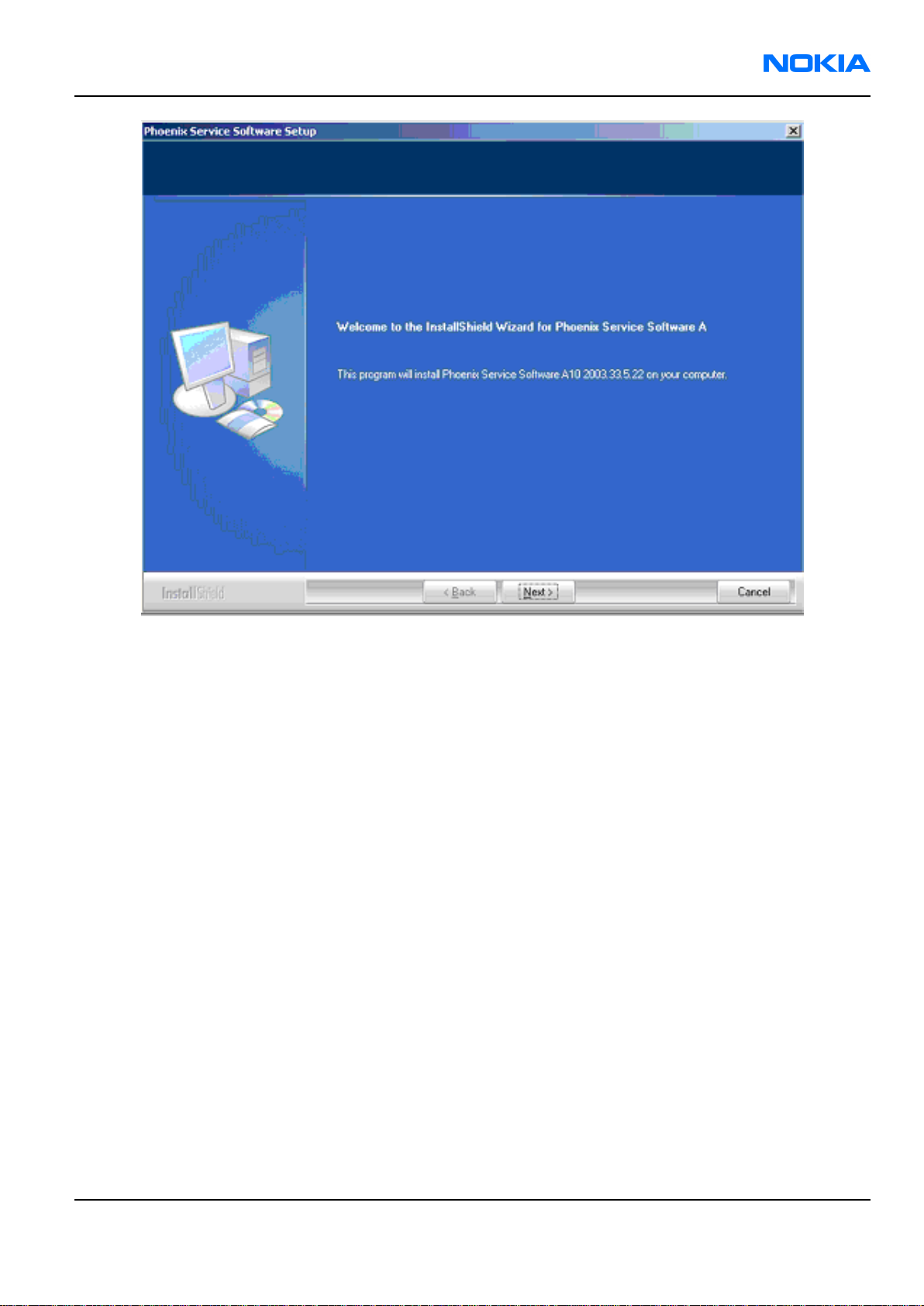
1. Run the phoenix_service_sw_a15_2004_24_7_55.exe to start installation. Install Shield will prepare.
Figure 2 Preparing setup
2. Click "Next" in Welcome dialog to continue.
Page 3–6 Company Confidential Issue 1
Copyright © 2004 Nokia. All Rights Reserved.
Page 49
RM-25
Phoenix installation Nokia Customer Care
3. Read the text carefully.
Figure 3 Welcome dialogue
Issue 1 Company Confidential Page 3–7
Copyright © 2004 Nokia. All Rights Reserved.
Page 50

RM-25
Nokia Customer Care Phoenix installation
Figure 4 Disclaimer text
4. Choose destination folder, it is recommended to use the default folder C:\ProgramFiles\Nokia\Phoenix.
Choose “Next” to continue. You may choose another location by selecting “Browse” (not recommended).
Page 3–8 Company Confidential Issue 1
Copyright © 2004 Nokia. All Rights Reserved.
Page 51

RM-25
Phoenix installation Nokia Customer Care
Figure 5 Destination folder
5. Setup copies the components, progress of the setup is shown. Please wait.
Issue 1 Company Confidential Page 3–9
Copyright © 2004 Nokia. All Rights Reserved.
Page 52

RM-25
Nokia Customer Care Phoenix installation
Figure 6 Installation status 1
6. Drivers will be installed and updated, please wait. The process may take several minutes to complete.
Page 3–10 Company Confidential Issue 1
Copyright © 2004 Nokia. All Rights Reserved.
Page 53

RM-25
Phoenix installation Nokia Customer Care
Figure 7 Installation status 2
If the operating system does not require rebooting (Windows 2000, XP) the PC components are registered
right away.
Issue 1 Company Confidential Page 3–11
Copyright © 2004 Nokia. All Rights Reserved.
Page 54

RM-25
Nokia Customer Care Phoenix installation
Figure 8 Registering components 1
If the operating system used requires restarting your computer ( Windows 98, SE, ME ) the Install Shield
Wizard will tell you about it. Select "Yes..." to reboot the PC immediatelly and "No..." to reboot the PC manually
afterwards.
Page 3–12 Company Confidential Issue 1
Copyright © 2004 Nokia. All Rights Reserved.
Page 55

RM-25
Phoenix installation Nokia Customer Care
Figure 9 Restart computer
After the reboot components are registered and Phoenix is ready for use. Note that Phoenix doesn't work,
if components are not registered.
Figure 10 Registering components 2
7. Click "Finish" to finalize. Phoenix is ready for use.
Issue 1 Company Confidential Page 3–13
Copyright © 2004 Nokia. All Rights Reserved.
Page 56

RM-25
Nokia Customer Care Phoenix installation
Figure 11 Finish installation
Next action
Now the installation of Phoenix Service SW is ready and it can be used after:
• Installing Phone model specific Phone Data Package for Phoenix
• Configuring users and connections
• FLS-4S can be used right away
• FPS-8* can be used after updating Flash Update Package files for it
Phoenix update installation
If you already have the Phoenix Service SW installed on your computer, sooner or later there will be need to
update it when new versions are released.
Always use the latest available versions of both the Phoenix Service SW and the phone-specific Data Package.
Instructions can be found in phone model specific Technical Bulletins and Phone Data Package readme.txt files
(shown during installation).
To update the Phoenix you need to take exactly the same steps as when installing it for the first time:
• Download the installation package to your computer hard disk.
• Close all other programs.
• Run the application file (for example, phoenix_service_sw_a15_2004_24_7_55.exe).
• New version of Phoenix will be installed.
• Driver versions will be checked and updated.
When you update the Phoenix from old to new version (for example, a14_2004_16_4_47 to a15_2004_24_7_55),
the update will take place automatically without uninstallation.
Page 3–14 Company Confidential Issue 1
Copyright © 2004 Nokia. All Rights Reserved.
Page 57

RM-25
Phoenix installation Nokia Customer Care
If you try to update the Phoenix with the same version that you already have (for example, a15_2004_24_7_55
to a15_2004_24_7_55) you are asked if you want to uninstall the version of Phoenix you have on your PC. In this
case you can choose between total uninstallation and repair just like when you choose to uninstall Phoenix
service software from the Windows Control panel.
If you try to install an older version (for example, downgrade from a15_2004_24_7_55 to a14_2004_16_4_47),
installation will be interrupted.
Figure 12 Installation interrupted
Always follow the instructions on the screen.
Uninstalling Phoenix
Context
Uninstallation can be done manually from Windows Control Panel - Add/Remove Programs.
Steps
1. Choose “Phoenix Service Software” and click "Add/Remove". Choose “Remove” to uninstall Phoenix.
Issue 1 Company Confidential Page 3–15
Copyright © 2004 Nokia. All Rights Reserved.
Page 58

RM-25
Nokia Customer Care Phoenix installation
Progress of the uninstallation is shown.
Figure 13 Remove program
Page 3–16 Company Confidential Issue 1
Copyright © 2004 Nokia. All Rights Reserved.
Page 59

RM-25
Phoenix installation Nokia Customer Care
Figure 14 Uninstallation status
2. If the operating system does not require rebooting, select “Finish” to complete.
Issue 1 Company Confidential Page 3–17
Copyright © 2004 Nokia. All Rights Reserved.
Page 60

RM-25
Nokia Customer Care Phoenix installation
Figure 15 Finish uninstallation
If the operating system used requires rebooting, Install Shield Wizard will tell you about it. Select "Yes..." to
reboot the PC immediately and "No..." to reboot the PC manually afterwards.
Page 3–18 Company Confidential Issue 1
Copyright © 2004 Nokia. All Rights Reserved.
Page 61

RM-25
Phoenix installation Nokia Customer Care
Figure 16 Restart computer
Repairing Phoenix installation
Context
If you experience any problems with service software or suspect that files have been lost, you can use the repair
function before completely reinstalling Phoenix. Note that the original installation package (for example,
phoenix_service_sw_a15_2004_24_7_55.exe) must be found on your PC when you run the repair setup.
Steps
1. Open Windows Control Panel -> Add/Remove Programs.
2. Select Phoenix Service Software and click Add/Remove.
3. In the following view, choose Repair.
Issue 1 Company Confidential Page 3–19
Copyright © 2004 Nokia. All Rights Reserved.
Page 62

RM-25
Nokia Customer Care Phoenix installation
Figure 17 Repair program
Phoenix will reinstall components and register them, procedure is the same as in update installation.
4. Click Finish to complete.
Page 3–20 Company Confidential Issue 1
Copyright © 2004 Nokia. All Rights Reserved.
Page 63

RM-25
Phoenix installation Nokia Customer Care
Figure 18 Finish repair installation
Phoenix service software data package overview
Each product has its own data package (DP). The product data package contains all product-specific data files
to make the Phoenix Service Software and tools usable with a certain phone model:
• Product software Binary files
• Files for type label printing
• Validation file for the Faultlog repair data reporting system
• All product-specific configuration files for Phoenix software components
Data files are stored under C:\Program Files\Nokia\Phoenix (default).
Installing Phoenix data package
Before you begin
• Product Data Package contains all product-specific data to make the Phoenix Service Software and tools
usable with a certain phone model.
• Check that the dongle is attached to the parallel port of your computer.
• Install Phoenix Service SW.
• Download the installation package (for example, RM-25_dp_EA_v_1_0.exe) to your computer (for example, in
C:\TEMP).
• Close all other programs.
• Run the application file (for example, RM-25_dp_EA_ v_1_0.exe) and follow the instructions on the screen.
If you already have the Phoenix Service SW installed on your computer, you will need to update it when a new
version is released.
Issue 1 Company Confidential Page 3–21
Copyright © 2004 Nokia. All Rights Reserved.
Page 64

RM-25
Nokia Customer Care Phoenix installation
Note: Very often the Phoenix Service SW and the phone-specific data package for Phoenix come in
pairs, meaning that a certain version of Phoenix can only be used with a certain version of the data
package. Always use the latest available versions of both. Instructions can be found in phone model
specific Technical Bulletins and readme.txt files of the data packages.
Steps
1. Run the RM-25_dp_EA_ v_1_0.exe to start installation.
2. Choose Next, and the files needed for installation will be extracted. Please wait.
Figure 19 Extracting files
3. Choose Next to continue.
Page 3–22 Company Confidential Issue 1
Copyright © 2004 Nokia. All Rights Reserved.
Page 65

RM-25
Phoenix installation Nokia Customer Care
Figure 20 Continue data package installation
In this view, you can see the contents of the data package. Read the text carefully. There should be
information about the Phoenix version needed with this data package.
Issue 1 Company Confidential Page 3–23
Copyright © 2004 Nokia. All Rights Reserved.
Page 66

RM-25
Nokia Customer Care Phoenix installation
Figure 21 Data package setup information
Choose Next.
4. Confirm location and choose Next to continue.
Page 3–24 Company Confidential Issue 1
Copyright © 2004 Nokia. All Rights Reserved.
Page 67

RM-25
Phoenix installation Nokia Customer Care
Figure 22 Data package destination folder
The install shield checks where the Phoenix application is installed and the directory is shown.
Choose Next to continue.
5. Choose Next to start copying the files.
Issue 1 Company Confidential Page 3–25
Copyright © 2004 Nokia. All Rights Reserved.
Page 68

RM-25
Nokia Customer Care Phoenix installation
Figure 23 Start copying files
Phone model specific files will be installed. Please wait.
Page 3–26 Company Confidential Issue 1
Copyright © 2004 Nokia. All Rights Reserved.
Page 69

RM-25
Phoenix installation Nokia Customer Care
Figure 24 Data package installation status
6. Click Finish to complete the installation.
Issue 1 Company Confidential Page 3–27
Copyright © 2004 Nokia. All Rights Reserved.
Page 70

RM-25
Nokia Customer Care Phoenix installation
Figure 25 Finish data package installation
You now have all phone model specific files installed in your Phoenix Service SW.
Next action
Now Phoenix can be used to for example flash phones and print type labels after:
• Configuring users
• Managing connections
• FLS-4S can be used right away
• FPS-8* can be used after updating Flash Update Package files for it.
Uninstalling Phoenix data package
Context
If you try to install the same version of Phoenix data package that you already have, you are asked if you want
to uninstall the version you have on your PC. Older versions of data packages don´t need to be uninstalled unless
instructions to do so are given in the readme.txt of the data package and bulletins concerning the release.
Please read all related documents carefully.
Steps
1. Answer OK to uninstall, Cancel if you don’t want to uninstall.
Page 3–28 Company Confidential Issue 1
Copyright © 2004 Nokia. All Rights Reserved.
Page 71

RM-25
Phoenix installation Nokia Customer Care
Figure 26 Uninstalling Phoenix data package
2. Once the previously installed data package is uninstalled, choose Finish.
Figure 27 Finish data package uninstallation
Alternative steps
• Uninstallation can also be done manually from Windows Control Panel / Add/Remove Programs / ”RM-25
Phone Data Package”.
Next action
Run the installation package again to continue installation from the beginning.
Issue 1 Company Confidential Page 3–29
Copyright © 2004 Nokia. All Rights Reserved.
Page 72

RM-25
Nokia Customer Care Phoenix installation
(This page left intentionally blank.)
Page 3–30 Company Confidential Issue 1
Copyright © 2004 Nokia. All Rights Reserved.
Page 73

Nokia Customer Care
4 — Phoenix instructions
Issue 1 Company Confidential Page 4–1
Copyright © 2004 Nokia. All Rights Reserved.
Page 74

RM-25
Nokia Customer Care Phoenix instructions
(This page left intentionally blank.)
Page 4–2 Company Confidential Issue 1
Copyright © 2004 Nokia. All Rights Reserved.
Page 75

RM-25
Phoenix instructions Nokia Customer Care
Table of Contents
Configuring users in Phoenix.....................................................................................................................................................4–5
Managing connections in Phoenix...........................................................................................................................................4–6
Installing Flash support files for FPS-8* and FLS-4*.........................................................................................................4–10
Updating the FPS-8 Flash prommer SW................................................................................................................................4–14
Activating FPS-8............................................................................................................................................................................4–17
Deactivating FPS-8.......................................................................................................................................................................4–18
Installing SW needed for the JBV-1 docking station SW update..................................................................................4–19
List of Figures
Figure 1 Login...................................................................................................................................................................................4–5
Figure 2 Add information for new user 1................................................................................................................................4–5
Figure 3 Add information for new user 2................................................................................................................................4–6
Figure 4 Login, user configured..................................................................................................................................................4–6
Figure 5 Phoenix icon....................................................................................................................................................................4–6
Figure 6 Manage connections.....................................................................................................................................................4–7
Figure 7 Connections list...............................................................................................................................................................4–7
Figure 8 Select mode: Manual.....................................................................................................................................................4–8
Figure 9 FLS virtual port icon.......................................................................................................................................................4–8
Figure 10 Connections list............................................................................................................................................................4–9
Figure 11 Connection information............................................................................................................................................4–9
Figure 12 Scan product..................................................................................................................................................................4–9
Figure 13 Product support module information................................................................................................................4–10
Figure 14 Flash update welcome dialogue..........................................................................................................................4–11
Figure 15 Uninstall flash update package.............................................................................................................................4–11
Figure 16 Flash installation interrupted................................................................................................................................4–11
Figure 17 Continue flash update..............................................................................................................................................4–12
Figure 18 Flash destination folder..........................................................................................................................................4–12
Figure 19 Flash installation status..........................................................................................................................................4–13
Figure 20 Finish flash update....................................................................................................................................................4–14
Figure 21 Phoenix icon...............................................................................................................................................................4–14
Figure 22 FPS-8 maintenance...................................................................................................................................................4–14
Figure 23 Prommer SW update................................................................................................................................................4–15
Figure 24 Prommer SW update done.....................................................................................................................................4–15
Figure 25 FPS-8 info window....................................................................................................................................................4–16
Figure 26 Flash directory window...........................................................................................................................................4–16
Figure 27 FPS-8 maintenance...................................................................................................................................................4–17
Figure 28 FPS-8 info window....................................................................................................................................................4–17
Figure 29 Box activation.............................................................................................................................................................4–18
Figure 30 Deactivation warning..............................................................................................................................................4–19
Figure 31 Extracting JBV-1 update files.................................................................................................................................4–20
Figure 32 JBV-1 update information.......................................................................................................................................4–20
Figure 33 JBV-1 update destination folder...........................................................................................................................4–20
Figure 34 Select installation: Full.............................................................................................................................................4–21
Figure 35 Select program folder..............................................................................................................................................4–21
Figure 36 Finish JBV-1 update installation...........................................................................................................................4–22
Figure 37 Checking JBV-1 SW version.....................................................................................................................................4–22
Figure 38 JBV-1 update directory window...........................................................................................................................4–23
Figure 39 JBV-1 SW update done.............................................................................................................................................4–23
Figure 40 JBV-1 SW status..........................................................................................................................................................4–23
Issue 1 Company Confidential Page 4–3
Copyright © 2004 Nokia. All Rights Reserved.
Page 76

RM-25
Nokia Customer Care Phoenix instructions
(This page left intentionally blank.)
Page 4–4 Company Confidential Issue 1
Copyright © 2004 Nokia. All Rights Reserved.
Page 77

RM-25
Phoenix instructions Nokia Customer Care
Configuring users in Phoenix
Steps
1. Start Phoenix Service SW and log in. If your user ID is already configured, choose it from the dropdown list
and click OK. To add a new user or edit existing ones click Maintain.
Figure 1 Login
2. Choose New to add information for a new user.
Figure 2 Add information for new user 1
3. Type in your name and Initials and click OK.
Issue 1 Company Confidential Page 4–5
Copyright © 2004 Nokia. All Rights Reserved.
Page 78

RM-25
Nokia Customer Care Phoenix instructions
Figure 3 Add information for new user 2
User has now been created.
4. Click OK.
You are now able to login with this username.
5. Click OK.
Figure 4 Login, user configured
Managing connections in Phoenix
Steps
1. Start Phoenix Service SW and Login.
Figure 5 Phoenix icon
2. Choose “Manage Connections” From “File” – Menu
Page 4–6 Company Confidential Issue 1
Copyright © 2004 Nokia. All Rights Reserved.
Page 79

RM-25
Phoenix instructions Nokia Customer Care
Figure 6 Manage connections
Existing connections can be selected, edited, deleted and new ones created by using this dialog.
Figure 7 Connections list
3. A connection can be created either manually or by using a Connection Wizard. To add new connection, choose
“Add” and select if you want to create it manually or by using the Wizard.
In the next dialogs you will be asked to select some settings for the connection. If you use the Wizard, connect
the tools and a phone to your PC and the wizard will automatically try to configure the correct connection.
4. Select Manual mode. Choose Next to continue.
Issue 1 Company Confidential Page 4–7
Copyright © 2004 Nokia. All Rights Reserved.
Page 80

RM-25
Nokia Customer Care Phoenix instructions
Figure 8 Select mode: Manual
i For FLS-4S POS Flash Device, choose following connection settings:
• Media: FBUS
• COM Port: Virtual COM Port used by FLS-4 Please
Note: ALWAYS check this. Go to Windows -> Control Panel -> FLS Virtual Port -> Configuration.
Figure 9 FLS virtual port icon
ii For FPS-8 Flash Prommer, choose following connection settings:
• Media: FPS-8
• Port Num: COM Port where FPS-8 is connected
• COMBOX_DEF_MEDIA: FBUS
5. Click Finish to complete.
6. Activate the connection you want to use by clicking it and use up/down arrows to move it on top of the list.
Choose “Apply”. The connection is now selected and can be used after closing the “Manage Connections”
window.
Page 4–8 Company Confidential Issue 1
Copyright © 2004 Nokia. All Rights Reserved.
Page 81

RM-25
Phoenix instructions Nokia Customer Care
Figure 10 Connections list
Selected connection will be shown on the right hand bottom corner of the screen.
Figure 11 Connection information
7. To use the selected connection, connect the phone to Phoenix with correct service tools, make sure that it
is switched on and select Scan Product.
Figure 12 Scan product
When a product is found, Phoenix will load product support. Name of the loaded product support module
and its version information will be shown on the bottom of the screen.
Issue 1 Company Confidential Page 4–9
Copyright © 2004 Nokia. All Rights Reserved.
Page 82

RM-25
Nokia Customer Care Phoenix instructions
Figure 13 Product support module information
Installing Flash support files for FPS-8* and FLS-4*
Before you begin
Note: Only separate installation package.
• Install Phoenix Service SW.
• Install phone model specific Data Package for Phoenix.
• The flash support files are delivered in the same installation package with Phoenix data packages or newer
Phoenix packages beginning from September 2003.
• Normally it is enough to install the Phoenix and phone data package only because the Phoenix installation
always includes the latest flash update package files for FLS-4S/FPS-8*.
• Separate installation package for flash support files is available, and the files can be updated according to
this instruction if updates appear between Phoenix/data package releases.
Context
If you are not using a separate installation package, you can skip this section and continue with FPS-8 Flash
prommer SW update after installing a new Phone Data package.
Steps
1. Start by double clicking flash_update_03_13_001.exe. Installation begins.
Page 4–10 Company Confidential Issue 1
Copyright © 2004 Nokia. All Rights Reserved.
Page 83

RM-25
Phoenix instructions Nokia Customer Care
Figure 14 Flash update welcome dialogue
2. If the same version of Flash Update package already exists, and you want to reinstall it, the previous package
is first uninstalled. Restart installation again after that.
Figure 15 Uninstall flash update package
If you try to downgrade the existing version to older ones, the setup will be aborted. If you really want to
downgrade, uninstall newer files manually from Control Panel and then rerun the installation again.
Figure 16 Flash installation interrupted
If an older version exists on your PC and it needs to be updated, choose Next to continue installation.
Issue 1 Company Confidential Page 4–11
Copyright © 2004 Nokia. All Rights Reserved.
Page 84
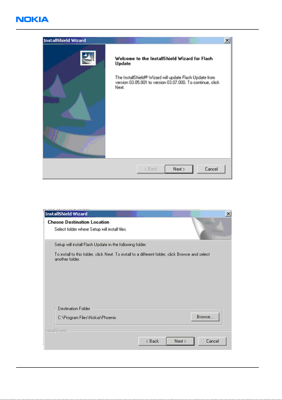
RM-25
Nokia Customer Care Phoenix instructions
Figure 17 Continue flash update
3. It is highly recommended to install the files to the default destination folder C:\Program Files\Nokia\Phoenix.
Choose “Next” to continue.
Figure 18 Flash destination folder
Page 4–12 Company Confidential Issue 1
Copyright © 2004 Nokia. All Rights Reserved.
Page 85

RM-25
Phoenix instructions Nokia Customer Care
When installing the flash update files for the first time you may choose another location by selecting Browse.
This is not recommended.
4. Installation will continue.
Figure 19 Flash installation status
5. Choose Finish to complete procedure.
Issue 1 Company Confidential Page 4–13
Copyright © 2004 Nokia. All Rights Reserved.
Page 86

RM-25
Nokia Customer Care Phoenix instructions
Figure 20 Finish flash update
Next action
FLS-4 can be used right after Flash Update Package is installed.
FPS-8* flash prommer must be updated using Phoenix!
Updating the FPS-8 Flash prommer SW
Steps
1. Start Phoenix Service Software and login, manage connection correctly for the FPS-8* flash prommer.
Figure 21 Phoenix icon
2. Select ”FPS-8 maintenance” from ”Flashing” menu.
Figure 22 FPS-8 maintenance
Page 4–14 Company Confidential Issue 1
Copyright © 2004 Nokia. All Rights Reserved.
Page 87

RM-25
Phoenix instructions Nokia Customer Care
3. When new FPS-8 flash update package is installed to computer you will be asked to update the files to your
FPS-8 Prommer. Select ”Yes” to update files.
Figure 23 Prommer SW update
4. Update procedure takes a couple of minutes, please wait until you are notified that update has been
successful. Click “OK” to close “FPS8 Maintenance” window.
Figure 24 Prommer SW update done
View after successful prommer software update:
Issue 1 Company Confidential Page 4–15
Copyright © 2004 Nokia. All Rights Reserved.
Page 88

RM-25
Nokia Customer Care Phoenix instructions
Figure 25 FPS-8 info window
5. FPS-8 SW can also be updated by pressing ”Update” button and selecting appropriate fps8upd.ini file Under
C:\Program Files\Nokia\Phoenix\Flash - directory
Figure 26 Flash directory window
6. All files can be loaded separately to FPS-8. To do this, just press right mouse button in ”Flash box files”
window and select filetype to be loaded.
More information and help can be found from “Help” dialog.
Page 4–16 Company Confidential Issue 1
Copyright © 2004 Nokia. All Rights Reserved.
Page 89

RM-25
Phoenix instructions Nokia Customer Care
Activating FPS-8
Context
Before FPS-8 can be successfully used for phone programming, it must first be activated. Fill in first the “FPS-8
activation request” sheet, in the FPS-8 sales package and follow the instructions in the sheet.
When activation file is received (for example, 00000.in), copy it to C:\ProgramFiles\Nokia\Phoenix\BoxActivation
directory on your computer (this directory is created when Phoenix is installed).
Steps
1. Start Phoenix Service Software.
2. Select ”FPS-8 maintenance” from ”Flashing” menu.
Figure 27 FPS-8 maintenance
3. Select “Activate” in the “FPS8 Maintenance” window. The box will be activated after you click “Activate”.
Figure 28 FPS-8 info window
Issue 1 Company Confidential Page 4–17
Copyright © 2004 Nokia. All Rights Reserved.
Page 90

RM-25
Nokia Customer Care Phoenix instructions
Browse to find the activation file in case you saved it to some other directory on your PC.
4. Click “Open” to activate the box.
Figure 29 Box activation
5. Turn FPS-8 power off and on to complete activation.
Deactivating FPS-8
Context
If there is a need to send the FPS-8 box for repair for instance, the box must first be deactivated.
Steps
1. Start Phoenix Service Software.
2. Select ”FPS-8 maintenance” from ”Flashing” menu as when activating prommer or updating SW.
3. Select “Deactivate” in the “FPS-8 Maintenance” window.
4. Confirm Deactivation by choosing “Yes”. The box will be deactivated.
Page 4–18 Company Confidential Issue 1
Copyright © 2004 Nokia. All Rights Reserved.
Page 91

RM-25
Phoenix instructions Nokia Customer Care
Figure 30 Deactivation warning
5. Turn FPS-8 power off and on to complete deactivation.
Installing SW needed for the JBV-1 docking station SW update
Before you begin
The JBV-1 Docking Station contains Software (Firmware) which can be updated. You need the following
equipment to be able to update JBV-1 software:
• PC with USB connection
• Operating System supporting USB (Not Win 95 or NT)
• USB Cable (can be purchased from shops or suppliers providing PC hardware and accessories)
• JBV-1 Docking Station
• External Power Supply 11-16V
Before installation:
• Download Jbv1_18_update.zip file to your computer (eg C:\TEMP) from your download web site.
• Close all other programs.
• Follow instructions on the screen.
Context
The JBV-1 Docking Station is a common tool for all DCT-4 generation products. In order to make the JBV-1 usable
with different phone models, a phone-specific Docking Station Adapter is used for different service functions.
Steps
1. Note: DO NOT CONNECT THE USB CABLE/JBV-1 TO YOUR COMPUTER YET!
Run Jbv1_18_update.zip file and start SW Installation by double clicking Setup.exe. Files needed for
JBV-1 Package setup program will be extracted.
Issue 1 Company Confidential Page 4–19
Copyright © 2004 Nokia. All Rights Reserved.
Page 92

RM-25
Nokia Customer Care Phoenix instructions
Figure 31 Extracting JBV-1 update files
2. Installation begins. Read the information shown and choose Next to continue.
Figure 32 JBV-1 update information
3. Use the suggested destination folder where JBV-1 SW Package will be installed and choose Next to continue.
Figure 33 JBV-1 update destination folder
4. Select Full installation and choose Next to continue.
Page 4–20 Company Confidential Issue 1
Copyright © 2004 Nokia. All Rights Reserved.
Page 93

RM-25
Phoenix instructions Nokia Customer Care
Figure 34 Select installation: Full
5. Program Folder will be created and software files installed. Choose Next to continue.
Figure 35 Select program folder
6. After successful installation, click Finish to complete.
Issue 1 Company Confidential Page 4–21
Copyright © 2004 Nokia. All Rights Reserved.
Page 94

RM-25
Nokia Customer Care Phoenix instructions
Figure 36 Finish JBV-1 update installation
7. Connect the USB cable/JBV-1 to your computer. Connect power to JBV-1 (11-16V DC) from external power
supply, then connect USB Cable between JBV-1 USB connector and PC.
8. Install or update the JBV-1 USB drivers which are delivered with the JBV-1 SW installation package. They
can be found in folder:
C:\Program Files\Nokia\ JBV-1 Firmware Update\JBV-1USB driver
• If there is no previously installed JBV-1 Firmware update package installed on your computer, Windows
will detect connected USB cable and detect drivers for new HW. You will be prompted about this, please
follow the instructions and allow Windows to search and install the best drivers available.
• If there is a previously installed JBV-1 Firmware update package (v.17 or older) on your computer, please
update the JBV-1 USB driver. Please see the readme.txt file under C:\Program Files\Nokia\JBV-1 Firmware
Update\JBV-1USB driver folder for instructions on how to update the JBV-1 USB Driver.
After you have installed or updated the JBV-1 USB driver, the actual JBV-1 SW update can begin.
9. Go to folder C:\Program Files\Nokia\JBV-1 Firmware Update\JBV-1 Firmware Update and start JBV-1 Update
SW by double clicking fwup.exe.
JBV-1 Firmware update starts and shows current status of the JBV-1 connected. If firmware version read
from your JBV-1 is not the latest one available (v.17 or older), it needs to be updated to version 18 by
choosing Update Firmware.
10. If you simply want to check the SW version, choose Refresh Status.
Figure 37 Checking JBV-1 SW version
11. To update your JBV-1 to a new version (v.18) choose file JBV1v18.CDE and “Open”. Please wait, it takes a
while until you can hear a “click” from the JBV-1.
The older SW file JBV1v17.CDE is visible in this view only if the previous JBV-1 SW package has been installed
on your computer.
Page 4–22 Company Confidential Issue 1
Copyright © 2004 Nokia. All Rights Reserved.
Page 95

RM-25
Phoenix instructions Nokia Customer Care
Figure 38 JBV-1 update directory window
12. After a successful update, current JBV-1 status will be shown after you click OK.
Figure 39 JBV-1 SW update done
Figure 40 JBV-1 SW status
You have now updated the software of your JBV-1 docking station and it is ready for use.
Next action
If you have several docking stations you need to update, disconnect the power and USB cables from the previous
one and connect them to the next docking station. Click Refresh Status to see the current SW version and then
Update Firmware to update the SW.
After you have updated all docking stations, close the “JBV-1 Firmware Update” dialogue
Issue 1 Company Confidential Page 4–23
Copyright © 2004 Nokia. All Rights Reserved.
Page 96

RM-25
Nokia Customer Care Phoenix instructions
(This page left intentionally blank.)
Page 4–24 Company Confidential Issue 1
Copyright © 2004 Nokia. All Rights Reserved.
Page 97

Nokia Customer Care
5 — Phoenix concepts
Issue 1 Company Confidential Page 5–1
Copyright © 2004 Nokia. All Rights Reserved.
Page 98

RM-25
Nokia Customer Care Phoenix concepts
(This page left intentionally blank.)
Page 5–2 Company Confidential Issue 1
Copyright © 2004 Nokia. All Rights Reserved.
Page 99

RM-25
Phoenix concepts Nokia Customer Care
Table of Contents
Flash concept...................................................................................................................................................................................5–5
POS flash concept...........................................................................................................................................................................5–6
JBV-1 flash concept........................................................................................................................................................................5–6
Module jig flash concept..............................................................................................................................................................5–7
Module jig service concept..........................................................................................................................................................5–8
JBV-1 service concept....................................................................................................................................................................5–9
List of Figures
Figure 1 Flash concept...................................................................................................................................................................5–5
Figure 2 POS flash concept...........................................................................................................................................................5–6
Figure 3 JBV-1 flash concept........................................................................................................................................................5–6
Figure 4 Module jig flash concept..............................................................................................................................................5–7
Figure 5 Module jig service concept..........................................................................................................................................5–8
Figure 6 JBV-1 service concept....................................................................................................................................................5–9
Issue 1 Company Confidential Page 5–3
Copyright © 2004 Nokia. All Rights Reserved.
Page 100

RM-25
Nokia Customer Care Phoenix concepts
(This page left intentionally blank.)
Page 5–4 Company Confidential Issue 1
Copyright © 2004 Nokia. All Rights Reserved.
 Loading...