

Nokia 32XX, 81XX, 88XX, 61XX, 21XX User Manual
...
Nokia
NetMonitor
Manual
Version 0.95
11.11.2002
Document keeper : nobbi (nobbi@nobbi.com)
Base document : Flipo (flipo@gyral.com)
PDF + Enhancements to base document : nobbi
Graphics : nobbi

Phone Models and Software versions
Notes for 21xx / 31xx / 81xx phones
The older phones netmonitor has some differences when compared with the one of newer models, but
this manual can be used as a guide, because the overall working method and the display contents are
very similar in most cases.
Notes for 51xx/61xx/62xx/71xx/88xx/91xx/32xx and other phones
This document covers the majority of pages from these phones netmonitor. Some of them may have
little differences, like missing/additional pages, different info, etc.
The 51xx and 61xx pages are almost identical, there are a few pages concerning multiband information
in 6150 which are different in the singleband phones, and the xx90 pages are partially different, because
of some special things in GSM1900.
The 32xx has some more pages, which are not very well documented yet.
The 62xx and 71xx have a whole bunch of pages concerning W@P and the large internal flash memory.
These are not documented yet. If you have any clue about theses pages, send me a mail.
The 91xx pages are almost identical to the 6110 ones, with few additional pages.
The goal right now is to make an accessible manual, that will get better over the time. Please contribute
with all the info that you find relevant. Please note that this manual does only deal with pages which are
of known content, so if a page is not mentioned here, I have most likely no knowledge about the
meaning of the page.
Used Information Sources :
[ 1 ] Netmonitor description (RD843.txt) from Nokia Mobile Phones
[ 2 ] Marcin Wiaceks homepage (http://marcin-wiacek.topnet.pl/
)
[ 3 ] Researches from Nobbi & various other people
2

Menu Modes
There are three Menu Display modes:
- the execute mode
- the data display mode
- the help mode
Different modes are marked in this manual as follows:
************** ++++++++++++++ ##############
* * + + # #
* Execute * +Data display+ # Help #
* Mode * + Mode + # Mode #
* * + + # #
************** ++++++++++++++ ##############
The execute mode is entered from the menu by selecting a menu directly with his number. If the test
index entered pertains to a test that resets a timer (test 80) for example, then the timer is reset as soon
as the OK button has been pressed in the menu, and the data display mode takes over. In other words,
the execute mode is of the one-shot type. To run another test in the execute mode, the Field Test
Display menu must be reactivated.
So, be very careful when jumping to a netmonitor page directly from the menu selection. You may
activate the execute mode incidentally, causing your phone to behave not as expected.
The data display mode is active by default when the Netmonitor is active. During data display mode, the
field test data is visible on the main display.
During help mode, one screen of instructions is shown for each test to make it easier to identify the test
in question. A long press of the asterisk (*) is used to toggle between these two modes.
The arrow keys (^,v) offer an easy way to switch to another test without using the menu. However,
nothing will be executed or set on although such tests would be passed. This is to prevent the user from
accidentally clearing any valuable data. The help mode is also a non-execute mode. Display numbers
have been selected in such way that no 5-terminated test number is an execute display.
Reserving SIM phonebook locations
When using a phone with enabled field test displays, it is highly recommended to put some default data
into the SIM phonebook locations that are used by some field test displays. Especially Test 17 (BTS
TEST) may give some confusing results if SIM phonebook location 33 is not correctly configured.
Additionally, this prevents accidental storing of phone numbers and names into such locations.
Displays 52 and 53 may also write some data to the SIM phonebook locations 35 and 36.
Location Default Data Used by Display #
31 65535 71
32 65535 72
33 0 17 (BTS TEST)
34,35,36 34,35,36 52, 53
Reserving SIM SCM locations is not necessary if the user is sure that he will never select these displays
using menu shortcut (which executes the display in question).
3

Table of contents
Phone Models and Software versions..................................................................................... 2
Notes for 21xx / 31xx / 81xx phones...................................................................... 2
Notes for 51xx/61xx/62xx/71xx/88xx/91xx/32xx and other phones....................... 2
Menu Modes............................................................................................................................ 3
Reserving SIM phonebook locations....................................................................................... 3
Table of contents .....................................................................................................................4
Basics: Channel numbers in GSM........................................................................................... 4
Display 1 – Serving cell info..................................................................................................... 5
Display 10 – Paging Repetition Period, TMSI, Location Update Timer, AFC and AGC ......... 9
Display 20 – Charging state................................................................................................... 12
Display 39 – Information about reasons for call clearing....................................................... 16
Display 40 – Reset handover counters.................................................................................. 17
Display 60 – Reset counters to zero...................................................................................... 21
Display 65 – SMS attempts counters .................................................................................... 23
Display 70 – Temporary counters of DSP............................................................................. 24
Display 80 – Reset and restart timers ................................................................................... 28
Display 100 (7110, 62XX) – Internal memory usage, overview ............................................ 31
Display 240 (no output) – Clear counters and start timers....................................................34
Basics: Channel numbers in GSM
GSM uses channel numbers between 0 and 1023. These frequency channels are allocated
by the different types of GSM as follows:
Type: Subtype: Channels:
GSM400 GSM450 259 .. 293
GSM700 GSM750 438 .. 511
GSM850 GSM850 128 .. 251
GSM900 PGSM 1 .. 124
GSM1800 GSM1800 512 .. 885
GSM1900 GSM1900 512 .. 810
GSM480 306 .. 340
EGSM 0 .. 124
975 .. 1023
GSM-R 0 .. 124
955 .. 1023
4

Display 1 – Serving cell info
++++++++++++++ ##############
+abbb ccc ddd+ #CH RxL TxPwr#
+ e ff g mmmm+ #TS TA RQ RLT#
+ nnn ppp+ # C1 C2 #
+ oooo + # CHT #
++++++++++++++ ##############
a H, if carrier numbers are scrolled when hopping is on. Otherwise ' '.
bbb When mobile is on a TCH :
ccc rx level in dBm, minus sign is not shown if <=-100
ddd tx power level. If transmitter is on, symbol * is shown in front of the
e Time Slot, range is 0 - 7
ff Timing advance, range is 0 – 63
g RX quality (sub), range is 0 - 7
mmmm Radio Link Timeout value. If value is negative, 0 is shown.
nnn value of the path loss criterium (C1). Range is -99 - 999.
oooo type of current channel (TCH := Traffic Channel):
ppp value of the cell reselection criterium (C2).
DCH carrier number in decimal.
When mobile is NOT on a TCH :
CH means carrier number in decimal.
If hopping is on, used channels are scrolled when display is updated.
power level value.
Maximum value is 64. When mobile is NOT on TCH then xx is shown.
THR0 : TCH HalfRate (HR) subchannel 0
THR1 : TCH HR subchannel 1
TFR : TCH FullRate (FR)
TEFR : TCH EnhancedFullRate
F144 : TCH FR data channel, speed 14.4 kbps
F96 : TCH FR data channel, speed 9.6 kbps
F72 : TCH FR data channel, speed 7.2 kbps
F48 : TCH FR data channel, speed 4.8 kbps
F24 : TCH FR data channel, speed 2.4 kbps
H480 : TCH HR data channel, speed 4.8 kbps, subch 0
H481 : TCH HR data channel, speed 4.8 kbps, subch 1
H240 : TCH HR data channel, speed 2.4 kbps, subch 0
H241 : TCH HR data channel, speed 2.4 kbps, subch 1
FA : TCH FR signalling only (FACCH) channel
FAH0 : TCH HR signalling only (FACCH) channel, subch 0
FAH1 : TCH HR signalling only (FACCH) channel, subch 1
SDCC : SDCCH
AGCH : Access Grant CHannel
CCCH : one of the Common Control CHannels
CBCH : CCCH and cell broadcast receiving on
BCCH : Broadcast Control CHannel
SEAR : SEARCHing for available networks
NSPS : MS is in ’No Service, Power Save’ state
Range is -99 to 999. If phone is phase 1 then C1 value is shown.
5
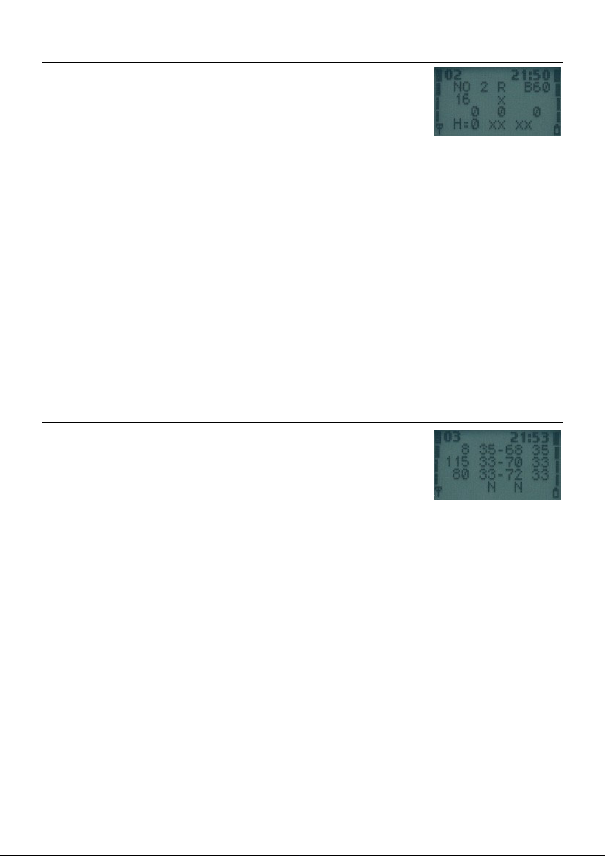
Display 2 – More info about serving cell
++++++++++++++ ##############
+ aa b c Bdd + #PM RAR Ro BC#
+ ee f + #RelR QLF #
+ ggg hh iii + #CRO TO PenT #
+ H=j mm nn + #H MAIO HSN #
++++++++++++++ ##############
aa paging mode
b maximum number of Random Access retransmission
c roaming indicator, values are 'R' or ' '.
Bdd Letter B and BSIC value, range is 0 - 63.
ee Reason of last call release (See Display 39, CC cause codes)
f RX quality (full), range is 0 - 7
ggg Cell reselection offset, range 0 - 126 dB.
hh Temporary offset, range 0 - 60 dB.
iii Penalty time, range 0 - 620 s.
j Hopping channel
mm mobile allocation index offset, MAIO
nn hopping sequence number, HSN
NO : normal paging
EX : extended paging
RO : paging reorganization
SB : same as before
[0 .. 63] * 2 dB. 'xxx' in dedicated mode.
[0 .. 7] * 10 dB. 70 dB means infinite time.
'xx' in dedicated mode.
[0 .. 31] * 20 s. 'xxx' in dedicated mode.
0 Single RF channel
1 RF hopping channel
Range: 00 to 63 / xx when H=0
Range: 00 to 63 / xx when H=0
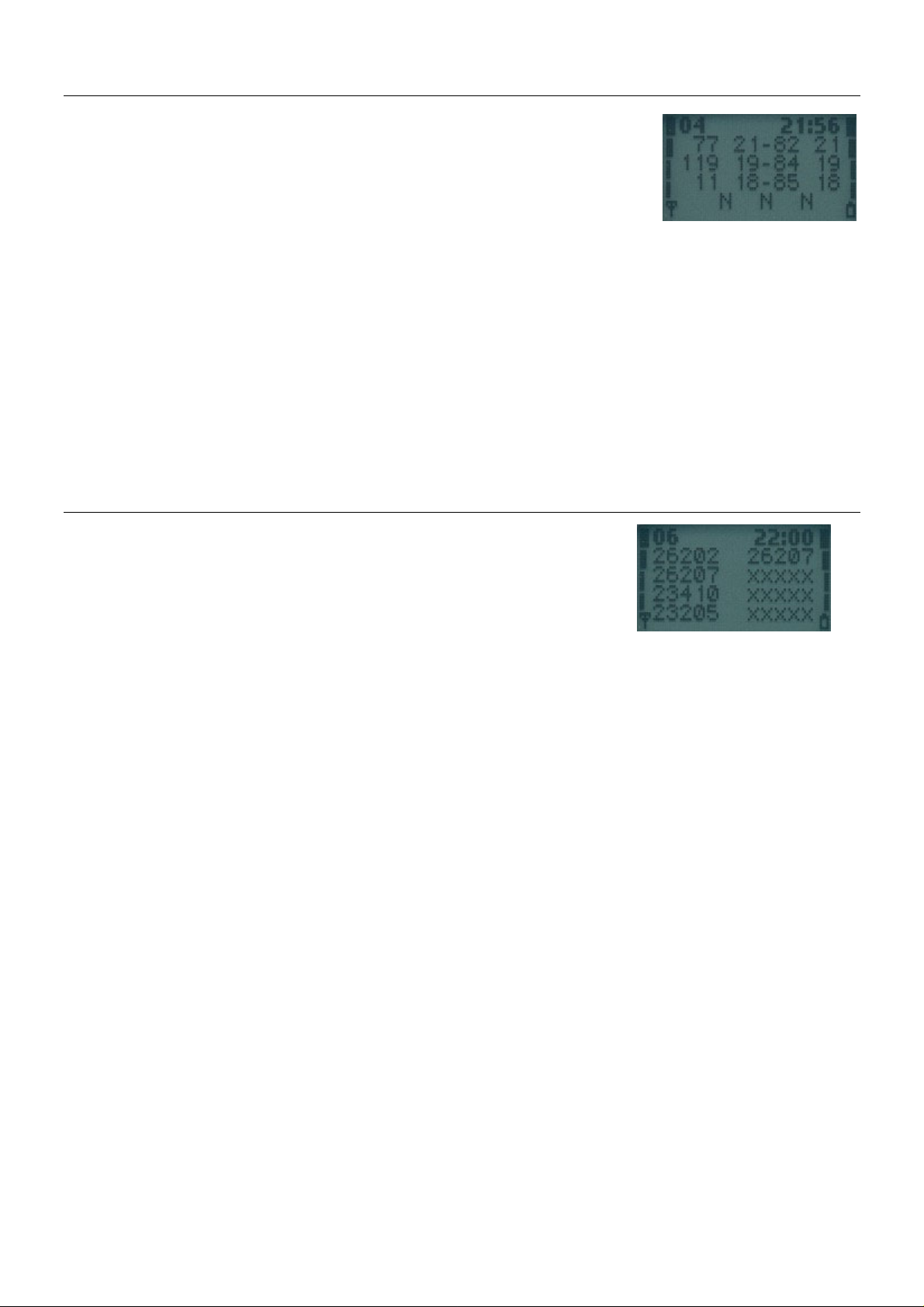
Display 3 – Serving cell, 1st and 2nd neighbour
++++++++++++++ ##############
+aaabbbcccddd+ #SCH C1 rx C2#
+aaabbbcccddd+ #1CH C1 rx C2#
+aaabbbcccddd+ #2CH C1 rx C2#
+ ef gh + # 1N 2N #
++++++++++++++ ##############
1. row: serving cell information
2. row: 1. neighbour information
3. row: 2. neighbour information
4. row, ef: 1. neighbour information
4. row, gh: 2. neighbour information
aaa carrier number in decimal, EGSM channels are displayed as Eaa
bbb idle mode : C1 value, range is -99 - 999
ccc RX level in dBm, minus sign is not shown if <=-100
ddd C2 value, range is -99 - 999
e,g F : cell is in a forbidden location area
f,h B : cell is barred
ded. Mode : 'B' and BSIC value
N : cell is normal priority
L : cell is low priority
6
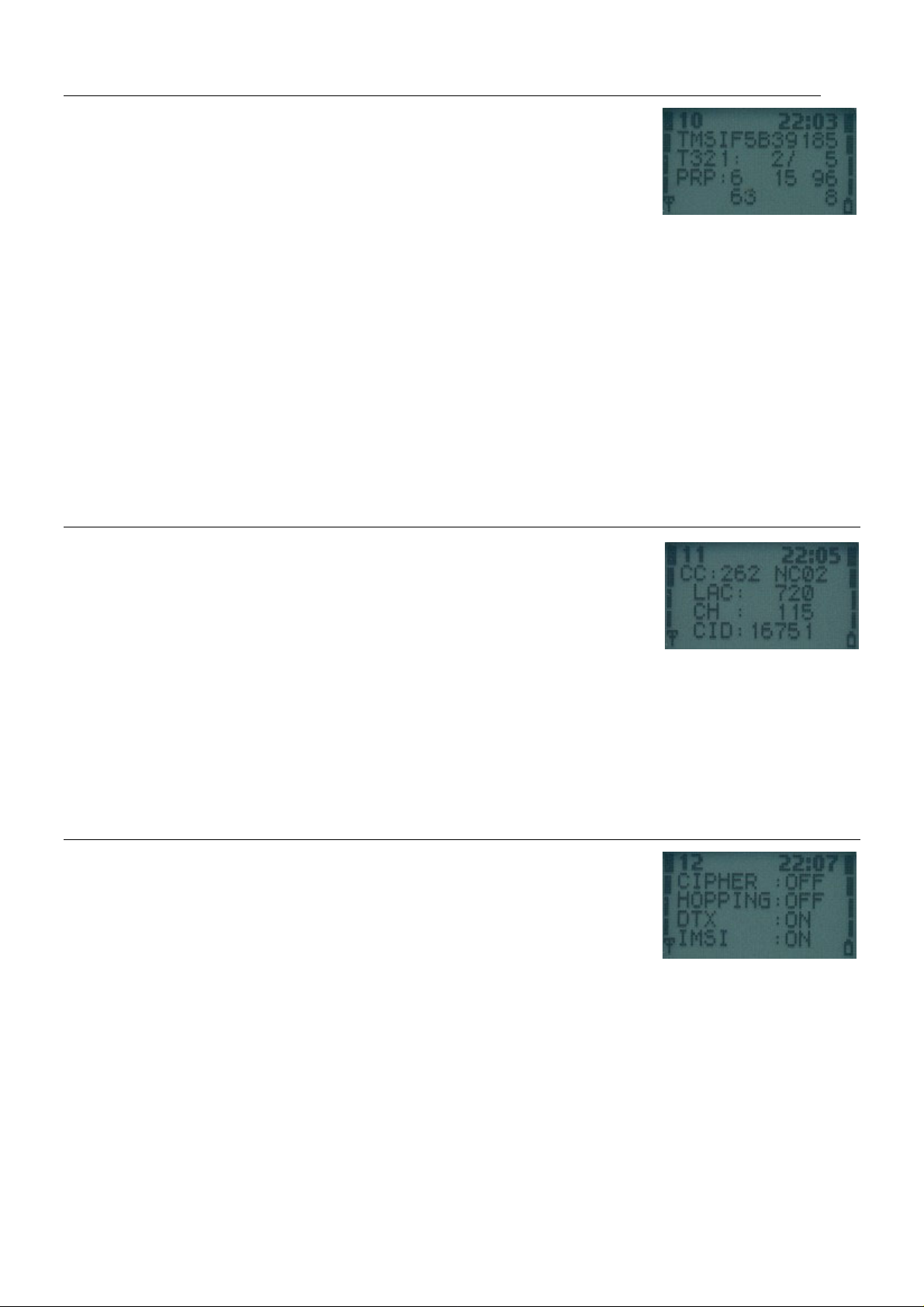
Display 4 & 5 – 3
++++++++++++++ ##############
+aaabbbcccddd+ #3CH C1 rx C2#
+aaabbbcccddd+ #4CH C1 rx C2#
+aaabbbcccddd+ #5CH C1 rx C2#
+ ef gh ij + # 3N 4N 5N #
++++++++++++++ ##############
1. row: 3./6. neighbour information
2. row: 4./7. neighbour information
3. row: 5./8. neighbour information
4. row, ef: 3./6. neighbour information
4. row, gh: 4./7. neighbour information
4. row, ij: 5./8. neighbour information
aaa carrier number in decimal, EGSM channels are displayed as Eaa
bbb idle mode : C1 value, range is -99 - 999
ccc rx level in dBm, minus sign is not shown if <=-100
ddd C2 value, range is -99 - 999
e,g,i F : cell is in a forbidden location area
f,h,j B : cell is barred
rd
ded. Mode : 'B' and BSIC value
N : cell is normal priority
L : cell is low priority
to 8th neighbour cell
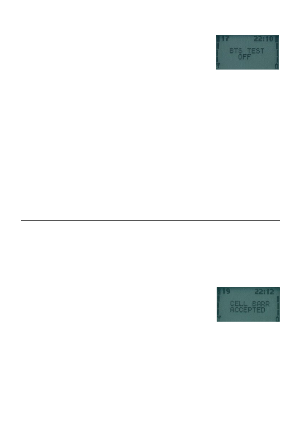
Display 6 – Network selection display
++++++++++++++ ##############
+aaabb aaabb+ #LReg 1_For#
+aaabb aaabb+ #1_Pre 2_For#
+aaabb aaabb+ #2_Pre 3_For#
+aaabb aaabb+ #3_Pre 4_For#
++++++++++++++ ##############
This display shows the last registered networks country code (MCC) and
network code (MNC) as well as the codes for four forbidden networks
and the first 3 preferred networks.
If a three-digit MNC is used (GSM1900), display looks different:
++++++++++++++
+aaabbbaaabbb+
+aaabbbaaabbb+
+aaabbbaaabbb+
+aaabbbaaabbb+
++++++++++++++
1. row: last registered network - 1st forbidden network
2. row: 1st preferred network - 2nd forbidden network
3. row: 2nd preferred network - 3rd forbidden network
4. row: 3rd preferred network - 4th forbidden network
aaa country code coded in BCD
bbb network code coded in BCD, third digit can be 'F'
7

Display 7 – System information bits for serving cell
++++++++++++++ ##############
+E A H C I BR+ #Serving Cell#
+a b c d e fg+ #System Info #
+ECSC 2Ter MB+ #Bits #
+ h i j+ # #
++++++++++++++ ##############
a 1 is shown if emergency calls are supported
b 1 is shown if attach-detach-procedure is allowed
c 1 is shown if half rate channels are supported
d 1 is shown if C2 values are broadcasted
e 1 is shown if system information 7 and 8 are broadcasted
f 1 is shown if cell broadcast is supported
g 1 is shown if re-establishment is supported
The following items are used only in dualband phones:
h In idle mode 1 is shown if Early Classmark (ECSC) sending is supported.
i In idle mode 1 is shown if 2Ter messages are supported.
j MultiBand reporting decimal value (0,1,2,3) is shown if supported.
The following is picked from Phase2+ ETSI ETS 300578 (TS GSM 05.08), Section 8.4.3
"Additional cell reporting requirements for multi band MS".
For a multi band MS the number of cells, for each frequency band supported, which
shall be included in the measurement report is indicated by the parameter,
MULTIBAND_REPORTING. The meaning of different values of the parameter is specified as
follows:
Value Meaning
00 (0) Normal reporting of the six strongest cells, with known and allowed NCC part
01 (1) The MS shall report the strongest cell, with known and allowed NCC part of
10 (2) The MS shall report the two strongest cells, with known and allowed NCC part
11 (3) The MS shall report the three strongest cells, with known and allowed NCC
In dedicated mode (conversation) X is shown.
In dedicated mode (conversation) X is shown.
This is shown both in idle and dedicated mode.
of BSIC, irrespective of the band used.
BSIC, in each of the frequency bands in the BA list, excluding the frequency
band of the serving cell. The remaining positions in the measurement report
shall be used for reporting of cells in the band of the serving cell. If
there are still remaining positions, these shall be used to report the next
strongest identified cells in the other bands irrespective of the band used.
of BSIC, in each of the frequency bands in the BA list, excluding the
frequency band of the serving cell. The remaining positions in the
measurement report shall be used for reporting of cells in the band of the
serving cell. If there are still remaining positions, these shall be used to
report the next strongest identified cells in the other bands irrespective
of the band used.
part of BSIC, in each of the frequency bands in the BA list, excluding the
frequency band of the serving cell. The remaining positions in the
measurement report shall be used for reporting of cells in the band of the
serving cell. If there are still remaining positions, these shall be used to
report the next strongest identified cells in the other bands irrespective
of the band used.
8
Display 10 – Paging Repetition Period, TMSI, Location Update Timer, AFC and AGC
++++++++++++++ ##############
+TMSIaaaaaaaa+ #TMSI(hex) #
+T321:bbb/ccc+ #T3212ctr/tim#
+PRP:d ee ff+ #PaRP DSF AGC#
+ ggggg hhh + # AFC Ch #
++++++++++++++ ##############
aaaaaaaa last assigned TMSI value in hex format
bbb Current value of T3212 counter (range is 000 - 'ccc'), where 1 means 6 min
ccc Timeout value of T3212 counter (range is 000 - 240, where 1 means 6 min
d Value of paging repetition period (range is 2 – 9, which means paging will
ee Downlink signalling failure value. If value is negative, 0 is shown.
ff Gain value on TCH/SDCCH, range is 0 - 93
ggggg VCTCXO AFC DAC control, range is -1024 - 1023
hhh Serving cell channel number
time. So, if this value is 2 less than 'ccc' then next periodic location
updating will be made within 2 * 6 min = 12 minutes.
time between location updates and 240 means 240 * 6 min = 24 h between
location updates. 000 means that a periodic location update will not
occur) This value is received from the network.
be in every Xth multiframe. When paging is in every second multiframe,
mobile takes more current than if it were in every 9th multiframe)
Maximum value is 45. When mobile is on TCH then xx is shown.
Display 11 – Network parameters
++++++++++++++ ##############
+CC:aaa NCbbb+ # MCC MNC #
+ LAC:ccccc + #LocAreaCode #
+ CH : dddd + #ServChannel #
+ CID:eeeee + # CellId #
++++++++++++++ ##############
aaa MCC value in decimal (MCC=Mobile Country Code)
bbb MNC value in decimal (MNC=Mobile Network Code)
ccccc LAC value in decimal (in older SW-versions this value is in hexadecimal)
dddd Serving cell channel number
eeeee Cell Identifier in decimal (in older SW-versions this value is in
Three digits are shown only in GSM1900.
Two digits are shown in GSM900 and GSM1800.
hexadecimal)
Display 12 – Ciphering, hopping, DTX Status and IMSI
++++++++++++++ ##############
+CIPHER :aaa + #CipherValue #
+HOPPING:bbb + #HoppingValue#
+DTX :ccc + #DTXValue #
+IMSI :ddd + #IMSIAttach #
++++++++++++++ ##############
aaa ciphering value, OFF/A51/A52
bbb hopping value, ON/OFF
ccc DTX value ON/OFF
ddd IMSI attach
These values are updated only on when the phone is active on a TCH.
ON : IMSI attach on
OFF : IMSI attach off
9

Display 13 – Uplink DTX switching display
************** ##############
*aaaaaaaaaa * #DTXMode #
*DTX(DEF):bbb* #DefaulDTXSta#
*DTX(BS) :ccc* #DTXValFromBS#
* * # #
************** ##############
With this display it is possible to see whether the MS uses DTX or not.
This display must be activated from MENU to change DTX state. When MENU is not active
and the user is scrolling field test displays with NEXT and PREVIOUS, the DTX state
will not be changed.
aaaaaaaaaa status of switched mode.
DTX:ON : MS uses DTX
DTX:OFF : MS does not use DTX
DTX:DEF : MS use default state of DTX
NOTALLOWED: BS does not allow MS to decide if it uses
DTX or not.
bbb default state of DTX in MS. The value is either ON or OFF
ccc is DTX value from BS
MAY : BS allows MS to decide if it uses uplink DTX or not
USE : BS controls MS to use DTX (on uplink)
NOT : BS controls MS not to use DTX (on uplink)
Display 14 – Toggle Screening Indicator
************** ##############
* SCREENING * #Use menu to #
* INDICATOR * # change #
* IS XX * XX : 00 or 01 # Screening #
* * # indicator #
************** ##############
When selected, changes the value of the Screening Indicator from 0 to 1 and vice
versa.
10
Display 17 – Switch 'BTS Test' Status
************** ************** ##############
* * * * #Use menu to #
* BTS TEST * * BTS TEST * #toggle BTS #
* ON * * OFF * #test ON/OFF #
* * * * # #
************** ************** ##############
This display is used to toggle the BTS_TEST flag in EEPROM. If BTS_TEST is set then
each time the mobile sends a search list it uses only the carrier number stored on
SIM phonebook location 33. Also the neighbour information from system information
messages is ignored. If the BTS_TEST flag is not set, then the value of SIM phonebook
location 33 is ignored and the mobile behaves normally (i.e. does neighbour
measurements according to GSM specifications).
To activate BTS TEST perform the following steps:
If activation succeeded, you will read "BTS TEST ON" in display 17. The 6210 will
show "BTS TEST REQUESTED" instead.
To deactivate BTS tests either select display 17 in execute mode or save a number in
SIM phonebook location 33 which does NOT represent a valid carrier number, then
switch power off and on OR force a cell reselection
CAUTION! The display does not show the value of the BTS_TEST flag in EEPROM. Although
the value is set, BTS_TEST can show to be off. If there is no legal carrier number in
SIM phonebook location 33 (GSM900: 1-124, GSM1800: 512-885, EGSM: 0, 975-1023) the
display shows that BTS_TEST is off. Also if the mobile was already registered to some
carrier before switching BTS_TEST status, the display can show a different value from
the one in EEPROM.
- Save desired channel number in SIM phonebook location 33
- Select display 17 in execute mode
- Switch power off and on OR force a cell reselection
Display 18 – Lights status control
Forces keyboard and display lights on/off while displaying any netmonitor screen. The
light will not remain on after leaving netmonitor
************** ************** ##############
* * * * #Use menu to #
* LIGHTS * * LIGHTS * # toggle #
* ON * * OFF * # lights #
* * * * # ON/OFF #
************** ************** ##############
Display 19 – Toggle Cell Barred Status
************** ************** ************** ##############
* * * * * * #Use menu to #
* CELL BARR * * CELL BARR * * CELL BARR * #toggle cell #
* ACCEPTED * * REVERSE * * DISCARD * #barr status #
* * * * * * #DIS/ACC/REV #
************** ************** ************** ##############
This test is meant to be used when some cells are tested before taking them into
commercial use. By setting the CELL_BARRED to on in the base station normal GSM
phones will not try to camp on these barred cells.
By selecting CELL BARR REVERSE, the MS will only use the cells which have CELL_BARRED
set.
By selecting CELL BARR DISCARD, the MS will use all cells, irrespective wether
CELL_BARRED is set or not.
NOTE: If a cell has been selected before barring state in phone is changed the
selected cell will remain the current cell. After the next cell reselection the cell
barring state is working as expected.
11
 Loading...