

Page 1

PAMS Technical Documentation
NSM–1 Series Transceivers
Tuning Instructions
Original 10/98
Page 2

NSM–1
PAMS
Tuning Instructions
CONTENTS
Tuning Instructions 3. . . . . . . . . . . . . . . . . . . . . . . . . . . . . . . . . . . . . .
General 3. . . . . . . . . . . . . . . . . . . . . . . . . . . . . . . . . . . . . . . . . . . . .
Required Equipment 4. . . . . . . . . . . . . . . . . . . . . . . . . . . . . . . . . .
Equipment Setup 4. . . . . . . . . . . . . . . . . . . . . . . . . . . . . . . . . . . . .
Equipment Setup for Tuning a Phone without Removing Covers 5. . . . . . .
Flash Concept for NSM–1 6. . . . . . . . . . . . . . . . . . . . . . . . . . .
Tuning With Covers Off – Using Test–frame JBS–19 7. . . .
Tuning With Covers Off – using Light Jig JBT–1 8. . . . . . . .
Warranty Transfer 9. . . . . . . . . . . . . . . . . . . . . . . . . . . . . . . . . .
Tuning Steps 10. . . . . . . . . . . . . . . . . . . . . . . . . . . . . . . . . . . . . . . . .
1. RX Calibration (AGC + AFC) 10. . . . . . . . . . . . . . . . . . . . . .
2. Alignment of Transmitter Power Levels 12. . . . . . . . . . . . .
3. I/Q Modulator Alignments 14. . . . . . . . . . . . . . . . . . . . . . . . .
4. Energy Management Calibration 16. . . . . . . . . . . . . . . . . . .
Technical Documentation
Page 2
Original 10/98
Page 3

PAMS
NSM–1
Technical Documentation
Tuning Instructions
General
All tuning operations of the NSM–1 are carried out using the service software. The service software turns the phone into the locals mode, in which
the phone can be outwardly controlled via the MBUS interface.
Tuning is based on the software communicating with the D/A and A/D
converters of the phone. In some instances the phone processor will also
calculate the required correction parameter.
The tuning values of the phone reside on the EEPROM. The contents of
the EEPROM can be read by the service software and saved as a file.
This is advisable when there is need to retain that information, e.g. in
view of replacement of the circuit. The program also enables writing the
default parameters on the EEPROM, in which case all tuning steps should
be carried out.
Tuning Instructions
During tuning, proceed as follows:
– Take care not to damage sensitive measuring instruments with exces-
sive RF power.
– Carry out all tuning steps in the shortest possible time to avoid exces-
sive heating of RF units.
– Perform all tuning steps in the order presented.
– Never try to mask a fault by tuning it out!
Original 10/98
Page 3
Page 4

NSM–1
PAMS
Tuning Instructions
Required Equipment
– PC with service software; see separate section for instructions on
installation and use.
– Service accessories; see equipment setup pictures.
– Multimeter or DVM.
– GSM radio telephone test station or separate measuring equipment as
follows:
– RF generator
– pulse power meter
– spectrum analyzer
– attenuator and branching unit
Equipment Setup
Technical Documentation
Caution: Make sure that you have switched off the PC and the printer
before making connections !
Caution: Do not connect the PKD–1 key to the serial port. You may
damage your PKD–1 !
Attach the protection key PKD–1 to parallel port one (25–pin female
D–connector) of the PC. When connecting the PKD–1 to the parallel port
be sure that you insert the PC end of the PKD–1 to the PC (male side). If
you use a printer on parallel port one, place the PKD–1 between the PC
and your printer cable.
Next connect the M2BUS service cable, DAU–9P, to the serial port
(RS–232) of the computer. Attach one end of the service cable to the PC
serial port and the other end to the service box, JBA–4. For servicing the
phone with the covers in place the service box should always be used.
When the phone covers are removed the jigs should be used.
For audio measurements connect the audio cable, ADS–1, as follows:
– EAR line to AF INPUT of test equipment
– MIC line to MOD GEN OUTPUT of test equipment
Page 4
Original 10/98
Page 5
PAMS
NSM–1
Technical Documentation
Tuning Instructions
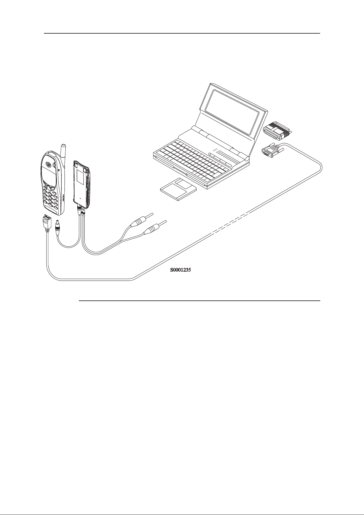
Equipment Setup for Tuning a Phone without Removing Covers
4.
1.
5.
2.
3.
Item: Service accessory: Product code:
1 Service Battery BBD–3 0775071
2 DC Cable SCB–3 0730114
3 Service MBUS Cable DAU–9P 0730109
4 Software protection key PKD–1 0750018
5 Service SW diskette 3.5” for WinTesla 0774046
6 Service SW diskette 3.5” for NSM–1 0774080
Original 10/98
Page 5
Page 6
NSM–1
PAMS
Tuning Instructions
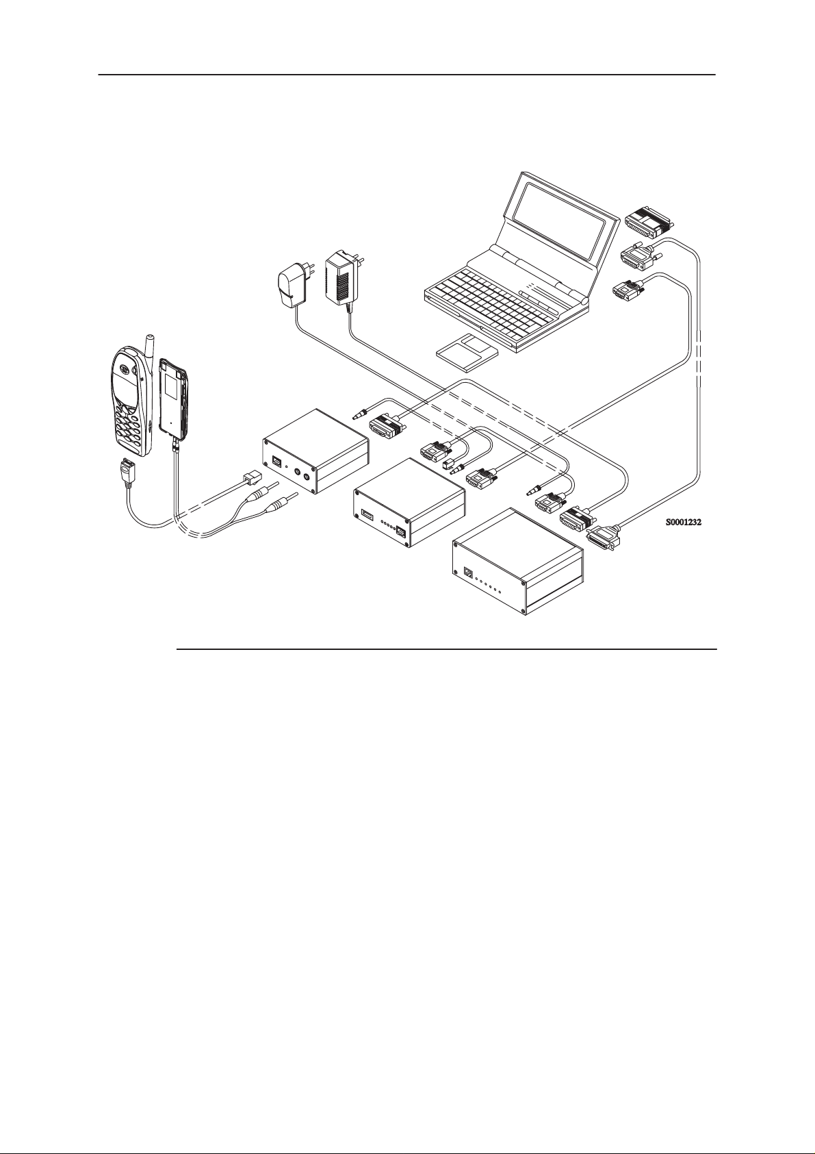
Flash Concept for NSM–1
12.
4.
5.
1.
6.
Technical Documentation
10.
13.
11.
9A.
7.
9B. 8.
2.
3.
Item: Service accessory: Product code:
1 Flash Loading Adapter FLA–5 0080178
2 Flash Security Box TDF–4 0770106
3 Prommer FPS–4S 0085095
4 Service Battery BBD–3 0775071
5 Service Cable SCH–5 0730098
6 DC Cable PCC–1B 0730053
7 D15 – D15 Cable AXS–5 0730091
(Included in FLA–5 sales pack)
8 Printer Cable (Included in FPS–4 sales pack) 0730029
9A D9 – D9 Cable AXS–4 0730090
(Included in FPS–4 sales pack)
9B D9 – D9 Cable AXS–4 0730090
10 Software protection key PKD–1 0750018
11 Service SW diskette 3.5” for NSM–1 0774080
Service SW diskette 3.5” for WinTesla 0774046
12 Travel Charger ACH–6E (Euro) 0270381
Travel Charger ACH–6U (USA/Japan) 0270382
Travel Charger ACH–6X (UK) 0270380
13 AC Charger ACL–3E 0680015
(Included in FPS–4 sales pack)
Page 6
Original 10/98
Page 7

PAMS
NSM–1
Technical Documentation
Tuning With Covers Off – Using Test–frame JBS–19
3.
4.
9.
6.
1.
Tuning Instructions
8.
7.
5.
2.
Item: Service accessory: Product code:
1 Module Jig JBS–19 * 0770098
SIM–Card Holder CAH–1 0770112
2 Service Audio Box JBA–4 ** 0770094
3 DC Cable PCS–1 0730012
4 External Antenna Cable XRC–1B 0730128
5 Service Cable SCH–5 ** 0730098
6 Service MBUS Cable DAU–9S ** 0730108
7 Audio Cable ADS–1 0730011
8 Software Protection Key PKD–1 0750018
9 Service SW diskette 3.5” for WinTesla 0774046
*) The nominal operating voltage for JBS–19 is 3.6 V.
**) SCH–5, JBA–4, and DAU–9S can be replaced with DAU–9P
Original 10/98
Service SW diskette 3.5” for NSM–1 0774080
The supply voltage for JBS–19 must never exceed 5.0 V
Page 7
Page 8

NSM–1
PAMS
Tuning Instructions
Tuning With Covers Off – using Light Jig JBT–1
3.
4.
1.
9.
7.
Technical Documentation
8.
6.
5.
2.
Item: Service accessory: Product code:
1 Light Module Jig JBT–1 * 0770109
2 Service Audio Box JBA–4 ** 0770094
3 DC Cable PCS–1 0730012
4 External Antenna Cable XRC–1B 0730128
5 Service Cable SCH–5 ** 0730098
6 Audio Cable ADS–1 0730011
7 Service MBUS Cable DAU–9S ** 0730108
8 Software Protection Key PKD–1 0750018
9 Service SW diskette 3.5” for WinTesla 0774046
Page 8
Service SW diskette 3.5” for NSM–1 0774080
*) The nominal operating voltage for JBT–1 is 3.6 V.
The supply voltage for JBT–1 must never exceed 5.0 V
**) SCH–5, JBA–4, and DAU–9S can be replaced with DAU–9P
Original 10/98
Page 9

PAMS
NSM–1
Technical Documentation
Warranty Transfer
Tuning Instructions
1.
Item: Service accessory: Product code:
1 Warranty Cable SCH–6 0730099
Original 10/98
Page 9
Page 10

NSM–1
PAMS
Tuning Instructions
Tuning Steps
1. RX Calibration (AGC + AFC)
Procedure
Follow the steps described in chapter ”Service Software Instructions” section ”RX calibration... command”.
Software reports the following:
AFC init value
AFC slope
PSW slope
AGC DAC values and the corresponding voltages for each gain step (0 57 dB)
Technical Documentation
Limits for the reported values
If everything went well the reported values should approximately be the
following:
Parameter Low limit High limit
AFC init value –80 80
AFC slope 130 230
PSW slope 250 350
AGC 0 dB 400 640
AGC 57 dB 100 300
Difference between the two neighbour
AGC steps
10 20
Troubleshooting
If the calibration does not succeed the software normally reports ”Unable
to read data from phone” or ”Failed to set high reference” or ”Failed to set
low reference”.
In this case check first the basic functionality of the receiver chain: RF
generator frequency set as in the calibration and level for example to the
high reference value.
Page 10
Then go to the RSSI reading menu (under RF controls). If the reading is
very low there is something broken in the receiver and must be found by
measuring voltages and signal levels at different places (information of
these can be found elsewhere in this manual).
If the RSSI reading seems to be within 5 - 10 dB the same as the RF input level check that the VCTCXO (G650) frequency is close enough the
Original 10/98
Page 11

PAMS
NSM–1
Technical Documentation
wanted frequency. This is most easiest done by measuring the UHF VCO
(G550) frequency because the absolute value of the deviation is biggest
there. In the GSM mid channel the UHF–VCO frequency should be
2040.0 MHz. If the deviation is bigger than about +/–20 kHz it is probable
that the VCTCXO is not operating correctly.
If both of these (RSSI reading and the frequency) seem to be correct and
calibration still fails the most probable reason is that there is a little lack of
gain somewhere or the AGC gain control slope in N600 is out of the limits.
This can be verified by changing the generator reference levels from the
demanded ones in the calibration procedure in 1 dB steps up and down. If
the calibration goes through with some reference levels the corrective action is most probably changing N500 or N600.
Tuning Instructions
Original 10/98
Page 11
Page 12
NSM–1
Á
Á
Á
Á
Á
Á
Á
Á
PAMS
Tuning Instructions
2. Alignment of Transmitter Power Levels
Equipment:
Pulsed power meter or spectrum analyzer and 10 dB attenuator.
Voltage source set to 3.6 V.
The following settings for the spectrum analyzer are recommended when
aligning the power levels: zero span, resolution and video bandwidths 1
MHz, input attenuation 40 dB, sweep time 1 ms, video triggering.
NOTE! If spectrum analyzer is used in power level alignment the
reading needs to be calibrated with a power meter after every power
up.
Procedure:
Follow the instructions given in chapter ”Service Software Instructions”
section ”TX power... command”.
For GSM the alignment channel is 60 (902 MHz) and for PCN 700
(1747.8 MHz). The side channels for GSM are 1 (890.2 MHz) and 124
(914.8 MHz) and for PCN 512 (1710.2 MHz) and 885 (1784.8 MHz).
Technical Documentation
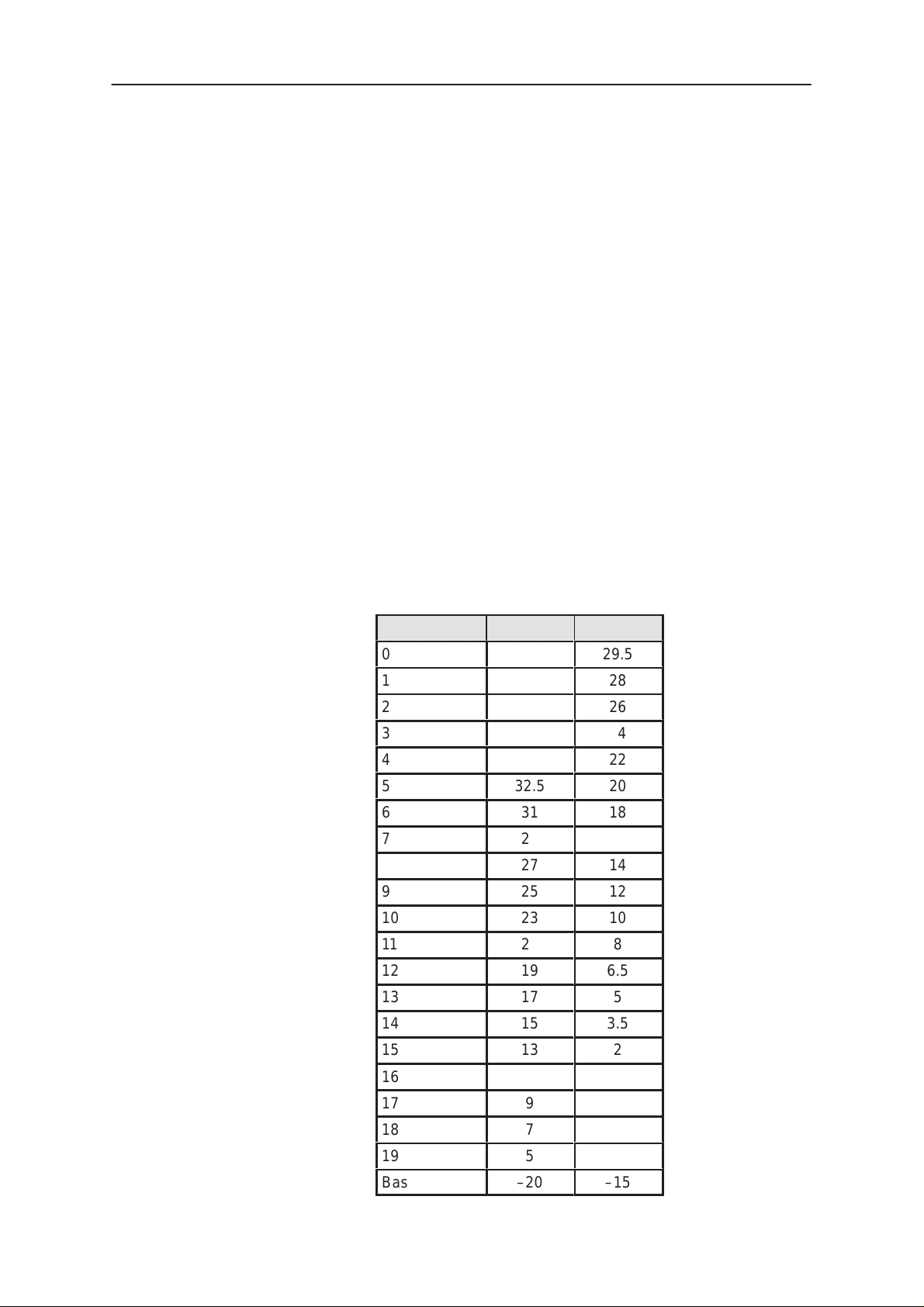
Targets in dBm:
Power level GSM PCN
0
1
ÁÁÁÁ
2
3
4
5
6
7
8
9
10
ÁÁÁÁ
11
12
13
14
15
ÁÁÁÁÁÁ
32.5
31
29
27
25
23
ÁÁÁ
21
19
17
15
13
29.5
28
26
24
22
20
18
16
14
12
10
ÁÁ
6.5
3.5
8
5
2
Page 12
16
17
18
19
ÁÁÁÁ
Base
11
9
7
5
ÁÁÁ
–20
ÁÁ
–15
Original 10/98
Page 13

PAMS
NSM–1
Technical Documentation
It is recommended that all the power levels are separately aligned although there is a possibility to align only three and calculate the rest. This
is due to the fact that the calculation is not accurate enough, especially
for PCN lowest power levels where the targets are NSM–1 specific.
NOTE! Base level must be adjusted manually because the calculation
most often fails.
Tuning Instructions
Original 10/98
Page 13
Page 14

NSM–1
PAMS
Tuning Instructions
3. I/Q Modulator Alignments
I/Q modulator alignments are performed in PCN band. If GSM band has
been selected and I/Q alignment is started, the service software asks to
change to PCN band. If the user wants to continue in GSM, the adjusted
values can only be saved to PC memory, not to phone’s EEPROM. After
changing to PCN band values from PC memory are available, and if the
modulator adjustment is good, also the values can be saved to phone’s
EEPROM. See chapter ”Service Software Instructions” and section ”TX
I/Q... command” for further information.
Procedure:
Connect the spectrum analyzer to the phone antenna connector. The recommended spectrum analyzer settings are: span 200 kHz, resolution BW
10 kHz, video BW 1 kHz, sweep 500 ms, input attenuation 30 dB.
– From
– Go to
(1747.8 MHz).
RF controls
TX I/Q tuning
menu make sure that TX data type is 1.
menu. The alignment channel for PCN is 700
Technical Documentation
– Select the ”TX I DC offset” option and adjust the level of the centre fre-
quency (CHF) to minimum.
– Select the ”TX Q DC offset” option and adjust the level of the CHF
again to minimum.
– After finding both minima change ”TX I DC offset” by step or two from
the current value to both directions to see, whether better minimum
can be found for CHF.
– Select the ”Amplitude Difference” option and adjust the level of the un-
wanted sideband CHF + 67.71 kHz to minimum.
– Select the ”Phase Difference” option and dajust the level of CHF +
67.71 kHz again to minimum.
– After all the minima have been found press ”Save” button to store the
values to phone EEPROM.
Targets:
The level of the centre frequency CHF should be at least 30 dB down to
the wanted sideband CHF - 67.71 kHz.
The level of the unwanted sideband CHF + 67.71 kHz should be at least
35 dB down to the wanted sideband CHF - 67.71 kHz.
Page 14
Alignment verification in GSM band:
– Go to
a SW reset for the phone. Which in turn is needed to get the aligned
I/Q values in use.
– Go to
– Go to
level 10, TX data type 1.
Product ––> Initialize ––> Normal mode
Product ––> Band ––> GSM
RF controls
menu and start transmission on channel 60, power
. This is needed to give
Original 10/98
Page 15

PAMS
NSM–1
Technical Documentation
– Check the levels of CHF and CHF + 67.71 kHz. Both the levels
should be at least 30 dB down to the wanted sideband CHF - 67.71
kHz. If both or either of the specifications is not met adjust the the re-
quired values (I and Q DC offsets for CHF and amplitude and phase
for CHF + 67.71kHz) to meet the specifications.
–67.71 kHz +67.71 kHz
D.C. offset
tunings:
Set this value
to minimum
CHF
> 30 dB
> 35 dB
Tuning Instructions
Amplitude &
phase difference:
Set this value
to minimum
– Store the results in PC memory.
– Go to
Product ––> Band ––> PCN
and then to
TX I/Q Tuning
to check
the alignment with the values which are in PC memory. If the specifications are not met in PCN the solution is to find compromise values
which are not optimum for either bands but still meet the specifications.
– If the PCN band alignment is good with the values from PC memory,
the TX I/Q tuning procedure can be stopped by pressing the ”Save”
button.
Original 10/98
Page 15
Page 16

NSM–1
PAMS
Tuning Instructions
4. Energy Management Calibration
See chapter ”Service Software Instructions” and section ”Tuning – Energy
Management Calibration... command” for further information.
Technical Documentation
Page 16
Original 10/98
 Loading...